EP2143357A2 - Längsprofil, Einsteckhülse sowie Tragkonstruktion aus einem Längsprofil und einer Einsteckhülse - Google Patents
Längsprofil, Einsteckhülse sowie Tragkonstruktion aus einem Längsprofil und einer Einsteckhülse Download PDFInfo
- Publication number
- EP2143357A2 EP2143357A2 EP09008855A EP09008855A EP2143357A2 EP 2143357 A2 EP2143357 A2 EP 2143357A2 EP 09008855 A EP09008855 A EP 09008855A EP 09008855 A EP09008855 A EP 09008855A EP 2143357 A2 EP2143357 A2 EP 2143357A2
- Authority
- EP
- European Patent Office
- Prior art keywords
- longitudinal profile
- longitudinal
- guide channels
- plug
- wall
- Prior art date
- Legal status (The legal status is an assumption and is not a legal conclusion. Google has not performed a legal analysis and makes no representation as to the accuracy of the status listed.)
- Granted
Links
Images


Classifications
-
- A—HUMAN NECESSITIES
- A47—FURNITURE; DOMESTIC ARTICLES OR APPLIANCES; COFFEE MILLS; SPICE MILLS; SUCTION CLEANERS IN GENERAL
- A47B—TABLES; DESKS; OFFICE FURNITURE; CABINETS; DRAWERS; GENERAL DETAILS OF FURNITURE
- A47B96/00—Details of cabinets, racks or shelf units not covered by a single one of groups A47B43/00 - A47B95/00; General details of furniture
- A47B96/14—Bars, uprights, struts, or like supports, for cabinets, brackets, or the like
- A47B96/1466—Bars, uprights, struts, or like supports, for cabinets, brackets, or the like with longitudinal grooves
-
- A—HUMAN NECESSITIES
- A47—FURNITURE; DOMESTIC ARTICLES OR APPLIANCES; COFFEE MILLS; SPICE MILLS; SUCTION CLEANERS IN GENERAL
- A47F—SPECIAL FURNITURE, FITTINGS, OR ACCESSORIES FOR SHOPS, STOREHOUSES, BARS, RESTAURANTS OR THE LIKE; PAYING COUNTERS
- A47F5/00—Show stands, hangers, or shelves characterised by their constructional features
- A47F5/08—Show stands, hangers, or shelves characterised by their constructional features secured to the wall, ceiling, or the like; Wall-bracket display devices
- A47F5/0807—Display panels, grids or rods used for suspending merchandise or cards supporting articles; Movable brackets therefor
- A47F5/0846—Display panels or rails with elongated channels; Sliders, brackets, shelves, or the like, slidably attached therein
Definitions
- the invention relates to a longitudinal profile according to the preamble of claim 1, a plug-in sleeve according to the preamble of claim 9 and a support structure of a longitudinal profile and a plug-in sleeve.
- German utility model 20 2004 017 332 is a substructure known as a supporting structure for a display wall.
- the substructure has support means in the form of hollow vertical supports, each provided with a space provided in the space recess for inserting a holder which is permanently installed in the support means.
- a plug-in receptacle is inserted, in which a support arm can be inserted lockable.
- the invention is based, in particular to simplify the construction of a display wall with a supporting substructure the task.
- the invention is based on a longitudinal profile for a display wall for attaching support elements for the presentation of goods.
- the longitudinal profile comprises fastening means for wall elements and attachment means for the arrangement of Einsteckhülsen, in which z. B. a support arm of a support member can be inserted locked.
- the longitudinal profile on a display side to which a display wall can be attached, has a longitudinal opening which extends continuously over at least a majority of the length of the longitudinal profile, and that on opposite side walls of the longitudinal profile in the longitudinal direction groove-like Guide channels are formed, the z. B. are accessible via the front of the longitudinal profile and in which the plug-in sleeves in particular the front side are inserted, wherein the plug-in sleeves are supported in the inserted state in the guide channels.
- the guide channels provide the support forces.
- the guide channels do not necessarily consist of continuous wall sections. It is conceivable that the guide channels have at least partially interrupted wall areas.
- the guide channels can be designed so that an insert sleeve can be pushed either frontally and / or from the front.
- the guide channel can have continuous wall regions which generate the groove shape.
- the insertion sleeve For inserting a plug-in sleeve into the guide channels, the insertion sleeve, viewed from the front, can use a plurality of cutouts in the guide channels with a corresponding subdivision on the insertion sleeve. It is also possible that the guide channels viewed from the display side and holding areas of a plug-in sleeve for the arrangement in the guide channels are at least partially comb-like coordinated with each other to perform insertion of the insertion of the display page.
- Plug-in sleeves should always be like a kind of sliding block at least partially in the lateral guide channels. This can be realized for insertion sleeves arbitrary positions along at least a portion of the longitudinal profile extension.
- a guide channel is formed by a first web, which forms an outer side of the longitudinal profile, and a second web arranged opposite the first web and arranged within the longitudinal profile.
- the guide channel thus has a clear width, which is less than the clear width of the longitudinal profile viewed overall in the direction of the display side.
- the width of the guide channel which is defined by the distance of lateral wall areas, be adjusted so that a necessary dimensioning of the insertion tube is material optimized. For given loads, it may be perfectly sufficient to work with a comparatively narrow guide channel, wherein corresponding holding areas on a plug-in sleeve are also formed thin-walled.
- the load capacity can be optimized for insertion sleeves.
- a guide channel tapers towards its open longitudinal side. This can be symmetrical or asymmetrical.
- the open longitudinal sides of the guide channels are opposite.
- bores for fastening screws are provided in the guide channel at predetermined intervals. This can be fixed in position after inserting a sleeve.
- the bores can be provided with an internal thread matched to an external thread of the fastening screws.
- the attachment sections can at the same time a Form side of the longitudinal, groove-like channels, which are formed for the cross connector.
- a longitudinal profile can be constructed symmetrically along the longitudinal axis.
- a plane of symmetry may be perpendicular to the display side or parallel thereto, for example through a wall opposite the display side.
- Another essential aspect of the invention relates to the insertion sleeve for the longitudinal profile just described, which has a plug-in portion having an insertion opening, e.g. a slot for a support arm comprises.
- the insertion sleeve has holding regions with respect to the insertion section, which can be inserted into longitudinally arranged guide channels of the longitudinal profile and provide the holding force for an inserted insertion sleeve in the longitudinal profile.
- the insertion section may have a longitudinal or a transverse slot for insertion of a support element. Other shapes, in particular round shapes, are also conceivable.
- the holding areas for the guide channels can be matched in their extension, in particular along the guide channels to a predetermined holding force. The larger the section in which the holding region of the insertion sleeve extends in the guide channel, the more resilient is the insertion sleeve. Further dimensioning possibility is the thickness of the holding region, which should be matched to the width of the groove-like guide channels, as well as the lateral extension into the guide channels inside, which is ultimately limited by the depth of the guide channels.
- the holding areas are formed on a flange, to which transversely, in particular perpendicular thereto, the insertion extends.
- the load capacity of the insert sleeve can be dimensioned.
- the flange element extends beyond a lateral boundary of the insertion section. This leads to improved leverage on an inserted insert sleeve.
- Another key aspect of the invention relates to a support structure for a display wall with a longitudinal profile and a plug-in sleeve.
- the support structure has a plurality of longitudinal profiles and insertion sleeves.
- holding regions on a plug-in sleeve in the cross-section perpendicular to its insertion direction in a longitudinal profile are modeled on the shape of the guide channels.
- the insertion regions have an undercut laterally transversely to an intended insertion direction.
- the guide channels are arranged in a groove, so that the openings of the guide channels are opposite and get outwardly a larger, clear width, so expand.
- the holding regions of the insertion sleeves are advantageously formed with a corresponding outer contour in cross section.
- the insertion sleeve If the insertion sleeve is seated at the predetermined position, it can then be inserted in the guide channel, e.g. be fixed by a screw or more screws, possibly also on existing holes in the grid and corresponding, already provided threads in the holding areas of the insertion.
- FIG. 1 shows a support structure 1 according to the invention with a rail 2 and a fixedly attached socket 3 with an insertion 23a.
- a display wall is added, which is shown by way of example in two different variants for illustrative purposes.
- the display wall is formed on one side of the socket 3 in two layers by plasterboard 4 and 5 and on the other side of the socket 3 by a wooden panel 6.
- the attachment of the display wall for example via fastening screws 8, 9, which pass through the front 7.
- the attachment of the display wall can also be done by gluing or other fastening.
- front 7 and an opposite rear wall 12 are side walls 13, 14 with inwardly directed guide channels 15, 16 in the form of groove-like depressions.
- the guide channels 15, 16 are aligned opposite each other with their open side to each other.
- the guide channels 15, 16 are bounded by a front web 15a and 16a and a spaced-apart in the direction of the rear wall 12 rear web 15b and 16b.
- the guide channels 15, 16 rejuvenate to their open Side, here for example by obliquely inclined to each other extending portions of the web portions 15 a, 15 b, 16 a, 16 b.
- the bushing 3 may be secured in position-accurate alignment with the rail 2 in one of a plurality of possible attachment points.
- the socket 3 can be mounted from the front side 7 on the rail 2 or correspondingly from a front end or from above, wherein the socket 3 can be positioned to the rail 2, that laterally projecting holding portions 21, 22 of the bushing 3 in groove-like guide channels 15 and 16 of the rail 2 can be used suitably or, if necessary, can be moved to a desired mounting position.
- the respective attached horizontal or vertical socket 3 or 32, 33, 34, 35 is an insertion 23a in transverse or longitudinal alignment to the longitudinal axis of the rail 2 and 30, 31 for insertion of a support member, not shown for the presentation of goods provided.
- the bushing 3 is screwed by fastening screws 10, 11 from the front via corresponding screw holes 17, 18 in web sections 15a, 15b, 16a, 16b of the guide channels 15, 16 and corresponding screw holes 21a and 22a in the socket, wherein corresponding matched to the screw thread threaded portions in
- the web portions 15b, 16b may be present.
- abutment sections 24, 25 are present, which adjoin the inside of the rear wall 12 to projectingly projecting webs 26, 27.
- FIG. 3 shows a vertical socket 3 in a single representation for the formation of an insertion opening 23 a shape of a Rectangular slot.
- the vertical socket 3 comprises a plug-in portion 19 having a receiving part 19a, on which a socket cover 23 can be plugged, and a flange portion 20, on which the holding portions 21, 22 are formed. Holes 21a and 22a are also provided in the region of the holding regions 21, 22, via which the bushing 3 can be screwed tightly to the profiled rail 2 with the attachment screws 10, the bores 21a and 22a being aligned with the screw holes 17, 18.
- a plurality of screw holes 17, 18 are present in the rail 2, wherein the distance matched by in the longitudinal extension of the rail 2 screw holes on the distance from superimposed holes on the holding portion 21 and 22 respectively is.
- the horizontal socket 3 extends in the attached state of the display wall by a matching recess in the display wall or the respective existing wall element 4.5 and 6.
- the socket cover 23 also includes a circumferential collar, which in the mounted state on a Outside of the display wall is applied.
- a bracket holder 28 may be bolted to the back of the wood panel 6 and releasably latched connected to a rearwardly projecting web 29 of the rail 2.
- FIG. 4 Illustrates in a front view of the rail 2 with the attached via the attachment screws 10 fixed horizontal bushing or FIG. 5 shows an attached vertical jack.
- the two profile rails 30, 31 are each constructed according to the rail 2, wherein at both rails 30, 31 at the same height in the longitudinal extension of the two rails 30, 31 for stabilizing or exact distance positioning to each other, the two rails 30, 31 via two spaced transverse connectors 36, 37 each end with the rails 30 and 31 connected.
- three adjustable feet 38 provided at the lower end. But there are also fewer or more adjustable feet per rail conceivable.
- the adjustable feet 38 are at the bottom of the rails 30, 31 can be screwed orHoschraubbar to possibly compensate for unevenness of a shelf for the rails 30, 31 can.
- FIG. 7 is shown on the rail 30 exemplified a bracket 39 is shown, which is screwed by screws 40 on a wall 41, wherein the bracket 39 is fixedly connected to the lateral regions of the rail 30.
- the cross connectors 36, 37 can as in FIG. 7 represented, be formed by hollow profiles, via plug adapter 42, the connection of the cross connector 37 with the rails 30, 31 takes place.
- the plug-in adapter 42 are provided with a plug-in section which can be inserted suitably on guide sides 43 formed on each side of the profile rails 30, 31.
- Corresponding grooves are also on the rail 2 outside of the side walls 13, 14 available.
Landscapes
- Finishing Walls (AREA)
- Supports Or Holders For Household Use (AREA)
- Display Racks (AREA)
Abstract
Description
- Die Erfindung betrifft ein Längsprofil nach dem Oberbegriff des Anspruchs 1, eine Einsteckhülse nach dem Oberbegriff des Anspruchs 9 sowie eine Tragkonstruktion aus einem Längsprofil und einer Einsteckhülse.
- Aus dem deutschen Gebrauchsmuster
20 2004 017 332 ist eine Unterkonstruktion als stützender Aufbau für eine Displaywand bekannt. - An der Unterkonstruktion sind eine Vielzahl systematisch angebrachter Tragvorrichtungen vorgesehen, die zum direkten oder indirekten Aufhängen von Artikeln oder zur Halterung einer Ablage bestimmt sind.
- Die Unterkonstruktion besitzt Stützmittel in Form von hohlen Vertikalstützen mit jeweils auf einer in den Raum gerichteten Fläche vorgesehenen Aussparung zum Einsetzen eines Halters, der im Stützmittel fest eingebaut ist.
- In die Hülse ist eine Steckaufnahme eingesetzt, in welche ein Tragarm sich arretierbar einstecken lässt.
- Der Erfindung liegt die Aufgabe zugrunde, insbesondere den Aufbau einer Displaywand mit einer stützenden Unterkonstruktion einfacher zu gestalten.
- Diese Aufgabe wird durch die Merkmale des Anspruchs 1, 9 sowie 12 gelöst.
- In den abhängigen Ansprüchen sind vorteilhafte und zweckmäßige Weiterbildungen der Erfindung angegeben.
- Die Erfindung geht von einem Längsprofil für eine Displaywand zum Anbringen von Tragelementen für die Präsentation von Waren aus. Das Längsprofil umfasst Befestigungsmittel für Wandelemente und Anbringmittel für die Anordnung von Einsteckhülsen, in welche z. B. ein Tragarm eines Tragelements arretierbar eingesteckt werden kann.
- Der Kern der Erfindung liegt darin, dass das Längsprofil auf einer Displayseite, an der eine Displaywand angebracht werden kann, eine längsverlaufende Öffnung aufweist, die sich zumindest über einen Großteil der Länge des Längsprofils durchgehend erstreckt, und dass an gegenüberliegenden Seitenwänden des Längsprofils in Längsrichtung nutenartige Führungskanäle ausgebildet sind, die z. B. über die Stirn des Längsprofils zugänglich sind und in welche die Einsteckhülsen insbesondere stirnseitig einschiebbar sind, wobei sich die Einsteckhülsen im eingeschobenen Zustand in den Führungskanälen abstützen.
- Damit wird auf einfache Weise eine Befestigungsmöglichkeit für Einsteckhülsen bereitgestellt, die vergleichsweise hoch belastbar ist.
- Die Führungskanäle stellen dabei die Abstützkräfte bereit. Die Führungskanäle müssen nicht zwangsläufig aus durchgehenden Wandabschnitten bestehen. Es ist denkbar, dass die Führungskanäle zumindest abschnittsweise unterbrochene Wandbereiche aufweisen.
- Die Führungskanäle können so ausgebildet sein, dass eine Einsteckhülse sich entweder stirnseitig und/oder von vorne einschieben lässt.
- Bei einer Einschiebbarkeit stirnseitig kann der Führungskanal durchgehende Wandbereiche aufweisen, die die Nutform erzeugen.
- Um ein Einsetzen von vorne zu ermöglichen, sollten systematische Aussparungen vorgesehen sein, die ein Einführen einer Einsteckhülse von vorne gewährleisten, wobei nach dem Einsteckvorgang die Einsteckhülse in einfacher Weise entlang des Längsprofils in durchgehende Wandbereiche verschiebbar ist, um so Belastungskräfte, die auf sie wirken, an das Längsprofil weitergeben zu können. In diesem Zusammenhang ist es auch denkbar, dass das Längsprofil an einer vorgegebenen Stelle eine Aussparung aufweist, um sozusagen ein Einfädeln einer Einsteckhülse von vorne und daran anschließend ein Einschieben in die Führungskanäle zu ermöglichen. Zum Einstecken einer Einsteckhülse in die Führungskanäle kann die Einsteckhülse auch von vorne betrachtet mehrere Aussparungen in den Führungskanälen nutzen mit einer entsprechenden Unterteilung an der Einsteckhülse. Es ist auch möglich, dass die Führungskanäle von der Displayseite aus betrachtet und Haltebereiche einer Einsteckhülse für die Anordnung in den Führungskanälen zumindest abschnittsweise kammartig aufeinander abgestimmt sind, um ein Einsetzen der Einsteckhülse von der Displayseite ausführen zu können.
- Einsteckhülsen sollten sich immer wie eine Art Nutenstein zumindest abschnittsweise in den seitlichen Führungskanälen verschieben lassen. Damit können für Einsteckhülsen beliebige Positionen entlang zumindest eines Abschnitts der Längsprofilerstreckung realisiert werden.
- In einer bevorzugten Ausgestaltung der Erfindung ist ein Führungskanal durch einen ersten Steg, der eine Außenseite des Längsprofils bildet, und einen dem ersten Steg gegenüberliegend und innerhalb des Längsprofils angeordneten zweiten Steg ausgebildet. Der Führungskanal weist damit eine lichte Weite auf, die geringer ist als die lichte Weite des Längsprofils insgesamt in Richtung Displayseite betrachtet. Damit kann die Breite des Führungskanals, die durch den Abstand von seitlichen Wandungsbereichen definiert wird, so eingestellt werden, dass eine notwendige Dimensionierung der Einsteckhülse materialoptimiert ist. Für vorgegebene Belastungen kann es vollkommen ausreichend sein, mit einem vergleichsweise schmalen Führungskanal zu arbeiten, wobei entsprechende Haltebereiche an einer Einsteckhülse ebenfalls dünnwandig ausgebildet sind.
- Auch über die Tiefe des nutartigen Führungskanals kann die Belastbarkeit für Einsteckhülsen optimiert werden.
- Um eine bestmögliche Fixierung einer Einsteckhülse in den Führungskanälen zu erreichen, wird im Weiteren vorgeschlagen, dass sich ein Führungskanal zu seiner offenen Längsseite hin verjüngt. Dies kann symmetrisch oder unsymmetrisch erfolgen. Durch eine Verjüngung wird erreicht, dass eine eingesteckte Einsteckhülse in einer Ebene, in welcher sich die Displayseite erstreckt und senkrecht zu der Einschubrichtung lagefixiert ist. Vorzugsweise liegen sich die offenen Längsseiten der Führungskanäle gegenüber.
- Zum einfachen Aufbau einer Unterkonstruktion einer Displaywand aus einer Mehrzahl von Längsprofilen wird überdies vorgeschlagen, dass an Wandabschnitten seitlich zur Displayseite Befestigungsorgane für Querverbinder zur Verbindung insbesondere zwei parallel angeordneter Längsprofile vorgesehen sind. Hierzu ist es vorteilhaft, wenn seitlich an den Längsprofilen in der Art, wie die Ausgestaltung der Führungskanäle, längsverlaufende, nutenartige Kanäle vorgesehen sind. In diese können dann Querverbinder, die sich von Längsprofil zu Längsprofil erstrecken, einfach eingeschoben werden.
- Zur Fixierung der Querverbinder kann es ausreichend sein, dass diese nach dem Einschieben in den nutenartigen Kanälen einfach mit einer Schraube lagefixiert werden.
- Um eine weitere Verbesserung der Fixierung von eingeschobenen Einsteckhülsen in das Längsprofil zu erreichen, wird darüber hinaus vorgeschlagen, dass auf der der Displayseite gegenüberliegenden Wand des Längsprofils auf der Innenseite zumindest ein Anschlagsteg vorgesehen ist. Im eingeschobenen Zustand kann sich daran eine Einsteckhülse zusätzlich zu Haltebereichen in den Führungskanälen abstützen.
- In einer besonders bevorzugten Ausgestaltung der Erfindung sind im Führungskanal in vorgegebenen Abständen Bohrungen für Befestigungsschrauben vorgesehen. Damit kann nach dem Einschieben einer Einsteckhülse diese lagefixiert werden. Die Bohrungen können mit einem auf ein Aussengwinde der Befestigungsschrauben abgestimmten Innengewinde versehen sein.
- Zur Befestigung einer Displaywand an der Displayseite des Längsprofils wird überdies vorgeschlagen, dass gesonderte Befestigungsabschnitte zum Montieren einer Displaywand, insbesondere über Schrauben vorgesehen sind.
- Die Befestigungsabschnitte können dabei gleichzeitig eine Seite der längsverlaufenden, nutartigen Kanäle bilden, die für die Querverbinder ausgebildet sind.
- Ein Längsprofil kann symmetrisch entlang der Längsachse aufgebaut sein. Eine Symmetrieebene kann senkrecht zur Displayseite liegen oder parallel dazu, beispielsweise durch eine der Displayseite gegenüberliegenden Wand. Durch diese Maßnahme ist prinzipiell eine Doppelbeblankung eines Längsprofils möglich, wobei sich auf eine Mittelwand bezogen, Führungskanalpaare beidseitig erstrecken.
- Ein weiterer wesentlicher Aspekt der Erfindung betrifft die Einsteckhülse für das soeben beschriebene Längsprofil, das einen Einsteckabschnitt besitzt, der eine Einstecköffnung, z.B. einen Schlitz für einen Tragarm umfasst.
- Die Einsteckhülse weist in Bezug auf den Einsteckabschnitt Haltebereiche auf, die sich in längs angeordnete Führungskanäle des Längsprofils einschieben lassen und die Haltekraft für eine eingeschobene Einsteckhülse in dem Längsprofil bereitstellen. Der Einsteckabschnitt kann einen Längs- oder einen Querschlitz zum Einstecken eines Tragelementes aufweisen. Andere Formen, insbesondere runde Formen, sind ebenfalls denkbar. Die Haltebereiche für die Führungskanäle können in ihrer Ausdehnung insbesondere entlang der Führungskanäle auf eine vorgegebene Haltekraft abgestimmt sein. Je größer der Abschnitt ist, in welchem sich der Haltebereich der Einsteckhülse im Führungskanal erstreckt, desto belastbarer ist die Einsteckhülse. Weitere Dimensionierungsmöglichkeit ist die Dicke des Haltebereichs, die auf die Breite der nutenartigen Führungskanäle abgestimmt sein sollte, sowie die laterale Erstreckung in die Führungskanäle hinein, die letztlich durch die Tiefe der Führungskanäle begrenzt wird.
- In einer besonders bevorzugten Ausgestaltung der Erfindung sind die Haltebereiche an einem Flanschelement ausgebildet, zu welchen quer, insbesondere senkrecht dazu, sich der Einsteckabschnitt erstreckt. Über die Größe des Flansches kann wiederum die Belastbarkeit der Einsteckhülse dimensioniert werden.
- Außerdem bevorzugt ist es, wenn sich das Flanschelement in einer Einsteckrichtung des Einsteckabschnitts betrachtet über eine seitliche Begrenzung des Einsteckabschnitts hinaus erstreckt. Das führt zu verbesserten Hebelverhältnissen an einer eingeschobenen Einsteckhülse.
- Ein weiterer Kernaspekt der Erfindung bezieht sich auf eine Tragkonstruktion für eine Displaywand mit einem Längsprofil und einer Einsteckhülse. Vorzugsweise weist die Tragkonstruktion eine Vielzahl von Längsprofilen und Einsteckhülsen auf.
- In einer besonders bevorzugten Ausgestaltung der Erfindung sind Haltebereiche an einer Einsteckhülse im Querschnitt senkrecht zu ihrer Einschubrichtung in ein Längsprofil betrachtet der Form der Führungskanäle nachgebildet. Damit kann ein satter Sitz der Haltebereiche und damit der Einsteckhülse in den Führungskanälen für die Einsteckhülse gewährleistet werden. Um eine laterale Fixierung der Einsteckhülsen zu ermöglichen, wird überdies vorgeschlagen, dass die Einsteckbereiche seitlich quer zu einer vorgesehenen Einschubrichtung betrachtet eine Hinterschneidung aufweisen. Zum Beispiel sind die Führungskanäle nutenartig so angeordnet, dass die Öffnungen der Führungskanäle sich gegenüber liegen und nach außen hin eine größere, lichte Weite bekommen, sich also aufweiten. Die Haltebereiche der Einsteckhülsen sind vorteilhafterweise mit einer entsprechenden Außenkontur im Querschnitt ausgebildet. Damit ist die Position von senkrecht zu einer Verschieberichtung in den Führungskanälen eingesteckten Einsteckhülsen lateral festgelegt. Lediglich eine Verschiebung entlang der nutenartigen Führungskanäle ist noch möglich.
- Sitzt die Einsteckhülse an der vorbestimmten Position, kann diese dann im Führungskanal z.B. durch eine Schraube oder mehrere Schrauben fixiert werden, gegebenenfalls auch an im Raster vorhandenen Bohrungen und entsprechenden, bereits vorgesehenen Gewinden in den Haltebereichen der Einsteckhülse.
- Anhand der in den Figuren gezeigten Ausführungsbeispiele sind weiterer Merkmale und Vorteile der Erfindung näher erläutert. Im Einzelnen zeigt:
- Figur 1
- einen Ausschnitt einer erfindungsgemäßen Tragkonstruktion mit einer Displaywand im Schnitt,
- Figur 2
- stirnseitig eine Profilschiene der in
Figur 1 gezeigten Tragkonstruktion, - Figur 3
- eine Vertikal-Buchse der erfindungsgemäßen Tragkonstruktion von oben,
- Figur 4 und 5
- jeweils einen Ausschnitt einer Tragkonstruktion mit einer Horizontal-Buchse bzw. einer Vertikal-Buchse an jeder Profilschiene,
- Figur 6
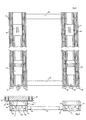
- einen unteren Endabschnitt einer Tragkonstruktion in einer Vorderansicht mit zwei über Verbindungselemente verbundenen Profilschienen und
- Figur 7
- die Anordnung gemäß
Figur 6 in einem Querschnitt im Bereich einer Wandanbindung einer der Profilschienen. -
Figur 1 zeigt eine erfindungsgemäße Tragkonstruktion 1 mit einer Profilschiene 2 und einer daran fest angebrachten Buchse 3 mit einer Einstecköffnung 23a. Über die Tragkonstruktion 1 ist eine Displaywand aufgenommen, die zur Veranschaulichung beispielhaft in zwei unterschiedlichen Varianten gezeigt ist. Die Displaywand ist auf der einen Seite der Buchse 3 zweilagig durch Gipskartonplatten 4 und 5 und auf der anderen Seite der Buchse 3 durch eine Holzpaneele 6 gebildet. - An ebenen Wandungsabschnitten einer Vorderseite 7 der Profilschiene 2, seitlich neben einer Öffnung 7a in der Vorderseite 7, erfolgt die Anbringung der Displaywand beispielsweise über Befestigungsschrauben 8, 9, welche die Vorderseite 7 durchgreifen. Gegebenenfalls kann die Anbringung der Displaywand auch durch Kleben oder eine andere Befestigungsart erfolgen. Mit der Profilschiene 2 können auch andere z.B. Trockenbauprofile entsprechend verbunden werden.
- Zwischen der Vorderseite 7 und einer gegenüberliegenden Rückwand 12 sind Seitenwände 13, 14 mit nach innen gerichteten Führungskanälen 15, 16 in Form von nutartigen Vertiefungen vorhanden. Die Führungskanäle 15, 16 sind gegenüberliegend mit ihrer offenen Seite zueinander ausgerichtet.
- Die Führungskanäle 15, 16 werden durch einen vorderen Steg 15a bzw. 16a und einen dazu beabstandeten in Richtung der Rückwand 12 liegenden hinteren Steg 15b bzw. 16b begrenzt. Die Führungskanäle 15, 16 verjüngen sich zu ihrer offenen Seite hin, hier beispielsweise durch schräg zueinander geneigt verlaufende Abschnitte der Stegabschnitte 15a, 15b, 16a, 16b.
- An der insbesondere aus einem Metall z.B. einem Aluminiumwerkstoff gebildeten Profilschiene 2 kann die Buchse 3 in positionsgenauer Ausrichtung zur Profilschiene 2 in einer von einer Mehrzahl möglichen Anbringstellen befestigt sein. Hierzu kann die Buchse 3 von der Vorderseite 7 an der Profilschiene 2 angebracht werden oder entsprechend von einem stirnseitigen Ende bzw. von oben, wobei die Buchse 3 so zur Profilschiene 2 positionierbar ist, dass seitlich abstehende Haltebereiche 21, 22 der Buchse 3 in nutartige Führungskanälen 15 und 16 der Profilschiene 2 passend einsetzbar bzw. ggf. darin bis zu einer gewünschten Anbringposition verschoben werden können. Mit der jeweils angebrachten Horizontal- bzw. Vertikal-Buchse 3 bzw. 32, 33, 34, 35 wird eine Einstecköffnung 23a in Quer- oder Längsausrichtung zur Längsachse der Profilschiene 2 bzw. 30, 31 zum Einstecken eines nicht gezeigten Tragelements zur Präsentation von Waren bereitgestellt.
- Die Buchse 3 wird über Befestigungsschrauben 10, 11 von vorne über entsprechende Schraublöcher 17, 18 in Stegabschnitten 15a, 15b, 16a, 16b der Führungskanäle 15, 16 und entsprechende Schraublöcher 21a und 22a in der Buchse angeschraubt, wobei entsprechende auf die Schraubengewinde abgestimmte Gewindeabschnitte in z.B. den Stegabschnitten 15b, 16b vorhanden sein können. Für eine Abstützung der angebrachten Horizontal-Buchse 3 gemäß
Figur 1 sind Anlageabschnitte 24, 25 vorhanden, welche an nach vorne abstehenden Stegen 26, 27 innen an der Rückwand 12 abstützend angrenzen. -
Figur 3 zeigt eine Vertikal-Buchse 3 in Einzeldarstellung für die Ausbildung einer Einstecköffnung 23a Form eines Rechteckschlitzes. - Die Vertikal-Buchse 3 umfasst einen Einsteckabschnitt 19 mit einem Aufnahmeteil 19a, auf das eine Buchsenabdeckung 23 aufsteckbar ist, und einen Flanschabschnitt 20, an welchem die Haltebereiche 21, 22 ausgebildet sind. Im Bereich der Haltebereiche 21, 22 sind außerdem Bohrungen 21a bzw. 22a vorgesehen, über welche mit den Anbringschrauben 10 die Buchse 3 fest mit der Profilschiene 2 verschraubbar ist, wobei die Bohrungen 21a bzw. 22a mit den Schraublöchern 17, 18 fluchten. Für eine flexible Positionierung der Buchse 3 entlang der Profilschiene 2 sind in der Profilschiene 2 eine Vielzahl von Schraublöchern 17, 18 vorhanden, wobei der Abstand von in Längserstreckung der Profilschiene 2 fluchtenden Schraublöchern auf den Abstand von übereinanderliegenden Bohrungen an dem Haltebereich 21 bzw. 22 abgestimmt ist.
- Wie aus
Figur 1 außerdem ersichtlich ist, reicht die Horizontal-Buchse 3 im angebrachten Zustand der Displaywand durch eine passende Ausnehmung in der Displaywand bzw. dem jeweils vorhandenen Wandelement 4,5 bzw. 6. Die Buchsenabdeckung 23 umfasst zudem einen umlaufenden Kragen, welcher im aufgesteckten Zustand an einer Außenseite der Displaywand anliegt. - Zur rückseitigen Fixierung beispielsweise der Holzpaneele 6 an der Profilschiene 2 kann ein Bügelhalter 28 rückwärtig an der Holzpaneele 6 verschraubt sein und lösbar verrastet verbunden mit einem nach hinten abstehenden Steg 29 der Profilschiene 2.
-
Figur 4 veranschaulicht in einer Vorderansicht die Profilschiene 2 mit der daran über die Anbringschrauben 10 fest angebrachten Horizontalbuchse bzw.Figur 5 zeigt eine angebrachte Vertikal-Buchse. -
Figur 6 und Figur 7 zeigen eine Anordnung mit zwei in einem definierten Abstand zueinander parallel und senkrecht verlaufenden Profilschienen 30, 31. Die beiden Profilschienen 30, 31 sind jeweils gemäß der Profilschiene 2 aufgebaut, wobei bei beiden Profilschienen 30, 31 auf gleicher Höhe in Längserstreckung der beiden Profilschienen 30, 31 jeweils eine Vertikal-Buchse 32, 33 angebracht ist und versetzt jeweils eine Horizontal-Buchse 34, 35. Zur Stabilisierung bzw. exakten Abstandspositionierung zueinander sind die beiden Profilschienen 30, 31 über zwei beabstandete Querverbinder 36, 37 jeweils endseitig mit den Profilschienen 30 und 31 verbunden. Für eine exakte Nivellierung bzw. Ausrichtung und Abstützung der Profilschienen 30, 31 sind daran hier beispielsweise jeweils drei Stellfüße 38 am unteren Ende vorgesehen. Es sind aber auch weniger oder mehr Stellfüße pro Profilschiene denkbar. Die Stellfüße 38 sind unten in die Profilschienen 30, 31 einschraubbar bzw. herausschraubbar, um ggf. Unebenheiten einer Abstellfläche für die Profilschienen 30, 31 ausgleichen zu können. InFigur 7 ist an der Profilschiene 30 beispielhaft dargestellt ein Haltewinkel 39 gezeigt, welcher über Schrauben 40 an einer Wand 41 anschraubbar ist, wobei der Haltewinkel 39 fest mit den seitlichen Bereichen der Profilschiene 30 verbunden ist. - Die Querverbinder 36, 37 können wie in
Figur 7 dargestellt, durch Hohlprofile gebildet sein, wobei über Steckadapter 42 die Verbindung der Querverbinder 37 mit den Profilschienen 30, 31 erfolgt. Hierzu sind die Steckadapter 42 mit einem Einsteckabschnitt versehen, welcher passend auf jeweils an Seiten der Profilschienen 30, 31 ausgebildeten Führungsnuten 43 einbringbar ist. - Entsprechende Nuten sind auch an der Profilschiene 2 außen an den Seitenwänden 13, 14 vorhanden.
-
- 1
- Tragkonstruktion
- 2
- Profilschiene
- 3
- Buchse
- 4
- Gipskartonplatte
- 5
- Gipskartonplatte
- 6
- Holzpaneele
- 7
- Vorderseite
- 7a
- Öffnung
- 8
- Befestigungsschraube
- 9
- Befestigungsschraube
- 10
- Anbringschraube
- 11
- Anbringschraube
- 12
- Rückwand
- 13
- Seitenwand
- 14
- Seitenwand
- 15
- Führungskanal
- 15a
- Stegabschnitt
- 15b
- Stegabschnitt
- 16
- Führungskanal
- 16a
- Stegabschnitt
- 16b
- Stegabschnitt
- 17
- Schraubloch
- 18
- Schraubloch
- 19
- Einsteckabschnitt
- 19a
- Aufnahmeteil
- 20
- Flanschabschnitt
- 21
- Haltebereich
- 21a
- Bohrung
- 22
- Haltebereich
- 22a
- Bohrung
- 23
- Buchsenabdeckung
- 23a
- Einstecköffnung
- 24
- Anlageabschnitt
- 25
- Anlageabschnitt
- 26
- Steg
- 27
- Steg
- 28
- Bügelhalter
- 29
- Steg
- 30
- Profilschiene
- 31
- Profilschiene
- 32
- Buchse
- 33
- Buchse
- 34
- Buchse
- 35
- Buchse
- 36
- Querverbinder
- 37
- Querverbinder
- 38
- Stellfuß
- 39
- Haltewinkel
- 40
- Schraube
- 41
- Wand
- 42
- Steckadapter
- 43
- Führungsnut
Claims (14)
- Längsprofil für eine Displaywand zum Anbringen von Tragelementen für die Präsentation von Waren mit Befestigungsmitteln für Wandelemente und mit Anbringmitteln für die Anordnung von Einsteckhülsen (3, 32, 33, 34, 35), in welche ein Tragelement arretierbar eingesteckt werden kann, dadurch gekennzeichnet, dass das Längsprofil (2, 30, 31) auf einer Displayseite, an der eine Displaywand (4, 5, 6) angebracht werden kann, eine längsverlaufende Öffnung (7a) aufweist, die sich zumindest über einen Großteil der Länge des Längsprofils (2, 30, 31) durchgehend erstreckt, und dass an gegenüberliegenden Seitenwänden (13, 14) des Längsprofils (2, 30, 31) in Längsrichtung nutenartige Führungskanäle (15, 16) ausgebildet sind, in welche die Einsteckhülsen (3, 32, 33, 34, 35) einschiebbar sind, wobei sich die Einsteckhülsen (3, 32, 33, 34, 35) im eingeschobenen Zustand in den Führungskanälen (15, 16) abstützen.
- Längsprofil nach Anspruch 1, dadurch gekennzeichnet, dass ein Führungskanal (15, 16) durch einen ersten Steg (15a, 16a), der eine Außenseite des Längsprofils (2, 30, 31) bildet, und einen dem ersten Steg (15a, 16a) gegenüberliegend und innerhalb des Längsprofils (2, 30, 31) angeordneten zweiten Steg (15b, 16b) ausgebildet ist.
- Längsprofil nach einem der vorhergehenden Ansprüche, dadurch gekennzeichnet, dass sich ein Führungskanal (15, 16) zu einer offenen Längsseite hin verjüngt.
- Längsprofil nach einem der vorhergehenden Ansprüche, dadurch gekennzeichnet, dass an Wandabschnitten seitlich zur Displayseite Befestigungsorgane (42) für Querverbinder (36, 37) zur Verbindung mehrerer, insbesondere zwei parallel angeordneter Längsprofile (30, 31) vorgesehen sind.
- Längsprofil nach einem der vorhergehenden Ansprüche, dadurch gekennzeichnet, dass auf der der Displayseite gegenüberliegenden Wand (12) des Längsprofils (2, 30, 31) auf der Innenseite zumindest ein Anschlagsteg (26, 27) vorgesehen ist.
- Längsprofil nach einem der vorhergehenden Ansprüche, dadurch gekennzeichnet, dass ein Führungskanal (15, 16) in vorgegebenen Abständen Bohrungen (17, 18) für Befestigungsschrauben (10, 11) aufweist.
- Längsprofil nach einem der vorhergehenden Ansprüche, dadurch gekennzeichnet, dass auf der Displayseite des Längsprofils (2, 30, 31) Befestigungsabschnitte für eine Displaywand (4, 5, 6) vorgesehen sind.
- Längsprofil nach einem der vorhergehenden Ansprüche, dadurch gekennzeichnet, dass das Längsprofil (2, 30, 31) symmetrisch entlang der Längsachse aufgebaut ist.
- Einsteckhülse (3, 32, 33, 34, 35) für ein Längsprofil (2, 30, 31) nach einem der vorhergehenden Ansprüche mit einem Einsteckabschnitt (19), der eine Einstecköffnung (23a) für ein Tragelement besitzt, dadurch gekennzeichnet, dass in Bezug auf den Einsteckabschnitt (19) quer angeordnete Haltebereiche (21, 22) vorgesehen sind, die sich in längsangeordnete, nutenartige Führungskanäle (15, 16) eines Längsprofils (2, 30, 31) einschieben lassen und die Haltekräfte für eine in ein Längsprofil (2, 30, 31) eingeschobene Einsteckhülse (3, 32, 33, 34, 35) bereitstellen.
- Einsteckhülse nach Anspruch 9, dadurch gekennzeichnet, dass die Haltebereiche (21, 22) an einem Flanschelement (20) ausgebildet sind, zu welchem quer, insbesondere senkrecht dazu sich der Einsteckabschnitt (19) erstreckt.
- Einsteckhülse nach einem der Ansprüche 9 oder 10, dadurch gekennzeichnet, dass sich das Flanschelement (20) in einer Einsteckrichtung des Einsteckabschnitts (19) betrachtet über eine seitliche Begrenzung des Einsteckabschnitts (19) hinaus erstreckt.
- Tragkonstruktion für eine Displaywand (4, 5, 6) mit einem Längsprofil (2, 30, 31) nach einem der Ansprüche 1 bis 8 und einer Einsteckhülse (3, 32, 33, 34, 35) nach einem der Ansprüche 9 bis 11.
- Tragkonstruktion nach Anspruch 12, dadurch gekennzeichnet, dass die Haltebereiche (21, 22) im Querschnitt senkrecht zu ihrer vorgesehenen Einschubrichtung in ein Längsprofil (2, 30, 31) betrachtet der Form der nutenartigen Führungskanäle (15, 16) entsprechen.
- Tragkonstruktion nach einem der Ansprüche 12 oder 13, dadurch gekennzeichnet, dass die Haltebereiche (21, 22) seitlich quer zu einer vorgesehenen Einschubrichtung betrachtet eine Hinterschneidung aufweisen.
Applications Claiming Priority (1)
| Application Number | Priority Date | Filing Date | Title |
|---|---|---|---|
| DE200810032433 DE102008032433A1 (de) | 2008-07-10 | 2008-07-10 | Längsprofil, Einsteckhülse sowie Tragkonstruktion aus einem Längsprofil und einer Einsteckhülse |
Publications (3)
| Publication Number | Publication Date |
|---|---|
| EP2143357A2 true EP2143357A2 (de) | 2010-01-13 |
| EP2143357A3 EP2143357A3 (de) | 2011-09-28 |
| EP2143357B1 EP2143357B1 (de) | 2016-10-05 |
Family
ID=41226155
Family Applications (1)
| Application Number | Title | Priority Date | Filing Date |
|---|---|---|---|
| EP09008855.0A Not-in-force EP2143357B1 (de) | 2008-07-10 | 2009-07-07 | Längsprofil, Einsteckhülse sowie Tragkonstruktion aus einem Längsprofil und einer Einsteckhülse |
Country Status (2)
| Country | Link |
|---|---|
| EP (1) | EP2143357B1 (de) |
| DE (1) | DE102008032433A1 (de) |
Citations (1)
| Publication number | Priority date | Publication date | Assignee | Title |
|---|---|---|---|---|
| DE202004017332U1 (de) | 2004-11-09 | 2005-01-27 | Visplay International Ag | Unterkonstruktion als stützender Aufbau für eine Displaywand |
Family Cites Families (6)
| Publication number | Priority date | Publication date | Assignee | Title |
|---|---|---|---|---|
| US3039727A (en) * | 1961-01-30 | 1962-06-19 | Miller Herman Inc | Bracket |
| US3562970A (en) * | 1969-05-21 | 1971-02-16 | Paul Schwartz | Metal studding and adjustable shelf carrier |
| US3714748A (en) * | 1970-01-02 | 1973-02-06 | Angeles Metal Trim Co | Support structure for shelving |
| CH678687A5 (de) * | 1989-06-23 | 1991-10-31 | Fehlbaum & Co | |
| DE20109009U1 (de) * | 2001-05-30 | 2001-08-30 | Brose GmbH, 69190 Walldorf | Befestigungsvorrichtung zum Verbinden von Flächenelementen mit einer Tragkonstruktion |
| DE102005004654B4 (de) * | 2005-02-02 | 2018-12-13 | Hans-Georg Kraiss | Flexibles Präsentationssystem und Profilschiene hierfür |
-
2008
- 2008-07-10 DE DE200810032433 patent/DE102008032433A1/de not_active Withdrawn
-
2009
- 2009-07-07 EP EP09008855.0A patent/EP2143357B1/de not_active Not-in-force
Patent Citations (1)
| Publication number | Priority date | Publication date | Assignee | Title |
|---|---|---|---|---|
| DE202004017332U1 (de) | 2004-11-09 | 2005-01-27 | Visplay International Ag | Unterkonstruktion als stützender Aufbau für eine Displaywand |
Also Published As
| Publication number | Publication date |
|---|---|
| EP2143357B1 (de) | 2016-10-05 |
| EP2143357A3 (de) | 2011-09-28 |
| DE102008032433A1 (de) | 2010-01-14 |
Similar Documents
| Publication | Publication Date | Title |
|---|---|---|
| DE102008006439B4 (de) | Bausatz aus Konstruktionsprofil, Profilverbinder und Tragarmen | |
| EP3862510B1 (de) | Ausgleichsträger | |
| EP0244582A2 (de) | Bausatz für Möbelelemente | |
| DE69402525T2 (de) | Gerüst mit variabler grösse für elektrische und/oder elektronische anlage | |
| DE202005006528U1 (de) | Befestigungsprofil | |
| DE202006005039U1 (de) | Profil für eine Leuchtwand und Leuchtwandprofilsystem | |
| EP0004374A1 (de) | Vorrichtung zum Verbinden von zwei Profilstäben | |
| EP2348920B1 (de) | Baukasten | |
| EP3643846A1 (de) | Schiene | |
| EP2143357B1 (de) | Längsprofil, Einsteckhülse sowie Tragkonstruktion aus einem Längsprofil und einer Einsteckhülse | |
| EP3461963B1 (de) | Trägersystem und system von verbindungselementen zur verbindung von trägern | |
| EP1936055A2 (de) | Profil für Profilsysteme | |
| EP3798379B1 (de) | Profilsystem und stellsystem sowie verfahren zur herstellung eines profilsystems und verwendung des profilsystems und/oder des stellsystems | |
| DE29509555U1 (de) | Schaltschrank mit Montageplatte als Einzel- oder Anreihschrank | |
| EP1193822A2 (de) | Sammelschienenträger | |
| DE29924191U1 (de) | Regal | |
| DE10224588B4 (de) | Schranksystem mit mindestens einem Einschubelement | |
| DE102009011707A1 (de) | Modulares Regalsystem | |
| EP4114150A1 (de) | Erweiterungsbausatz | |
| DE102005026619A1 (de) | Verbindungselement für Profilstangen | |
| EP3130716B1 (de) | Wandbauplatte und wandbausystem für den messebau | |
| EP1001112B1 (de) | Gerüst für eine Schalung zur Herstellung einer Voute | |
| DE9107593U1 (de) | Zusammengesetztes Türschild | |
| DE4014083A1 (de) | Wange fuer bueromoebel | |
| EP2083127A2 (de) | Anschlusskopf und System zum Erstellen von Aufbauten |
Legal Events
| Date | Code | Title | Description |
|---|---|---|---|
| PUAI | Public reference made under article 153(3) epc to a published international application that has entered the european phase |
Free format text: ORIGINAL CODE: 0009012 |
|
| AK | Designated contracting states |
Kind code of ref document: A2 Designated state(s): AT BE BG CH CY CZ DE DK EE ES FI FR GB GR HR HU IE IS IT LI LT LU LV MC MK MT NL NO PL PT RO SE SI SK SM TR |
|
| PUAL | Search report despatched |
Free format text: ORIGINAL CODE: 0009013 |
|
| AK | Designated contracting states |
Kind code of ref document: A3 Designated state(s): AT BE BG CH CY CZ DE DK EE ES FI FR GB GR HR HU IE IS IT LI LT LU LV MC MK MT NL NO PL PT RO SE SI SK SM TR |
|
| AX | Request for extension of the european patent |
Extension state: AL BA RS |
|
| RIC1 | Information provided on ipc code assigned before grant |
Ipc: A47F 5/08 20060101AFI20110824BHEP Ipc: A47B 96/14 20060101ALI20110824BHEP |
|
| 17P | Request for examination filed |
Effective date: 20120327 |
|
| RAP1 | Party data changed (applicant data changed or rights of an application transferred) |
Owner name: SHOP SYSTEMS KNOBLAUCH GMBH |
|
| RAP1 | Party data changed (applicant data changed or rights of an application transferred) |
Owner name: SHOP SYSTEMS GMBH |
|
| 17Q | First examination report despatched |
Effective date: 20151104 |
|
| GRAP | Despatch of communication of intention to grant a patent |
Free format text: ORIGINAL CODE: EPIDOSNIGR1 |
|
| INTG | Intention to grant announced |
Effective date: 20160429 |
|
| GRAS | Grant fee paid |
Free format text: ORIGINAL CODE: EPIDOSNIGR3 |
|
| GRAA | (expected) grant |
Free format text: ORIGINAL CODE: 0009210 |
|
| AK | Designated contracting states |
Kind code of ref document: B1 Designated state(s): AT BE BG CH CY CZ DE DK EE ES FI FR GB GR HR HU IE IS IT LI LT LU LV MC MK MT NL NO PL PT RO SE SI SK SM TR |
|
| REG | Reference to a national code |
Ref country code: GB Ref legal event code: FG4D Free format text: NOT ENGLISH |
|
| REG | Reference to a national code |
Ref country code: CH Ref legal event code: EP |
|
| REG | Reference to a national code |
Ref country code: AT Ref legal event code: REF Ref document number: 833834 Country of ref document: AT Kind code of ref document: T Effective date: 20161015 |
|
| REG | Reference to a national code |
Ref country code: IE Ref legal event code: FG4D Free format text: LANGUAGE OF EP DOCUMENT: GERMAN |
|
| REG | Reference to a national code |
Ref country code: DE Ref legal event code: R096 Ref document number: 502009013159 Country of ref document: DE |
|
| REG | Reference to a national code |
Ref country code: NL Ref legal event code: MP Effective date: 20161005 |
|
| REG | Reference to a national code |
Ref country code: LT Ref legal event code: MG4D |
|
| PG25 | Lapsed in a contracting state [announced via postgrant information from national office to epo] |
Ref country code: LV Free format text: LAPSE BECAUSE OF FAILURE TO SUBMIT A TRANSLATION OF THE DESCRIPTION OR TO PAY THE FEE WITHIN THE PRESCRIBED TIME-LIMIT Effective date: 20161005 |
|
| PG25 | Lapsed in a contracting state [announced via postgrant information from national office to epo] |
Ref country code: GR Free format text: LAPSE BECAUSE OF FAILURE TO SUBMIT A TRANSLATION OF THE DESCRIPTION OR TO PAY THE FEE WITHIN THE PRESCRIBED TIME-LIMIT Effective date: 20170106 Ref country code: SE Free format text: LAPSE BECAUSE OF FAILURE TO SUBMIT A TRANSLATION OF THE DESCRIPTION OR TO PAY THE FEE WITHIN THE PRESCRIBED TIME-LIMIT Effective date: 20161005 Ref country code: LT Free format text: LAPSE BECAUSE OF FAILURE TO SUBMIT A TRANSLATION OF THE DESCRIPTION OR TO PAY THE FEE WITHIN THE PRESCRIBED TIME-LIMIT Effective date: 20161005 Ref country code: NO Free format text: LAPSE BECAUSE OF FAILURE TO SUBMIT A TRANSLATION OF THE DESCRIPTION OR TO PAY THE FEE WITHIN THE PRESCRIBED TIME-LIMIT Effective date: 20170105 |
|
| PG25 | Lapsed in a contracting state [announced via postgrant information from national office to epo] |
Ref country code: IS Free format text: LAPSE BECAUSE OF FAILURE TO SUBMIT A TRANSLATION OF THE DESCRIPTION OR TO PAY THE FEE WITHIN THE PRESCRIBED TIME-LIMIT Effective date: 20170205 Ref country code: PL Free format text: LAPSE BECAUSE OF FAILURE TO SUBMIT A TRANSLATION OF THE DESCRIPTION OR TO PAY THE FEE WITHIN THE PRESCRIBED TIME-LIMIT Effective date: 20161005 Ref country code: FI Free format text: LAPSE BECAUSE OF FAILURE TO SUBMIT A TRANSLATION OF THE DESCRIPTION OR TO PAY THE FEE WITHIN THE PRESCRIBED TIME-LIMIT Effective date: 20161005 Ref country code: ES Free format text: LAPSE BECAUSE OF FAILURE TO SUBMIT A TRANSLATION OF THE DESCRIPTION OR TO PAY THE FEE WITHIN THE PRESCRIBED TIME-LIMIT Effective date: 20161005 Ref country code: PT Free format text: LAPSE BECAUSE OF FAILURE TO SUBMIT A TRANSLATION OF THE DESCRIPTION OR TO PAY THE FEE WITHIN THE PRESCRIBED TIME-LIMIT Effective date: 20170206 Ref country code: HR Free format text: LAPSE BECAUSE OF FAILURE TO SUBMIT A TRANSLATION OF THE DESCRIPTION OR TO PAY THE FEE WITHIN THE PRESCRIBED TIME-LIMIT Effective date: 20161005 Ref country code: NL Free format text: LAPSE BECAUSE OF FAILURE TO SUBMIT A TRANSLATION OF THE DESCRIPTION OR TO PAY THE FEE WITHIN THE PRESCRIBED TIME-LIMIT Effective date: 20161005 |
|
| REG | Reference to a national code |
Ref country code: DE Ref legal event code: R097 Ref document number: 502009013159 Country of ref document: DE |
|
| PG25 | Lapsed in a contracting state [announced via postgrant information from national office to epo] |
Ref country code: SK Free format text: LAPSE BECAUSE OF FAILURE TO SUBMIT A TRANSLATION OF THE DESCRIPTION OR TO PAY THE FEE WITHIN THE PRESCRIBED TIME-LIMIT Effective date: 20161005 Ref country code: DK Free format text: LAPSE BECAUSE OF FAILURE TO SUBMIT A TRANSLATION OF THE DESCRIPTION OR TO PAY THE FEE WITHIN THE PRESCRIBED TIME-LIMIT Effective date: 20161005 Ref country code: CZ Free format text: LAPSE BECAUSE OF FAILURE TO SUBMIT A TRANSLATION OF THE DESCRIPTION OR TO PAY THE FEE WITHIN THE PRESCRIBED TIME-LIMIT Effective date: 20161005 Ref country code: RO Free format text: LAPSE BECAUSE OF FAILURE TO SUBMIT A TRANSLATION OF THE DESCRIPTION OR TO PAY THE FEE WITHIN THE PRESCRIBED TIME-LIMIT Effective date: 20161005 Ref country code: EE Free format text: LAPSE BECAUSE OF FAILURE TO SUBMIT A TRANSLATION OF THE DESCRIPTION OR TO PAY THE FEE WITHIN THE PRESCRIBED TIME-LIMIT Effective date: 20161005 |
|
| PLBE | No opposition filed within time limit |
Free format text: ORIGINAL CODE: 0009261 |
|
| STAA | Information on the status of an ep patent application or granted ep patent |
Free format text: STATUS: NO OPPOSITION FILED WITHIN TIME LIMIT |
|
| PG25 | Lapsed in a contracting state [announced via postgrant information from national office to epo] |
Ref country code: BG Free format text: LAPSE BECAUSE OF FAILURE TO SUBMIT A TRANSLATION OF THE DESCRIPTION OR TO PAY THE FEE WITHIN THE PRESCRIBED TIME-LIMIT Effective date: 20170105 Ref country code: IT Free format text: LAPSE BECAUSE OF FAILURE TO SUBMIT A TRANSLATION OF THE DESCRIPTION OR TO PAY THE FEE WITHIN THE PRESCRIBED TIME-LIMIT Effective date: 20161005 Ref country code: SM Free format text: LAPSE BECAUSE OF FAILURE TO SUBMIT A TRANSLATION OF THE DESCRIPTION OR TO PAY THE FEE WITHIN THE PRESCRIBED TIME-LIMIT Effective date: 20161005 |
|
| 26N | No opposition filed |
Effective date: 20170706 |
|
| PG25 | Lapsed in a contracting state [announced via postgrant information from national office to epo] |
Ref country code: SI Free format text: LAPSE BECAUSE OF FAILURE TO SUBMIT A TRANSLATION OF THE DESCRIPTION OR TO PAY THE FEE WITHIN THE PRESCRIBED TIME-LIMIT Effective date: 20161005 |
|
| REG | Reference to a national code |
Ref country code: CH Ref legal event code: PL |
|
| GBPC | Gb: european patent ceased through non-payment of renewal fee |
Effective date: 20170707 |
|
| REG | Reference to a national code |
Ref country code: IE Ref legal event code: MM4A |
|
| REG | Reference to a national code |
Ref country code: FR Ref legal event code: ST Effective date: 20180330 |
|
| PG25 | Lapsed in a contracting state [announced via postgrant information from national office to epo] |
Ref country code: GB Free format text: LAPSE BECAUSE OF NON-PAYMENT OF DUE FEES Effective date: 20170707 Ref country code: IE Free format text: LAPSE BECAUSE OF NON-PAYMENT OF DUE FEES Effective date: 20170707 Ref country code: LI Free format text: LAPSE BECAUSE OF NON-PAYMENT OF DUE FEES Effective date: 20170731 Ref country code: CH Free format text: LAPSE BECAUSE OF NON-PAYMENT OF DUE FEES Effective date: 20170731 |
|
| REG | Reference to a national code |
Ref country code: BE Ref legal event code: MM Effective date: 20170731 |
|
| PG25 | Lapsed in a contracting state [announced via postgrant information from national office to epo] |
Ref country code: FR Free format text: LAPSE BECAUSE OF NON-PAYMENT OF DUE FEES Effective date: 20170731 |
|
| PG25 | Lapsed in a contracting state [announced via postgrant information from national office to epo] |
Ref country code: LU Free format text: LAPSE BECAUSE OF NON-PAYMENT OF DUE FEES Effective date: 20170707 |
|
| PG25 | Lapsed in a contracting state [announced via postgrant information from national office to epo] |
Ref country code: BE Free format text: LAPSE BECAUSE OF NON-PAYMENT OF DUE FEES Effective date: 20170731 |
|
| REG | Reference to a national code |
Ref country code: AT Ref legal event code: MM01 Ref document number: 833834 Country of ref document: AT Kind code of ref document: T Effective date: 20170707 |
|
| PG25 | Lapsed in a contracting state [announced via postgrant information from national office to epo] |
Ref country code: MT Free format text: LAPSE BECAUSE OF FAILURE TO SUBMIT A TRANSLATION OF THE DESCRIPTION OR TO PAY THE FEE WITHIN THE PRESCRIBED TIME-LIMIT Effective date: 20161005 |
|
| PG25 | Lapsed in a contracting state [announced via postgrant information from national office to epo] |
Ref country code: AT Free format text: LAPSE BECAUSE OF NON-PAYMENT OF DUE FEES Effective date: 20170707 |
|
| PG25 | Lapsed in a contracting state [announced via postgrant information from national office to epo] |
Ref country code: HU Free format text: LAPSE BECAUSE OF FAILURE TO SUBMIT A TRANSLATION OF THE DESCRIPTION OR TO PAY THE FEE WITHIN THE PRESCRIBED TIME-LIMIT; INVALID AB INITIO Effective date: 20090707 Ref country code: MC Free format text: LAPSE BECAUSE OF FAILURE TO SUBMIT A TRANSLATION OF THE DESCRIPTION OR TO PAY THE FEE WITHIN THE PRESCRIBED TIME-LIMIT Effective date: 20161005 |
|
| PG25 | Lapsed in a contracting state [announced via postgrant information from national office to epo] |
Ref country code: CY Free format text: LAPSE BECAUSE OF NON-PAYMENT OF DUE FEES Effective date: 20161005 |
|
| PGFP | Annual fee paid to national office [announced via postgrant information from national office to epo] |
Ref country code: DE Payment date: 20190820 Year of fee payment: 11 |
|
| PG25 | Lapsed in a contracting state [announced via postgrant information from national office to epo] |
Ref country code: MK Free format text: LAPSE BECAUSE OF FAILURE TO SUBMIT A TRANSLATION OF THE DESCRIPTION OR TO PAY THE FEE WITHIN THE PRESCRIBED TIME-LIMIT Effective date: 20161005 |
|
| PG25 | Lapsed in a contracting state [announced via postgrant information from national office to epo] |
Ref country code: TR Free format text: LAPSE BECAUSE OF FAILURE TO SUBMIT A TRANSLATION OF THE DESCRIPTION OR TO PAY THE FEE WITHIN THE PRESCRIBED TIME-LIMIT Effective date: 20161005 |
|
| REG | Reference to a national code |
Ref country code: DE Ref legal event code: R119 Ref document number: 502009013159 Country of ref document: DE |
|
| PG25 | Lapsed in a contracting state [announced via postgrant information from national office to epo] |
Ref country code: DE Free format text: LAPSE BECAUSE OF NON-PAYMENT OF DUE FEES Effective date: 20210202 |