EP2139398B1 - Limitation d'un faisceau de rayons x en conjonction avec un dispositif d'imagerie dentale - Google Patents
Limitation d'un faisceau de rayons x en conjonction avec un dispositif d'imagerie dentale Download PDFInfo
- Publication number
- EP2139398B1 EP2139398B1 EP08717611.1A EP08717611A EP2139398B1 EP 2139398 B1 EP2139398 B1 EP 2139398B1 EP 08717611 A EP08717611 A EP 08717611A EP 2139398 B1 EP2139398 B1 EP 2139398B1
- Authority
- EP
- European Patent Office
- Prior art keywords
- plate
- plate element
- slot
- elements
- construction
- Prior art date
- Legal status (The legal status is an assumption and is not a legal conclusion. Google has not performed a legal analysis and makes no representation as to the accuracy of the status listed.)
- Active
Links
Images


Classifications
-
- A—HUMAN NECESSITIES
- A61—MEDICAL OR VETERINARY SCIENCE; HYGIENE
- A61B—DIAGNOSIS; SURGERY; IDENTIFICATION
- A61B6/00—Apparatus or devices for radiation diagnosis; Apparatus or devices for radiation diagnosis combined with radiation therapy equipment
- A61B6/50—Apparatus or devices for radiation diagnosis; Apparatus or devices for radiation diagnosis combined with radiation therapy equipment specially adapted for specific body parts; specially adapted for specific clinical applications
- A61B6/51—Apparatus or devices for radiation diagnosis; Apparatus or devices for radiation diagnosis combined with radiation therapy equipment specially adapted for specific body parts; specially adapted for specific clinical applications for dentistry
-
- A—HUMAN NECESSITIES
- A61—MEDICAL OR VETERINARY SCIENCE; HYGIENE
- A61B—DIAGNOSIS; SURGERY; IDENTIFICATION
- A61B6/00—Apparatus or devices for radiation diagnosis; Apparatus or devices for radiation diagnosis combined with radiation therapy equipment
- A61B6/06—Diaphragms
-
- G—PHYSICS
- G21—NUCLEAR PHYSICS; NUCLEAR ENGINEERING
- G21K—HANDLING OF PARTICLES OR IONISING RADIATION NOT OTHERWISE PROVIDED FOR; IRRADIATION DEVICES; GAMMA RAY OR X-RAY MICROSCOPES
- G21K1/00—Arrangements for handling particles or ionising radiation, e.g. focusing or moderating
- G21K1/02—Arrangements for handling particles or ionising radiation, e.g. focusing or moderating using diaphragms, collimators
-
- G—PHYSICS
- G21—NUCLEAR PHYSICS; NUCLEAR ENGINEERING
- G21K—HANDLING OF PARTICLES OR IONISING RADIATION NOT OTHERWISE PROVIDED FOR; IRRADIATION DEVICES; GAMMA RAY OR X-RAY MICROSCOPES
- G21K1/00—Arrangements for handling particles or ionising radiation, e.g. focusing or moderating
- G21K1/02—Arrangements for handling particles or ionising radiation, e.g. focusing or moderating using diaphragms, collimators
- G21K1/04—Arrangements for handling particles or ionising radiation, e.g. focusing or moderating using diaphragms, collimators using variable diaphragms, shutters, choppers
-
- G—PHYSICS
- G21—NUCLEAR PHYSICS; NUCLEAR ENGINEERING
- G21K—HANDLING OF PARTICLES OR IONISING RADIATION NOT OTHERWISE PROVIDED FOR; IRRADIATION DEVICES; GAMMA RAY OR X-RAY MICROSCOPES
- G21K1/00—Arrangements for handling particles or ionising radiation, e.g. focusing or moderating
- G21K1/02—Arrangements for handling particles or ionising radiation, e.g. focusing or moderating using diaphragms, collimators
- G21K1/04—Arrangements for handling particles or ionising radiation, e.g. focusing or moderating using diaphragms, collimators using variable diaphragms, shutters, choppers
- G21K1/046—Arrangements for handling particles or ionising radiation, e.g. focusing or moderating using diaphragms, collimators using variable diaphragms, shutters, choppers varying the contour of the field, e.g. multileaf collimators
Definitions
- the present invention relates to a method as defined in the preamble of claim 13 and to the construction as defined in the preamble of claim 1 for limiting an x-ray beam in connection with dental extra oral imaging.
- Dental radiography has been traditionally consideredincluding so-called intraoral imaging, which typically means imaging individualor a few teeth, extra oral imaging the most common imaging modes of which beingso-called panoramic imaging, which means producing a layer image, i.e. atomogram of the dental arch, and so-called cephalometric imaging, whichtypically means producing a transillumination image of the area of an entireskull.
- panoramic imaging which means producing a layer image, i.e. atomogram of the dental arch
- cephalometric imaging whichtypically means producing a transillumination image of the area of an entireskull.
- the same dental imaging apparatus is used for taking bothpanoramic and cephalometric images.
- use of the dental panoramic x-rayapparatus has expanded for producing various special images of different partsof the dental arch and even for 3D imaging.
- prior art dental panoramic x-ray imagingapparatuses include various kinds of adjustable and/orreplaceable plate constructions, i.e. collimators.
- Collimators according to prior art may constitute oneor more plates and/or the plates may include a number of different apertures.
- the x-ray beam must be limitedcorrespondingly by using an aperture of different shape and/or size.
- the space available in imaging apparatus often imposes certain restrictions asto the number of different apertures that can be arranged in a single plate aswell as to the number of plates as such that can be arranged into the apparatus.
- the arrangements needed allowing the replacement also involve certain problemsregarding convenience of use of the apparatus.
- a storage system mustbe arranged for the plates that are not in use at a given time.
- One prior art solution is to use e.g. a so-calledfour-plate-type collimator for limiting the beam both vertically and horizontally, in which each of the plates are driven by a separate actuator.
- the construction allows various beam sizes and forms to be provided for variousimaging modes.
- the use of several actuators leads to increased cost ofthe construction, to complex electronics for controlling the actuators and to a certain space requirement for the actuators.
- the object of the current invention is to reach newsolutions in view of the problems discussed above, especially in view ofcomplexity and space requirements of the collimator constructions.
- the methodof the invention is characterized by what is presented in the characterizingpart of claim 13, and the construction of the invention is characterized by what is presented in the characterizing part of claim 1.
- a fewpreferable embodiments of the invention are presented in the other claims.
- the current invention provides the advantage ofmaking it possible to adjust the shape of the aperture limiting an x-ray beamof an extra oral imaging apparatus in two dimensions at a reasonable cost by using a single collimator construction and one actuator only.
- the space the construction occupies in the imaging apparatus may bearranged to be reasonable yet x-ray beams of different shapes in two dimensionsmay be formed without having to arrange the plate elements replaceable.Reasonable number of components only is needed to realize the construction.
- Figs. 1a and 1b present a front view of plateelements of one embodiment of the invention. These figures show the platesonly, a drive mechanism of the plate mechanism according to the invention willbe discussed further below.
- the plate mechanism (1) comprises a first plate element (2) and a second plate element (3).
- the first plateelement (2) includes a first slot (12) and the second plate element (3)includes a second slot (13).
- the first slot (12) of the first plate element (2) is arranged to be rectangular and its horizontal dimension to be substantiallysmaller than its vertical dimension.
- the second slot (13) is arranged to havetwo portions of different heights.
- the construction is designed to makepossible arranging the slots (12, 13) of the first and second plate elements(2, 3) to lie on top of each other, by arranging at least portions of the plateelements (2, 3) movable on different planes.
- the first slot (12) is arranged tobe at least as high as is the distance from the lowest point of the second slot(13) to the highest point of the second slot (13).
- the second slot (13) isarranged to be at least as wide as the first slot (12) - or, actually, eachportion of the second slot (13) having a constant height is arranged to be atleast as wide as the first slot (12).
- Fig. 1b presents a front view of the plate mechanismof Fig. 1a with the plate elements (2, 3) in different respective positions.
- the locations of the slots (12, 13) is such that the width of the x-raybeam having passed the construction will be defined by the width of the firstslot (12) and the height by the second slot (13), now by another portion of thesecond slot (13) than in Fig. 1a .
- the x-ray beam will be lowerthan when the plate elements (2, 3) are position according to Fig. 1a .
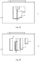
- the second plate element(3) may be arranged to include a second slot (13) having many portions ofdifferent heights as well as portions whose lowest and highest points are ondifferent horizontal levels. Further, the second plate element (13) may bearranged to include two or several separate slots (13) of different heightsand/or slots (13) being located at different horizontal levels - in view ofFigs. 2a and 2b, as if corresponding the portions of different heights of the some what complex single slot (13) of Fig. 2a .
- the first slot (12) is arranged to be at least as high as is the distance from the lowest point ofthe second slot (13) to the highest point of the second slot (13) - or from the lowest point of the slot (13) located lowest on the second plate element (3) to the highest point of the slot (13) located highest on the second plate element(3).
- the second slot (13) is arranged to be at least as wide as the first slot (12) - or, actually, each portion of the second slot (13) having a constant height is arranged to be at least as wide as the first slot (12). Incase there is more than one slot (13) in the second plate element (3), the samedimension criteria apply for each of the slots (13).
- the embodiment of only one slot (13) is obviously preferable.
- morethan one slot (13) is to be arranged in the second plate element (3), it ispreferable to arrange them quite close to each other.
- the embodiment shown in Fig. 2b is drawn basically just to demonstrate separationof the various portions of the second slot (13) of Fig. 2a ; according to apreferable embodiment of the invention, spacing of the slots (13) would betighter.
- the first and second plate elements (2, 3) of the platemechanism (1) of the invention are arranged movable with respect to each othersuch that at least portions of the plate elements (2, 3) move on differentplanes thus allowing an overlapping positioning of the first and second slots(12, 13).
- the plate elements (2, 3) are arranged as flat and movable on different planes in their entirety, but it is also possible to arrange the plate elements (2, 3) to have such aconstruction that only parts of the plate elements (2, 3) move on differentplanes, to allow for an overlapping positioning of the slots (12, 13).
- the first and second plate elements (2, 3) of Figs.3a and 3b are basically like those in Figs. 1-2 , the only difference being in the more complex shape of the second slot (13) of the second plate element (3).
- the basic components of the drive mechanism of Figs. 3a and 3b include anactuator (a motor) (4), a drive screw (5) and a nut (6) arranged in fixedconnection with the first plate element (2) via a connection element (7), whichgoes through an elongated hole (21) arranged in a frame element (20) thatsupports the plate construction (1).
- the second plate element (3) is alsosupported on the frame element (20) by pegs (8), which extend through the sameelongated hole (21).
- the frame element (20) further includes a guide groove(22), along which matching elements (24), arranged both to the first and secondplate elements (2, 3), are arranged to slide (matching elements of the firstplate element not being visible in the Figs 3a and 3b ).
- matching elements (24) arranged both to the first and secondplate elements (2, 3), are arranged to slide (matching elements of the firstplate element not being visible in the Figs 3a and 3b ).
- locking elements (9) are arranged, as well as near the lower edge of thesecond plate element (13) a block (11) of a desired dimension for keeping the plate elements (2, 3) at a desired distance from each other.
- the frame element(20) also includes an aperture (23) for the x-rays generated at the radiationsource to go through.
- the constructions which support the plate elements (2, 3)on the frame element (20) may include e.g. springs to keep the constructionstable yet at the same time not to cause such an amount of friction between the guide groove (22) and the matching elements (24) that the plate elements (2, 3)couldn't slide along the guide groove (22).
- An essential feature of the plate construction is that the second plate element (3) can be driven to a desired position within the operation range of the plate mechanism by using the single actuator(4) of to the construction, said actuator (4) being primarily arranged to move the first plate element (2) by the drive construction of the plate mechanism(1).
- the idea is to arrange the construction such that when moving the firstplate element (2) towards either end of its operation range, at some stageduring such a movement the plate elements (2, 3) will meet, directly or viasome construction arranged for this purpose, after which any further movementof the first plate element (2) in that direction will cause the second plateelement (3) to move in that same direction, too.
- another essential aspect of theconstruction is to include such a range within its operation range that, whenchanging the direction of movement of the first plate element (2) back towards the end opposite to the end towards which it was moving, the contact between the first and second plate elements (2, 3) will be broken and only the firstplate element (2) will be moving.
- the direction ofmovement of the first plate element (2) is changed, when having been in director indirect contact with the second plate element (3), there is always a distance within the operation range of the system within which the first plateelement (2) will move alone, i.e.
- the second plate element (3) can never move independently ofthe movement of the first plate element (2), whereas the first plate element(2) can move both independently without moving the second plate element (3) aswell as such that it moves the second plate element (3).
- the locking elements (9) of the pegs (8) are arranged of a distancefurther apart from each other than is the dimension of the first plate element(2) in the direction of movement of the first plate element (2), theconstruction will function as discussed above.
- a construction according to the invention makes itpossible to first drive the second plate element (3) to a desired position within the operation range of the mechanism, in order to arrange the secondslot (13) of the second plate element (3) to a desired position, after which the direction of movement of the first plate element (2) is reversed to drive the first slot (12) of the first plate element (2), now moving alone, to itsdesired position with respect to the position of the second plate element (3)to form an aperture which then will be defined by the overlapping slots (12,13) of the first and second plate elements (2, 3).
- the second plate element (3) will begin to move when an edge of the fist plateelement (2) meets either one of the pegs (8) (the locking elements (9)) beingfixed to the second plate element (3) but, obviously, there are a number ofother kinds of constructions by which the same function may be achieved.
- Theends of the operation range of the plate construction (1) may be defined by the ends of either the elongated slot (21) or the guide groove (22), or by both,for example.
- the distance the first plate element (2) is arranged to be moved corresponds at least the width of a single second slot (13) of the second plateelement (2), or the distance between the outermost slots (13) of the secondplate element (3).
- the first plate element (2) basically defining position of the beam limited by the construction, is driven by the actuator (4) and the second plate element (3)via the movements of the first plate element (2).
- the actuator (4) is to directly drivespecifically that plate element which defines position of the beam.
- x-ray beams can be created having a width defined by the first slot(12) of the first plate element (2) and the height and the horizontal positiondefined by the second slot (13) of the second plate element (3).
- Various kindsof such x-ray beams are needed e.g. in such dental radiology being based onscanning imaging techniques.
- slots (13) having heights of about 26 mm and about 22 mm, respectively, may be arranged in the second plate element (3).
- rectangular slots extending about 14 mmfrom the highest horizontal level of that of the slot arranged for panoramicimaging for adults may be arranged in view of panoramic scan of the dental archof the upper jaw only, and a corresponding slot in view of imaging the dentalarch of the lower jaw.
- corresponding slots may be arranged alsoin view of imaging the upper and lower jaws of children, and e.g. one in viewof a panoramic scan excluding the jawbone.
- the scope of the current invention is notlimited to specifically those forms and respective dimensions of aperturescreatable by the slots shown in Figs. 1-3 , even though already by e.g. such acollimator construction shown in Figs. 3a and 3b , one is able to cover a numberof typical x-ray beam sizes and beam positions typically used in a dental extraoral x-ray apparatus.
- Alternative or additional slot forms may be e.g.triangular ones enabling stepless adjustment of a dimension of the aperture,one having a height suitable for cephalometric imaging (imaging of the wholeskull) and apertures of more complex forms than a rectangle or a triangle, suchas ones having at least one curved edge.
- more than one slot may bearranged either to the first or second plate element, or to both of them, theremay be slots arranged not only next to each other but also on top of eachother, and such a construction is also possible where the second plate elementincludes only one slot and the first plate element a slot or slots of variousheights.
- a plate element may also be arranged to include both a more complextype aperture such as shown in Figs. 2a and 3a , for example, and additionallyone or more bare rectangles, for example. Further, either the first or thesecond plate element may be arranged to be the one being closer to the x-raysource.
- the plate construction according to the invention preferably comprises a means for detecting position of the first plate element within its operation range, even though the construction can be used even without such means as well by e.g. always starting a positioning-drive-sequenceof the plate elements by driving the plates to an end of the operation range ofthe construction. This done, one will always know where the plate elements are positioned upon starting positioning of the plates, and by using e.g. astepping motor one will be able to keep track of whereto the elements have beenmoved.
- Control system for the plate construction preferablyincludes pre-defined drive sequences for the plate elements, to be used inconnection with typical imaging modes applied by the imaging apparatus.
- the user interface may include the option of driving the actuator 'manually' as well, for fine-tuning purposes of positioning the beam, for example.
- the collimator according to the current invention is primarily designed for use as a so-called primary collimator in a dentalpanoramic x-ray apparatus.
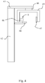
- a typical such apparatus is shown in Fig. 4 ,comprising a column-like body part (42) and a cantilever-type supportingelement (43) mounted on the upper end of the body part (42), possibly pivotallyso as to enable rotation of it with respect to the body part (42).
- an imaging arm often called a C-arm(45) is arranged for supporting an image data receiver (47) and an X-ray source(46).
- the mounting construction (44) for the C-arm (45) is designed to enablerotation of the C-arm (45) and horizontal movement of the rotation center ofthe C-arm (45).
- Attached to the column-like body (42) is arranged a patientsupport element (48).
- the apparatus may also be arranged to be used for e.g.cephalometric imaging by integrating a cephalometric imaging station to it (notshown in the Fig.), arranged at the end of a separate support arm mounted on the body part (42).
- the plate mechanism (1) is arranged within the cover of thex-ray source (46), as facing the image data receiver (47).
- the frame element(20) of the plate mechanism (1) may be arranged tobe a part of the x-ray tube housing such that, in view of Fig. 3a , for example,the first plate element (2) will be facing the x-ray source (46) and the secondplate element (3) the patient / the image data receiver (47).
- the cantilever-type supporting element(43) may also be mounted on a wall or a ceiling.
Landscapes
- Health & Medical Sciences (AREA)
- Life Sciences & Earth Sciences (AREA)
- Engineering & Computer Science (AREA)
- Physics & Mathematics (AREA)
- Medical Informatics (AREA)
- High Energy & Nuclear Physics (AREA)
- Radiology & Medical Imaging (AREA)
- Molecular Biology (AREA)
- Veterinary Medicine (AREA)
- Nuclear Medicine, Radiotherapy & Molecular Imaging (AREA)
- Optics & Photonics (AREA)
- Pathology (AREA)
- Public Health (AREA)
- Biomedical Technology (AREA)
- Heart & Thoracic Surgery (AREA)
- Biophysics (AREA)
- Surgery (AREA)
- Animal Behavior & Ethology (AREA)
- General Health & Medical Sciences (AREA)
- Spectroscopy & Molecular Physics (AREA)
- General Engineering & Computer Science (AREA)
- Dentistry (AREA)
- Oral & Maxillofacial Surgery (AREA)
- Apparatus For Radiation Diagnosis (AREA)
Claims (15)
- Construction pour limiter un faisceau de rayons X d'un appareil d'imagerie extra-orale dentaire, ladite construction comprenant un mécanisme de plaque (1) et un mécanisme d'entraînement incluant un actionneur (4) agencé pour déplacer au moins un élément de plaque (2, 3) compris dans le mécanisme (1), dans laquelle le mécanisme de plaque (1) comprend un premier élément de plaque (2) incluant au moins une première fente (12) pour limiter le faisceau de rayons X et un second élément de plaque (3) incluant au moins une seconde fente (13) pour limiter le faisceau de rayons X,
caractérisée en ce que ledit mécanisme d'entraînement est agencé pour déplacer directement ou indirectement ledit premier élément de plaque (2) indépendamment de l'emplacement dudit second élément de plaque (3) et ledit second élément de plaque (3) est agencé pour être déplacé uniquement par et en fonction des mouvements dudit premier élément de plaque (2), et en ce qu'au moins des portions desdits premier et second éléments de plaque (2, 3) sont agencées pour être mobiles sur différents plans de façon à permettre un positionnement desdites première et seconde fentes (12, 13) des premier et second éléments de plaque (2, 3) dans une position de chevauchement l'une par rapport à l'autre de façon à former une ouverture pour limiter le faisceau de rayons X, la forme de ladite ouverture étant ensuite limitée à la fois par la première fente (12) et la seconde fente (13). - Construction selon la revendication 1, caractérisée en ce que le mécanisme de plaque est agencé avec une plage de fonctionnement à l'intérieur de laquelle ledit premier élément de plaque (2) est agencé pour être mobile en va-et-vient dans une dimension et ledit second élément de plaque (3) est agencé pour être mobile tandis qu'il est entraîné par ledit premier élément de plaque (2) dans ces deux directions.
- Construction selon la revendication 1 ou 2, caractérisée en ce que le mécanisme de plaque (1) comprend des moyens agencés pour entraîner un contact direct ou indirect entre les premier et second éléments de plaque (2, 3) lorsque le premier élément de plaque (2) est entraîné vers une extrémité de la plage de fonctionnement du mécanisme de plaque (1) dans ladite dimension de mouvement agencée sur le mécanisme, et dans laquelle des dimensions et une construction des parties du mécanisme de plaque (1) sont agencées de sorte que lorsque la direction de mouvement du premier élément de plaque (2) est inversée, il y a une distance à l'intérieur de laquelle le premier élément de plaque (2) seul va se déplacer avant qu'un tel contact direct ou indirect soit créé entre lesdits premier et second éléments de plaque (2, 3) qui va entraîner le second élément de plaque (3) à se déplacer dans la direction de mouvement du premier élément de plaque (2).
- Construction selon l'une quelconque des revendications 1 à 3, caractérisée en ce que les formes des premier et second éléments de plaque (2, 3) sont agencées pour être au moins sensiblement plates et pour être mobiles en va-et-vient dans une dimension mais sur différents plans, et/ou en ce que les premier et second éléments de plaque (2, 3) sont agencés pour être supportés par un élément de cadre (20) via des constructions, qui permettent un déplacement desdits éléments de plaque (2, 3) par rapport audit élément de cadre (20).
- Construction selon la revendication 4, caractérisée en ce que ledit élément de cadre (20) inclut un trou allongé (21) à travers lequel des moyens de support (7, 8) pour à la fois lesdits premier et second éléments de plaque (2, 3) sont agencés pour s'étendre, et/ou en ce que ledit premier élément de plaque (2) est connecté audit mécanisme d'entraînement via un élément de connexion (7).
- Construction selon l'une quelconque des revendications 1 à 5, caractérisée en ce que ledit mécanisme de plaque (1) est supporté par un élément de cadre (20) sur lequel au moins une rainure, un rail ou une piste de guidage correspondante (21, 22) a été agencé et en ce que lesdits premier et second éléments de plaque (2, 3) du mécanisme de plaque (1) sont dotés d'un moyen (7, 8) agencé pour s'ajuster à ladite piste de guidage (21, 22) de sorte que le mouvement desdits éléments de plaque (2, 3) le long de ladite piste de guidage (21, 22) est autorisé.
- Construction selon la revendication 6, caractérisée en ce qu'un moyen (7, 8) agencé pour s'ajuster à ladite piste de guidage (21, 22) pour permettre le mouvement du second élément de plaque (3) le long de la piste de guidage (21, 22) comprend deux éléments (9) qui sont agencés à une distance plus éloignée l'un de l'autre que la dimension du premier élément de plaque (2) dans la direction de ladite piste de guidage (21, 22).
- Construction selon la revendication 7, caractérisée en ce que, en ce qui concerne la dimension, les premier et second éléments de plaque (2, 3) sont agencés pour être déplacés, ledit second élément de plaque (3) est agencé pour être plus large que ledit premier élément de plaque (2) et ledit premier élément de plaque (2) est agencé pour être déplacé à l'intérieur de la largeur couverte par le second élément de plaque (3).
- Construction selon l'une quelconque des revendications 1 à 8, caractérisée en ce que ladite première fente (12) du premier élément de plaque (2) est agencée pour être rectangulaire et sa dimension horizontale pour être sensiblement plus petite que sa dimension verticale, et sa dimension verticale pour être au moins aussi grande que celle de la portion la plus haute de la seconde fente (13) du second élément de plaque (3), ou au moins aussi grande que celle de la fente la plus haute (3) du second élément de plaque (3).
- Construction selon l'une quelconque des revendications 1 à 9, caractérisée en ce que ladite seconde fente (13) est agencée pour inclure au moins deux portions de différentes hauteurs et/ou au moins deux portions agencées sur des niveaux horizontaux différents et/ou au moins deux fentes rectangulaires de différentes hauteurs et/ou au moins deux fentes rectangulaires agencées sur des niveaux horizontaux différents, ou toute combinaison de ceux-ci comprenant au moins une fente incluant au moins deux portions de différentes hauteurs et au moins une fente rectangulaire.
- Construction selon l'une quelconque des revendications 1 à 10, caractérisée en ce que le mécanisme de plaque comprend une plage à l'intérieur de laquelle le premier élément de plaque (2) est déplacé par rapport au second élément de plaque (3), sans entraîner un contact entre les premier et second éléments de plaque (2, 3) tel que le second élément de plaque (3) commencerait à se déplacer dans la direction du mouvement du premier élément de plaque (2), laquelle plage est agencée pour être au moins aussi longue que la largeur de la seconde fente (13) du second élément de plaque (3), ou la distance entre les fentes (13) les plus à l'extérieur du second élément de plaque (3).
- Appareil d'imagerie à rayons X panoramique dentaire incluant une partie de corps (42) pour un élément de support de type porte-à-faux (43) monté au niveau de l'extrémité de ladite partie de corps (42), dans laquelle au niveau de ou à proximité de l'extrémité dudit élément de support (43) un bras d'imagerie (45) est agencé pour supporter un récepteur de données d'image (47) et une source de rayons X (46), caractérisé en ce que l'appareil inclut une construction de mécanisme de plaque (1) selon l'une quelconque des revendications 1 à 11, agencée pour limiter le faisceau de rayons X produit par ladite source de rayons X (46).
- Procédé pour limiter un faisceau de rayons X en conjonction avec l'imagerie extra-orale dentaire afin d'exposer une portion souhaitée de l'objet à imager seulement, dans lequel procédé au moins un élément de plaque (2, 3) d'un mécanisme de plaque (1) limitant le faisceau de rayons X est déplacé au moyen d'un mécanisme d'entraînement incluant un actionneur (4) de façon à produire un faisceau d'une forme spécifique, dans lequel deux éléments de plaque (2, 3) sont utilisés, parmi lesquels le premier élément de plaque (2) inclut une première fente (12) pour limiter le faisceau de rayons X et le second élément de plaque (3) inclut une seconde fente (13) pour limiter le faisceau de rayons X, caractérisé en ce que les éléments de plaque (2, 3) sont déplacés en utilisant le même seul actionneur (4) de telle manière que le premier élément de plaque (2) est déplacé par ledit mécanisme d'entraînement et indépendamment de l'emplacement dudit second élément de plaque (3), pendant que ledit second élément de plaque (3) est déplacé uniquement par et en fonction des mouvements du premier élément de plaque (2) et en ce qu'au moins des portions desdits premier et second éléments de plaque (2, 3) sont agencées pour être mobiles sur différents plans de façon à permettre un positionnement desdites première et seconde fentes (12, 13) des premier et second éléments de plaque (2, 3) dans une position de chevauchement l'une par rapport à l'autre de façon à former une ouverture pour limiter le faisceau de rayons X, la forme de ladite ouverture étant ainsi définie par l'ouverture combinée formée par lesdites première et seconde fentes (12, 13) desdits premier et second éléments de plaque (2, 3).
- Procédé selon la revendication 13, caractérisé en ce que ledit premier élément de plaque (2) est déplacé dans une dimension et ledit second élément de plaque (3) est déplacé par ledit premier élément de plaque (2) de sorte qu'au moins une partie du second élément de plaque (3) se déplace sur un plan différent mais parallèle au premier élément de plaque (2).
- Procédé selon la revendication 13 ou 14, caractérisé en ce que ledit second élément de plaque (3) est d'abord entraîné vers son emplacement souhaité en déplaçant ledit premier élément de plaque (2) et ledit premier élément de plaque (2) est ensuite entraîné vers son emplacement souhaité par l'action dudit mécanisme d'entraînement.
Applications Claiming Priority (2)
| Application Number | Priority Date | Filing Date | Title |
|---|---|---|---|
| FI20070221A FI122093B (fi) | 2007-03-19 | 2007-03-19 | Röntgensädekeilan rajaaminen hammaslääketieteellisen kuvantamisen yhteydessä |
| PCT/EP2008/052864 WO2008113715A1 (fr) | 2007-03-19 | 2008-03-11 | Limitation d'un faisceau de rayons x en conjonction avec un dispositif d'imagerie dentale |
Publications (2)
| Publication Number | Publication Date |
|---|---|
| EP2139398A1 EP2139398A1 (fr) | 2010-01-06 |
| EP2139398B1 true EP2139398B1 (fr) | 2019-06-19 |
Family
ID=37930023
Family Applications (1)
| Application Number | Title | Priority Date | Filing Date |
|---|---|---|---|
| EP08717611.1A Active EP2139398B1 (fr) | 2007-03-19 | 2008-03-11 | Limitation d'un faisceau de rayons x en conjonction avec un dispositif d'imagerie dentale |
Country Status (7)
| Country | Link |
|---|---|
| US (1) | US8130901B2 (fr) |
| EP (1) | EP2139398B1 (fr) |
| JP (1) | JP5220774B2 (fr) |
| KR (1) | KR101160791B1 (fr) |
| CN (1) | CN101668483B (fr) |
| FI (1) | FI122093B (fr) |
| WO (1) | WO2008113715A1 (fr) |
Families Citing this family (18)
| Publication number | Priority date | Publication date | Assignee | Title |
|---|---|---|---|---|
| FR2953707B1 (fr) * | 2009-12-16 | 2012-03-02 | Trophy | Appareil de radiologie dentaire fournissant une image cephalometrique et procede associe |
| US9004757B2 (en) * | 2010-03-24 | 2015-04-14 | PaloDEx Grou Oy | Systems, assemblies, computer readable media and methods for medical imaging |
| DE102010013591A1 (de) * | 2010-03-31 | 2011-10-06 | DüRR DENTAL AG | Röntgengerät und Verfahren zur Herstellung von Röntgenbildern für die zahnmedizinische oder kieferorthopädische Diagnostik |
| US8586955B2 (en) * | 2010-09-22 | 2013-11-19 | Ko Khee Tay | Apparatus and method for attenuating high energy radiation based on detected vehicle type |
| KR101175027B1 (ko) * | 2011-02-25 | 2012-08-17 | 이화여자대학교 산학협력단 | 카메라가 구비된 구강 내 엑스선 촬영장치 |
| CN102288626A (zh) * | 2011-07-18 | 2011-12-21 | 中国原子能科学研究院 | 中子织构测试设备 |
| US9208918B2 (en) * | 2012-11-16 | 2015-12-08 | Neurologica Corp. | Computerized tomography (CT) imaging system with multi-slit rotatable collimator |
| WO2015019232A2 (fr) * | 2013-08-08 | 2015-02-12 | Controlrad Systems Inc. | Système de réduction des rayons x |
| CN104545982A (zh) * | 2013-10-24 | 2015-04-29 | 南京普爱射线影像设备有限公司 | 一种四叶片牙科机限束器 |
| DE102014202330B3 (de) * | 2014-02-10 | 2015-06-03 | Siemens Aktiengesellschaft | Single Source DualEnergy mit zwei Filtern zur Röntgenspektrumsdifferenzierung bei Strahlerblenden mit Schlitzplatte |
| US9991014B1 (en) * | 2014-09-23 | 2018-06-05 | Daniel Gelbart | Fast positionable X-ray filter |
| WO2016087912A1 (fr) * | 2014-12-04 | 2016-06-09 | Trophy | Collimateur pour dispositifs d'imagerie dentaire extrabuccale céphalométrique |
| US20190021683A1 (en) * | 2015-12-23 | 2019-01-24 | Trophy | Method and Device for Creating a Cephalometric Image |
| ITUA20162102A1 (it) * | 2016-03-30 | 2017-09-30 | Cefla S C | Dispositivo di limitazione del fascio per apparecchiature radiografiche |
| US10714227B2 (en) * | 2016-06-06 | 2020-07-14 | Georgetown Rail Equipment Company | Rotating radiation shutter collimator |
| US10634797B2 (en) | 2017-07-07 | 2020-04-28 | International Business Machines Corporation | Real time X-ray dosimeter using diodes with variable thickness degrader |
| US11000256B2 (en) * | 2018-11-09 | 2021-05-11 | Palodex Group Oy | Calibrating an X-ray medical imaging device for cephalometric imaging |
| CN112971991B (zh) * | 2021-02-05 | 2022-11-11 | 上海电气集团股份有限公司 | 控制机械臂系统移动的方法及装置 |
Family Cites Families (17)
| Publication number | Priority date | Publication date | Assignee | Title |
|---|---|---|---|---|
| US4362422A (en) * | 1980-09-12 | 1982-12-07 | Zinkann Paul J | Grating fastener |
| DE3236082A1 (de) | 1982-09-29 | 1984-03-29 | Siemens AG, 1000 Berlin und 8000 München | Strahlenblende fuer ein roentgenuntersuchungsgeraet |
| FI89313C (fi) | 1985-09-13 | 1995-12-04 | Planmeca Oy | Styrsystem foer panoramatomografiroentgenanordning |
| DE3765558D1 (de) | 1986-02-28 | 1990-11-22 | Siemens Ag | Zahnaerztliches roentgendiagnostikgeraet zur erstellung von panorama-schichtaufnahmen vom kiefer eines patienten. |
| JPS63119939U (fr) | 1987-01-30 | 1988-08-03 | ||
| JPH0715524Y2 (ja) * | 1988-09-13 | 1995-04-12 | 株式会社モリタ製作所 | 歯科用パノラマ・セファロx線撮影装置 |
| DE4041296A1 (de) * | 1990-02-16 | 1991-08-22 | Siemens Ag | Primaerstrahlenblende |
| SE9003638D0 (sv) * | 1990-11-14 | 1990-11-14 | Siemens Elema Ab | Primaerstraaleblaendare foer ett roentgenroer |
| US5991362A (en) * | 1996-11-15 | 1999-11-23 | Xre Corporation | Adjustable opening X-ray mask |
| FR2770677B1 (fr) * | 1997-11-03 | 1999-12-24 | Ge Medical Syst Sa | Filtre de conformation de faisceau de rayon-x a surface variable et appareil d'imagerie pour rayon-x incorporant un tel filtre |
| JP3919048B2 (ja) * | 1998-09-02 | 2007-05-23 | 株式会社モリタ製作所 | 局所照射x線ct撮影装置 |
| FI110478B (fi) | 2001-05-29 | 2003-02-14 | Planmeca Oy | Menetelmä ja laitteisto sädekeilan rajaamiseksi |
| US20040066885A1 (en) * | 2002-07-08 | 2004-04-08 | Kabushiki Kaisha Toshiba | X-ray diagnosis apparatus |
| US7397903B2 (en) * | 2003-11-20 | 2008-07-08 | Ge Medical Systems Global Technology Company, Llc | Collimator and radiation irradiator |
| US7711085B2 (en) | 2005-04-11 | 2010-05-04 | J. Morita Manufacturing Corporation | Radiography apparatus with scout view function |
| FI118413B (fi) | 2005-04-11 | 2007-11-15 | Planmeca Oy | Tietokonetomografialaitteisto |
| FI20070850L (fi) * | 2005-04-11 | 2008-01-08 | Morita Mfg | Röntgensädekuva-anturi ja sitä käyttävä röntgensädekuvauslaite |
-
2007
- 2007-03-19 FI FI20070221A patent/FI122093B/fi active IP Right Grant
-
2008
- 2008-03-11 KR KR1020097021579A patent/KR101160791B1/ko not_active Expired - Fee Related
- 2008-03-11 JP JP2009553998A patent/JP5220774B2/ja not_active Expired - Fee Related
- 2008-03-11 CN CN200880013832XA patent/CN101668483B/zh not_active Expired - Fee Related
- 2008-03-11 EP EP08717611.1A patent/EP2139398B1/fr active Active
- 2008-03-11 US US12/531,747 patent/US8130901B2/en not_active Expired - Fee Related
- 2008-03-11 WO PCT/EP2008/052864 patent/WO2008113715A1/fr not_active Ceased
Non-Patent Citations (1)
| Title |
|---|
| None * |
Also Published As
| Publication number | Publication date |
|---|---|
| FI20070221A0 (fi) | 2007-03-19 |
| KR101160791B1 (ko) | 2012-06-27 |
| US8130901B2 (en) | 2012-03-06 |
| CN101668483B (zh) | 2012-02-15 |
| JP5220774B2 (ja) | 2013-06-26 |
| CN101668483A (zh) | 2010-03-10 |
| JP2010533507A (ja) | 2010-10-28 |
| US20100119036A1 (en) | 2010-05-13 |
| KR20090127423A (ko) | 2009-12-11 |
| EP2139398A1 (fr) | 2010-01-06 |
| FI20070221L (fi) | 2008-09-20 |
| FI122093B (fi) | 2011-08-31 |
| WO2008113715A1 (fr) | 2008-09-25 |
Similar Documents
| Publication | Publication Date | Title |
|---|---|---|
| US8130901B2 (en) | Limiting an X-ray beam in connection with dental imaging | |
| EP0632995B1 (fr) | Appareil de radiodiagnostic dentaire | |
| KR101780106B1 (ko) | 파노라마 방사선 촬영, 원거리 방사선 촬영 및 선택적으로 입체 cbct 방사선 촬영을 수행하기 위한 장치 | |
| EP1551302B1 (fr) | Appareil et proc d d'imagerie radiologique num rique en temps r el | |
| EP1721574B1 (fr) | Appareil combinant radiographie panoramique, cephalometrique et tomographie assistée par ordinateur | |
| US7236563B2 (en) | Combined panoramic and computed tomography photographing apparatus | |
| AU2014236805B2 (en) | X-ray scatter reducing device for use with 2D and 3D mammography | |
| KR101401927B1 (ko) | 치과용 파노라마 및 씨티 겸용 x선 촬영장치 | |
| CN110602993A (zh) | 多位置准直装置和x射线成像系统 | |
| KR20150088679A (ko) | Ct 촬영 장치 | |
| JP4388802B2 (ja) | 放射線ビームを限定する方法及び装置並びに同装置を備えた歯科用x線イメージング装置 | |
| US9750470B2 (en) | Aligning bite of X-ray device and X-ray device having the same | |
| US10937560B2 (en) | Beam-limiting device for radiographic apparatuses | |
| JP2007159987A (ja) | X線撮影装置 | |
| KR100872142B1 (ko) | 가변형 콜리메이터 | |
| EP4595892A1 (fr) | Appareil d'imagerie par rayons x | |
| CN121845624A (zh) | 一种大视野的cbct射源模块独立调节装置 | |
| JP2026514184A (ja) | モジュール式コンピュータ断層撮影検出器の構成 | |
| KR20210139303A (ko) | X선 영상장치 | |
| KR20200142710A (ko) | 방사선 촬영용 비접촉 두부 정렬장치 |
Legal Events
| Date | Code | Title | Description |
|---|---|---|---|
| PUAI | Public reference made under article 153(3) epc to a published international application that has entered the european phase |
Free format text: ORIGINAL CODE: 0009012 |
|
| 17P | Request for examination filed |
Effective date: 20091016 |
|
| AK | Designated contracting states |
Kind code of ref document: A1 Designated state(s): AT BE BG CH CY CZ DE DK EE ES FI FR GB GR HR HU IE IS IT LI LT LU LV MC MT NL NO PL PT RO SE SI SK TR |
|
| DAX | Request for extension of the european patent (deleted) | ||
| 17Q | First examination report despatched |
Effective date: 20160503 |
|
| REG | Reference to a national code |
Ref country code: DE Ref legal event code: R079 Ref document number: 602008060426 Country of ref document: DE Free format text: PREVIOUS MAIN CLASS: A61B0006060000 Ipc: G21K0001040000 |
|
| RIC1 | Information provided on ipc code assigned before grant |
Ipc: A61B 6/14 20060101ALI20181024BHEP Ipc: G21K 1/04 20060101AFI20181024BHEP Ipc: A61B 6/06 20060101ALI20181024BHEP |
|
| GRAP | Despatch of communication of intention to grant a patent |
Free format text: ORIGINAL CODE: EPIDOSNIGR1 |
|
| STAA | Information on the status of an ep patent application or granted ep patent |
Free format text: STATUS: GRANT OF PATENT IS INTENDED |
|
| INTG | Intention to grant announced |
Effective date: 20181207 |
|
| GRAS | Grant fee paid |
Free format text: ORIGINAL CODE: EPIDOSNIGR3 |
|
| GRAJ | Information related to disapproval of communication of intention to grant by the applicant or resumption of examination proceedings by the epo deleted |
Free format text: ORIGINAL CODE: EPIDOSDIGR1 |
|
| GRAL | Information related to payment of fee for publishing/printing deleted |
Free format text: ORIGINAL CODE: EPIDOSDIGR3 |
|
| STAA | Information on the status of an ep patent application or granted ep patent |
Free format text: STATUS: EXAMINATION IS IN PROGRESS |
|
| GRAR | Information related to intention to grant a patent recorded |
Free format text: ORIGINAL CODE: EPIDOSNIGR71 |
|
| STAA | Information on the status of an ep patent application or granted ep patent |
Free format text: STATUS: GRANT OF PATENT IS INTENDED |
|
| GRAA | (expected) grant |
Free format text: ORIGINAL CODE: 0009210 |
|
| STAA | Information on the status of an ep patent application or granted ep patent |
Free format text: STATUS: THE PATENT HAS BEEN GRANTED |
|
| INTC | Intention to grant announced (deleted) | ||
| INTG | Intention to grant announced |
Effective date: 20190509 |
|
| AK | Designated contracting states |
Kind code of ref document: B1 Designated state(s): AT BE BG CH CY CZ DE DK EE ES FI FR GB GR HR HU IE IS IT LI LT LU LV MC MT NL NO PL PT RO SE SI SK TR |
|
| REG | Reference to a national code |
Ref country code: GB Ref legal event code: FG4D |
|
| REG | Reference to a national code |
Ref country code: CH Ref legal event code: EP |
|
| REG | Reference to a national code |
Ref country code: IE Ref legal event code: FG4D |
|
| REG | Reference to a national code |
Ref country code: DE Ref legal event code: R096 Ref document number: 602008060426 Country of ref document: DE |
|
| REG | Reference to a national code |
Ref country code: AT Ref legal event code: REF Ref document number: 1146535 Country of ref document: AT Kind code of ref document: T Effective date: 20190715 |
|
| REG | Reference to a national code |
Ref country code: NL Ref legal event code: MP Effective date: 20190619 |
|
| PG25 | Lapsed in a contracting state [announced via postgrant information from national office to epo] |
Ref country code: HR Free format text: LAPSE BECAUSE OF FAILURE TO SUBMIT A TRANSLATION OF THE DESCRIPTION OR TO PAY THE FEE WITHIN THE PRESCRIBED TIME-LIMIT Effective date: 20190619 Ref country code: SE Free format text: LAPSE BECAUSE OF FAILURE TO SUBMIT A TRANSLATION OF THE DESCRIPTION OR TO PAY THE FEE WITHIN THE PRESCRIBED TIME-LIMIT Effective date: 20190619 Ref country code: LT Free format text: LAPSE BECAUSE OF FAILURE TO SUBMIT A TRANSLATION OF THE DESCRIPTION OR TO PAY THE FEE WITHIN THE PRESCRIBED TIME-LIMIT Effective date: 20190619 Ref country code: NO Free format text: LAPSE BECAUSE OF FAILURE TO SUBMIT A TRANSLATION OF THE DESCRIPTION OR TO PAY THE FEE WITHIN THE PRESCRIBED TIME-LIMIT Effective date: 20190919 Ref country code: FI Free format text: LAPSE BECAUSE OF FAILURE TO SUBMIT A TRANSLATION OF THE DESCRIPTION OR TO PAY THE FEE WITHIN THE PRESCRIBED TIME-LIMIT Effective date: 20190619 |
|
| REG | Reference to a national code |
Ref country code: LT Ref legal event code: MG4D |
|
| PG25 | Lapsed in a contracting state [announced via postgrant information from national office to epo] |
Ref country code: BG Free format text: LAPSE BECAUSE OF FAILURE TO SUBMIT A TRANSLATION OF THE DESCRIPTION OR TO PAY THE FEE WITHIN THE PRESCRIBED TIME-LIMIT Effective date: 20190919 Ref country code: LV Free format text: LAPSE BECAUSE OF FAILURE TO SUBMIT A TRANSLATION OF THE DESCRIPTION OR TO PAY THE FEE WITHIN THE PRESCRIBED TIME-LIMIT Effective date: 20190619 Ref country code: GR Free format text: LAPSE BECAUSE OF FAILURE TO SUBMIT A TRANSLATION OF THE DESCRIPTION OR TO PAY THE FEE WITHIN THE PRESCRIBED TIME-LIMIT Effective date: 20190920 |
|
| REG | Reference to a national code |
Ref country code: AT Ref legal event code: MK05 Ref document number: 1146535 Country of ref document: AT Kind code of ref document: T Effective date: 20190619 |
|
| PG25 | Lapsed in a contracting state [announced via postgrant information from national office to epo] |
Ref country code: PT Free format text: LAPSE BECAUSE OF FAILURE TO SUBMIT A TRANSLATION OF THE DESCRIPTION OR TO PAY THE FEE WITHIN THE PRESCRIBED TIME-LIMIT Effective date: 20191021 Ref country code: NL Free format text: LAPSE BECAUSE OF FAILURE TO SUBMIT A TRANSLATION OF THE DESCRIPTION OR TO PAY THE FEE WITHIN THE PRESCRIBED TIME-LIMIT Effective date: 20190619 Ref country code: SK Free format text: LAPSE BECAUSE OF FAILURE TO SUBMIT A TRANSLATION OF THE DESCRIPTION OR TO PAY THE FEE WITHIN THE PRESCRIBED TIME-LIMIT Effective date: 20190619 Ref country code: RO Free format text: LAPSE BECAUSE OF FAILURE TO SUBMIT A TRANSLATION OF THE DESCRIPTION OR TO PAY THE FEE WITHIN THE PRESCRIBED TIME-LIMIT Effective date: 20190619 Ref country code: CZ Free format text: LAPSE BECAUSE OF FAILURE TO SUBMIT A TRANSLATION OF THE DESCRIPTION OR TO PAY THE FEE WITHIN THE PRESCRIBED TIME-LIMIT Effective date: 20190619 Ref country code: EE Free format text: LAPSE BECAUSE OF FAILURE TO SUBMIT A TRANSLATION OF THE DESCRIPTION OR TO PAY THE FEE WITHIN THE PRESCRIBED TIME-LIMIT Effective date: 20190619 Ref country code: AT Free format text: LAPSE BECAUSE OF FAILURE TO SUBMIT A TRANSLATION OF THE DESCRIPTION OR TO PAY THE FEE WITHIN THE PRESCRIBED TIME-LIMIT Effective date: 20190619 |
|
| PG25 | Lapsed in a contracting state [announced via postgrant information from national office to epo] |
Ref country code: IS Free format text: LAPSE BECAUSE OF FAILURE TO SUBMIT A TRANSLATION OF THE DESCRIPTION OR TO PAY THE FEE WITHIN THE PRESCRIBED TIME-LIMIT Effective date: 20191019 Ref country code: ES Free format text: LAPSE BECAUSE OF FAILURE TO SUBMIT A TRANSLATION OF THE DESCRIPTION OR TO PAY THE FEE WITHIN THE PRESCRIBED TIME-LIMIT Effective date: 20190619 |
|
| PG25 | Lapsed in a contracting state [announced via postgrant information from national office to epo] |
Ref country code: TR Free format text: LAPSE BECAUSE OF FAILURE TO SUBMIT A TRANSLATION OF THE DESCRIPTION OR TO PAY THE FEE WITHIN THE PRESCRIBED TIME-LIMIT Effective date: 20190619 |
|
| PG25 | Lapsed in a contracting state [announced via postgrant information from national office to epo] |
Ref country code: DK Free format text: LAPSE BECAUSE OF FAILURE TO SUBMIT A TRANSLATION OF THE DESCRIPTION OR TO PAY THE FEE WITHIN THE PRESCRIBED TIME-LIMIT Effective date: 20190619 Ref country code: PL Free format text: LAPSE BECAUSE OF FAILURE TO SUBMIT A TRANSLATION OF THE DESCRIPTION OR TO PAY THE FEE WITHIN THE PRESCRIBED TIME-LIMIT Effective date: 20190619 |
|
| PG25 | Lapsed in a contracting state [announced via postgrant information from national office to epo] |
Ref country code: IS Free format text: LAPSE BECAUSE OF FAILURE TO SUBMIT A TRANSLATION OF THE DESCRIPTION OR TO PAY THE FEE WITHIN THE PRESCRIBED TIME-LIMIT Effective date: 20200224 |
|
| REG | Reference to a national code |
Ref country code: DE Ref legal event code: R097 Ref document number: 602008060426 Country of ref document: DE |
|
| PLBE | No opposition filed within time limit |
Free format text: ORIGINAL CODE: 0009261 |
|
| STAA | Information on the status of an ep patent application or granted ep patent |
Free format text: STATUS: NO OPPOSITION FILED WITHIN TIME LIMIT |
|
| PG2D | Information on lapse in contracting state deleted |
Ref country code: IS |
|
| 26N | No opposition filed |
Effective date: 20200603 |
|
| PG25 | Lapsed in a contracting state [announced via postgrant information from national office to epo] |
Ref country code: SI Free format text: LAPSE BECAUSE OF FAILURE TO SUBMIT A TRANSLATION OF THE DESCRIPTION OR TO PAY THE FEE WITHIN THE PRESCRIBED TIME-LIMIT Effective date: 20190619 |
|
| PG25 | Lapsed in a contracting state [announced via postgrant information from national office to epo] |
Ref country code: MC Free format text: LAPSE BECAUSE OF FAILURE TO SUBMIT A TRANSLATION OF THE DESCRIPTION OR TO PAY THE FEE WITHIN THE PRESCRIBED TIME-LIMIT Effective date: 20190619 |
|
| REG | Reference to a national code |
Ref country code: CH Ref legal event code: PL |
|
| REG | Reference to a national code |
Ref country code: BE Ref legal event code: MM Effective date: 20200331 |
|
| PG25 | Lapsed in a contracting state [announced via postgrant information from national office to epo] |
Ref country code: LU Free format text: LAPSE BECAUSE OF NON-PAYMENT OF DUE FEES Effective date: 20200311 |
|
| PG25 | Lapsed in a contracting state [announced via postgrant information from national office to epo] |
Ref country code: LI Free format text: LAPSE BECAUSE OF NON-PAYMENT OF DUE FEES Effective date: 20200331 Ref country code: CH Free format text: LAPSE BECAUSE OF NON-PAYMENT OF DUE FEES Effective date: 20200331 Ref country code: IE Free format text: LAPSE BECAUSE OF NON-PAYMENT OF DUE FEES Effective date: 20200311 |
|
| PG25 | Lapsed in a contracting state [announced via postgrant information from national office to epo] |
Ref country code: BE Free format text: LAPSE BECAUSE OF NON-PAYMENT OF DUE FEES Effective date: 20200331 |
|
| GBPC | Gb: european patent ceased through non-payment of renewal fee |
Effective date: 20200311 |
|
| PG25 | Lapsed in a contracting state [announced via postgrant information from national office to epo] |
Ref country code: GB Free format text: LAPSE BECAUSE OF NON-PAYMENT OF DUE FEES Effective date: 20200311 |
|
| PG25 | Lapsed in a contracting state [announced via postgrant information from national office to epo] |
Ref country code: MT Free format text: LAPSE BECAUSE OF FAILURE TO SUBMIT A TRANSLATION OF THE DESCRIPTION OR TO PAY THE FEE WITHIN THE PRESCRIBED TIME-LIMIT Effective date: 20190619 Ref country code: CY Free format text: LAPSE BECAUSE OF FAILURE TO SUBMIT A TRANSLATION OF THE DESCRIPTION OR TO PAY THE FEE WITHIN THE PRESCRIBED TIME-LIMIT Effective date: 20190619 |
|
| PGFP | Annual fee paid to national office [announced via postgrant information from national office to epo] |
Ref country code: FR Payment date: 20230222 Year of fee payment: 16 |
|
| PGFP | Annual fee paid to national office [announced via postgrant information from national office to epo] |
Ref country code: IT Payment date: 20230221 Year of fee payment: 16 Ref country code: DE Payment date: 20230221 Year of fee payment: 16 |
|
| REG | Reference to a national code |
Ref country code: DE Ref legal event code: R119 Ref document number: 602008060426 Country of ref document: DE |
|
| PG25 | Lapsed in a contracting state [announced via postgrant information from national office to epo] |
Ref country code: DE Free format text: LAPSE BECAUSE OF NON-PAYMENT OF DUE FEES Effective date: 20241001 |
|
| PG25 | Lapsed in a contracting state [announced via postgrant information from national office to epo] |
Ref country code: FR Free format text: LAPSE BECAUSE OF NON-PAYMENT OF DUE FEES Effective date: 20240331 |
|
| PG25 | Lapsed in a contracting state [announced via postgrant information from national office to epo] |
Ref country code: FR Free format text: LAPSE BECAUSE OF NON-PAYMENT OF DUE FEES Effective date: 20240331 Ref country code: DE Free format text: LAPSE BECAUSE OF NON-PAYMENT OF DUE FEES Effective date: 20241001 |
|
| PG25 | Lapsed in a contracting state [announced via postgrant information from national office to epo] |
Ref country code: IT Free format text: LAPSE BECAUSE OF NON-PAYMENT OF DUE FEES Effective date: 20240311 |