EP2139398B1 - Limiting an x-ray beam in connection with dental imaging - Google Patents
Limiting an x-ray beam in connection with dental imaging Download PDFInfo
- Publication number
- EP2139398B1 EP2139398B1 EP08717611.1A EP08717611A EP2139398B1 EP 2139398 B1 EP2139398 B1 EP 2139398B1 EP 08717611 A EP08717611 A EP 08717611A EP 2139398 B1 EP2139398 B1 EP 2139398B1
- Authority
- EP
- European Patent Office
- Prior art keywords
- plate
- plate element
- slot
- elements
- construction
- Prior art date
- Legal status (The legal status is an assumption and is not a legal conclusion. Google has not performed a legal analysis and makes no representation as to the accuracy of the status listed.)
- Active
Links
Images


Classifications
-
- A—HUMAN NECESSITIES
- A61—MEDICAL OR VETERINARY SCIENCE; HYGIENE
- A61B—DIAGNOSIS; SURGERY; IDENTIFICATION
- A61B6/00—Apparatus or devices for radiation diagnosis; Apparatus or devices for radiation diagnosis combined with radiation therapy equipment
- A61B6/50—Apparatus or devices for radiation diagnosis; Apparatus or devices for radiation diagnosis combined with radiation therapy equipment specially adapted for specific body parts; specially adapted for specific clinical applications
- A61B6/51—Apparatus or devices for radiation diagnosis; Apparatus or devices for radiation diagnosis combined with radiation therapy equipment specially adapted for specific body parts; specially adapted for specific clinical applications for dentistry
-
- A—HUMAN NECESSITIES
- A61—MEDICAL OR VETERINARY SCIENCE; HYGIENE
- A61B—DIAGNOSIS; SURGERY; IDENTIFICATION
- A61B6/00—Apparatus or devices for radiation diagnosis; Apparatus or devices for radiation diagnosis combined with radiation therapy equipment
- A61B6/06—Diaphragms
-
- G—PHYSICS
- G21—NUCLEAR PHYSICS; NUCLEAR ENGINEERING
- G21K—HANDLING OF PARTICLES OR IONISING RADIATION NOT OTHERWISE PROVIDED FOR; IRRADIATION DEVICES; GAMMA RAY OR X-RAY MICROSCOPES
- G21K1/00—Arrangements for handling particles or ionising radiation, e.g. focusing or moderating
- G21K1/02—Arrangements for handling particles or ionising radiation, e.g. focusing or moderating using diaphragms, collimators
-
- G—PHYSICS
- G21—NUCLEAR PHYSICS; NUCLEAR ENGINEERING
- G21K—HANDLING OF PARTICLES OR IONISING RADIATION NOT OTHERWISE PROVIDED FOR; IRRADIATION DEVICES; GAMMA RAY OR X-RAY MICROSCOPES
- G21K1/00—Arrangements for handling particles or ionising radiation, e.g. focusing or moderating
- G21K1/02—Arrangements for handling particles or ionising radiation, e.g. focusing or moderating using diaphragms, collimators
- G21K1/04—Arrangements for handling particles or ionising radiation, e.g. focusing or moderating using diaphragms, collimators using variable diaphragms, shutters, choppers
-
- G—PHYSICS
- G21—NUCLEAR PHYSICS; NUCLEAR ENGINEERING
- G21K—HANDLING OF PARTICLES OR IONISING RADIATION NOT OTHERWISE PROVIDED FOR; IRRADIATION DEVICES; GAMMA RAY OR X-RAY MICROSCOPES
- G21K1/00—Arrangements for handling particles or ionising radiation, e.g. focusing or moderating
- G21K1/02—Arrangements for handling particles or ionising radiation, e.g. focusing or moderating using diaphragms, collimators
- G21K1/04—Arrangements for handling particles or ionising radiation, e.g. focusing or moderating using diaphragms, collimators using variable diaphragms, shutters, choppers
- G21K1/046—Arrangements for handling particles or ionising radiation, e.g. focusing or moderating using diaphragms, collimators using variable diaphragms, shutters, choppers varying the contour of the field, e.g. multileaf collimators
Definitions
- the present invention relates to a method as defined in the preamble of claim 13 and to the construction as defined in the preamble of claim 1 for limiting an x-ray beam in connection with dental extra oral imaging.
- Dental radiography has been traditionally consideredincluding so-called intraoral imaging, which typically means imaging individualor a few teeth, extra oral imaging the most common imaging modes of which beingso-called panoramic imaging, which means producing a layer image, i.e. atomogram of the dental arch, and so-called cephalometric imaging, whichtypically means producing a transillumination image of the area of an entireskull.
- panoramic imaging which means producing a layer image, i.e. atomogram of the dental arch
- cephalometric imaging whichtypically means producing a transillumination image of the area of an entireskull.
- the same dental imaging apparatus is used for taking bothpanoramic and cephalometric images.
- use of the dental panoramic x-rayapparatus has expanded for producing various special images of different partsof the dental arch and even for 3D imaging.
- prior art dental panoramic x-ray imagingapparatuses include various kinds of adjustable and/orreplaceable plate constructions, i.e. collimators.
- Collimators according to prior art may constitute oneor more plates and/or the plates may include a number of different apertures.
- the x-ray beam must be limitedcorrespondingly by using an aperture of different shape and/or size.
- the space available in imaging apparatus often imposes certain restrictions asto the number of different apertures that can be arranged in a single plate aswell as to the number of plates as such that can be arranged into the apparatus.
- the arrangements needed allowing the replacement also involve certain problemsregarding convenience of use of the apparatus.
- a storage system mustbe arranged for the plates that are not in use at a given time.
- One prior art solution is to use e.g. a so-calledfour-plate-type collimator for limiting the beam both vertically and horizontally, in which each of the plates are driven by a separate actuator.
- the construction allows various beam sizes and forms to be provided for variousimaging modes.
- the use of several actuators leads to increased cost ofthe construction, to complex electronics for controlling the actuators and to a certain space requirement for the actuators.
- the object of the current invention is to reach newsolutions in view of the problems discussed above, especially in view ofcomplexity and space requirements of the collimator constructions.
- the methodof the invention is characterized by what is presented in the characterizingpart of claim 13, and the construction of the invention is characterized by what is presented in the characterizing part of claim 1.
- a fewpreferable embodiments of the invention are presented in the other claims.
- the current invention provides the advantage ofmaking it possible to adjust the shape of the aperture limiting an x-ray beamof an extra oral imaging apparatus in two dimensions at a reasonable cost by using a single collimator construction and one actuator only.
- the space the construction occupies in the imaging apparatus may bearranged to be reasonable yet x-ray beams of different shapes in two dimensionsmay be formed without having to arrange the plate elements replaceable.Reasonable number of components only is needed to realize the construction.
- Figs. 1a and 1b present a front view of plateelements of one embodiment of the invention. These figures show the platesonly, a drive mechanism of the plate mechanism according to the invention willbe discussed further below.
- the plate mechanism (1) comprises a first plate element (2) and a second plate element (3).
- the first plateelement (2) includes a first slot (12) and the second plate element (3)includes a second slot (13).
- the first slot (12) of the first plate element (2) is arranged to be rectangular and its horizontal dimension to be substantiallysmaller than its vertical dimension.
- the second slot (13) is arranged to havetwo portions of different heights.
- the construction is designed to makepossible arranging the slots (12, 13) of the first and second plate elements(2, 3) to lie on top of each other, by arranging at least portions of the plateelements (2, 3) movable on different planes.
- the first slot (12) is arranged tobe at least as high as is the distance from the lowest point of the second slot(13) to the highest point of the second slot (13).
- the second slot (13) isarranged to be at least as wide as the first slot (12) - or, actually, eachportion of the second slot (13) having a constant height is arranged to be atleast as wide as the first slot (12).
- Fig. 1b presents a front view of the plate mechanismof Fig. 1a with the plate elements (2, 3) in different respective positions.
- the locations of the slots (12, 13) is such that the width of the x-raybeam having passed the construction will be defined by the width of the firstslot (12) and the height by the second slot (13), now by another portion of thesecond slot (13) than in Fig. 1a .
- the x-ray beam will be lowerthan when the plate elements (2, 3) are position according to Fig. 1a .
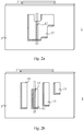
- the second plate element(3) may be arranged to include a second slot (13) having many portions ofdifferent heights as well as portions whose lowest and highest points are ondifferent horizontal levels. Further, the second plate element (13) may bearranged to include two or several separate slots (13) of different heightsand/or slots (13) being located at different horizontal levels - in view ofFigs. 2a and 2b, as if corresponding the portions of different heights of the some what complex single slot (13) of Fig. 2a .
- the first slot (12) is arranged to be at least as high as is the distance from the lowest point ofthe second slot (13) to the highest point of the second slot (13) - or from the lowest point of the slot (13) located lowest on the second plate element (3) to the highest point of the slot (13) located highest on the second plate element(3).
- the second slot (13) is arranged to be at least as wide as the first slot (12) - or, actually, each portion of the second slot (13) having a constant height is arranged to be at least as wide as the first slot (12). Incase there is more than one slot (13) in the second plate element (3), the samedimension criteria apply for each of the slots (13).
- the embodiment of only one slot (13) is obviously preferable.
- morethan one slot (13) is to be arranged in the second plate element (3), it ispreferable to arrange them quite close to each other.
- the embodiment shown in Fig. 2b is drawn basically just to demonstrate separationof the various portions of the second slot (13) of Fig. 2a ; according to apreferable embodiment of the invention, spacing of the slots (13) would betighter.
- the first and second plate elements (2, 3) of the platemechanism (1) of the invention are arranged movable with respect to each othersuch that at least portions of the plate elements (2, 3) move on differentplanes thus allowing an overlapping positioning of the first and second slots(12, 13).
- the plate elements (2, 3) are arranged as flat and movable on different planes in their entirety, but it is also possible to arrange the plate elements (2, 3) to have such aconstruction that only parts of the plate elements (2, 3) move on differentplanes, to allow for an overlapping positioning of the slots (12, 13).
- the first and second plate elements (2, 3) of Figs.3a and 3b are basically like those in Figs. 1-2 , the only difference being in the more complex shape of the second slot (13) of the second plate element (3).
- the basic components of the drive mechanism of Figs. 3a and 3b include anactuator (a motor) (4), a drive screw (5) and a nut (6) arranged in fixedconnection with the first plate element (2) via a connection element (7), whichgoes through an elongated hole (21) arranged in a frame element (20) thatsupports the plate construction (1).
- the second plate element (3) is alsosupported on the frame element (20) by pegs (8), which extend through the sameelongated hole (21).
- the frame element (20) further includes a guide groove(22), along which matching elements (24), arranged both to the first and secondplate elements (2, 3), are arranged to slide (matching elements of the firstplate element not being visible in the Figs 3a and 3b ).
- matching elements (24) arranged both to the first and secondplate elements (2, 3), are arranged to slide (matching elements of the firstplate element not being visible in the Figs 3a and 3b ).
- locking elements (9) are arranged, as well as near the lower edge of thesecond plate element (13) a block (11) of a desired dimension for keeping the plate elements (2, 3) at a desired distance from each other.
- the frame element(20) also includes an aperture (23) for the x-rays generated at the radiationsource to go through.
- the constructions which support the plate elements (2, 3)on the frame element (20) may include e.g. springs to keep the constructionstable yet at the same time not to cause such an amount of friction between the guide groove (22) and the matching elements (24) that the plate elements (2, 3)couldn't slide along the guide groove (22).
- An essential feature of the plate construction is that the second plate element (3) can be driven to a desired position within the operation range of the plate mechanism by using the single actuator(4) of to the construction, said actuator (4) being primarily arranged to move the first plate element (2) by the drive construction of the plate mechanism(1).
- the idea is to arrange the construction such that when moving the firstplate element (2) towards either end of its operation range, at some stageduring such a movement the plate elements (2, 3) will meet, directly or viasome construction arranged for this purpose, after which any further movementof the first plate element (2) in that direction will cause the second plateelement (3) to move in that same direction, too.
- another essential aspect of theconstruction is to include such a range within its operation range that, whenchanging the direction of movement of the first plate element (2) back towards the end opposite to the end towards which it was moving, the contact between the first and second plate elements (2, 3) will be broken and only the firstplate element (2) will be moving.
- the direction ofmovement of the first plate element (2) is changed, when having been in director indirect contact with the second plate element (3), there is always a distance within the operation range of the system within which the first plateelement (2) will move alone, i.e.
- the second plate element (3) can never move independently ofthe movement of the first plate element (2), whereas the first plate element(2) can move both independently without moving the second plate element (3) aswell as such that it moves the second plate element (3).
- the locking elements (9) of the pegs (8) are arranged of a distancefurther apart from each other than is the dimension of the first plate element(2) in the direction of movement of the first plate element (2), theconstruction will function as discussed above.
- a construction according to the invention makes itpossible to first drive the second plate element (3) to a desired position within the operation range of the mechanism, in order to arrange the secondslot (13) of the second plate element (3) to a desired position, after which the direction of movement of the first plate element (2) is reversed to drive the first slot (12) of the first plate element (2), now moving alone, to itsdesired position with respect to the position of the second plate element (3)to form an aperture which then will be defined by the overlapping slots (12,13) of the first and second plate elements (2, 3).
- the second plate element (3) will begin to move when an edge of the fist plateelement (2) meets either one of the pegs (8) (the locking elements (9)) beingfixed to the second plate element (3) but, obviously, there are a number ofother kinds of constructions by which the same function may be achieved.
- Theends of the operation range of the plate construction (1) may be defined by the ends of either the elongated slot (21) or the guide groove (22), or by both,for example.
- the distance the first plate element (2) is arranged to be moved corresponds at least the width of a single second slot (13) of the second plateelement (2), or the distance between the outermost slots (13) of the secondplate element (3).
- the first plate element (2) basically defining position of the beam limited by the construction, is driven by the actuator (4) and the second plate element (3)via the movements of the first plate element (2).
- the actuator (4) is to directly drivespecifically that plate element which defines position of the beam.
- x-ray beams can be created having a width defined by the first slot(12) of the first plate element (2) and the height and the horizontal positiondefined by the second slot (13) of the second plate element (3).
- Various kindsof such x-ray beams are needed e.g. in such dental radiology being based onscanning imaging techniques.
- slots (13) having heights of about 26 mm and about 22 mm, respectively, may be arranged in the second plate element (3).
- rectangular slots extending about 14 mmfrom the highest horizontal level of that of the slot arranged for panoramicimaging for adults may be arranged in view of panoramic scan of the dental archof the upper jaw only, and a corresponding slot in view of imaging the dentalarch of the lower jaw.
- corresponding slots may be arranged alsoin view of imaging the upper and lower jaws of children, and e.g. one in viewof a panoramic scan excluding the jawbone.
- the scope of the current invention is notlimited to specifically those forms and respective dimensions of aperturescreatable by the slots shown in Figs. 1-3 , even though already by e.g. such acollimator construction shown in Figs. 3a and 3b , one is able to cover a numberof typical x-ray beam sizes and beam positions typically used in a dental extraoral x-ray apparatus.
- Alternative or additional slot forms may be e.g.triangular ones enabling stepless adjustment of a dimension of the aperture,one having a height suitable for cephalometric imaging (imaging of the wholeskull) and apertures of more complex forms than a rectangle or a triangle, suchas ones having at least one curved edge.
- more than one slot may bearranged either to the first or second plate element, or to both of them, theremay be slots arranged not only next to each other but also on top of eachother, and such a construction is also possible where the second plate elementincludes only one slot and the first plate element a slot or slots of variousheights.
- a plate element may also be arranged to include both a more complextype aperture such as shown in Figs. 2a and 3a , for example, and additionallyone or more bare rectangles, for example. Further, either the first or thesecond plate element may be arranged to be the one being closer to the x-raysource.
- the plate construction according to the invention preferably comprises a means for detecting position of the first plate element within its operation range, even though the construction can be used even without such means as well by e.g. always starting a positioning-drive-sequenceof the plate elements by driving the plates to an end of the operation range ofthe construction. This done, one will always know where the plate elements are positioned upon starting positioning of the plates, and by using e.g. astepping motor one will be able to keep track of whereto the elements have beenmoved.
- Control system for the plate construction preferablyincludes pre-defined drive sequences for the plate elements, to be used inconnection with typical imaging modes applied by the imaging apparatus.
- the user interface may include the option of driving the actuator 'manually' as well, for fine-tuning purposes of positioning the beam, for example.
- the collimator according to the current invention is primarily designed for use as a so-called primary collimator in a dentalpanoramic x-ray apparatus.
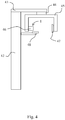
- a typical such apparatus is shown in Fig. 4 ,comprising a column-like body part (42) and a cantilever-type supportingelement (43) mounted on the upper end of the body part (42), possibly pivotallyso as to enable rotation of it with respect to the body part (42).
- an imaging arm often called a C-arm(45) is arranged for supporting an image data receiver (47) and an X-ray source(46).
- the mounting construction (44) for the C-arm (45) is designed to enablerotation of the C-arm (45) and horizontal movement of the rotation center ofthe C-arm (45).
- Attached to the column-like body (42) is arranged a patientsupport element (48).
- the apparatus may also be arranged to be used for e.g.cephalometric imaging by integrating a cephalometric imaging station to it (notshown in the Fig.), arranged at the end of a separate support arm mounted on the body part (42).
- the plate mechanism (1) is arranged within the cover of thex-ray source (46), as facing the image data receiver (47).
- the frame element(20) of the plate mechanism (1) may be arranged tobe a part of the x-ray tube housing such that, in view of Fig. 3a , for example,the first plate element (2) will be facing the x-ray source (46) and the secondplate element (3) the patient / the image data receiver (47).
- the cantilever-type supporting element(43) may also be mounted on a wall or a ceiling.
Landscapes
- Health & Medical Sciences (AREA)
- Life Sciences & Earth Sciences (AREA)
- Engineering & Computer Science (AREA)
- Physics & Mathematics (AREA)
- Medical Informatics (AREA)
- High Energy & Nuclear Physics (AREA)
- Radiology & Medical Imaging (AREA)
- Molecular Biology (AREA)
- Veterinary Medicine (AREA)
- Nuclear Medicine, Radiotherapy & Molecular Imaging (AREA)
- Optics & Photonics (AREA)
- Pathology (AREA)
- Public Health (AREA)
- Biomedical Technology (AREA)
- Heart & Thoracic Surgery (AREA)
- Biophysics (AREA)
- Surgery (AREA)
- Animal Behavior & Ethology (AREA)
- General Health & Medical Sciences (AREA)
- Spectroscopy & Molecular Physics (AREA)
- General Engineering & Computer Science (AREA)
- Dentistry (AREA)
- Oral & Maxillofacial Surgery (AREA)
- Apparatus For Radiation Diagnosis (AREA)
Description
- The present invention relates to a method as defined in the preamble of
claim 13 and to the construction as defined in the preamble ofclaim 1 for limiting an x-ray beam in connection with dental extra oral imaging. - Dental radiography has been traditionally consideredincluding so-called intraoral imaging, which typically means imaging individualor a few teeth, extra oral imaging the most common imaging modes of which beingso-called panoramic imaging, which means producing a layer image, i.e. atomogram of the dental arch, and so-called cephalometric imaging, whichtypically means producing a transillumination image of the area of an entireskull. Often the same dental imaging apparatus is used for taking bothpanoramic and cephalometric images. Recently, use of the dental panoramic x-rayapparatus has expanded for producing various special images of different partsof the dental arch and even for 3D imaging.
- When using the same x-ray apparatus for more than onemedical imaging purpose, it may be necessary to be able to limit the x-ray beamaccording to the requirements of the imaging mode in question. In other words,in view of radiation hygiene, one must be able to limit the beam to differentshapes and/or sizes. To this end, prior art dental panoramic x-ray imagingapparatuses, for example, include various kinds of adjustable and/orreplaceable plate constructions, i.e. collimators.
- Collimators according to prior art may constitute oneor more plates and/or the plates may include a number of different apertures.Typically, when a new exposure is to be made using a different imaging modethan that used in the previous one, the x-ray beam must be limitedcorrespondingly by using an aperture of different shape and/or size. However,the space available in imaging apparatus often imposes certain restrictions asto the number of different apertures that can be arranged in a single plate aswell as to the number of plates as such that can be arranged into the apparatus. In case the plates are arranged releasably connected and changeable,the arrangements needed allowing the replacement also involve certain problemsregarding convenience of use of the apparatus. Further, a storage system mustbe arranged for the plates that are not in use at a given time.
- One prior art solution is to use e.g. a so-calledfour-plate-type collimator for limiting the beam both vertically and horizontally, in which each of the plates are driven by a separate actuator.The construction allows various beam sizes and forms to be provided for variousimaging modes. However, the use of several actuators leads to increased cost ofthe construction, to complex electronics for controlling the actuators and to a certain space requirement for the actuators.
- Another kind of prior art plate mechanism is disclosedin Finnish patent application
894310 63-119939 - Further prior art plate mechanisms are disclosed inGerman patent publication 32 36 082 and
WO patent publication 02/097827 DE 32 36 082 , it enables a synchronizedmovement of the plates limiting the beam only and also offers no means toadjust the location of the aperture to be formed, only its width. Yet anotheraspect is that when a beam is limited by two plate elements arranged next to each other, should the aperture be adjustable e.g. in two perpendiculardirections, two such pairs of plate elements would be needed which, obviously,would lead to an even grater space requirement. - The object of the current invention is to reach newsolutions in view of the problems discussed above, especially in view ofcomplexity and space requirements of the collimator constructions. The methodof the invention is characterized by what is presented in the characterizingpart of
claim 13, and the construction of the invention is characterized by what is presented in the characterizing part ofclaim 1. A fewpreferable embodiments of the invention are presented in the other claims. - The current invention provides the advantage ofmaking it possible to adjust the shape of the aperture limiting an x-ray beamof an extra oral imaging apparatus in two dimensions at a reasonable cost by using a single collimator construction and one actuator only. By the combineduse of only one actuator, to operate the overlapping plate construction of the invention, the space the construction occupies in the imaging apparatus may bearranged to be reasonable yet x-ray beams of different shapes in two dimensionsmay be formed without having to arrange the plate elements replaceable.Reasonable number of components only is needed to realize the construction.
- Further collimator constructions in which the function of limiting the beam is based on operating a pair or pairs of solid collimator plates have been disclosed in publications
US 5,991,362 ,EP 0 485 742 A1 ,WO 2005/048845 A1 andWO 02/097827 A1 - In the following, the invention will be described inmore detail with the help of its certain preferable embodiments with referenceto the attached figures. Of the figures,
-
Fig. 1a presents a front view of plate elements of a first plate mechanism according to the invention, -
Fig. 1b presents a front view of the plate elementsof the first plate mechanism ofFig. 1a , the plate elements being positioned ina different respective position, -
Figs. 2a and 2b present front views of plate elementsof two other embodiments of the plate mechanism according to the invention, -
Figs. 3a and 3b present axiometric front and backviews of yet another plate mechanism according to the invention and -
Fig. 4 presents typical dental extra oral x-rayimaging apparatus in which the plate mechanism according to the invention isprimarily designed to be used. -
Figs. 1a and 1b present a front view of plateelements of one embodiment of the invention. These figures show the platesonly, a drive mechanism of the plate mechanism according to the invention willbe discussed further below. - The plate mechanism (1) according to
Fig. 1 comprisesa first plate element (2) and a second plate element (3). The first plateelement (2) includes a first slot (12) and the second plate element (3)includes a second slot (13). The first slot (12) of the first plate element (2)is arranged to be rectangular and its horizontal dimension to be substantiallysmaller than its vertical dimension. The second slot (13) is arranged to havetwo portions of different heights. The construction is designed to makepossible arranging the slots (12, 13) of the first and second plate elements(2, 3) to lie on top of each other, by arranging at least portions of the plateelements (2, 3) movable on different planes. The first slot (12) is arranged tobe at least as high as is the distance from the lowest point of the second slot(13) to the highest point of the second slot (13). The second slot (13) isarranged to be at least as wide as the first slot (12) - or, actually, eachportion of the second slot (13) having a constant height is arranged to be atleast as wide as the first slot (12). When an x-ray beam is directed towardsthis collimator construction, the form of the x-ray beam having passed theconstruction will be defined by the width of the first slot (12) and by the height of the second slot (13). -
Fig. 1b presents a front view of the plate mechanismofFig. 1a with the plate elements (2, 3) in different respective positions.Again, the locations of the slots (12, 13) is such that the width of the x-raybeam having passed the construction will be defined by the width of the firstslot (12) and the height by the second slot (13), now by another portion of thesecond slot (13) than inFig. 1a . As a result, the x-ray beam will be lowerthan when the plate elements (2, 3) are position according toFig. 1a . - As shown in
Figs. 2a and 2b , the second plate element(3) may be arranged to include a second slot (13) having many portions ofdifferent heights as well as portions whose lowest and highest points are ondifferent horizontal levels. Further, the second plate element (13) may bearranged to include two or several separate slots (13) of different heightsand/or slots (13) being located at different horizontal levels - in view ofFigs. 2a and 2b, as if corresponding the portions of different heights of the some what complex single slot (13) ofFig. 2a . Here, again, the first slot (12)is arranged to be at least as high as is the distance from the lowest point ofthe second slot (13) to the highest point of the second slot (13) - or from the lowest point of the slot (13) located lowest on the second plate element (3) to the highest point of the slot (13) located highest on the second plate element(3). Also, again, the second slot (13) is arranged to be at least as wide as the first slot (12) - or, actually, each portion of the second slot (13) having a constant height is arranged to be at least as wide as the first slot (12). Incase there is more than one slot (13) in the second plate element (3), the samedimension criteria apply for each of the slots (13). - In view of space occupied by the second plate element(3), the embodiment of only one slot (13) is obviously preferable. In case morethan one slot (13) is to be arranged in the second plate element (3), it ispreferable to arrange them quite close to each other. In this respect, the embodiment shown in
Fig. 2b is drawn basically just to demonstrate separationof the various portions of the second slot (13) ofFig. 2a ; according to apreferable embodiment of the invention, spacing of the slots (13) would betighter. - As will be discussed in more detail below in view ofFigs. 3a and 3b, the first and second plate elements (2, 3) of the platemechanism (1) of the invention are arranged movable with respect to each othersuch that at least portions of the plate elements (2, 3) move on differentplanes thus allowing an overlapping positioning of the first and second slots(12, 13). In the embodiments shown in the
Figs. 1-3 , the plate elements (2, 3)are arranged as flat and movable on different planes in their entirety, but it is also possible to arrange the plate elements (2, 3) to have such aconstruction that only parts of the plate elements (2, 3) move on differentplanes, to allow for an overlapping positioning of the slots (12, 13). - Above, the essential aspect of the invention ofoverlapping positioning of the slots limiting the beam has been discussed.Another essential feature of the invention regarding the drive mechanism of the plate construction (1) will now be discussed with respect to
Figs. 3a and 3b ,showing yet another embodiment of the invention. - The first and second plate elements (2, 3) of
Figs.3a and 3b are basically like those inFigs. 1-2 , the only difference being in the more complex shape of the second slot (13) of the second plate element (3).The basic components of the drive mechanism ofFigs. 3a and 3b include anactuator (a motor) (4), a drive screw (5) and a nut (6) arranged in fixedconnection with the first plate element (2) via a connection element (7), whichgoes through an elongated hole (21) arranged in a frame element (20) thatsupports the plate construction (1). The second plate element (3) is alsosupported on the frame element (20) by pegs (8), which extend through the sameelongated hole (21). The frame element (20) further includes a guide groove(22), along which matching elements (24), arranged both to the first and secondplate elements (2, 3), are arranged to slide (matching elements of the firstplate element not being visible in theFigs 3a and 3b ). At the ends of the pegs(8) of the second plate element (3) which extend through the elongated hole(21), locking elements (9) are arranged, as well as near the lower edge of thesecond plate element (13) a block (11) of a desired dimension for keeping the plate elements (2, 3) at a desired distance from each other. The frame element(20) also includes an aperture (23) for the x-rays generated at the radiationsource to go through. The constructions which support the plate elements (2, 3)on the frame element (20) may include e.g. springs to keep the constructionstable yet at the same time not to cause such an amount of friction between the guide groove (22) and the matching elements (24) that the plate elements (2, 3)couldn't slide along the guide groove (22). - An essential feature of the plate constructionaccording to the invention, in view of those embodiments of it shown in
Figs. 1-3 , is that the second plate element (3) can be driven to a desired position within the operation range of the plate mechanism by using the single actuator(4) of to the construction, said actuator (4) being primarily arranged to move the first plate element (2) by the drive construction of the plate mechanism(1). The idea is to arrange the construction such that when moving the firstplate element (2) towards either end of its operation range, at some stageduring such a movement the plate elements (2, 3) will meet, directly or viasome construction arranged for this purpose, after which any further movementof the first plate element (2) in that direction will cause the second plateelement (3) to move in that same direction, too. - Then, further, another essential aspect of theconstruction is to include such a range within its operation range that, whenchanging the direction of movement of the first plate element (2) back towards the end opposite to the end towards which it was moving, the contact between the first and second plate elements (2, 3) will be broken and only the firstplate element (2) will be moving. In other words, when the direction ofmovement of the first plate element (2) is changed, when having been in director indirect contact with the second plate element (3), there is always a distance within the operation range of the system within which the first plateelement (2) will move alone, i.e. without moving the second plate element (3),prior to the first plate element (2) again meeting the second plate element(3), or some construction being in contact with the second plate element (3),and starting to move the second plate element (3), now in the oppositedirection. Thus, the second plate element (3) can never move independently ofthe movement of the first plate element (2), whereas the first plate element(2) can move both independently without moving the second plate element (3) aswell as such that it moves the second plate element (3). In reference to
Fig.3b , when the locking elements (9) of the pegs (8) are arranged of a distancefurther apart from each other than is the dimension of the first plate element(2) in the direction of movement of the first plate element (2), theconstruction will function as discussed above. - A construction according to the invention makes itpossible to first drive the second plate element (3) to a desired position within the operation range of the mechanism, in order to arrange the secondslot (13) of the second plate element (3) to a desired position, after which the direction of movement of the first plate element (2) is reversed to drive the first slot (12) of the first plate element (2), now moving alone, to itsdesired position with respect to the position of the second plate element (3)to form an aperture which then will be defined by the overlapping slots (12,13) of the first and second plate elements (2, 3). In reference to the embodiments of the
Figs. 1-3 , considering the dimensions the first and secondplate elements (2, 3) are arranged to be moved, on different parallel planes,this functionality is reached by arranging said second plate element (3) to bewider than said first plate element (2) and said first plate element (2) to bemoved within the width covered by the second plate element (3). - Now, considering the construction shown in
Figs. 3a and3b , when the drive screw (5) is rotated by the actuator (4), the nut (6)moves axially on the drive screw (5) and thus also moves the first plateelement (2) being fixed to the nut (6) by the connecting element (7). Thedistance between the pegs (8) supporting the second plate element (3) isarranged to be greater than the width of the first plate element (2) so that,depending on the respective positions of the first and second plate elements(2, 3), either the first plate element (2) will move alone or it will also move the second plate element (3)- towards that end of the elongated opening (21) /the guide groove (22) the first plate element is moving. In this construction,the second plate element (3) will begin to move when an edge of the fist plateelement (2) meets either one of the pegs (8) (the locking elements (9)) beingfixed to the second plate element (3) but, obviously, there are a number ofother kinds of constructions by which the same function may be achieved. Theends of the operation range of the plate construction (1) may be defined by the ends of either the elongated slot (21) or the guide groove (22), or by both,for example. The distance the first plate element (2) is arranged to be movedcorresponds at least the width of a single second slot (13) of the second plateelement (2), or the distance between the outermost slots (13) of the secondplate element (3). - Above, a construction has been disclosed where the first plate element (2), basically defining position of the beam limited by the construction, is driven by the actuator (4) and the second plate element (3)via the movements of the first plate element (2). In principal, a contraryarrangement would be possible as well, but since correct positioning of the beam is basically more critical than a precisely exact height of it, apreferable alternative is to arrange the actuator (4) to directly drivespecifically that plate element which defines position of the beam.
- By the construction according to
Figs. 3a and 3b ,rectangular x-ray beams can be created having a width defined by the first slot(12) of the first plate element (2) and the height and the horizontal positiondefined by the second slot (13) of the second plate element (3). Various kindsof such x-ray beams are needed e.g. in such dental radiology being based onscanning imaging techniques. For example, in view of panoramic imaging scan ofdental arcs of adults on the first hand and children on the second, slots (13)having heights of about 26 mm and about 22 mm, respectively, may be arranged in the second plate element (3). Further, rectangular slots extending about 14 mmfrom the highest horizontal level of that of the slot arranged for panoramicimaging for adults may be arranged in view of panoramic scan of the dental archof the upper jaw only, and a corresponding slot in view of imaging the dentalarch of the lower jaw. Respectively, corresponding slots may be arranged alsoin view of imaging the upper and lower jaws of children, and e.g. one in viewof a panoramic scan excluding the jawbone. - Obviously, the scope of the current invention is notlimited to specifically those forms and respective dimensions of aperturescreatable by the slots shown in
Figs. 1-3 , even though already by e.g. such acollimator construction shown inFigs. 3a and 3b , one is able to cover a numberof typical x-ray beam sizes and beam positions typically used in a dental extraoral x-ray apparatus. Alternative or additional slot forms may be e.g.triangular ones enabling stepless adjustment of a dimension of the aperture,one having a height suitable for cephalometric imaging (imaging of the wholeskull) and apertures of more complex forms than a rectangle or a triangle, suchas ones having at least one curved edge. Further, more than one slot may bearranged either to the first or second plate element, or to both of them, theremay be slots arranged not only next to each other but also on top of eachother, and such a construction is also possible where the second plate elementincludes only one slot and the first plate element a slot or slots of variousheights. A plate element may also be arranged to include both a more complextype aperture such as shown inFigs. 2a and3a , for example, and additionallyone or more bare rectangles, for example. Further, either the first or thesecond plate element may be arranged to be the one being closer to the x-raysource. - The plate construction according to the inventionpreferably comprises a means for detecting position of the first plate element within its operation range, even though the construction can be used even without such means as well by e.g. always starting a positioning-drive-sequenceof the plate elements by driving the plates to an end of the operation range ofthe construction. This done, one will always know where the plate elements are positioned upon starting positioning of the plates, and by using e.g. astepping motor one will be able to keep track of whereto the elements have beenmoved.
- Control system for the plate construction preferablyincludes pre-defined drive sequences for the plate elements, to be used inconnection with typical imaging modes applied by the imaging apparatus. In addition, the user interface may include the option of driving the actuator 'manually' as well, for fine-tuning purposes of positioning the beam, for example.
- The collimator according to the current invention isprimarily designed for use as a so-called primary collimator in a dentalpanoramic x-ray apparatus. A typical such apparatus is shown in
Fig. 4 ,comprising a column-like body part (42) and a cantilever-type supportingelement (43) mounted on the upper end of the body part (42), possibly pivotallyso as to enable rotation of it with respect to the body part (42). At or near the end of said supporting element (43), an imaging arm often called a C-arm(45) is arranged for supporting an image data receiver (47) and an X-ray source(46). The mounting construction (44) for the C-arm (45) is designed to enablerotation of the C-arm (45) and horizontal movement of the rotation center ofthe C-arm (45). Attached to the column-like body (42) is arranged a patientsupport element (48). The apparatus may also be arranged to be used for e.g.cephalometric imaging by integrating a cephalometric imaging station to it (notshown in the Fig.), arranged at the end of a separate support arm mounted on the body part (42). The plate mechanism (1) is arranged within the cover of thex-ray source (46), as facing the image data receiver (47). The frame element(20) of the plate mechanism (1) according to the invention may be arranged tobe a part of the x-ray tube housing such that, in view ofFig. 3a , for example,the first plate element (2) will be facing the x-ray source (46) and the secondplate element (3) the patient / the image data receiver (47). Instead of beingmounted on a column-like body part (42), the cantilever-type supporting element(43) may also be mounted on a wall or a ceiling.
Claims (15)
- Construction for limiting an x-ray beam of a dental extra oral imaging apparatus, said construction comprising a plate mechanism (1) and a drive mechanism including an actuator (4) arranged to move at least one plate element (2, 3) comprised in the mechanism (1), wherein the plate mechanism (1) comprises a first plate element (2) including at least a first slot (12) for limiting the x-ray beam and a second plate element (3) including at least a second slot (13) for limiting the x-ray beam,
characterized in that said drive mechanism is arranged to directly or indirectly move said first plate element (2) independently of location of said second plate element (3) and said second plate element (3) is arranged to be moved solely by and dependent on the movements of said first plate element (2), and that at least portions of said first and second plate elements (2, 3) are arranged to be movable on different planes so as to enable positioning of said first and second slots (12, 13) of the first and second plate elements (2, 3) in an overlapping position with respect to each other so as to form an aperture for limiting the x-ray beam, the form of said aperture then being limited by both the first slot (12) and the second slot (13). - The construction according to claim 1, characterized in that the plate mechanism is arranged with an operation range within which said first plate element (2) is arranged to be movable back and forth in one dimension and said second plate element (3) is arranged to be movable as driven by said first plate element (2) in both of these directions.
- The construction according to claim 1 or 2, characterized in that the plate mechanism (1) comprises means arranged to cause a direct or indirect contact between the first and second plate elements (2, 3) when the first plate element (2) is driven towards an end of the operation range of the plate mechanism (1) in said dimension of movement arranged to the mechanism, and wherein dimensions and construction of the parts of the plate mechanism (1) are arranged such that when the direction of movement of the first plate element (2) is reversed, there is a distance within which the first plate element (2) alone will move before such a direct or indirect contact is created between said first and second plate elements (2, 3) that will cause the second plate element (3) to move in the direction of movement of the first plate element (2).
- The construction according to any one of the claims 1 - 3, characterized in that the shapes of the first and second plate elements (2, 3) are arranged to be at least substantially flat and to be movable back and forth in one dimension but on different planes, and/or that the first and second plate elements (2, 3) are arranged to be supported by a frame element (20) via constructions, which enable displacement of said plate elements (2, 3) with respect to said frame element (20).
- The construction according to claim 4, characterized in that said frame element (20) includes an elongated hole (21) through which supporting means (7, 8) for both said first and second plate elements (2, 3) are arranged to extend, and/or that said first plate element (2) is connected to said drive mechanism via a connection element (7).
- The construction according to any one of the claims 1 - 5, characterized in that said plate mechanism (1) is supported by a frame element (20) whereto at least one groove, rail or a corresponding guide track (21, 22) has been arranged and that said first and second plate elements (2, 3) of the plate mechanism (1) are provided with means (7, 8) arranged to fit to said guide track (21, 22) such that movement of said plate elements (2, 3) along said guide track (21, 22) is enabled.
- The construction according to claim 6, characterized in that means (7, 8) arranged to fit to said guide track (21, 22) to allow movement of the second plate element (3) along the guide track (21, 22) comprises two elements (9) which are arranged of a distance further apart from each other than is the dimension of the first plate element (2) in the direction of said guide track (21, 22).
- The construction according to claim 7, characterized in that, regarding the dimension the first and second plate elements (2, 3) are arranged to be moved, said second plate element (3) is arranged to be wider than said first plate element (2) and said first plate element (2) is arranged to be moved within the width covered by the second plate element (3).
- The construction according to any one of the claims 1 - 8, characterized in that said first slot (12) of the first plate element (2) is arranged to be rectangular and its horizontal dimension to be substantially smaller than its vertical dimension, and its vertical dimension to be at least as much as that of the highest portion of the second slot (13) of the second plate element (3), or at least as much as that of the highest slot (3) of the second plate element (3).
- The construction according to any one of the claims 1 - 9, characterized in that said second slot (13) is arranged to include at least two portions of different heights and/or at least two portions arranged on different horizontal levels and/or at least two rectangular slots of different heights and/or at least two rectangular slots arranged on different horizontal levels, or any combination of these comprising at least one slot including at least two portions of different heights and at least one rectangular slot.
- The construction according to any one of the claims 1 - 10, characterized in that the plate mechanism comprises a range within which the first plate element (2) is moved with respect to the second plate element (3), without causing such a contact being made between the first and second plate elements (2, 3) that the second plate element (3) would begin to move in the direction of movement of the first plate element (2), which range is arranged to be at least as long as is the width of the second slot (13) of the second plate element (3), or the distance between the outermost slots (13) of the second plate element (3).
- Dental panoramic x-ray imaging apparatus including a body part (42) for a cantilever-type supporting element (43) mounted at the end of said body part (42), in which at or near the end of said supporting element (43) is arranged an imaging arm (45) for supporting an image data receiver (47) and an X-ray source (46), characterized in that the apparatus includes a plate mechanism construction (1) according to any one of the claims 1 - 11 arranged for limiting the x-ray beam produced by said x-ray source (46).
- Method for limiting an x-ray beam in connection with dental extra oral imaging in order to expose a desired portion of the object to be imagined only, in which method at least one plate element (2, 3) of a plate mechanism (1) limiting the x-ray beam is moved by means of a drive mechanism including an actuator (4) so as to produce a beam of a specific form, wherein two plate elements (2, 3) are used, out of which the first plate element (2) includes a first slot (12) for limiting the x-ray beam and the second plate element (3) includes a second slot (13) for limiting the x-ray beam, characterized in that the plate elements (2, 3) are moved by use of the same single actuator (4) in such a manner that the first plate element (2) is moved by said drive mechanism and independently of location of said second plate element (3), whereas said second plate element (3) is moved solely by and dependent on the movements of the first plate element (2) and that at least portions of said first and second plate elements (2, 3) are arranged to be movable on different planes so as to enable positioning of said first and second slots (12, 13) of the first and second plate elements (2,3) in an overlapping position with respect to each other so as to form an aperture to limit the x-ray beam, the form of said aperture thus becoming defined by the combined aperture formed by said first and second slots (12, 13) of the first and second plate elements (2, 3).
- The method according to claim 13, characterized in that said first plate element (2) is moved in one dimension and said second plate element (3) is moved by said first plate element (2) such that at least part of the second plate element (3) moves on a different but parallel plane than said first plate element (2).
- The method according to claim 13 or 14, characterized in that said second plate element (3) is first driven to its desired location by moving said first plate element (2) and said first plate element (2) is then driven to its desired location by the action of said drive mechanism.
Applications Claiming Priority (2)
| Application Number | Priority Date | Filing Date | Title |
|---|---|---|---|
| FI20070221A FI122093B (en) | 2007-03-19 | 2007-03-19 | Delimitation of an X-ray cone in connection with dental imaging |
| PCT/EP2008/052864 WO2008113715A1 (en) | 2007-03-19 | 2008-03-11 | Limiting an x-ray beam in connection with dental imaging |
Publications (2)
| Publication Number | Publication Date |
|---|---|
| EP2139398A1 EP2139398A1 (en) | 2010-01-06 |
| EP2139398B1 true EP2139398B1 (en) | 2019-06-19 |
Family
ID=37930023
Family Applications (1)
| Application Number | Title | Priority Date | Filing Date |
|---|---|---|---|
| EP08717611.1A Active EP2139398B1 (en) | 2007-03-19 | 2008-03-11 | Limiting an x-ray beam in connection with dental imaging |
Country Status (7)
| Country | Link |
|---|---|
| US (1) | US8130901B2 (en) |
| EP (1) | EP2139398B1 (en) |
| JP (1) | JP5220774B2 (en) |
| KR (1) | KR101160791B1 (en) |
| CN (1) | CN101668483B (en) |
| FI (1) | FI122093B (en) |
| WO (1) | WO2008113715A1 (en) |
Families Citing this family (18)
| Publication number | Priority date | Publication date | Assignee | Title |
|---|---|---|---|---|
| FR2953707B1 (en) * | 2009-12-16 | 2012-03-02 | Trophy | DENTAL RADIOLOGY APPARATUS PROVIDING A CEPHALOMETRIC IMAGE AND ASSOCIATED METHOD |
| US9004757B2 (en) * | 2010-03-24 | 2015-04-14 | PaloDEx Grou Oy | Systems, assemblies, computer readable media and methods for medical imaging |
| DE102010013591A1 (en) * | 2010-03-31 | 2011-10-06 | DüRR DENTAL AG | X-ray apparatus and method for producing X-ray images for dental or orthodontic diagnostics |
| US8586955B2 (en) * | 2010-09-22 | 2013-11-19 | Ko Khee Tay | Apparatus and method for attenuating high energy radiation based on detected vehicle type |
| KR101175027B1 (en) * | 2011-02-25 | 2012-08-17 | 이화여자대학교 산학협력단 | X-ray panorama imaging apparatus having a camera in oral cavity |
| CN102288626A (en) * | 2011-07-18 | 2011-12-21 | 中国原子能科学研究院 | Neutron texture testing equipment |
| US9208918B2 (en) * | 2012-11-16 | 2015-12-08 | Neurologica Corp. | Computerized tomography (CT) imaging system with multi-slit rotatable collimator |
| WO2015019232A2 (en) * | 2013-08-08 | 2015-02-12 | Controlrad Systems Inc. | X-ray reduction system |
| CN104545982A (en) * | 2013-10-24 | 2015-04-29 | 南京普爱射线影像设备有限公司 | Four-blade beam limiter of dentistry instrument |
| DE102014202330B3 (en) * | 2014-02-10 | 2015-06-03 | Siemens Aktiengesellschaft | Single Source DualEnergy with two filters for X-ray spectrum differentiation on radiator apertures with slotted plate |
| US9991014B1 (en) * | 2014-09-23 | 2018-06-05 | Daniel Gelbart | Fast positionable X-ray filter |
| WO2016087912A1 (en) * | 2014-12-04 | 2016-06-09 | Trophy | Collimator for cephalometric extra oral dental imaging devices |
| US20190021683A1 (en) * | 2015-12-23 | 2019-01-24 | Trophy | Method and Device for Creating a Cephalometric Image |
| ITUA20162102A1 (en) * | 2016-03-30 | 2017-09-30 | Cefla S C | BEAM RESTRICTION DEVICE FOR RADIOGRAPHIC EQUIPMENT |
| US10714227B2 (en) * | 2016-06-06 | 2020-07-14 | Georgetown Rail Equipment Company | Rotating radiation shutter collimator |
| US10634797B2 (en) | 2017-07-07 | 2020-04-28 | International Business Machines Corporation | Real time X-ray dosimeter using diodes with variable thickness degrader |
| US11000256B2 (en) * | 2018-11-09 | 2021-05-11 | Palodex Group Oy | Calibrating an X-ray medical imaging device for cephalometric imaging |
| CN112971991B (en) * | 2021-02-05 | 2022-11-11 | 上海电气集团股份有限公司 | Method and device for controlling movement of mechanical arm system |
Family Cites Families (17)
| Publication number | Priority date | Publication date | Assignee | Title |
|---|---|---|---|---|
| US4362422A (en) * | 1980-09-12 | 1982-12-07 | Zinkann Paul J | Grating fastener |
| DE3236082A1 (en) | 1982-09-29 | 1984-03-29 | Siemens AG, 1000 Berlin und 8000 München | Radiation diaphragm for an X-ray examination apparatus |
| FI89313C (en) | 1985-09-13 | 1995-12-04 | Planmeca Oy | Styrsystem Foer panoramatomografiroentgenanordning |
| DE3765558D1 (en) | 1986-02-28 | 1990-11-22 | Siemens Ag | DENTAL X-RAY DIAGNOSTIC DEVICE FOR CREATING PANORAMIC LAYING FROM A PATIENT'S JAW. |
| JPS63119939U (en) | 1987-01-30 | 1988-08-03 | ||
| JPH0715524Y2 (en) * | 1988-09-13 | 1995-04-12 | 株式会社モリタ製作所 | Dental panoramic cephalography system |
| DE4041296A1 (en) * | 1990-02-16 | 1991-08-22 | Siemens Ag | PRIMARY RADIATION |
| SE9003638D0 (en) * | 1990-11-14 | 1990-11-14 | Siemens Elema Ab | PRIMARY RADIATION BLENDERS FOR A ROUND GENEROUS |
| US5991362A (en) * | 1996-11-15 | 1999-11-23 | Xre Corporation | Adjustable opening X-ray mask |
| FR2770677B1 (en) * | 1997-11-03 | 1999-12-24 | Ge Medical Syst Sa | X-RAY BEAM CONFORMATION FILTER WITH VARIABLE SURFACE AND X-RAY IMAGING APPARATUS INCORPORATING SUCH A FILTER |
| JP3919048B2 (en) * | 1998-09-02 | 2007-05-23 | 株式会社モリタ製作所 | Local irradiation X-ray CT imaging system |
| FI110478B (en) | 2001-05-29 | 2003-02-14 | Planmeca Oy | Method and apparatus for delimiting a radiation beam |
| US20040066885A1 (en) * | 2002-07-08 | 2004-04-08 | Kabushiki Kaisha Toshiba | X-ray diagnosis apparatus |
| US7397903B2 (en) * | 2003-11-20 | 2008-07-08 | Ge Medical Systems Global Technology Company, Llc | Collimator and radiation irradiator |
| US7711085B2 (en) | 2005-04-11 | 2010-05-04 | J. Morita Manufacturing Corporation | Radiography apparatus with scout view function |
| FI118413B (en) | 2005-04-11 | 2007-11-15 | Planmeca Oy | Computed tomography system |
| FI20070850L (en) * | 2005-04-11 | 2008-01-08 | Morita Mfg | An X-ray image sensor and an X-ray imaging device using it |
-
2007
- 2007-03-19 FI FI20070221A patent/FI122093B/en active IP Right Grant
-
2008
- 2008-03-11 KR KR1020097021579A patent/KR101160791B1/en not_active Expired - Fee Related
- 2008-03-11 JP JP2009553998A patent/JP5220774B2/en not_active Expired - Fee Related
- 2008-03-11 CN CN200880013832XA patent/CN101668483B/en not_active Expired - Fee Related
- 2008-03-11 EP EP08717611.1A patent/EP2139398B1/en active Active
- 2008-03-11 US US12/531,747 patent/US8130901B2/en not_active Expired - Fee Related
- 2008-03-11 WO PCT/EP2008/052864 patent/WO2008113715A1/en not_active Ceased
Non-Patent Citations (1)
| Title |
|---|
| None * |
Also Published As
| Publication number | Publication date |
|---|---|
| FI20070221A0 (en) | 2007-03-19 |
| KR101160791B1 (en) | 2012-06-27 |
| US8130901B2 (en) | 2012-03-06 |
| CN101668483B (en) | 2012-02-15 |
| JP5220774B2 (en) | 2013-06-26 |
| CN101668483A (en) | 2010-03-10 |
| JP2010533507A (en) | 2010-10-28 |
| US20100119036A1 (en) | 2010-05-13 |
| KR20090127423A (en) | 2009-12-11 |
| EP2139398A1 (en) | 2010-01-06 |
| FI20070221L (en) | 2008-09-20 |
| FI122093B (en) | 2011-08-31 |
| WO2008113715A1 (en) | 2008-09-25 |
Similar Documents
| Publication | Publication Date | Title |
|---|---|---|
| US8130901B2 (en) | Limiting an X-ray beam in connection with dental imaging | |
| EP0632995B1 (en) | Dental X-ray diagnostic device | |
| KR101780106B1 (en) | Apparatus for acquiring panoramic, teleradiographic and optionally volumetric cbct radiographies | |
| EP1551302B1 (en) | Real-time digital x-ray imaging apparatus and method | |
| EP1721574B1 (en) | Combined panoramic, CT (computed tomography) and cephalometric X-ray apparatus | |
| US7236563B2 (en) | Combined panoramic and computed tomography photographing apparatus | |
| AU2014236805B2 (en) | X-ray scatter reducing device for use with 2D and 3D mammography | |
| KR101401927B1 (en) | X-ray photographing apparatus combining panorama and ct for dental clinic | |
| CN110602993A (en) | Multi-position collimation device and X-ray imaging system | |
| KR20150088679A (en) | Apparatus for Obtaining Computed Tomography | |
| JP4388802B2 (en) | Method and apparatus for limiting a radiation beam and dental X-ray imaging apparatus provided with the same | |
| US9750470B2 (en) | Aligning bite of X-ray device and X-ray device having the same | |
| US10937560B2 (en) | Beam-limiting device for radiographic apparatuses | |
| JP2007159987A (en) | X-ray equipment | |
| KR100872142B1 (en) | Variable collimator | |
| EP4595892A1 (en) | X-ray imaging apparatus | |
| CN121845624A (en) | An independent adjustment device for a large field of view CBCT source module | |
| JP2026514184A (en) | Configuration of a modular computed tomography detector | |
| KR20210139303A (en) | X-ray imaging device | |
| KR20200142710A (en) | Non-contact head arragement appratus for radiography |
Legal Events
| Date | Code | Title | Description |
|---|---|---|---|
| PUAI | Public reference made under article 153(3) epc to a published international application that has entered the european phase |
Free format text: ORIGINAL CODE: 0009012 |
|
| 17P | Request for examination filed |
Effective date: 20091016 |
|
| AK | Designated contracting states |
Kind code of ref document: A1 Designated state(s): AT BE BG CH CY CZ DE DK EE ES FI FR GB GR HR HU IE IS IT LI LT LU LV MC MT NL NO PL PT RO SE SI SK TR |
|
| DAX | Request for extension of the european patent (deleted) | ||
| 17Q | First examination report despatched |
Effective date: 20160503 |
|
| REG | Reference to a national code |
Ref country code: DE Ref legal event code: R079 Ref document number: 602008060426 Country of ref document: DE Free format text: PREVIOUS MAIN CLASS: A61B0006060000 Ipc: G21K0001040000 |
|
| RIC1 | Information provided on ipc code assigned before grant |
Ipc: A61B 6/14 20060101ALI20181024BHEP Ipc: G21K 1/04 20060101AFI20181024BHEP Ipc: A61B 6/06 20060101ALI20181024BHEP |
|
| GRAP | Despatch of communication of intention to grant a patent |
Free format text: ORIGINAL CODE: EPIDOSNIGR1 |
|
| STAA | Information on the status of an ep patent application or granted ep patent |
Free format text: STATUS: GRANT OF PATENT IS INTENDED |
|
| INTG | Intention to grant announced |
Effective date: 20181207 |
|
| GRAS | Grant fee paid |
Free format text: ORIGINAL CODE: EPIDOSNIGR3 |
|
| GRAJ | Information related to disapproval of communication of intention to grant by the applicant or resumption of examination proceedings by the epo deleted |
Free format text: ORIGINAL CODE: EPIDOSDIGR1 |
|
| GRAL | Information related to payment of fee for publishing/printing deleted |
Free format text: ORIGINAL CODE: EPIDOSDIGR3 |
|
| STAA | Information on the status of an ep patent application or granted ep patent |
Free format text: STATUS: EXAMINATION IS IN PROGRESS |
|
| GRAR | Information related to intention to grant a patent recorded |
Free format text: ORIGINAL CODE: EPIDOSNIGR71 |
|
| STAA | Information on the status of an ep patent application or granted ep patent |
Free format text: STATUS: GRANT OF PATENT IS INTENDED |
|
| GRAA | (expected) grant |
Free format text: ORIGINAL CODE: 0009210 |
|
| STAA | Information on the status of an ep patent application or granted ep patent |
Free format text: STATUS: THE PATENT HAS BEEN GRANTED |
|
| INTC | Intention to grant announced (deleted) | ||
| INTG | Intention to grant announced |
Effective date: 20190509 |
|
| AK | Designated contracting states |
Kind code of ref document: B1 Designated state(s): AT BE BG CH CY CZ DE DK EE ES FI FR GB GR HR HU IE IS IT LI LT LU LV MC MT NL NO PL PT RO SE SI SK TR |
|
| REG | Reference to a national code |
Ref country code: GB Ref legal event code: FG4D |
|
| REG | Reference to a national code |
Ref country code: CH Ref legal event code: EP |
|
| REG | Reference to a national code |
Ref country code: IE Ref legal event code: FG4D |
|
| REG | Reference to a national code |
Ref country code: DE Ref legal event code: R096 Ref document number: 602008060426 Country of ref document: DE |
|
| REG | Reference to a national code |
Ref country code: AT Ref legal event code: REF Ref document number: 1146535 Country of ref document: AT Kind code of ref document: T Effective date: 20190715 |
|
| REG | Reference to a national code |
Ref country code: NL Ref legal event code: MP Effective date: 20190619 |
|
| PG25 | Lapsed in a contracting state [announced via postgrant information from national office to epo] |
Ref country code: HR Free format text: LAPSE BECAUSE OF FAILURE TO SUBMIT A TRANSLATION OF THE DESCRIPTION OR TO PAY THE FEE WITHIN THE PRESCRIBED TIME-LIMIT Effective date: 20190619 Ref country code: SE Free format text: LAPSE BECAUSE OF FAILURE TO SUBMIT A TRANSLATION OF THE DESCRIPTION OR TO PAY THE FEE WITHIN THE PRESCRIBED TIME-LIMIT Effective date: 20190619 Ref country code: LT Free format text: LAPSE BECAUSE OF FAILURE TO SUBMIT A TRANSLATION OF THE DESCRIPTION OR TO PAY THE FEE WITHIN THE PRESCRIBED TIME-LIMIT Effective date: 20190619 Ref country code: NO Free format text: LAPSE BECAUSE OF FAILURE TO SUBMIT A TRANSLATION OF THE DESCRIPTION OR TO PAY THE FEE WITHIN THE PRESCRIBED TIME-LIMIT Effective date: 20190919 Ref country code: FI Free format text: LAPSE BECAUSE OF FAILURE TO SUBMIT A TRANSLATION OF THE DESCRIPTION OR TO PAY THE FEE WITHIN THE PRESCRIBED TIME-LIMIT Effective date: 20190619 |
|
| REG | Reference to a national code |
Ref country code: LT Ref legal event code: MG4D |
|
| PG25 | Lapsed in a contracting state [announced via postgrant information from national office to epo] |
Ref country code: BG Free format text: LAPSE BECAUSE OF FAILURE TO SUBMIT A TRANSLATION OF THE DESCRIPTION OR TO PAY THE FEE WITHIN THE PRESCRIBED TIME-LIMIT Effective date: 20190919 Ref country code: LV Free format text: LAPSE BECAUSE OF FAILURE TO SUBMIT A TRANSLATION OF THE DESCRIPTION OR TO PAY THE FEE WITHIN THE PRESCRIBED TIME-LIMIT Effective date: 20190619 Ref country code: GR Free format text: LAPSE BECAUSE OF FAILURE TO SUBMIT A TRANSLATION OF THE DESCRIPTION OR TO PAY THE FEE WITHIN THE PRESCRIBED TIME-LIMIT Effective date: 20190920 |
|
| REG | Reference to a national code |
Ref country code: AT Ref legal event code: MK05 Ref document number: 1146535 Country of ref document: AT Kind code of ref document: T Effective date: 20190619 |
|
| PG25 | Lapsed in a contracting state [announced via postgrant information from national office to epo] |
Ref country code: PT Free format text: LAPSE BECAUSE OF FAILURE TO SUBMIT A TRANSLATION OF THE DESCRIPTION OR TO PAY THE FEE WITHIN THE PRESCRIBED TIME-LIMIT Effective date: 20191021 Ref country code: NL Free format text: LAPSE BECAUSE OF FAILURE TO SUBMIT A TRANSLATION OF THE DESCRIPTION OR TO PAY THE FEE WITHIN THE PRESCRIBED TIME-LIMIT Effective date: 20190619 Ref country code: SK Free format text: LAPSE BECAUSE OF FAILURE TO SUBMIT A TRANSLATION OF THE DESCRIPTION OR TO PAY THE FEE WITHIN THE PRESCRIBED TIME-LIMIT Effective date: 20190619 Ref country code: RO Free format text: LAPSE BECAUSE OF FAILURE TO SUBMIT A TRANSLATION OF THE DESCRIPTION OR TO PAY THE FEE WITHIN THE PRESCRIBED TIME-LIMIT Effective date: 20190619 Ref country code: CZ Free format text: LAPSE BECAUSE OF FAILURE TO SUBMIT A TRANSLATION OF THE DESCRIPTION OR TO PAY THE FEE WITHIN THE PRESCRIBED TIME-LIMIT Effective date: 20190619 Ref country code: EE Free format text: LAPSE BECAUSE OF FAILURE TO SUBMIT A TRANSLATION OF THE DESCRIPTION OR TO PAY THE FEE WITHIN THE PRESCRIBED TIME-LIMIT Effective date: 20190619 Ref country code: AT Free format text: LAPSE BECAUSE OF FAILURE TO SUBMIT A TRANSLATION OF THE DESCRIPTION OR TO PAY THE FEE WITHIN THE PRESCRIBED TIME-LIMIT Effective date: 20190619 |
|
| PG25 | Lapsed in a contracting state [announced via postgrant information from national office to epo] |
Ref country code: IS Free format text: LAPSE BECAUSE OF FAILURE TO SUBMIT A TRANSLATION OF THE DESCRIPTION OR TO PAY THE FEE WITHIN THE PRESCRIBED TIME-LIMIT Effective date: 20191019 Ref country code: ES Free format text: LAPSE BECAUSE OF FAILURE TO SUBMIT A TRANSLATION OF THE DESCRIPTION OR TO PAY THE FEE WITHIN THE PRESCRIBED TIME-LIMIT Effective date: 20190619 |
|
| PG25 | Lapsed in a contracting state [announced via postgrant information from national office to epo] |
Ref country code: TR Free format text: LAPSE BECAUSE OF FAILURE TO SUBMIT A TRANSLATION OF THE DESCRIPTION OR TO PAY THE FEE WITHIN THE PRESCRIBED TIME-LIMIT Effective date: 20190619 |
|
| PG25 | Lapsed in a contracting state [announced via postgrant information from national office to epo] |
Ref country code: DK Free format text: LAPSE BECAUSE OF FAILURE TO SUBMIT A TRANSLATION OF THE DESCRIPTION OR TO PAY THE FEE WITHIN THE PRESCRIBED TIME-LIMIT Effective date: 20190619 Ref country code: PL Free format text: LAPSE BECAUSE OF FAILURE TO SUBMIT A TRANSLATION OF THE DESCRIPTION OR TO PAY THE FEE WITHIN THE PRESCRIBED TIME-LIMIT Effective date: 20190619 |
|
| PG25 | Lapsed in a contracting state [announced via postgrant information from national office to epo] |
Ref country code: IS Free format text: LAPSE BECAUSE OF FAILURE TO SUBMIT A TRANSLATION OF THE DESCRIPTION OR TO PAY THE FEE WITHIN THE PRESCRIBED TIME-LIMIT Effective date: 20200224 |
|
| REG | Reference to a national code |
Ref country code: DE Ref legal event code: R097 Ref document number: 602008060426 Country of ref document: DE |
|
| PLBE | No opposition filed within time limit |
Free format text: ORIGINAL CODE: 0009261 |
|
| STAA | Information on the status of an ep patent application or granted ep patent |
Free format text: STATUS: NO OPPOSITION FILED WITHIN TIME LIMIT |
|
| PG2D | Information on lapse in contracting state deleted |
Ref country code: IS |
|
| 26N | No opposition filed |
Effective date: 20200603 |
|
| PG25 | Lapsed in a contracting state [announced via postgrant information from national office to epo] |
Ref country code: SI Free format text: LAPSE BECAUSE OF FAILURE TO SUBMIT A TRANSLATION OF THE DESCRIPTION OR TO PAY THE FEE WITHIN THE PRESCRIBED TIME-LIMIT Effective date: 20190619 |
|
| PG25 | Lapsed in a contracting state [announced via postgrant information from national office to epo] |
Ref country code: MC Free format text: LAPSE BECAUSE OF FAILURE TO SUBMIT A TRANSLATION OF THE DESCRIPTION OR TO PAY THE FEE WITHIN THE PRESCRIBED TIME-LIMIT Effective date: 20190619 |
|
| REG | Reference to a national code |
Ref country code: CH Ref legal event code: PL |
|
| REG | Reference to a national code |
Ref country code: BE Ref legal event code: MM Effective date: 20200331 |
|
| PG25 | Lapsed in a contracting state [announced via postgrant information from national office to epo] |
Ref country code: LU Free format text: LAPSE BECAUSE OF NON-PAYMENT OF DUE FEES Effective date: 20200311 |
|
| PG25 | Lapsed in a contracting state [announced via postgrant information from national office to epo] |
Ref country code: LI Free format text: LAPSE BECAUSE OF NON-PAYMENT OF DUE FEES Effective date: 20200331 Ref country code: CH Free format text: LAPSE BECAUSE OF NON-PAYMENT OF DUE FEES Effective date: 20200331 Ref country code: IE Free format text: LAPSE BECAUSE OF NON-PAYMENT OF DUE FEES Effective date: 20200311 |
|
| PG25 | Lapsed in a contracting state [announced via postgrant information from national office to epo] |
Ref country code: BE Free format text: LAPSE BECAUSE OF NON-PAYMENT OF DUE FEES Effective date: 20200331 |
|
| GBPC | Gb: european patent ceased through non-payment of renewal fee |
Effective date: 20200311 |
|
| PG25 | Lapsed in a contracting state [announced via postgrant information from national office to epo] |
Ref country code: GB Free format text: LAPSE BECAUSE OF NON-PAYMENT OF DUE FEES Effective date: 20200311 |
|
| PG25 | Lapsed in a contracting state [announced via postgrant information from national office to epo] |
Ref country code: MT Free format text: LAPSE BECAUSE OF FAILURE TO SUBMIT A TRANSLATION OF THE DESCRIPTION OR TO PAY THE FEE WITHIN THE PRESCRIBED TIME-LIMIT Effective date: 20190619 Ref country code: CY Free format text: LAPSE BECAUSE OF FAILURE TO SUBMIT A TRANSLATION OF THE DESCRIPTION OR TO PAY THE FEE WITHIN THE PRESCRIBED TIME-LIMIT Effective date: 20190619 |
|
| PGFP | Annual fee paid to national office [announced via postgrant information from national office to epo] |
Ref country code: FR Payment date: 20230222 Year of fee payment: 16 |
|
| PGFP | Annual fee paid to national office [announced via postgrant information from national office to epo] |
Ref country code: IT Payment date: 20230221 Year of fee payment: 16 Ref country code: DE Payment date: 20230221 Year of fee payment: 16 |
|
| REG | Reference to a national code |
Ref country code: DE Ref legal event code: R119 Ref document number: 602008060426 Country of ref document: DE |
|
| PG25 | Lapsed in a contracting state [announced via postgrant information from national office to epo] |
Ref country code: DE Free format text: LAPSE BECAUSE OF NON-PAYMENT OF DUE FEES Effective date: 20241001 |
|
| PG25 | Lapsed in a contracting state [announced via postgrant information from national office to epo] |
Ref country code: FR Free format text: LAPSE BECAUSE OF NON-PAYMENT OF DUE FEES Effective date: 20240331 |
|
| PG25 | Lapsed in a contracting state [announced via postgrant information from national office to epo] |
Ref country code: FR Free format text: LAPSE BECAUSE OF NON-PAYMENT OF DUE FEES Effective date: 20240331 Ref country code: DE Free format text: LAPSE BECAUSE OF NON-PAYMENT OF DUE FEES Effective date: 20241001 |
|
| PG25 | Lapsed in a contracting state [announced via postgrant information from national office to epo] |
Ref country code: IT Free format text: LAPSE BECAUSE OF NON-PAYMENT OF DUE FEES Effective date: 20240311 |