EP2139265A1 - Motor für Tweeter - Google Patents
Motor für Tweeter Download PDFInfo
- Publication number
- EP2139265A1 EP2139265A1 EP08290595A EP08290595A EP2139265A1 EP 2139265 A1 EP2139265 A1 EP 2139265A1 EP 08290595 A EP08290595 A EP 08290595A EP 08290595 A EP08290595 A EP 08290595A EP 2139265 A1 EP2139265 A1 EP 2139265A1
- Authority
- EP
- European Patent Office
- Prior art keywords
- magnet
- tweeter
- membrane
- engine
- metal
- Prior art date
- Legal status (The legal status is an assumption and is not a legal conclusion. Google has not performed a legal analysis and makes no representation as to the accuracy of the status listed.)
- Withdrawn
Links
Images


Classifications
-
- H—ELECTRICITY
- H04—ELECTRIC COMMUNICATION TECHNIQUE
- H04R—LOUDSPEAKERS, MICROPHONES, GRAMOPHONE PICK-UPS OR LIKE ACOUSTIC ELECTROMECHANICAL TRANSDUCERS; ELECTRIC HEARING AIDS; PUBLIC ADDRESS SYSTEMS
- H04R9/00—Transducers of moving-coil, moving-strip, or moving-wire type
- H04R9/02—Details
- H04R9/025—Magnetic circuit
-
- H—ELECTRICITY
- H04—ELECTRIC COMMUNICATION TECHNIQUE
- H04R—LOUDSPEAKERS, MICROPHONES, GRAMOPHONE PICK-UPS OR LIKE ACOUSTIC ELECTROMECHANICAL TRANSDUCERS; ELECTRIC HEARING AIDS; PUBLIC ADDRESS SYSTEMS
- H04R1/00—Details of transducers, loudspeakers or microphones
- H04R1/20—Arrangements for obtaining desired frequency or directional characteristics
- H04R1/22—Arrangements for obtaining desired frequency or directional characteristics for obtaining desired frequency characteristic only
-
- H—ELECTRICITY
- H04—ELECTRIC COMMUNICATION TECHNIQUE
- H04R—LOUDSPEAKERS, MICROPHONES, GRAMOPHONE PICK-UPS OR LIKE ACOUSTIC ELECTROMECHANICAL TRANSDUCERS; ELECTRIC HEARING AIDS; PUBLIC ADDRESS SYSTEMS
- H04R9/00—Transducers of moving-coil, moving-strip, or moving-wire type
- H04R9/06—Loudspeakers
-
- H—ELECTRICITY
- H04—ELECTRIC COMMUNICATION TECHNIQUE
- H04R—LOUDSPEAKERS, MICROPHONES, GRAMOPHONE PICK-UPS OR LIKE ACOUSTIC ELECTROMECHANICAL TRANSDUCERS; ELECTRIC HEARING AIDS; PUBLIC ADDRESS SYSTEMS
- H04R1/00—Details of transducers, loudspeakers or microphones
- H04R1/20—Arrangements for obtaining desired frequency or directional characteristics
- H04R1/22—Arrangements for obtaining desired frequency or directional characteristics for obtaining desired frequency characteristic only
- H04R1/30—Combinations of transducers with horns, e.g. with mechanical matching means, i.e. front-loaded horns
-
- H—ELECTRICITY
- H04—ELECTRIC COMMUNICATION TECHNIQUE
- H04R—LOUDSPEAKERS, MICROPHONES, GRAMOPHONE PICK-UPS OR LIKE ACOUSTIC ELECTROMECHANICAL TRANSDUCERS; ELECTRIC HEARING AIDS; PUBLIC ADDRESS SYSTEMS
- H04R2209/00—Details of transducers of the moving-coil, moving-strip, or moving-wire type covered by H04R9/00 but not provided for in any of its subgroups
- H04R2209/024—Manufacturing aspects of the magnetic circuit of loudspeaker or microphone transducers
-
- H—ELECTRICITY
- H04—ELECTRIC COMMUNICATION TECHNIQUE
- H04R—LOUDSPEAKERS, MICROPHONES, GRAMOPHONE PICK-UPS OR LIKE ACOUSTIC ELECTROMECHANICAL TRANSDUCERS; ELECTRIC HEARING AIDS; PUBLIC ADDRESS SYSTEMS
- H04R2307/00—Details of diaphragms or cones for electromechanical transducers, their suspension or their manufacture covered by H04R7/00 or H04R31/003, not provided for in any of its subgroups
- H04R2307/027—Diaphragms comprising metallic materials
-
- H—ELECTRICITY
- H04—ELECTRIC COMMUNICATION TECHNIQUE
- H04R—LOUDSPEAKERS, MICROPHONES, GRAMOPHONE PICK-UPS OR LIKE ACOUSTIC ELECTROMECHANICAL TRANSDUCERS; ELECTRIC HEARING AIDS; PUBLIC ADDRESS SYSTEMS
- H04R7/00—Diaphragms for electromechanical transducers; Cones
- H04R7/02—Diaphragms for electromechanical transducers; Cones characterised by the construction
- H04R7/12—Non-planar diaphragms or cones
- H04R7/127—Non-planar diaphragms or cones dome-shaped
Definitions
- the present invention relates to the technical field of loudspeakers in particular high and very high range and in particular their component type “tweeter” ("acute" transducer, as is known).
- the "acute” or “ tweeter” transducer is a very important element in the design of any acoustic reproduction system.
- the reproduction quality of the "acute" transducer is an important factor in the passage of micro-information, useful for the subtleties of listening in stereophonic (or higher).
- beryllium has set a new standard in performance and musicality: low distortion rate, linear response, extended response to more than 40 kHz, ...
- the objective of the present invention is the creation of a broadband "tweeter” that is to say covering 4 octaves, high efficiency between 95 dB and 98 dB, allowing full power operation from 1 kHz to 40 kHz, preferably from 2 to 35 kHz, with very good power handling, low distortion, low directivity and despite these advantages and modifications is able to remain consistent with the requirements of very high quality .
- the Applicant has sought to produce a high-end tweeter transducer which, as the Applicant discovered, must have a high efficiency to increase dynamic capacity and power handling, and the most important inventive merit has been thinking of designing a completely original engine structure.
- One objective was to improve the performance of the "tweeter” and its performance to improve the power handling, improve the acoustic quality, the level in the extreme acute.
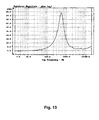
- transducer midrange, treble, bass, harmonic, rank of harmonics, power, power handling, performance, resonance, distortion, dragging, membrane, coloration (modifying the exact sound of a given instrument by giving it , when passing through the transducer, an "acoustic coloration" very slightly different, that the music lover detects), bandwidth, acoustic connection, transparency (ability to make the sound with perfection and no detectable effect of veil), point source, "waterfall (Response curve (in symbolic form of "waterfall”) in frequency in time: the extinction of a given frequency - and of all the frequencies of the band - must be as fast as possible, no "Dragging", and must be ideally instantaneous, that is to say without "extinction accidents” and thus without bringing "color” to a given instrument; Figure 15 etc., etc., as well as HP, “tweeter” and the like are well known to those skilled in the art and will not otherwise be defined here. This is general knowledge of the skilled person.
- the Applicant has managed to design a completely original engine that makes it possible to manufacture a "tweeter” with a very wide band, preferably a Beryllium membrane, which operates in almost infinite load; therefore, its resonant frequency is very low since it is 700 Hz.
- This "tweeter” can operate from 2000 Hz to 40000 Hz with a low rate of distortions.
- the tests were carried out on a FOCAL TM Electra TM 1000 enclosure.
- Be beryllium membrane
- minima 2 kHz as a low frequency point which can be used in practice is a very sensitive point. It impacts the connection between the "tweeter” and the “medium” transducer. If one tries to get down to 2 kHz, there is a problem of power handling of the "tweeter” and against it avoids the medium transducer to become too directive. Indeed, it is necessary to manage the dispersion and acoustic radiation at the connection frequency, that is to say obtain a similar dispersion diagram for the two transducers so that the effect is not noticeable.
- the Applicant then considered increasing the efficiency of the transducer to maintain all the qualities.
- the Applicant has deliberately avoided the use of mechanical resonances which, however, artificially increase the sound level (higher efficiency but artificially, especially using a high resonance frequency and "break up" at 20 kHz not amortized) but which generate a lot of dragging.
- the response curve was initially, during the tests, improved with the removal of the mechanical overvoltage at the beginning of the band and a response curve with few accidents.
- the damping of the beginning of the tape was excellent, but at the expense of the level of distortion.
- the Applicant has therefore continued its research to solve (among other problems) this problem of distortion and further improve the performance of the "tweeter” by increasing the performance.
- the directivity is also very pronounced and the bandwidth in the high spectrum is reduced to 19kHz for the best. Which therefore reserves the sound of high power.
- This system is not suitable for high or very high fidelity high fidelity for which it is essential not to be directive and where it On the contrary, it is necessary to reproduce or recreate the spatial dimension of the stereophonic message.
- the characteristic curves of the ferrocobalt metal for the pole pieces (field plate and core) in the FEMM software or simulation software did not exceed 130,000 (mOe) when it was used until saturation. It was not possible to measure above 130,000 (mOe) because it requires very powerful amplifiers. The inventors were therefore compelled to calculate the values above, up to 240 000 mOe for the program to go to the level of real saturation.
- the invention proposes a completely original engine, and its incorporation in particular a "tweeter” which provides all the benefits referred to in the technical problem specified above, while still achieving some compromises still inevitable to date but in proposing a solution that achieves a "quantum leap" with respect to the prior art.
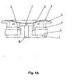
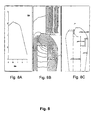
- the present invention covers in particular a motor for a loudspeaker and especially for a "tweeter"("acute” transducer), characterized in that the magnet 6 of the motor is transferred “towards the rear” or “behind the engine” and is adapted as well as the pole pieces (field plate 9 and core 7) to release the volume under the membrane and remove or almost any compression while allowing either a larger volume of magnet or a volume more metal in the polar pieces, or both.
- pole pieces (core 7 and field plate 9) are correspondingly adapted to also form a truncated tube or cone. This will be understood by those skilled in the art since, after “pivoting the magnet,” it is still necessary to generate an effective magnetic field for driving the coil ("radial" magnetization).
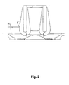
- the assembly thus forms a cylindrical tube, or a truncated cone, possibly with a nozzle effect produced by the pole piece 7 (core) whose inner shape may optionally adopt a venturi profile, cf. figure 1D , Fig. 2 .
- Said inner profile is dictated solely by the amount of metal to be placed in the pole piece 7, this amount being dictated by the distance from the gap. In fact the saturation increases with the proximity of the air gap, and it is therefore advantageous to place more metal when one is near the air gap: an elegant solution is the domed shape or also called "venturi"; a good magnetic optimization is obtained by reducing leaks or magnetic losses while maintaining a more transparent motor.
- this arrangement favors two options that each have advantages, the first being to have more magnet, and the second is to have more metal in the volume released by the new provision.
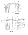
- the decompression vent 8 becomes completely optional according to the invention since the air of the zone ZC can be evacuated freely by the periphery, cf. arrows on the Figure 1C .
- Such a motor characterized in that said magnet is divided into several segments of magnets 6A, 6B, 6C, ... arranged vertically or at an angle relative to the vertical (longitudinal axis of the engine), in particular magnets in position vertically collinear around the core 7, and the field plate 9, leaving an air gap 2 to accommodate the coil 3.
- Such a motor characterized in that said segments form a truncated tube or cone possibly with a "nozzle” or “venturi” effect around the core 7, as can be seen in the accompanying figures, the nozzle effect being explained below. on top to bring more metal to the core and thus move and move the place away from saturation.
- Such a motor characterized in that the polar core and field plate parts and the magnet segments form a "vertical" tube or truncated cone, under the membrane taken as a horizontal reference, cf. anxious figures.
- Such a motor characterized in that the nature of the magnet is neodymium, in particular N38M (Br 12.2 kGs) or optionally N48M (Br 13.6 kGs).
- the thickness of the thinned surface by the decompression remains the same: 1,5m.
- the area thinned by decompression was reduced to a diameter of 64 mm.
- the dimensions of the engine mounting brackets have been increased to 8x12 mm.
- One of the crucial objectives was to improve the performance of the "tweeter” and its performance, to improve the power handling, improve the acoustic quality, the level in the extreme acute.
- the coil thus developed has an inductance of 0.03 mH, an electrical resistance of 6 ohms and a wire diameter of 0.08 mm.
- this reduction in the diameter of the wire may reduce the power handling of the "tweeter” by reducing the copper mass and the fragility of the copper wire (confirmed by the coil manufacturer).
- the use of a Faraday ring has made it possible, among other things, to reduce the inductance of the coil at high frequencies, by the self-induction of an electric current in the Faraday ring that generates a magnetic field that modifies the magnetic field. inductance of the coil.
- the air gap of the engine has not been modified to not lose a magnetic field.
- the level of the "tweeter” is identical to the un-banded motor on the entire band of the "tweeter”.
- the second ring seems to cancel the effect and it has been renounced.
- the inventors thought that the thickness of the ring was too thin to allow a good efficiency of the Faraday ring (intensity of the current in the ring). An increase to a value of the order of 0.2 mm appeared necessary.
- the impedance measurement then made it possible to note a reduction of the resistance at 20 kHz, since it went from 7.7 ohms to 7.2 ohms.
- the effect is also visible on the response curve with an increase of 1 dB from 15 kHz to 30 kHz, and from 2 dB to 40 kHz.
- the inventors then sought a radically different solution.
- the moving element is formed of the coil 3 which oscillates in the "suspended" position in the gap, under the action of the electromagnetic forces, and by the membrane 1 which vibrates under the action of the coil to which the membrane is attached mechanically.
- zone ZC is an airtight volume where inevitably occurs a variable compression very detrimental to performance.
- the prior art often overcomes this problem by a decompression orifice 8 whose effect is weak.
- the magnet used for the prototype of the invention, Figure 1D is neodymium: N38M
- the metal used for the pole pieces is a soft iron: E24 Length of the smallest circuit loop (magnetic field): 10.82 mm Magnet quantity: 6.05 cm3.
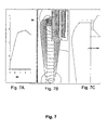
- FIG. 3 which consists of FIGS. 3A to 3C.
- the simulations with FEMM show that we can have a magnetic power increased by 0.2 Tesla (or 2.1 Tesla) compared to the old engine.
- This geometry makes it possible, among other things, to have a looping length that is twice as small as with a conventional motor.
- Figure 4 appended which consists of Figures 4A (7 sectors) and 4B (5 sectors) and is a top view of Figure 1B .
- the average magnetic fields obtained on the prototype motors are 2.05 tesla. This remains a good result since the magnetic field in the gap is greater than the magnetic saturation of the E24.
- the inventors then had to search for the metal of other materials having a higher magnetic saturation than soft iron (1.9 tesla) and found, among other things, ferrocobalt alloys (49% Co in particular) which possess magnetic saturation of 2.4 Teslas.
- a heat treatment at 850 ° C./ for 3 hours makes it possible to increase the permeability by between 1 and 2 teslas relative to an untreated part. This is important because it greatly reduces magnetic leakage and allows it to be concentrated in the air gap.
- the heat treatment very slightly improves the magnetic saturation value. It goes from 2.3 to 2.4 teslas.
- the performance for the more domed core engine was 2.18 teslas for 2.45 simulated.
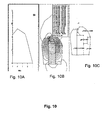
- FIG. 8 which consists of FIGS. 8A to 8C.
- FIG. 9 which consists of FIGS. 9A to 9C.
- the magnetic field in the gap reaches 4.5 Tesla.
- ferrocobalt used is the quality of the ferrocobalt used. Either the metal is polluted by non-permeable compounds (carbon, copper, aluminum, etc.) or ferrocobalt is much less than 49% theoretical of the product used, or a heat treatment has destroyed the magnetic characteristics of ferrocobalt.
- the difference in magnetic field between 2.18 measured and 2.5 simulated is 14%.
- An N48M magnet (Br 13.6 kGs) compared to an N38M magnet (Br 12.2 kGs) provides 11% more magnetic power and could compensate for a part of the missing magnetic field.
- the temperature of the heat treatment affects the performance of the ferrocobalt.
- the maximum performance is obtained at 850 ° C / 3 hours. Above 950 ° C performance begins to fall.
- Measurements on prototype engines using parts treated at 850 ° C and 1100 ° C are however substantially identical.
- the engine using as an external part a soft iron E24 combined with the new arrangement of the engine already offers very good performances since it makes it possible to reach an average field 2, 05 teslas while offering a great decompression.
- the average field measured on the engine of the TGU is 1.95 teslas and on the Focus Ring TM system (Focal patent EP 02 291 719.9 ) of 1.85 teslas.
- This new engine according to the invention can increase the level of the "tweeter" by 1.5 dB compared to the old engine. In addition, it offers a large decompression.
- the new engine obtained allowed to combine high magnetic performances with a large decompression.
- This new engine has an average field of 2.05 Tesla.
- the field increases by 0.2 tesla compared to our previous engine.
- the average field measured on the engine of the TGU is 1.90 teslas and on the Focus Ring TM of 1.85 teslas.
- the "tweeter” (and the new generation engine) according to the invention therefore surprisingly has a higher efficiency despite the absence of mechanical resonance in the useful bandwidth.
- Dynamic capacity and power handling increased by 1.5 dB or 41% more noise level while increasing the quality of reproduction of highs.
- Membrane very preferably in "inverted dome” that is to say as represented on the Figures 1A 1 C 1D .
- Magnets magnetized radially arranged in segments around the core preferably 5 segments, or even better 7 segments, and forming a "vertical” tube or a “rear cone” (as well as polar pieces core and plate field) moved "to the 'rear of the engine', which makes it possible to cleverly clear the compression zone ZC and thus avoid any compression of the air under the membrane; increase in the decompression area, especially to a value around 437 mm 2.
- Loop length of the reduced magnetic circuit including a value of 14.7 mm.
- the invention also covers all the embodiments and all the applications which will be directly accessible to the person skilled in the art upon reading the present application, of his own knowledge, and possibly of simple routine tests.
Landscapes
- Physics & Mathematics (AREA)
- Engineering & Computer Science (AREA)
- Acoustics & Sound (AREA)
- Signal Processing (AREA)
- Health & Medical Sciences (AREA)
- Otolaryngology (AREA)
- Audible-Bandwidth Dynamoelectric Transducers Other Than Pickups (AREA)
Priority Applications (1)
| Application Number | Priority Date | Filing Date | Title |
|---|---|---|---|
| EP08290595A EP2139265A1 (de) | 2008-06-23 | 2008-06-23 | Motor für Tweeter |
Applications Claiming Priority (1)
| Application Number | Priority Date | Filing Date | Title |
|---|---|---|---|
| EP08290595A EP2139265A1 (de) | 2008-06-23 | 2008-06-23 | Motor für Tweeter |
Publications (1)
| Publication Number | Publication Date |
|---|---|
| EP2139265A1 true EP2139265A1 (de) | 2009-12-30 |
Family
ID=40329124
Family Applications (1)
| Application Number | Title | Priority Date | Filing Date |
|---|---|---|---|
| EP08290595A Withdrawn EP2139265A1 (de) | 2008-06-23 | 2008-06-23 | Motor für Tweeter |
Country Status (1)
| Country | Link |
|---|---|
| EP (1) | EP2139265A1 (de) |
Cited By (1)
| Publication number | Priority date | Publication date | Assignee | Title |
|---|---|---|---|---|
| CN110611867A (zh) * | 2019-10-29 | 2019-12-24 | 阮晓强 | 一种自带倒相管功能的扬声器 |
Citations (9)
| Publication number | Priority date | Publication date | Assignee | Title |
|---|---|---|---|---|
| GB703809A (en) * | 1952-01-17 | 1954-02-10 | Tannoy Ltd | Improvements relating to moving coil loudspeakers and other forms of transducer |
| EP0644706A1 (de) * | 1993-09-22 | 1995-03-22 | Sony Corporation | Hornlautsprecher-System |
| US6636612B1 (en) * | 2000-11-03 | 2003-10-21 | Algo Sound, Inc. | Speaker for use in confined spaces |
| EP1381253A1 (de) | 2002-07-09 | 2004-01-14 | FOCAL JMLab | Magnetsystem für einen Lautsprecher mit beweglicher Spule |
| US20040008857A1 (en) * | 2002-07-15 | 2004-01-15 | Marnie Glenn Arthur | Dipole radiating dynamic speaker |
| WO2004034737A1 (en) * | 2002-10-10 | 2004-04-22 | New Transducers Limited | Magnet assembly for loudspeakers |
| FR2854021A1 (fr) * | 2003-04-16 | 2004-10-22 | Focal Jmlab | Transducteur acoustiques en beryllium pur a radiation directe, a membrane de forme concave, pour applications audio notamment pour enceintes acoustiques |
| US6968069B1 (en) * | 2004-01-06 | 2005-11-22 | Stillwater Designs & Audio, Inc. | Low-profile tweeter with lateral air chamber |
| EP1703765A2 (de) * | 2000-12-26 | 2006-09-20 | Anders Sagren | Elektroakustischer Wandler mit demontierbarer Membran und Schwingspuleanordnung |
-
2008
- 2008-06-23 EP EP08290595A patent/EP2139265A1/de not_active Withdrawn
Patent Citations (9)
| Publication number | Priority date | Publication date | Assignee | Title |
|---|---|---|---|---|
| GB703809A (en) * | 1952-01-17 | 1954-02-10 | Tannoy Ltd | Improvements relating to moving coil loudspeakers and other forms of transducer |
| EP0644706A1 (de) * | 1993-09-22 | 1995-03-22 | Sony Corporation | Hornlautsprecher-System |
| US6636612B1 (en) * | 2000-11-03 | 2003-10-21 | Algo Sound, Inc. | Speaker for use in confined spaces |
| EP1703765A2 (de) * | 2000-12-26 | 2006-09-20 | Anders Sagren | Elektroakustischer Wandler mit demontierbarer Membran und Schwingspuleanordnung |
| EP1381253A1 (de) | 2002-07-09 | 2004-01-14 | FOCAL JMLab | Magnetsystem für einen Lautsprecher mit beweglicher Spule |
| US20040008857A1 (en) * | 2002-07-15 | 2004-01-15 | Marnie Glenn Arthur | Dipole radiating dynamic speaker |
| WO2004034737A1 (en) * | 2002-10-10 | 2004-04-22 | New Transducers Limited | Magnet assembly for loudspeakers |
| FR2854021A1 (fr) * | 2003-04-16 | 2004-10-22 | Focal Jmlab | Transducteur acoustiques en beryllium pur a radiation directe, a membrane de forme concave, pour applications audio notamment pour enceintes acoustiques |
| US6968069B1 (en) * | 2004-01-06 | 2005-11-22 | Stillwater Designs & Audio, Inc. | Low-profile tweeter with lateral air chamber |
Cited By (1)
| Publication number | Priority date | Publication date | Assignee | Title |
|---|---|---|---|---|
| CN110611867A (zh) * | 2019-10-29 | 2019-12-24 | 阮晓强 | 一种自带倒相管功能的扬声器 |
Similar Documents
| Publication | Publication Date | Title |
|---|---|---|
| CA2787167C (fr) | Systeme de haut-parleur coaxial a chambre de compression | |
| EP0749265B1 (de) | Hochfrequenzlautsprecher | |
| EP2526705A1 (de) | Elektrodynamische lautsprecherstruktur mit mems-technologie | |
| EP1515584B1 (de) | Lautsprecher und entsprechende Lautsprechergehäuse | |
| EP2177047B1 (de) | Elektrodynamischer wandler, insbesondere nach art eines lautsprechers mit einer ferrofluid-aufhängung und entsprechende vorrichtungen | |
| WO2013068359A1 (fr) | Procede de reduction de vibrations parasites d'un environnement d'un haut-parleur et dispositif de traitement associe | |
| CA2522519C (fr) | Transducteur acoustique en beryllium pur a radiation directe, a membrane de forme concave, pour applications audio notamment pour enceintes acoustiques | |
| CA2947384A1 (fr) | Dispositif de transmission de sons pour ecouteur intra-auriculaire et ecouteur intra-auriculaire | |
| EP2139265A1 (de) | Motor für Tweeter | |
| FR2765767A1 (fr) | Transducteur electroacoustique tres allonge | |
| FR2580886A1 (fr) | Enceinte acoustique multivoie | |
| EP3469812B1 (de) | Elektrodynamischer breitbandwandler für audiokopfhörer und entsprechender audiokopfhörer | |
| EP3063950B1 (de) | Tonsystem mit verbesserter einstellbarer richtwirkung | |
| CA2787162C (fr) | Transducteur electrodynamique a dome et suspension interne | |
| FR3065135A1 (fr) | Enceinte acoustique | |
| WO2021111010A1 (fr) | Haut-parleur à grande excursion, faible distorsion et faible profondeur | |
| FR3104367A1 (fr) | Haut-parleur à grande excursion, faible distorsion et faible profondeur | |
| EP0335892B1 (de) | Verfahren zum korrigieren der amplituden-frequenzcharakteristik einer elektroakustischen wandleranordnung und entsprechende wandlereinrichtung | |
| EP1112670A1 (de) | Harmonischer verstärker und entsprechender elektroakustischer wandler | |
| WO2011086303A1 (fr) | Transducteur électrodynamique comprenant un guide d'onde acoustique assurant une dissipation thermique | |
| WO2021070139A1 (fr) | Dispositif d'absorption acoustique | |
| BE424848A (de) | ||
| EP3596938A1 (de) | Einteilige vorrichtung für eine angetriebene lautsprecherbox | |
| BE407588A (de) |
Legal Events
| Date | Code | Title | Description |
|---|---|---|---|
| PUAI | Public reference made under article 153(3) epc to a published international application that has entered the european phase |
Free format text: ORIGINAL CODE: 0009012 |
|
| AK | Designated contracting states |
Kind code of ref document: A1 Designated state(s): AT BE BG CH CY CZ DE DK EE ES FI FR GB GR HR HU IE IS IT LI LT LU LV MC MT NL NO PL PT RO SE SI SK TR |
|
| AX | Request for extension of the european patent |
Extension state: AL BA MK RS |
|
| 17P | Request for examination filed |
Effective date: 20100319 |
|
| 17Q | First examination report despatched |
Effective date: 20100517 |
|
| AKX | Designation fees paid |
Designated state(s): AT BE BG CH CY CZ DE DK EE ES FI FR GB GR HR HU IE IS IT LI LT LU LV MC MT NL NO PL PT RO SE SI SK TR |
|
| AXX | Extension fees paid |
Extension state: MK Payment date: 20100319 Extension state: BA Payment date: 20100319 Extension state: RS Payment date: 20100319 Extension state: AL Payment date: 20100319 |
|
| STAA | Information on the status of an ep patent application or granted ep patent |
Free format text: STATUS: EXAMINATION IS IN PROGRESS |
|
| STAA | Information on the status of an ep patent application or granted ep patent |
Free format text: STATUS: THE APPLICATION HAS BEEN WITHDRAWN |
|
| 18W | Application withdrawn |
Effective date: 20190207 |