EP2139266A1 - Neuer Signalwandler von tiefen Tönen mit Erregungsmotor für Lautsprecher in Lautsprecherboxen, der eine Anpassung der Kopplung zwischen dem Lautsprecher und dem jeweiligen Raum der Audioausstrahlung erlaubt - Google Patents
Neuer Signalwandler von tiefen Tönen mit Erregungsmotor für Lautsprecher in Lautsprecherboxen, der eine Anpassung der Kopplung zwischen dem Lautsprecher und dem jeweiligen Raum der Audioausstrahlung erlaubt Download PDFInfo
- Publication number
- EP2139266A1 EP2139266A1 EP08290597A EP08290597A EP2139266A1 EP 2139266 A1 EP2139266 A1 EP 2139266A1 EP 08290597 A EP08290597 A EP 08290597A EP 08290597 A EP08290597 A EP 08290597A EP 2139266 A1 EP2139266 A1 EP 2139266A1
- Authority
- EP
- European Patent Office
- Prior art keywords
- power supply
- transducer
- bass
- motor
- excitation
- Prior art date
- Legal status (The legal status is an assumption and is not a legal conclusion. Google has not performed a legal analysis and makes no representation as to the accuracy of the status listed.)
- Ceased
Links
- 230000005284 excitation Effects 0.000 title claims description 28
- 230000008878 coupling Effects 0.000 title claims description 4
- 238000010168 coupling process Methods 0.000 title claims description 4
- 238000005859 coupling reaction Methods 0.000 title claims description 4
- RYGMFSIKBFXOCR-UHFFFAOYSA-N Copper Chemical compound [Cu] RYGMFSIKBFXOCR-UHFFFAOYSA-N 0.000 claims abstract description 5
- 229910052802 copper Inorganic materials 0.000 claims abstract description 4
- 239000010949 copper Substances 0.000 claims abstract description 4
- 230000005291 magnetic effect Effects 0.000 claims description 23
- 230000004044 response Effects 0.000 claims description 8
- 230000008859 change Effects 0.000 claims description 5
- 238000013016 damping Methods 0.000 claims description 3
- 238000005259 measurement Methods 0.000 description 9
- XEEYBQQBJWHFJM-UHFFFAOYSA-N Iron Chemical compound [Fe] XEEYBQQBJWHFJM-UHFFFAOYSA-N 0.000 description 8
- 238000012360 testing method Methods 0.000 description 6
- 230000008033 biological extinction Effects 0.000 description 5
- 230000007547 defect Effects 0.000 description 5
- 238000010438 heat treatment Methods 0.000 description 5
- 238000011160 research Methods 0.000 description 5
- 229910052742 iron Inorganic materials 0.000 description 4
- 238000004519 manufacturing process Methods 0.000 description 4
- 238000013459 approach Methods 0.000 description 3
- 230000033228 biological regulation Effects 0.000 description 3
- 230000000694 effects Effects 0.000 description 3
- 230000004907 flux Effects 0.000 description 3
- 238000012986 modification Methods 0.000 description 3
- 230000004048 modification Effects 0.000 description 3
- 230000005855 radiation Effects 0.000 description 3
- IJGRMHOSHXDMSA-UHFFFAOYSA-N Atomic nitrogen Chemical compound N#N IJGRMHOSHXDMSA-UHFFFAOYSA-N 0.000 description 2
- 238000009529 body temperature measurement Methods 0.000 description 2
- 238000004040 coloring Methods 0.000 description 2
- 238000012937 correction Methods 0.000 description 2
- 238000013461 design Methods 0.000 description 2
- 238000011161 development Methods 0.000 description 2
- 238000005516 engineering process Methods 0.000 description 2
- 238000001914 filtration Methods 0.000 description 2
- 230000006872 improvement Effects 0.000 description 2
- 239000012528 membrane Substances 0.000 description 2
- 230000001105 regulatory effect Effects 0.000 description 2
- 238000004088 simulation Methods 0.000 description 2
- 241001644893 Entandrophragma utile Species 0.000 description 1
- 241000607056 Stenodus leucichthys Species 0.000 description 1
- 240000008042 Zea mays Species 0.000 description 1
- 210000001015 abdomen Anatomy 0.000 description 1
- 230000002745 absorbent Effects 0.000 description 1
- 239000002250 absorbent Substances 0.000 description 1
- 230000001154 acute effect Effects 0.000 description 1
- 230000003466 anti-cipated effect Effects 0.000 description 1
- 230000003416 augmentation Effects 0.000 description 1
- 230000008901 benefit Effects 0.000 description 1
- 230000015572 biosynthetic process Effects 0.000 description 1
- 238000004364 calculation method Methods 0.000 description 1
- 239000003795 chemical substances by application Substances 0.000 description 1
- 230000006835 compression Effects 0.000 description 1
- 238000007906 compression Methods 0.000 description 1
- 239000002826 coolant Substances 0.000 description 1
- 238000001816 cooling Methods 0.000 description 1
- 230000002089 crippling effect Effects 0.000 description 1
- 230000006378 damage Effects 0.000 description 1
- 230000000593 degrading effect Effects 0.000 description 1
- 238000001514 detection method Methods 0.000 description 1
- 239000003302 ferromagnetic material Substances 0.000 description 1
- 239000006260 foam Substances 0.000 description 1
- 230000017525 heat dissipation Effects 0.000 description 1
- 238000009776 industrial production Methods 0.000 description 1
- 239000007788 liquid Substances 0.000 description 1
- 239000000463 material Substances 0.000 description 1
- 239000002184 metal Substances 0.000 description 1
- 229910052751 metal Inorganic materials 0.000 description 1
- 239000003607 modifier Substances 0.000 description 1
- 229910052757 nitrogen Inorganic materials 0.000 description 1
- 238000005457 optimization Methods 0.000 description 1
- 230000008447 perception Effects 0.000 description 1
- 238000012545 processing Methods 0.000 description 1
- 229920006395 saturated elastomer Polymers 0.000 description 1
- 238000003786 synthesis reaction Methods 0.000 description 1
- 230000001052 transient effect Effects 0.000 description 1
- 238000010792 warming Methods 0.000 description 1
Images


Classifications
-
- H—ELECTRICITY
- H04—ELECTRIC COMMUNICATION TECHNIQUE
- H04R—LOUDSPEAKERS, MICROPHONES, GRAMOPHONE PICK-UPS OR LIKE ACOUSTIC ELECTROMECHANICAL TRANSDUCERS; DEAF-AID SETS; PUBLIC ADDRESS SYSTEMS
- H04R9/00—Transducers of moving-coil, moving-strip, or moving-wire type
- H04R9/02—Details
Definitions
- the present invention relates to the technical field of loudspeakers, in particular high and very high-end speakers and in particular their component type bass transducer for loudspeakers speakers.
- the "serious" transducer is a very important element in the design of any acoustic reproduction system.
- the role of the bass is to cover the frequency band in which we find the first harmonics between 20 and 250 Hz.
- the human ear being a "transient type” sensor, it is the perception of all harmonics that will give sound restored all its finesse, its definition, without dragging or "coloring".
- This bass transducer indeed is particularly sensitive to high-level dynamic compression, dragging, and can present very strong colorations if it is poorly studied.
- a loudspeaker can reproduce the entire audible band by the human ear (from 20 to 20 kHz) with a particularly low level of distortion while maintaining high performance.
- the bass was distributed between two speakers, one of very large diameter loaded in a large volume to reproduce the extreme-bass (frequency lower than 70 Hz) and a second speaker smaller for the high-bass (70 Hz to 250 Hz).
- the bass is very sensitive to the listening room, because the sound generated by the bass transducer has wavelengths fairly close to the dimensions of the room. This generates nodes and pressure bellies degrading very seriously the quality of bass.
- FOCAL TM decided to engage more recently a centered approach this time on the possibility of adjusting the level of the transducer. serious to reproduce the frequencies lower than 70 Hz to adapt the speaker to these two external factors which are the room and the amplifier.
- FOCAL TM did not wish to use a globally known solution, that is to say an active electronics (besides with sometimes dubious qualities, much criticized by the audiophiles), but rather of to act in his research with a radically original approach directly at the level of the bass transducer using an excitation motor (that is to say motor employing an electromagnet).
- One of the objectives of the present invention is to achieve the creation of a bass transducer capable of providing a level-adjustable bass level, employing an excitation motor while maintaining a high quality level, and solving the known problems of such an engine, and while achieving extreme simplicity of use.
- the speakers equipped with an active analog filter thus offer the possibility of modifying the level of bass or correcting defects of the speaker. But the signal is then degraded by the passage in a multitude of electronic correction circuits, sources of loss of information and therefore of transparency.
- the power amplifier modules used for each of the transducers are very often of a very average quality.
- the digital active filter reduces the number of circuits traversed by the signal by processing the corrections numerically.
- the accuracy of the calculation comes into play and comes to limit the system with a defined number of decimals.
- the signal is then converted from digital to analog.
- transparency is a well-known concept that resides in the ability of a system to faithfully reproduce a sound without distortion, "coloration” or so-called “veil” effect, the coloring being, because of a reproduction not perfect, a very slight modification of the sound reproduced compared to the sound emitted, which, for an audiophile, gives an instrument a certain "coloration” different from the original.
- the passive filters are positioned between the amplifier and the speaker. They offer adjustment possibilities to lower the level, but do not allow to gain level.
- the Applicant offers on its speakers the possibility of use in "passive biamping". This consists in feeding the bass speaker with a second amplifier. This provides excellent features but requires the customer to purchase another amplifier with among other things the need for a gain adjustment. Filtering is always done by the speaker filter.
- the interest of being able to modify the magnetic power of the transducer to vary the level of bass and also to modify the alignment (form of the frequency response to the high or low cut, here low, and which is related to the overvoltage of the coupled system (or QF quality factor)) was of great importance for the invention.
- the magnetic field can also be more powerful than motors with permanent magnets.
- transducer midrange, treble, bass, bass-bass, harmonic, harmonic range, bass-reflex, boost, power, power handling, performance, resonance, distortion, dragging, membrane, coloration (modifying the the exact sound of a given instrument by giving it, when passing through the transducer, a very slightly different "acoustic coloration", that the music lover detects), bandwidth, acoustic connection, coupling, alignment, transparency (ability to make the sound with perfection and no detectable effect of sail), point source, cutoff, "waterfall” (response curve (in symbolic form of "waterfall”) in frequency in time: the extinction of a given frequency - and all the frequencies of the band - must be as fast as possible, not “dragging", and must be ideally instantaneous, that is to say without "extinction accidents” and thus without bringing "coloration to a given instrument ) and analogs are well known to those skilled in the art and will not be otherwise defined herein. This is general knowledge of the skilled person.
- Another objective to be achieved in the chosen route of research has been to design a motor excitation no longer has the known drawbacks, including intense heating incompatible with a mainstream production.
- the invention relates to both a new bass driver, a new excitation motor and also a new use (or mode of use) of this transducer with a "force factor" BL very much higher (at least doubled in general) compared to what is known to achieve in the prior art, in particular of the order of 25 to 35 , in particular 27 and 34 with a prototype made, against a maximum of 25 in the prior art (this value of 25 only being achieved in the laboratory and at an exorbitant production cost and by achievements that are technically very complex and incompatible with "reasonable" high-end industrial production).
- the Applicant has deliberately avoided the use of mechanical resonances which nevertheless artificially increase the sound level (especially using a high resonance frequency and "break up” (deformation of the membrane and possibly rupture) at 20 kHz not damped) but which generate a lot of dragging (the drag is the frequency response to the extinction of a sound: the extinction of the frequencies concerned should ideally be instantaneous, but we can note “extinction accidents” that is to say frequencies that are slow a little too much to go out; the corresponding frequency / time curve is called “waterfall”).
- the invention manages in this difficult context to achieve a "quantum leap”.
- the Applicant has noted that when the excitation motor is supplied with 60 W continuously inside an enclosure, its temperature can rise very high in temperature, for example 97 ° C.
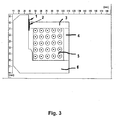
- the thickness of the base plate thus passes according to the invention of 10 mm to 20 mm, and the section of the core passes of 22 mm at 28 mm.
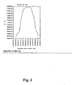
- Magnetic field intensity curve in the air gap of the motor obtained with an excitation power supply power of 90 W.
- the magnetic field reaches 1.75 Tesla and 2.37e-5 Webers
- the UNIQUE APPENDIX table summarizes the results: (temperature, magnetic field, HP performance, competing product).
- the efficiency is much higher than the first version (prior art) of the engine since it required 60 W to obtain the magnetic field of the multiferrite against only 9 W for this new version according to the invention.
- This new motor provides the same magnetic field with 2 times less electrical power applied.
- Temperature resistance problems of the regulator have been measured: 70 - 80 ° C despite large radiators. This represents a significant risk of destruction of electronic components, incompatible with the manufacturer's ten-year warranty.
- Ripples slightly higher than the regulated version have been measured (200 mV) but are acceptable. In addition, they can be further reduced by increasing the filtering capabilities.
- This passive power supply has the advantage of not heating up and withstanding electrical overvoltages.
- the Applicant has deliberately discarded the well-known and advantageous solution of switching power supplies for the following reasons: electrical noise, less reliable power supplies than traditional power supplies.
- An electrical signal detector detects the "presence” of the sound and allows the automatic switching on of the motor supply. It also stops after 15 minutes of inactivity.
Landscapes
- Physics & Mathematics (AREA)
- Engineering & Computer Science (AREA)
- Acoustics & Sound (AREA)
- Signal Processing (AREA)
- Audible-Bandwidth Dynamoelectric Transducers Other Than Pickups (AREA)
Priority Applications (1)
| Application Number | Priority Date | Filing Date | Title |
|---|---|---|---|
| EP08290597A EP2139266A1 (de) | 2008-06-23 | 2008-06-23 | Neuer Signalwandler von tiefen Tönen mit Erregungsmotor für Lautsprecher in Lautsprecherboxen, der eine Anpassung der Kopplung zwischen dem Lautsprecher und dem jeweiligen Raum der Audioausstrahlung erlaubt |
Applications Claiming Priority (1)
| Application Number | Priority Date | Filing Date | Title |
|---|---|---|---|
| EP08290597A EP2139266A1 (de) | 2008-06-23 | 2008-06-23 | Neuer Signalwandler von tiefen Tönen mit Erregungsmotor für Lautsprecher in Lautsprecherboxen, der eine Anpassung der Kopplung zwischen dem Lautsprecher und dem jeweiligen Raum der Audioausstrahlung erlaubt |
Publications (1)
| Publication Number | Publication Date |
|---|---|
| EP2139266A1 true EP2139266A1 (de) | 2009-12-30 |
Family
ID=39808928
Family Applications (1)
| Application Number | Title | Priority Date | Filing Date |
|---|---|---|---|
| EP08290597A Ceased EP2139266A1 (de) | 2008-06-23 | 2008-06-23 | Neuer Signalwandler von tiefen Tönen mit Erregungsmotor für Lautsprecher in Lautsprecherboxen, der eine Anpassung der Kopplung zwischen dem Lautsprecher und dem jeweiligen Raum der Audioausstrahlung erlaubt |
Country Status (1)
| Country | Link |
|---|---|
| EP (1) | EP2139266A1 (de) |
Cited By (1)
| Publication number | Priority date | Publication date | Assignee | Title |
|---|---|---|---|---|
| GB2515098A (en) * | 2013-06-14 | 2014-12-17 | Jaguar Land Rover Ltd | Speaker device |
Citations (4)
| Publication number | Priority date | Publication date | Assignee | Title |
|---|---|---|---|---|
| US1976868A (en) * | 1931-12-18 | 1934-10-16 | Rca Corp | Sound translating device |
| US2295483A (en) * | 1934-06-04 | 1942-09-08 | Jensen Radio Mfg Company | Loudspeaker |
| US4896360A (en) * | 1987-05-27 | 1990-01-23 | Knight Robert S | Public address amplifier |
| US6639994B1 (en) * | 2000-08-16 | 2003-10-28 | Jl Audio, Inc. | Loudspeaker having adjustable motor strength |
-
2008
- 2008-06-23 EP EP08290597A patent/EP2139266A1/de not_active Ceased
Patent Citations (4)
| Publication number | Priority date | Publication date | Assignee | Title |
|---|---|---|---|---|
| US1976868A (en) * | 1931-12-18 | 1934-10-16 | Rca Corp | Sound translating device |
| US2295483A (en) * | 1934-06-04 | 1942-09-08 | Jensen Radio Mfg Company | Loudspeaker |
| US4896360A (en) * | 1987-05-27 | 1990-01-23 | Knight Robert S | Public address amplifier |
| US6639994B1 (en) * | 2000-08-16 | 2003-10-28 | Jl Audio, Inc. | Loudspeaker having adjustable motor strength |
Cited By (3)
| Publication number | Priority date | Publication date | Assignee | Title |
|---|---|---|---|---|
| GB2515098A (en) * | 2013-06-14 | 2014-12-17 | Jaguar Land Rover Ltd | Speaker device |
| GB2515098B (en) * | 2013-06-14 | 2016-02-03 | Jaguar Land Rover Ltd | Speaker device |
| US10009692B2 (en) | 2013-06-14 | 2018-06-26 | Jaguar Land Rover Limited | Speaker device |
Similar Documents
| Publication | Publication Date | Title |
|---|---|---|
| CN103636235B (zh) | 用于扬声器阵列的均衡和/或低音管理的方法和装置 | |
| US7610991B2 (en) | Speaker and method of outputting acoustic sound | |
| US20080226088A1 (en) | Audio Transducer System | |
| US20120063633A1 (en) | Speaker | |
| US20070223734A1 (en) | Speaker | |
| CA2974163C (fr) | Procede d'adaptation du gain de volume pour la limitation de puissance d'un amplificateur et amplificateur | |
| FR2859864A1 (fr) | Haut-parleur et enceinte acoustique correspondante | |
| EP2139266A1 (de) | Neuer Signalwandler von tiefen Tönen mit Erregungsmotor für Lautsprecher in Lautsprecherboxen, der eine Anpassung der Kopplung zwischen dem Lautsprecher und dem jeweiligen Raum der Audioausstrahlung erlaubt | |
| FR3011156A1 (fr) | Equipement de restitution sonore audio haute fidelite | |
| FR2754630A1 (fr) | Procede de fabrication d'un conducteur, ou circuit electrique compense en parasites radioelectriques tels que micro-decharges et conducteur ou circuit correspondant | |
| CA3018544A1 (fr) | Procede de diffusion sonore prenant en compte les particularites individuelles | |
| FR2580886A1 (fr) | Enceinte acoustique multivoie | |
| Allen | The X-Curve: Its Origins and History: Electro-Acoustic Characteristics in the Cinema and the Mix-Room, the Large Room and the Small | |
| US9743201B1 (en) | Loudspeaker array protection management | |
| EP2636227B1 (de) | Mehrkanallautsprecher | |
| JP2010167912A (ja) | 車載用オーディオ装置 | |
| FR3065135A1 (fr) | Enceinte acoustique | |
| CN201267010Y (zh) | 励磁式径向磁路扬声器 | |
| EP0295971A1 (de) | HiFi-elektroakustischer Leistungsumwandler mit versetztem Abstrahlsystem | |
| JP2010093800A (ja) | 重低音出力機能を具備するアコースティック・スピーカー・システム | |
| EP0270394B1 (de) | Verfahren zur Einteilung der akustischen Wiedergabe von modulierten Signalen in parallel geschalteten Umwandlern und Satz von entsprechenden Umwandlern | |
| EP1112670B1 (de) | Harmonischer verstärker und entsprechender elektroakustischer wandler | |
| WO2024095093A1 (fr) | Enceinte acoustique a dispositif de transmission acoustique optimal, et ensemble enceinte acoustique associe | |
| FR2829658A1 (fr) | Dispositif d'amplification et de purification du son | |
| FR2515468A1 (fr) | Ecouteur dynamique |
Legal Events
| Date | Code | Title | Description |
|---|---|---|---|
| PUAI | Public reference made under article 153(3) epc to a published international application that has entered the european phase |
Free format text: ORIGINAL CODE: 0009012 |
|
| AK | Designated contracting states |
Kind code of ref document: A1 Designated state(s): AT BE BG CH CY CZ DE DK EE ES FI FR GB GR HR HU IE IS IT LI LT LU LV MC MT NL NO PL PT RO SE SI SK TR |
|
| AX | Request for extension of the european patent |
Extension state: AL BA MK RS |
|
| 17P | Request for examination filed |
Effective date: 20100324 |
|
| 17Q | First examination report despatched |
Effective date: 20100428 |
|
| AKX | Designation fees paid |
Designated state(s): AT BE BG CH CY CZ DE DK EE ES FI FR GB GR HR HU IE IS IT LI LT LU LV MC MT NL NO PL PT RO SE SI SK TR |
|
| AXX | Extension fees paid |
Extension state: RS Payment date: 20100324 Extension state: MK Payment date: 20100324 Extension state: BA Payment date: 20100324 Extension state: AL Payment date: 20100324 |
|
| STAA | Information on the status of an ep patent application or granted ep patent |
Free format text: STATUS: THE APPLICATION HAS BEEN REFUSED |
|
| 18R | Application refused |
Effective date: 20120308 |