EP2139089B1 - Dreiphasen transformator mit automatischer anpassung der dreiphasen-ausgangsspannung - Google Patents
Dreiphasen transformator mit automatischer anpassung der dreiphasen-ausgangsspannung Download PDFInfo
- Publication number
- EP2139089B1 EP2139089B1 EP08791519A EP08791519A EP2139089B1 EP 2139089 B1 EP2139089 B1 EP 2139089B1 EP 08791519 A EP08791519 A EP 08791519A EP 08791519 A EP08791519 A EP 08791519A EP 2139089 B1 EP2139089 B1 EP 2139089B1
- Authority
- EP
- European Patent Office
- Prior art keywords
- phase
- switch
- winding
- auxiliary winding
- circuit
- Prior art date
- Legal status (The legal status is an assumption and is not a legal conclusion. Google has not performed a legal analysis and makes no representation as to the accuracy of the status listed.)
- Not-in-force
Links
Images


Classifications
-
- H—ELECTRICITY
- H02—GENERATION; CONVERSION OR DISTRIBUTION OF ELECTRIC POWER
- H02J—ELECTRIC POWER NETWORKS; CIRCUIT ARRANGEMENTS OR SYSTEMS FOR SUPPLYING OR DISTRIBUTING ELECTRIC POWER; SYSTEMS FOR STORING ELECTRIC ENERGY
- H02J3/00—Circuit arrangements for AC mains or AC distribution networks
- H02J3/18—Arrangements for adjusting, eliminating or compensating reactive power in networks
- H02J3/1878—Arrangements for adjusting, eliminating or compensating reactive power in networks using tap changing or phase shifting transformers
-
- H—ELECTRICITY
- H02—GENERATION; CONVERSION OR DISTRIBUTION OF ELECTRIC POWER
- H02P—CONTROL OR REGULATION OF ELECTRIC MOTORS, ELECTRIC GENERATORS OR DYNAMO-ELECTRIC CONVERTERS; CONTROLLING TRANSFORMERS, REACTORS OR CHOKE COILS
- H02P13/00—Arrangements for controlling transformers, reactors or choke coils, for the purpose of obtaining a desired output
- H02P13/06—Arrangements for controlling transformers, reactors or choke coils, for the purpose of obtaining a desired output by tap-changing; by rearranging interconnections of windings
-
- H—ELECTRICITY
- H01—ELECTRIC ELEMENTS
- H01F—MAGNETS; INDUCTANCES; TRANSFORMERS; SELECTION OF MATERIALS FOR THEIR MAGNETIC PROPERTIES
- H01F29/00—Variable transformers or inductances not covered by group H01F21/00
- H01F29/02—Variable transformers or inductances not covered by group H01F21/00 with tappings on coil or winding; with provision for rearrangement or interconnection of windings
-
- H—ELECTRICITY
- H01—ELECTRIC ELEMENTS
- H01F—MAGNETS; INDUCTANCES; TRANSFORMERS; SELECTION OF MATERIALS FOR THEIR MAGNETIC PROPERTIES
- H01F30/00—Fixed transformers not covered by group H01F19/00
- H01F30/06—Fixed transformers not covered by group H01F19/00 characterised by the structure
- H01F30/12—Two-phase, three-phase or polyphase transformers
-
- Y—GENERAL TAGGING OF NEW TECHNOLOGICAL DEVELOPMENTS; GENERAL TAGGING OF CROSS-SECTIONAL TECHNOLOGIES SPANNING OVER SEVERAL SECTIONS OF THE IPC; TECHNICAL SUBJECTS COVERED BY FORMER USPC CROSS-REFERENCE ART COLLECTIONS [XRACs] AND DIGESTS
- Y02—TECHNOLOGIES OR APPLICATIONS FOR MITIGATION OR ADAPTATION AGAINST CLIMATE CHANGE
- Y02E—REDUCTION OF GREENHOUSE GAS [GHG] EMISSIONS, RELATED TO ENERGY GENERATION, TRANSMISSION OR DISTRIBUTION
- Y02E40/00—Technologies for an efficient electrical power generation, transmission or distribution
- Y02E40/30—Reactive power compensation
Definitions
- the present invention relates to a transforming apparatus which automatically adjusts the voltage of three-phase power supply led into a power consumer site to within a target voltage range lower than its rated voltage and supplies to load equipment, and particularly to such a transforming apparatus which has a Y-connection three-phase transformer as its basic configuration.
- One of energy saving measures adoptable by general power consumers is a known scheme where the electricity receiving system leading commercial power supply into indoor equipment is provided with the transforming apparatus disclosed in Japanese Patent No. 2750275 or No. 3372178 , which automatically adjusts the voltage of commercial power supply to a voltage several percent lower than its rated voltage and supplies to load equipment.
- the transforming apparatus disclosed in above-cited Japanese Patent No. 3372178 automatically adjusts the voltage of three-phase power supply to within a target voltage range lower than the rated voltage and supplies to load equipment.
- the winding configuration of the transformer used in this transforming apparatus is not in the Y-connection but a special configuration where the current and magnetic flux of each phase are combined with those of the other phases, and hence it is extremely difficult to design its winding circuit and magnetic circuit so as to achieve desired characteristics.
- the above conventional transforming apparatus is configured to change its transformation characteristic by switching on/off a plurality of switches connecting the different phases in combination, and thus the switch needs to be switched on/off at a timing that the voltage between opposite ends of the switch (voltage between different phases) becomes zero.
- a switch control circuit thereof is complicated, and thus it is difficult to secure the stability and reliability of switching operation timings.
- An object of the present invention is to provide a transforming apparatus with a Y-connection three-phase transformer as its basic configuration which automatically adjusts the voltage of three-phase power supply to within a target voltage range lower than the rated voltage and supplies to load equipment.
- a transforming apparatus is characterized by the following items (1) to (22) :
- FIG. 1 shows the winding configuration of a transforming apparatus according to the present invention
- FIG. 3 shows the configuration of a switch switching circuit 8.
- This transforming apparatus comprises three input terminals Rin, Sin, Tin connected respectively to the three main lines of three-phase power supply and three output terminals Rout, Sout, Tout connected to a load installation.
- the transforming apparatus switches between a first mode where the output voltage is made about 2% lower than the input voltage, a second mode where the output voltage is made about 4% lower than the input voltage, a third mode where the output voltage is made about 6% lower than the input voltage, and a fourth mode where the output voltage is substantially equal to the input voltage in an alternative manner.
- the transforming apparatus comprises, as its basic configuration, a Y-connection three-phase transformer made up of an R-phase winding circuit, an S-phase winding circuit, and a T-phase winding circuit, which are the same in configuration, as shown in FIG. 1 .
- an R-phase main winding 10R, an R-phase first auxiliary winding 11R, an R-phase first switch 21R, an R-phase second auxiliary winding 12R, and an R-phase third auxiliary winding 13R are serially connected in that order between the input terminal Rin and a neutral point O.
- the output terminal Rout is connected to the other end of the R-phase main winding 10R.
- An R-phase second switch 22R is connected in parallel with a series circuit of the R-phase first auxiliary winding 11R and the R-phase first switch 21R.
- An R-phase third switch 23R is connected in parallel with a series circuit of the R-phase first auxiliary winding 11R, the R-phase first switch 21R, and the R-phase second auxiliary winding 12R.
- An R-phase fourth switch 24R is connected in parallel with a series circuit of the R-phase second auxiliary winding 12R and the R-phase third auxiliary winding 13R.
- an S-phase main winding 10S, an S-phase first auxiliary winding 11S, an S-phase first switch 21S, an S-phase second auxiliary winding 12S, and an S-phase third auxiliary winding 13S are serially connected in that order between the input terminal Sin and the neutral point O.
- the output terminal Sout is connected to the other end of the S-phase main winding 10S.
- An S-phase second switch 22S is connected in parallel with a series circuit of the S-phase first auxiliary winding 11S and the S-phase first switch 21S.
- An S-phase third switch 23S is connected in parallel with a series circuit of the S-phase first auxiliary winding 11S, the S-phase first switch 21S, and the S-phase second auxiliary winding 12S.
- An S-phase fourth switch 24S is connected in parallel with a series circuit of the S-phase second auxiliary winding 12S and the S-phase third auxiliary winding 13S.
- a T-phase main winding 10T, a T-phase first auxiliary winding 11T, a T-phase first switch 21T, a T-phase second auxiliary winding 12T, and a T-phase third auxiliary winding 13T are serially connected in that order between the input terminal Tin and the neutral point O.
- the output terminal Tout is connected to the other end of the T-phase main winding 10T.
- a T-phase second switch 22T is connected in parallel with a series circuit of the T-phase first auxiliary winding 11T and the T-phase first switch 21T.
- a T-phase third switch 23T is connected in parallel with a series circuit of the T-phase first auxiliary winding 11T, the T-phase first switch 21T, and the T-phase second auxiliary winding 12T.
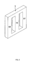
- FIG. 2 shows an example of the form of a core 5 of the Y-connection three-phase transformer.
- the windings 10R, 11R, 12R, 13R of the R-phase winding circuit are wound around an R-phase winding portion 5R of the core 5.
- the windings 10S, 11S, 12S, 13S of the S-phase winding circuit are wound around an S-phase winding portion 5S of the core 5.
- the windings 10T, 11T, 12T, 13T of the T-phase winding circuit are wound around a T-phase winding portion 5T of the core 5.
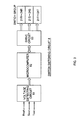
- FIG. 3 shows an example of the configuration of the switch switching circuit 8.
- the switch switching circuit 8 is configured to monitor the voltage levels of the output terminals Rout, Sout, Tout and control a group of the switches of FIG. 1 to switch between the first to fourth modes in an alternative manner such that the output voltage is within a predetermined target voltage range.
- the first switch 21R, 21S, 21T of each phase becomes ON, and all the other switches (the second, third, and fourth switches of each phase) become OFF.
- the output voltage is about 2% lower than the input voltage.
- the second switch 22R, 22S, 22T of each phase becomes ON, and all the other switches (the first, third, and fourth switches of each phase) become OFF.
- the output voltage is about 4% lower than the input voltage.
- the third switch 23R, 23S, 23T of each phase becomes ON, and all the other switches (the first, second, and fourth switches of each phase) become OFF.
- the output voltage is about 6% lower than the input voltage.
- the fourth switch 24R, 24S, 24T of each phase becomes ON, and all the other switches (the first, second, and third switches of each phase) become OFF.
- the output voltage is substantially equal to the input voltage.
- the switch switching circuit 8 comprises a voltage detecting circuit 81, a microcomputer 82, and a drive circuit 83.
- the voltage detecting circuit 81 detects the voltage levels of the output terminals Rout, Sout, Tout and inputs a detection signal to the microcomputer 82.
- the microcomputer 82 inputs control signals to the drive circuit 83 to switch between the first to fourth modes in an alternative manner.
- the drive circuit 83 switches on/off the first to fourth switches 21R to 24R of the R-phase, the first to fourth switches 21S to 24S of the S-phase, and the first to fourth switches 21T to 24T of the T-phase as described above.
- the microcomputer 82 compares the programmed target voltage range and the detection signal from the voltage detecting circuit 81, thereby monitoring whether the output voltage is higher or lower than the target voltage range (steps 410 and 420).
- the process proceeds to a voltage lowering routine of step 411 and later.
- the transformer when currently in the fourth mode (0% mode), the transformer is made to switch to the first mode (-2% mode); when currently in the first mode (-2% mode), to switch to the second mode (-4% mode); and when currently in the second mode (-4% mode), to switch to the third mode (-6% mode).
- step 421 If the output voltage is lower than the target voltage range, the process proceeds to a voltage raising routine of step 421 and later.
- the transformer when currently in the third mode (-6% mode), the transformer is made to switch to the second mode (-4% mode); when currently in the second mode (-4% mode), to switch to the first mode (-2% mode); and when currently in the first mode (-2% mode), to switch to the fourth mode (0% mode).
- the twelve switches are included in the circuit of the Y-connection three-phase transformer shown in FIG. 1 , and these switches are individually switched on/off by the drive circuit 83 shown in FIG. 3 .
- the twelve switches and their respective circuits in the drive circuit 83 are the same in configuration as one another.
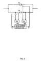
- FIG. 5 shows an example configuration of one of the twelve switches and its one corresponding circuit in the drive circuit 83.
- the switch consists of two thyristors 51, 52 connected in parallel in an opposite direction to each other.
- the drive circuit 83 comprises a gate signal generating circuit 53 and two voltage detecting circuits 54, 55.
- the gate signal generating circuit 53 outputs a gate signal G1 to turn on the thyristor 51 and a gate signal G2 to turn on the thyristor 52.
- the voltage detecting circuit 54 detects the gate-to-cathode voltage of the thyristor 51, and its output signal A becomes "1" when the gate-to-cathode voltage becomes zero (the current through the thyristor 51 becomes zero) and is at "0" when a current flows through the thyristor 51 with the gate-to-cathode voltage being not zero.
- the voltage detecting circuit 55 detects the gate-to-cathode voltage of the thyristor 52, and its output signal B becomes "1" when the gate-to-cathode voltage becomes zero (the current through the thyristor 52 becomes zero) and is at "0" when a current flows through the thyristor 5 with the gate-to-cathode voltage being not zero.
- the gate signal generating circuit 53 turns off the thyristors 51, 52 through the gate signals thereof in response to the output signals A, B of the voltage detecting circuits 54, 55 changing to "1". Further, another switch (two thyristors connected in parallel in an opposite direction to each other) to be turned on instead of the thyristors 51, 52 (one switch) turned off is turned on.
- the switch switching circuit 8 of FIG. 3 is configured to switch on/off the switches of each phase at a timing that the voltage instantaneous value of the phase becomes zero to switch the modes.
- each switch consists of thyristors connected in parallel in an opposite direction to each other, and the switch switching circuit 8 comprises the voltage detector detecting the gate-to-cathode voltage of each thyristor and is configured to turn off a thyristor with turning on another thyristor in response to a timing that its gate-to-cathode voltage is detected to have just become zero via the voltage detector of the thyristor to be turned off.
Landscapes
- Engineering & Computer Science (AREA)
- Power Engineering (AREA)
- Control Of Electrical Variables (AREA)
- Ac-Ac Conversion (AREA)
- Supply And Distribution Of Alternating Current (AREA)
Claims (2)
- Transformatorvorrichtung zum automatischen Anpassen einer Spannung eines Dreiphasennetzgerätes, aufweisend
drei Eingänge (Rin, Sin, Tin),
drei Ausgänge (Rout, Sout, Tout),
einen Y-förmig verbundenen Dreiphasentransformator und eine Anordnung von Schaltern (21 R-24R, 21S-24S, 21 T-24T),
dadurch gekennzeichnet, dass die Transformatorvorrichtung einen Schalterschaltungsschaltkreis (8) umfasst, wobei
die drei Eingänge (Rin, Sin, Tin) mit jeweils einer Phase des Dreiphasennetzgerätes verbunden sind,
die drei Ausgänge (Rout, Sout, Tout) mit einer Verbraucheranlage verbunden sind,
der Y-förmig verbundene Dreiphasentransformator einen Kern (5), einen R-Phasenwicklungsstromkreis, einen S-Phasenwicklungsstromkreis und einen T-Phasenwicklungsstromkreis aufweist,
in dem R-Phasenwicklungsstromkreis eine R-Phasenhauptwicklung (10R), eine erste R-Phasenhilfswicklung (11R), ein erster R-Phasenschalter (21 R), eine zweite R-Phasenhilfswicklung (12R) und eine dritte R-Phasenhilfswicklung (13R) in dieser Abfolge zwischen dem Eingang (Rin) und einem Sternpunkt 0 in Reihe verbunden sind und der Ausgang (Rout) mit dem anderen Ende der R-Phasenhauptwicklung (10R) verbunden ist,
ein zweiter R-Phasenschalter (22R) der Anordnung von Schaltern mit einer Reihenschaltung der ersten R-Phasenhilfswicklung (11R) und dem ersten R-Phasenschalter (21 R) parallel verbunden ist,
ein dritter R-Phasenschalter (23R) der Anordnung von Schaltern mit einer Reihenschaltung der ersten R-Phasenhilfswicklung (11R), dem ersten R-Phasenschalter (21 R) und der zweiten R-Phasenhilfswicklung (12R) parallel verbunden ist,
ein vierter R-Phasenschalter (24R) der Anordnung von Schaltern mit einer Reihenschaltung der zweiten R-Phasenhilfswicklung (12R) und der dritten R-Phasenhilfswicklung (13R) parallel verbunden ist,
in dem S-Phasenwicklungsstromkreis eine S-Phasenhauptwicklung (10S), eine erste S-Phasenhilfswicklung (11S), ein erster S-Phasenschalter (21 S), eine zweite S-Phasenhilfswicklung (12S) und eine dritte S-Phasenhilfswicklung (13S) in dieser Abfolge zwischen dem Eingang (Sin) und dem Sternpunkt 0 in Reihe verbunden sind und der Ausgang (Sout) mit dem anderen Ende der S-Phasenhauptwicklung (10S) verbunden ist,
ein zweiter S-Phasenschalter (22S) der Anordnung von Schaltern mit einer Reihenschaltung der ersten S-Phasenhilfswicklung (11S) und dem ersten S-Phasenschalter (21 S) parallel verbunden ist,
ein dritter S-Phasenschalter (23S) der Anordnung von Schaltern mit einer Reihenschaltung der ersten S-Phasenhilfswicklung (11S), dem ersten S-Phasenschalter (21S) und der zweiten S-Phasenhilfswicklung (12S) parallel verbunden ist,
ein vierter S-Phasenschalter (24S) der Anordnung von Schaltern mit einer Reihenschaltung der zweiten S-Phasenhilfswicklung (12S) und der dritten S-Phasenhilfswicklung (13S) parallel verbunden ist,
in dem T-Phasenwicklungsstromkreis eine T-Phasenhauptwicklung (10T), eine erste T-Phasenhilfswicklung (11T), ein erster T-Phasenschalter (21T), eine zweite T-Phasenhilfswicklung (12T) und eine dritte T-Phasenhilfswicklung (13T) in dieser Abfolge zwischen dem Eingang (Tin) und dem Sternpunkt 0 in Reihe verbunden sind und der Ausgang (Tout) mit dem anderen Ende der T-Phasenhauptwicklung (10T) verbunden ist,
ein zweiter T-Phasenschalter (22T) der Anordnung von Schaltern mit einer Reihenschaltung der ersten T-Phasenhilfswicklung (11T) und dem ersten T-Phasenschalter (21T) parallel verbunden ist,
ein dritter T-Phasenschalter (23T) der Anordnung von Schaltern mit einer Reihenschaltung der ersten T-Phasenhilfswicklung (11T), dem ersten T-Phasenschalter (21T) und der zweiten T-Phasenhilfswicklung (12T) parallel verbunden ist,
ein vierter T-Phasenschalter (24T) der Anordnung von Schaltern mit einer Reihenschaltung der zweiten T-Phasenhilfswicklung (12T) und der dritten T-Phasenhilfswicklung (13T) parallel verbunden ist,
der Schalterschaltungsschaltkreis (8) auf Grund von Spannungsniveaus der Ausgänge (Rout, Sout, Tout) oder der Eingänge (Rin, Sin, Tin) zum Kontrollieren der Schalter ausgestaltet ist, um in einer sich gegenseitig ausschließenden Weise in einen ersten, zweiten, dritten oder vierten Modus zu schalten, so dass
in dem ersten Modus die ersten Schalter (21 R, 21S, 21T) einer jeden Phase eingeschalten sind und die zweiten (22R, 22S, 22T), dritten (23R, 23S, 23T) und vierten (24R, 24S, 24T) Schalter einer jeden Phase ausgeschalten sind,
in dem zweiten Modus die zweiten Schalter (22R, 22S, 22T) einer jeden Phase eingeschalten sind und die ersten (21 R, 21S, 21T), dritten (23R, 23S, 23T) und vierten (24R, 24S, 24T) Schalter einer jeden Phase ausgeschalten sind,
in dem dritten Modus die dritten Schalter (23R, 23S, 23T) einer jeden Phase eingeschalten sind und die ersten (21R, 21S, 21T), zweiten (22R, 22S, 22T) und vierten (24R, 24S, 24T) Schalter einer jeden Phase ausgeschalten sind,
in dem vierten Modus die vierten Schalter (24R, 24S, 24T) einer jeden Phase eingeschalten sind und die ersten (21 R, 21S, 21T), zweiten (22R, 22S, 22T) und dritten (23R, 23S, 23T) Schalter einer jeden Phase ausgeschalten sind, und
der Schalterschaltungsschaltkreis (8) zum Ein- und Ausschalten der Schalter einer jeden Phase bei einem Nulldurchgang der momentan an der Phase anliegenden Spannung ausgestaltet ist, um die Moden zu schalten. - Transformatorvorrichtung nach Anspruch 1, wobei ein jeder der Schalter (21R-24R, 21S-24S, 21T-24T) parallel und zueinander entgegengesetzt wirkend verbundene Thyristoren (51, 52) umfasst, und der Schalterschaltungsschaltkreis (8) Spannungsmesser (54, 55) zum Messen der Tor-Kathoden-Spannung für jeden der Thyristoren aufweist und einen Thyristor abschaltend ist auf Grund eines Anschaltens des anderen Thyristors als Reaktion auf den Nulldurchgang seiner durch den Spannungsmesser des abzuschaltenden Thyristors gemessenen Tor-Kathoden-Spannung.
Applications Claiming Priority (1)
| Application Number | Priority Date | Filing Date | Title |
|---|---|---|---|
| PCT/JP2008/063267 WO2009136451A1 (ja) | 2008-07-24 | 2008-07-24 | 三相電源の電圧を自動調整する変圧装置 |
Publications (4)
| Publication Number | Publication Date |
|---|---|
| EP2139089A1 EP2139089A1 (de) | 2009-12-30 |
| EP2139089A4 EP2139089A4 (de) | 2010-06-16 |
| EP2139089B1 true EP2139089B1 (de) | 2011-07-20 |
| EP2139089B8 EP2139089B8 (de) | 2011-10-05 |
Family
ID=41036711
Family Applications (1)
| Application Number | Title | Priority Date | Filing Date |
|---|---|---|---|
| EP08791519A Not-in-force EP2139089B8 (de) | 2008-07-24 | 2008-07-24 | Dreiphasen transformator mit automatischer anpassung der dreiphasen-ausgangsspannung |
Country Status (12)
| Country | Link |
|---|---|
| US (1) | US7786717B2 (de) |
| EP (1) | EP2139089B8 (de) |
| JP (1) | JP4312826B1 (de) |
| CN (1) | CN101689759B (de) |
| AR (1) | AR069069A1 (de) |
| AT (1) | ATE517456T1 (de) |
| BR (1) | BRPI0804505A2 (de) |
| CA (1) | CA2646173C (de) |
| ES (1) | ES2395064T3 (de) |
| MX (1) | MX2008016544A (de) |
| TW (1) | TWI320985B (de) |
| WO (1) | WO2009136451A1 (de) |
Cited By (1)
| Publication number | Priority date | Publication date | Assignee | Title |
|---|---|---|---|---|
| DE102016218439A1 (de) | 2016-09-26 | 2018-03-29 | Bayerische Motoren Werke Aktiengesellschaft | Aufbau eines lokalen dreiphasigen Stromnetzes |
Families Citing this family (7)
| Publication number | Priority date | Publication date | Assignee | Title |
|---|---|---|---|---|
| WO2012126860A2 (en) | 2011-03-18 | 2012-09-27 | Powerperfector Limited | A controller for a transformer |
| US20150247886A1 (en) * | 2014-02-28 | 2015-09-03 | International Business Machines Corporation | Transformer Phase Permutation Causing More Uniform Transformer Phase Aging and general switching network suitable for same |
| CN108282042A (zh) * | 2018-01-19 | 2018-07-13 | 华中科技大学 | 一种基于变绕组匝数的调速永磁同步电机 |
| CN111478642B (zh) * | 2020-04-16 | 2022-03-01 | 广州华凌制冷设备有限公司 | 驱动控制电路、驱动控制方法、线路板及空调器 |
| WO2022125255A1 (en) * | 2020-12-07 | 2022-06-16 | S&C Electric Company | Phase balancing and lv mesh switching |
| CN114069607B (zh) * | 2021-10-08 | 2024-05-14 | 井上和一 | 智能电压控制方法和控制系统 |
| CA3236145A1 (en) | 2021-10-22 | 2023-04-27 | Southwest Electric Co. | Three-phase multi-tap balancing distribution transformer |
Family Cites Families (8)
| Publication number | Priority date | Publication date | Assignee | Title |
|---|---|---|---|---|
| JPH0645320A (ja) | 1992-07-27 | 1994-02-18 | Nec Corp | 半導体装置の製造方法および製造装置 |
| JPH0645320U (ja) | 1992-11-24 | 1994-06-14 | 株式会社明電舎 | 変圧器内蔵式電圧調整装置 |
| JP2996377B2 (ja) * | 1993-07-10 | 1999-12-27 | 永田 勝彦 | 交流入力電圧に応じて単巻変圧器の降圧比を制御する装置 |
| JP2750275B2 (ja) * | 1995-01-10 | 1998-05-13 | 愛好電機株式会社 | 昇降同圧自律切替装置付き省電力変圧器 |
| AU6015196A (en) | 1995-06-12 | 1997-02-05 | Nariisa Imoto | Voltage regulator |
| JPH09247857A (ja) | 1996-01-05 | 1997-09-19 | Kawamura Electric Inc | 節電装置 |
| JP3372178B2 (ja) | 1996-12-25 | 2003-01-27 | 愛好電機株式会社 | 3相式電圧自動切替装置付き省電力装置 |
| JP2000125473A (ja) | 1998-10-19 | 2000-04-28 | Toshiba Corp | 電力調整装置及びその装置の制御方法 |
-
2008
- 2008-07-24 AT AT08791519T patent/ATE517456T1/de not_active IP Right Cessation
- 2008-07-24 EP EP08791519A patent/EP2139089B8/de not_active Not-in-force
- 2008-07-24 JP JP2008554355A patent/JP4312826B1/ja not_active Expired - Fee Related
- 2008-07-24 CN CN2008800002921A patent/CN101689759B/zh not_active Expired - Fee Related
- 2008-07-24 US US12/377,920 patent/US7786717B2/en not_active Expired - Fee Related
- 2008-07-24 WO PCT/JP2008/063267 patent/WO2009136451A1/ja not_active Ceased
- 2008-07-24 CA CA2646173A patent/CA2646173C/en not_active Expired - Fee Related
- 2008-07-24 MX MX2008016544A patent/MX2008016544A/es active IP Right Grant
- 2008-07-24 ES ES08791519T patent/ES2395064T3/es active Active
- 2008-07-24 BR BRPI0804505-4A patent/BRPI0804505A2/pt not_active IP Right Cessation
- 2008-12-03 TW TW097146982A patent/TWI320985B/zh not_active IP Right Cessation
- 2008-12-09 AR ARP080105325A patent/AR069069A1/es active IP Right Grant
Cited By (1)
| Publication number | Priority date | Publication date | Assignee | Title |
|---|---|---|---|---|
| DE102016218439A1 (de) | 2016-09-26 | 2018-03-29 | Bayerische Motoren Werke Aktiengesellschaft | Aufbau eines lokalen dreiphasigen Stromnetzes |
Also Published As
| Publication number | Publication date |
|---|---|
| BRPI0804505A2 (pt) | 2011-08-30 |
| ATE517456T1 (de) | 2011-08-15 |
| CA2646173C (en) | 2011-08-02 |
| WO2009136451A1 (ja) | 2009-11-12 |
| CN101689759A (zh) | 2010-03-31 |
| TWI320985B (en) | 2010-02-21 |
| US7786717B2 (en) | 2010-08-31 |
| TW201006088A (en) | 2010-02-01 |
| JPWO2009136451A1 (ja) | 2011-09-01 |
| CN101689759B (zh) | 2012-11-28 |
| US20100164444A1 (en) | 2010-07-01 |
| EP2139089A1 (de) | 2009-12-30 |
| EP2139089B8 (de) | 2011-10-05 |
| ES2395064T3 (es) | 2013-02-07 |
| CA2646173A1 (en) | 2009-10-23 |
| EP2139089A4 (de) | 2010-06-16 |
| HK1139517A1 (en) | 2010-09-17 |
| AR069069A1 (es) | 2009-12-30 |
| JP4312826B1 (ja) | 2009-08-12 |
| MX2008016544A (es) | 2010-02-17 |
Similar Documents
| Publication | Publication Date | Title |
|---|---|---|
| EP2139089B1 (de) | Dreiphasen transformator mit automatischer anpassung der dreiphasen-ausgangsspannung | |
| GB2580748A (en) | Controlling voltage in AC power lines | |
| WO1998029788A1 (fr) | Procede et dispositif de commutation automatique de tension triphasee pour transformateur economiseur d'energie | |
| JP5731143B2 (ja) | 電圧調整装置 | |
| EP2044684B1 (de) | Variable spannungsversorgungssystem | |
| AU2008255124B2 (en) | Transforming apparatus for automatically adjusting three-phase power supply voltage | |
| WO2008044374A1 (fr) | Procédé pour détecter la mise hors fonction de thyristor | |
| HK1139517B (en) | Transformation device for automatically adjusting voltage of three-phase power supply | |
| KR100519380B1 (ko) | 3상 무순단 탭전환 변압기 시스템 | |
| CN115742887B (zh) | 铁路贯通同相供电改造的多源互联牵引供电系统和方法 | |
| KR200392618Y1 (ko) | 탭 절환방식을 이용한 가포화 리액터식 절전장치 | |
| KR20100011876A (ko) | 3상 전원 전압을 자동으로 조정하는 변압 장치 | |
| KR20160080719A (ko) | 한시적으로 동작하는 전력 시스템과 연결되도록 구성된 전력 제어 장치 및 전력 제어 방법 | |
| WO2021000610A1 (zh) | 电压平衡稳定装置及方法 | |
| US20240372481A1 (en) | Method and system for operating a control transformer | |
| CN211859614U (zh) | 一种三相不平衡电源发生器 | |
| JPH0746763A (ja) | 無効電力調整装置 | |
| KR100709621B1 (ko) | 전압조절기능을 가진 가포화 리액터식 전력제어장치를내장한 가로등 분전함 | |
| KR200410123Y1 (ko) | 전압조절기능을 가진 가포화 리액터식 전력제어장치를내장한 가로등 분전함 | |
| JP2000148267A (ja) | 交流電源装置 | |
| KR20230108590A (ko) | 지상 무효 전력 공급 장치 및 이의 온도 보정을 제어하기 위한 방법 | |
| CN205305210U (zh) | 照明稳压节能柜 | |
| KR20060118930A (ko) | 위상비교제어를 이용한 리니어 교류 전력제어장치 | |
| JPH0767339A (ja) | 制御整流器一次側交流線路の力率改善方法 | |
| HK1129499A1 (en) | Variable voltage supply system |
Legal Events
| Date | Code | Title | Description |
|---|---|---|---|
| PUAI | Public reference made under article 153(3) epc to a published international application that has entered the european phase |
Free format text: ORIGINAL CODE: 0009012 |
|
| 17P | Request for examination filed |
Effective date: 20090316 |
|
| AK | Designated contracting states |
Kind code of ref document: A1 Designated state(s): AT BE BG CH CY CZ DE DK EE ES FI FR GB GR HR HU IE IS IT LI LT LU LV MC MT NL NO PL PT RO SE SI SK TR |
|
| A4 | Supplementary search report drawn up and despatched |
Effective date: 20100520 |
|
| RIC1 | Information provided on ipc code assigned before grant |
Ipc: H02J 3/18 20060101AFI20100512BHEP Ipc: H01F 29/02 20060101ALN20100512BHEP |
|
| REG | Reference to a national code |
Ref country code: HK Ref legal event code: DE Ref document number: 1139517 Country of ref document: HK |
|
| GRAP | Despatch of communication of intention to grant a patent |
Free format text: ORIGINAL CODE: EPIDOSNIGR1 |
|
| RIC1 | Information provided on ipc code assigned before grant |
Ipc: H01F 29/02 20060101ALN20101105BHEP Ipc: H02J 3/18 20060101AFI20101105BHEP |
|
| DAX | Request for extension of the european patent (deleted) | ||
| GRAS | Grant fee paid |
Free format text: ORIGINAL CODE: EPIDOSNIGR3 |
|
| RIN1 | Information on inventor provided before grant (corrected) |
Inventor name: TSUNEMI, SEIJI Inventor name: SHIMAZU, CHIYUKI |
|
| GRAA | (expected) grant |
Free format text: ORIGINAL CODE: 0009210 |
|
| AK | Designated contracting states |
Kind code of ref document: B1 Designated state(s): AT BE BG CH CY CZ DE DK EE ES FI FR GB GR HR HU IE IS IT LI LT LU LV MC MT NL NO PL PT RO SE SI SK TR |
|
| REG | Reference to a national code |
Ref country code: GB Ref legal event code: FG4D |
|
| REG | Reference to a national code |
Ref country code: CH Ref legal event code: EP |
|
| RAP2 | Party data changed (patent owner data changed or rights of a patent transferred) |
Owner name: POWERPERFECTOR LIMITED |
|
| REG | Reference to a national code |
Ref country code: DE Ref legal event code: R096 Ref document number: 602008008405 Country of ref document: DE Effective date: 20110908 |
|
| REG | Reference to a national code |
Ref country code: NL Ref legal event code: VDEP Effective date: 20110720 |
|
| PG25 | Lapsed in a contracting state [announced via postgrant information from national office to epo] |
Ref country code: MT Free format text: LAPSE BECAUSE OF FAILURE TO SUBMIT A TRANSLATION OF THE DESCRIPTION OR TO PAY THE FEE WITHIN THE PRESCRIBED TIME-LIMIT Effective date: 20110720 |
|
| REG | Reference to a national code |
Ref country code: AT Ref legal event code: MK05 Ref document number: 517456 Country of ref document: AT Kind code of ref document: T Effective date: 20110720 |
|
| PG25 | Lapsed in a contracting state [announced via postgrant information from national office to epo] |
Ref country code: FI Free format text: LAPSE BECAUSE OF FAILURE TO SUBMIT A TRANSLATION OF THE DESCRIPTION OR TO PAY THE FEE WITHIN THE PRESCRIBED TIME-LIMIT Effective date: 20110720 Ref country code: BE Free format text: LAPSE BECAUSE OF FAILURE TO SUBMIT A TRANSLATION OF THE DESCRIPTION OR TO PAY THE FEE WITHIN THE PRESCRIBED TIME-LIMIT Effective date: 20110720 Ref country code: HR Free format text: LAPSE BECAUSE OF FAILURE TO SUBMIT A TRANSLATION OF THE DESCRIPTION OR TO PAY THE FEE WITHIN THE PRESCRIBED TIME-LIMIT Effective date: 20110720 Ref country code: NO Free format text: LAPSE BECAUSE OF FAILURE TO SUBMIT A TRANSLATION OF THE DESCRIPTION OR TO PAY THE FEE WITHIN THE PRESCRIBED TIME-LIMIT Effective date: 20111020 Ref country code: SE Free format text: LAPSE BECAUSE OF FAILURE TO SUBMIT A TRANSLATION OF THE DESCRIPTION OR TO PAY THE FEE WITHIN THE PRESCRIBED TIME-LIMIT Effective date: 20110720 Ref country code: PT Free format text: LAPSE BECAUSE OF FAILURE TO SUBMIT A TRANSLATION OF THE DESCRIPTION OR TO PAY THE FEE WITHIN THE PRESCRIBED TIME-LIMIT Effective date: 20111121 Ref country code: NL Free format text: LAPSE BECAUSE OF FAILURE TO SUBMIT A TRANSLATION OF THE DESCRIPTION OR TO PAY THE FEE WITHIN THE PRESCRIBED TIME-LIMIT Effective date: 20110720 Ref country code: IS Free format text: LAPSE BECAUSE OF FAILURE TO SUBMIT A TRANSLATION OF THE DESCRIPTION OR TO PAY THE FEE WITHIN THE PRESCRIBED TIME-LIMIT Effective date: 20111120 Ref country code: LT Free format text: LAPSE BECAUSE OF FAILURE TO SUBMIT A TRANSLATION OF THE DESCRIPTION OR TO PAY THE FEE WITHIN THE PRESCRIBED TIME-LIMIT Effective date: 20110720 |
|
| PG25 | Lapsed in a contracting state [announced via postgrant information from national office to epo] |
Ref country code: SI Free format text: LAPSE BECAUSE OF FAILURE TO SUBMIT A TRANSLATION OF THE DESCRIPTION OR TO PAY THE FEE WITHIN THE PRESCRIBED TIME-LIMIT Effective date: 20110720 Ref country code: CY Free format text: LAPSE BECAUSE OF FAILURE TO SUBMIT A TRANSLATION OF THE DESCRIPTION OR TO PAY THE FEE WITHIN THE PRESCRIBED TIME-LIMIT Effective date: 20110720 Ref country code: MC Free format text: LAPSE BECAUSE OF NON-PAYMENT OF DUE FEES Effective date: 20110731 Ref country code: PL Free format text: LAPSE BECAUSE OF FAILURE TO SUBMIT A TRANSLATION OF THE DESCRIPTION OR TO PAY THE FEE WITHIN THE PRESCRIBED TIME-LIMIT Effective date: 20110720 Ref country code: LV Free format text: LAPSE BECAUSE OF FAILURE TO SUBMIT A TRANSLATION OF THE DESCRIPTION OR TO PAY THE FEE WITHIN THE PRESCRIBED TIME-LIMIT Effective date: 20110720 Ref country code: AT Free format text: LAPSE BECAUSE OF FAILURE TO SUBMIT A TRANSLATION OF THE DESCRIPTION OR TO PAY THE FEE WITHIN THE PRESCRIBED TIME-LIMIT Effective date: 20110720 Ref country code: GR Free format text: LAPSE BECAUSE OF FAILURE TO SUBMIT A TRANSLATION OF THE DESCRIPTION OR TO PAY THE FEE WITHIN THE PRESCRIBED TIME-LIMIT Effective date: 20111021 |
|
| REG | Reference to a national code |
Ref country code: DE Ref legal event code: R081 Ref document number: 602008008405 Country of ref document: DE Owner name: POWERPERFECTOR LIMITED, GB Free format text: FORMER OWNER: E-FOUR CORPORATION, SAITAMA, JP Effective date: 20120105 Ref country code: DE Ref legal event code: R081 Ref document number: 602008008405 Country of ref document: DE Owner name: INTELLIGENT ENERGY SAVING COMPANY LIMITED, GB Free format text: FORMER OWNER: E-FOUR CORPORATION, SAITAMA, JP Effective date: 20120105 |
|
| REG | Reference to a national code |
Ref country code: IE Ref legal event code: MM4A |
|
| PG25 | Lapsed in a contracting state [announced via postgrant information from national office to epo] |
Ref country code: CZ Free format text: LAPSE BECAUSE OF FAILURE TO SUBMIT A TRANSLATION OF THE DESCRIPTION OR TO PAY THE FEE WITHIN THE PRESCRIBED TIME-LIMIT Effective date: 20110720 Ref country code: SK Free format text: LAPSE BECAUSE OF FAILURE TO SUBMIT A TRANSLATION OF THE DESCRIPTION OR TO PAY THE FEE WITHIN THE PRESCRIBED TIME-LIMIT Effective date: 20110720 |
|
| REG | Reference to a national code |
Ref country code: HK Ref legal event code: GR Ref document number: 1139517 Country of ref document: HK |
|
| PLBE | No opposition filed within time limit |
Free format text: ORIGINAL CODE: 0009261 |
|
| STAA | Information on the status of an ep patent application or granted ep patent |
Free format text: STATUS: NO OPPOSITION FILED WITHIN TIME LIMIT |
|
| PG25 | Lapsed in a contracting state [announced via postgrant information from national office to epo] |
Ref country code: RO Free format text: LAPSE BECAUSE OF FAILURE TO SUBMIT A TRANSLATION OF THE DESCRIPTION OR TO PAY THE FEE WITHIN THE PRESCRIBED TIME-LIMIT Effective date: 20110720 Ref country code: EE Free format text: LAPSE BECAUSE OF FAILURE TO SUBMIT A TRANSLATION OF THE DESCRIPTION OR TO PAY THE FEE WITHIN THE PRESCRIBED TIME-LIMIT Effective date: 20110720 |
|
| 26N | No opposition filed |
Effective date: 20120423 |
|
| PG25 | Lapsed in a contracting state [announced via postgrant information from national office to epo] |
Ref country code: DK Free format text: LAPSE BECAUSE OF FAILURE TO SUBMIT A TRANSLATION OF THE DESCRIPTION OR TO PAY THE FEE WITHIN THE PRESCRIBED TIME-LIMIT Effective date: 20110720 |
|
| REG | Reference to a national code |
Ref country code: FR Ref legal event code: ST Effective date: 20120525 |
|
| PG25 | Lapsed in a contracting state [announced via postgrant information from national office to epo] |
Ref country code: IE Free format text: LAPSE BECAUSE OF NON-PAYMENT OF DUE FEES Effective date: 20110724 |
|
| REG | Reference to a national code |
Ref country code: DE Ref legal event code: R097 Ref document number: 602008008405 Country of ref document: DE Effective date: 20120423 |
|
| PG25 | Lapsed in a contracting state [announced via postgrant information from national office to epo] |
Ref country code: FR Free format text: LAPSE BECAUSE OF NON-PAYMENT OF DUE FEES Effective date: 20110920 |
|
| REG | Reference to a national code |
Ref country code: ES Ref legal event code: FG2A Ref document number: 2395064 Country of ref document: ES Kind code of ref document: T3 Effective date: 20130207 |
|
| REG | Reference to a national code |
Ref country code: CH Ref legal event code: PL |
|
| PG25 | Lapsed in a contracting state [announced via postgrant information from national office to epo] |
Ref country code: LI Free format text: LAPSE BECAUSE OF NON-PAYMENT OF DUE FEES Effective date: 20120731 Ref country code: CH Free format text: LAPSE BECAUSE OF NON-PAYMENT OF DUE FEES Effective date: 20120731 |
|
| PG25 | Lapsed in a contracting state [announced via postgrant information from national office to epo] |
Ref country code: LU Free format text: LAPSE BECAUSE OF NON-PAYMENT OF DUE FEES Effective date: 20110724 |
|
| PG25 | Lapsed in a contracting state [announced via postgrant information from national office to epo] |
Ref country code: BG Free format text: LAPSE BECAUSE OF FAILURE TO SUBMIT A TRANSLATION OF THE DESCRIPTION OR TO PAY THE FEE WITHIN THE PRESCRIBED TIME-LIMIT Effective date: 20111020 |
|
| PG25 | Lapsed in a contracting state [announced via postgrant information from national office to epo] |
Ref country code: TR Free format text: LAPSE BECAUSE OF FAILURE TO SUBMIT A TRANSLATION OF THE DESCRIPTION OR TO PAY THE FEE WITHIN THE PRESCRIBED TIME-LIMIT Effective date: 20110720 |
|
| PG25 | Lapsed in a contracting state [announced via postgrant information from national office to epo] |
Ref country code: HU Free format text: LAPSE BECAUSE OF FAILURE TO SUBMIT A TRANSLATION OF THE DESCRIPTION OR TO PAY THE FEE WITHIN THE PRESCRIBED TIME-LIMIT Effective date: 20110720 |
|
| REG | Reference to a national code |
Ref country code: GB Ref legal event code: 732E Free format text: REGISTERED BETWEEN 20160804 AND 20160810 |
|
| REG | Reference to a national code |
Ref country code: ES Ref legal event code: PC2A Owner name: INTELLIGENT ENERGY SAVING COMPANY LIMITED Effective date: 20160914 |
|
| REG | Reference to a national code |
Ref country code: DE Ref legal event code: R082 Ref document number: 602008008405 Country of ref document: DE Representative=s name: VKK PATENTANWAELTE, DE Ref country code: DE Ref legal event code: R081 Ref document number: 602008008405 Country of ref document: DE Owner name: INTELLIGENT ENERGY SAVING COMPANY LIMITED, GB Free format text: FORMER OWNER: POWERPERFECTOR LIMITED, LONDON, GB Ref country code: DE Ref legal event code: R082 Ref document number: 602008008405 Country of ref document: DE Representative=s name: VKK PATENTANWAELTE PARTG MBB, DE |
|
| PGFP | Annual fee paid to national office [announced via postgrant information from national office to epo] |
Ref country code: DE Payment date: 20170719 Year of fee payment: 10 Ref country code: IT Payment date: 20170720 Year of fee payment: 10 Ref country code: ES Payment date: 20170801 Year of fee payment: 10 Ref country code: GB Payment date: 20170719 Year of fee payment: 10 |
|
| REG | Reference to a national code |
Ref country code: DE Ref legal event code: R119 Ref document number: 602008008405 Country of ref document: DE |
|
| GBPC | Gb: european patent ceased through non-payment of renewal fee |
Effective date: 20180724 |
|
| PG25 | Lapsed in a contracting state [announced via postgrant information from national office to epo] |
Ref country code: DE Free format text: LAPSE BECAUSE OF NON-PAYMENT OF DUE FEES Effective date: 20190201 Ref country code: GB Free format text: LAPSE BECAUSE OF NON-PAYMENT OF DUE FEES Effective date: 20180724 |
|
| PG25 | Lapsed in a contracting state [announced via postgrant information from national office to epo] |
Ref country code: IT Free format text: LAPSE BECAUSE OF NON-PAYMENT OF DUE FEES Effective date: 20180724 |
|
| REG | Reference to a national code |
Ref country code: ES Ref legal event code: FD2A Effective date: 20190918 |
|
| PG25 | Lapsed in a contracting state [announced via postgrant information from national office to epo] |
Ref country code: ES Free format text: LAPSE BECAUSE OF NON-PAYMENT OF DUE FEES Effective date: 20180725 |