EP2139081B1 - Spark plug and internal combustion engine with spark plug - Google Patents
Spark plug and internal combustion engine with spark plug Download PDFInfo
- Publication number
- EP2139081B1 EP2139081B1 EP08711732.1A EP08711732A EP2139081B1 EP 2139081 B1 EP2139081 B1 EP 2139081B1 EP 08711732 A EP08711732 A EP 08711732A EP 2139081 B1 EP2139081 B1 EP 2139081B1
- Authority
- EP
- European Patent Office
- Prior art keywords
- spark plug
- cylindrical portion
- insulator
- notch
- ventilating
- Prior art date
- Legal status (The legal status is an assumption and is not a legal conclusion. Google has not performed a legal analysis and makes no representation as to the accuracy of the status listed.)
- Not-in-force
Links
Images


Classifications
-
- H—ELECTRICITY
- H01—ELECTRIC ELEMENTS
- H01T—SPARK GAPS; OVERVOLTAGE ARRESTERS USING SPARK GAPS; SPARKING PLUGS; CORONA DEVICES; GENERATING IONS TO BE INTRODUCED INTO NON-ENCLOSED GASES
- H01T13/00—Sparking plugs
- H01T13/20—Sparking plugs characterised by features of the electrodes or insulation
-
- H—ELECTRICITY
- H01—ELECTRIC ELEMENTS
- H01T—SPARK GAPS; OVERVOLTAGE ARRESTERS USING SPARK GAPS; SPARKING PLUGS; CORONA DEVICES; GENERATING IONS TO BE INTRODUCED INTO NON-ENCLOSED GASES
- H01T13/00—Sparking plugs
- H01T13/02—Details
- H01T13/16—Means for dissipating heat
-
- H—ELECTRICITY
- H01—ELECTRIC ELEMENTS
- H01T—SPARK GAPS; OVERVOLTAGE ARRESTERS USING SPARK GAPS; SPARKING PLUGS; CORONA DEVICES; GENERATING IONS TO BE INTRODUCED INTO NON-ENCLOSED GASES
- H01T13/00—Sparking plugs
- H01T13/20—Sparking plugs characterised by features of the electrodes or insulation
- H01T13/32—Sparking plugs characterised by features of the electrodes or insulation characterised by features of the earthed electrode
Definitions
- the present invention relates to a spark plug to be mounted on an internal combustion engine so as to ignite an air-fuel mixture, and to an internal combustion engine provided with the spark plug.
- a spark plug for ignition is used for an internal combustion engine.
- a conventional spark plug is comprised of: a center electrode; an insulator having an axial bore and accommodating the center electrode therein; and a metal shell surrounding and holding the insulator in a radial direction thereof.
- One end of a ground electrode is joined to the metal shell and the other end of the ground electrode forms a spark discharge gap with a front end portion of the center electrode.
- the spark discharge gap serves as a firing portion, and an air-fuel mixture is ignited by spark discharge.
- the firing portion When a firing portion of the spark plug is formed so as to project into a combustion chamber, the firing portion can be kept away further from an inner wall face of the combustion chamber which causes a flame quenching, thereby controlling a growth of flame kernel and improving ignitability.
- a length to a joint portion with the metal shell, which serves as a base point of heat conduction of the ground electrode is relatively long.
- thermal conductivity of the ground electrode falls and heat conduction property thereof deteriorates. Therefore, a failure, such as an oxidization of the entire front end side of the ground electrode, or a melting and damage of the ground electrode are likely to occur.
- endurance thereof over vibration, shock or the like tends to deteriorate.
- a spark plug has been disclosed in which a cylindrical portion projecting into inside of the combustion chamber from a mounting portion of the internal combustion engine is formed on a front end side of the metal shell (e.g., refer to Patent Document 1).
- the spark plug has such a configuration that one end of the ground electrode is joined to the front end side of the cylindrical portion, the firing portion can project into inside of the combustion chamber without changing the length of the ground electrode in the axis direction.
- the above-configuration can improve the ignitability of the spark plug without deterioration in thermal conductivity of the ground electrode and in endurance over vibration or the like by way of forming the firing portion to project into inside of the combustion chamber.
- GB 2 404 422 A discloses a spark plug comprises a tubular metallic shell along which extends an electrically insulating sleeve surrounding a first electrode that co-operates with a second, ground electrode carried by the shell to define a primary spark gap.
- the insulating sleeve has one or more lateral projections of electrically insulating material spaced from the tip and the metallic shell part extends axially to the vicinity of the projections as a plurality of shell extension elements of limited circumferential extent separated by spaces that define lateral sleeve exposing openings.
- the extension elements define with the sleeve projection secondary spark gaps and the openings permit fuel to access the counterbore in the vicinity of the secondary spark gaps and a flame front of fuel ignited by a spark at a secondary gap to pass efficiently into the combustion chamber.
- the extension elements may be capped by a circumferentially extending ring or the elements and intervening spaces may be defined by a tubular wall with through-apertures.
- DE 89 08 502 U1 describes a spark having an insulator between a plug housing and an electrode wherein a threaded part is formed at the plug housing for mounting the plug into an female thread of a cylinder head. A cover is formed at the end of the threaded part.
- US 200510104495 A1 describes a spark plug wich includes a tubular metal shell, a cylindrical insulator, a plurality of center electrodes, and a plurality of ground electrodes.
- the metal shell has an end potion in which a plurality of thick-walled portions and a plurality of thin.walled portions are formed. Each of this thin-walled portions has a cut formed therein.
- the insulator is fixed in the metal shell.
- the center electrodes each are retained within one of a plurality of axial bores in the insulator.
- the ground electrodes each are joined to one of the thick-walled portions to ensure sufficient strength of the ground electrodes.
- the thin-walled portions each have an inner surface that is outwardly recessed in an angular range including the intersection of the inner surface with a reference line, thereby securing sufficient air pocket size of the spark plug
- Patent Document 1 Japanese Patent Application Laid-Open (kokai) No. S62-82684
- a cylindrical portion intercepts a flow of an air-fuel mixture when the air-fuel mixture fed from an inlet of an internal combustion engine to a combustion chamber flows near an insulator.
- a cooling effect on the insulator is unlikely to be obtained and an anti-pre-ignition performance tends to deteriorate.
- the sparks are unlikely to be exposed to the air-fuel mixture.
- ignitability of the spark plug deteriorates.
- an object of the present invention is to provide a spark plug capable of preventing deterioration in a cooling effect on an insulator and preventing an occurrence of flashover even though a cylindrical portion of the spark plug projects into a combustion chamber from a mounting portion of an internal combustion engine, and the spark plug capable of improving an ignitability even though the side sparks occur.
- Another object of the present invention is to provide an internal combustion engine provided with the spark plug.
- a spark plug comprising: a center electrode; an insulator having therein an axial bore that extends in an axis direction of the center electrode and accommodating the center electrode in the axial bore, the insulator comprising a leg portion having a diameter which gradually tapers towards a front end side of the insulator; a metal shell surrounding and holding the insulator in a radial direction , the metal shell comprising a fitting thread portion for mounting the spark plug on a mounting portion of an internal combustion engine; a cylinder-shaped cylindrical portion formed in a front end portion of the metal shell and extending from the fitting thread portion of the metal shell toward a front end portion of the center electrode so as to project on the front end side with respect to the mounting portion when the metal shell is mounted on the mounting portion; and a ground electrode in which one end thereof is joined to a front end of the cylindrical portion, and the other end thereof opposed to the one end forms a spark discharge gap with a front end portion of the center electrode, wherein the cylindrical portion
- the cylinder-shaped cylindrical portion is formed in the front end portion of the metal shell and projects on the front end side with respect to an inner face of the internal combustion engine, and the ventilating portion comprised of the notch is formed in the cylindrical portion.
- the ground electrode is joined to the front end of the cylindrical portion so that the spark discharge gap projects into the combustion chamber, thereby improving the ignitability. Further, when the spark discharge gap projects into the combustion chamber, it is not necessary to extend the length of the ground electrode. Thus, thermal conductivity of the ground electrode and the endurance over vibration or the like does not deteriorate.
- a path for the air-fuel mixture flowing near the insulator through the ventilating portion can be established, and the cooling effect on the insulator, which is produced by the flowing of the air-fuel mixture, can be obtained.
- a new edge (dihedral angle portion) is formed in the cylindrical portion. Since the field intensity near the edge becomes greater than that in a portion where no edge is formed, the spark discharge through the edge portion can be produced even when the spark discharge (side sparks or flashover) occurs inside of the metal shell due to a fouling of spark plug. In this case, it is possible to remove the carbon adhering to the surface of the insulator, thereby preventing the fouling of the spark plug. Further, a reduction in the number of flashover occurrences can be achieved.
- the spark discharge occurs through the edge portion, the sparks are exposed to and ignites the air-fuel mixture which flows into the cylindrical portion through the ventilating portion. Thus, a flame can be smoothly propagated into the combustion chamber through the ventilating portion. As a result, the air-fuel mixture can be stably combusted.
- a length "W" tying both ends of the notch is preferably 0.7L or more, where a diameter of the insulator in the first section is referred to as "L".
- the ignition timing that the pre-ignition occurs is substantially improved when a ratio W/L of the length W tying the both ends of the notch to the diameter L of the insulator is between 0.5 and 0.7. That is, when the ratio W/L is 0.7 or more, an effect of delaying the ignition timing of occurrence of the pre-ignition increases.
- the size of the notch is sufficient enough to improve the cooling effect. As a result, a further stable combustion of the air-fuel mixture can be achieved.
- a spark plug according to an aspect 3 wherein, in the first section including the front end portion of the cylindrical portion of the spark plug according to the aspect 1 or 2 and perpendicular to the axis direction, the sum of the angles each formed between straight lines which tie each end of the notch to a center of the cylindrical portion, respectively, is preferably smaller than the sum of the angles each formed between straight lines which tie each end of the cylindrical portion to the center of cylindrical portion, respectively.
- the sufficient air-fuel mixture can flow from the notch, thereby further improving the cooling effect on the front end portion of the insulator.
- a spark plug according to an aspect 4 wherein in a spark plug according to any one of the aspects 1 to 3, when viewing the cylindrical portion from the front end, the area in the cylindrical portion where the notch is formed is smaller than the area in the cylindrical portion where no notch is formed.
- the position of the ventilating portion in the cylindrical portion is away from the position for forming the ground electrode in the circumferential direction of the cylindrical portion.
- the heat conductivity of the ground electrode through the cylindrical portion can improve.
- the ground electrode is joined to a position away from a portion of the cylindrical portion having a low rigidity due to the ventilating portion, the intensity of the ground electrode over the vibration or the like can also increase.
- An internal combustion engine comprising:
- the internal combustion engine of the aspect 7 can provide the same effect as in the spark plug according to any one of aspects 1 to 6.
- spark plug according to the aspect 7 preferably has the ventilating portion facing to an inlet of the internal combustion engine in a side face of the cylindrical portion when being mounted on the mounting portion.
- the ventilating portion When providing the ventilating portion in the cylindrical portion, the ventilating portion is formed in the position facing to the inlet of the internal combustion engine in the side face of the cylindrical portion.
- the air-fuel mixture flowing from the inlet is likely to hit the insulator and take the heat from the insulator, thereby improving the cooling effect.
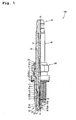
- a configuration of a reference spark plug 100 will be described.
- a direction of an axis "O" of the spark plug 100 is regarded as the top-to-bottom direction in the drawing.
- a lower side of the drawing is regarded as a front end side of the spark plug 100 and an upper side of the drawing is regarded as a rear end side of the spark plug 100.
- the spark plug 100 is generally comprised of an insulator 10, a metal shell 50, a center electrode 20, a cylindrical portion 60, a ground electrode 30 and a metal terminal fitting 40.
- the metal shell 50 holds the insulator 10 therein.
- the center electrode 20 extends in the axis "O" direction and is accommodated in an axial bore 12 of the insulator 10.
- the cylindrical portion 60 is provided in a front end portion of the metal shell 50.
- the ground electrode 30 has a base end portion 32 welded to a front end face 67 of cylindrical portion 60 and a front end portion 31 being bent so that an inner face 33 thereof faces a front end portion 22 of the center electrode 20.
- the metal terminal fitting 40 is provided at a rear end portion of the insulator 10.
- the cylindrical insulator 10 is made of sintered alumina or the like as is commonly known and includes the axial bore 12 extending along an axis "O".
- a flange portion 19 having the largest outer diameter is formed in a generally central area in the axis "O".
- a rear end side body portion 18 is formed on the rear end side (upper side in Fig. 1 ) with respect to the flange portion 19.
- a front end side body portion 17 having an outer diameter smaller than that of the rear end side body portion 18 is formed on the front end side (lower side in Fig. 1 ) with respect to the flange portion 19.
- an elongated leg portion 13 having an outer diameter smaller than that of the front end side body portion 17 is formed on the front end side with respect to the front end side body portion 17.
- the diameter of the elongated leg portion 13 is gradually tapered towards the front end side.
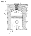
- the elongated leg portion 13 is exposed to a combustion chamber 77 (see Fig. 3 ) when the spark plug 100 is mounted on an engine head 70 of an internal combustion engine 1 (see Fig. 3 ).
- a step portion 15 is formed between the elongated leg portion 13 and the front end side body portion 17.
- the center electrode 20 assumes a generally columnar shape and is made of nickel-system alloys or the like such as INCONEL (trade name) 600 or 601 in which a metal core 23 comprised of copper or the like with excellent thermal conductivity is provided.
- the center electrode 20 is held in the front end side of the axial bore 12 of the insulator 10 so that an axis of the center electrode 20 is coaxially-arranged with the axis O of the spark plug 100.
- a front end side of the center electrode 20 projects from a front end face of a front end portion 11 of the insulator 10, and such projecting front portion is tapered towards the front end side.
- a noble metal tip 91 for improving resistance to spark erosion is welded to a front end of the projecting front portion and integrated with the center electrode 20 so as to constitute the front end portion 22 having small diameter.
- the "center electrode” includes the noble metal tip 91 integrated with the center electrode 20.
- center electrode 20 is electrically connected to the metal terminal fitting 40 on the rear end side through a seal material 4 and a ceramic resistance 3 both provided inside the axial bore 12.
- a high-tension cable (not shown) is connected to the metal terminal fitting 40 through a plug cap (not shown) where high voltage is applied.
- the ground electrode 30 is comprised of a metal having an excellent corrosion resistance.
- a nickel-system alloy such as INCONEL (trade name) 600 or 601 is used.
- the ground electrode 30 has a generally rectangular shape as seen from the cross-section in the longitudinal direction.
- the base end portion 32 of the ground electrode 30 is welded to the front end face 67 of the cylindrical portion 60.
- the front end portion 31 of the ground electrode 30 is bent so that one side face thereof faces the front end portion 22 of the center electrode 20 whereby a spark discharge gap is formed between the inner face 33 of the front end portion 31 and a front end face 21 of the center electrode 20 (the front end face 21 of the noble metal tip 91 in this embodiment).
- the metal shell 50 is a tubular metal fitting for fixing the spark plug 100 to the engine head 70 (see Fig. 2 ) of the internal combustion engine 1 (see Fig. 3 ) and holds and surrounds the insulator 10 therein.
- the metal shell 50 is comprised of a low carbon steel material and includes a tool engagement portion 51 and a fitting thread portion 52.
- the tool engagement portion 51 engages with a spark plug wrench (not shown).
- the fitting thread portion 52 assumes a male-thread shape to engage with a mounting portion 71 (refer to Fig. 2 ) of the engine head 70 provided in the upper part of the internal combustion engine 1.
- a flange-like seal portion 54 is formed between the tool engagement portion 51 and the fitting thread portion 52, and a gasket 5 for preventing air leakage in the engine is formed between the seal portion 54 and the fitting thread portion 52.
- a thin caulking portion 53 is formed on the rear end side with respect to the tool engagement portion 51 of the metal shell 50, and a thin buckling portion 58 is formed between the seal portion 54 and the tool engagement portion 51.
- Annular ring members 6, 7 lie between an inner circumferential face of the metal shell 50 where the tool engagement portion 51 and the caulking portion 53 are formed and an outer circumferential face of the rear end side body portions 18 of the insulator 10. Further, talc powder 9 is filled between both ring members 6, 7. The insulator 10 is pressed towards the front end side in the metal shell 50 through the ring members 6, 7 and the talc 9 by inwardly caulking an end portion of the caulking portion 53.
- a step portion 56 formed in an inner circumference of the metal shell 50 and corresponding to the fitting thread portion 52 supports the step portion 15 of the insulator 10 through an annular packing 8, thereby integrating the metal shell 50 and the insulator 10. At this time, the airtightness between the metal shell 50 and the insulator 10 is maintained by the packing 8.
- the buckling portion 58 is formed so as to outwardly deform with an application of compression force at the time of a caulking process. The buckling portion 58 provides a compression stroke of the talc 9 in order to improve the airtightness.
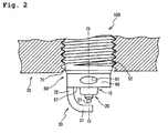
- the cylindrical portion 60 formed in the front end portion of the metal shell 50 will be described.
- the cylinder-shaped cylindrical portion 60 is provided in the front end portion of the metal shell 50.
- the cylindrical portion 60 projects into the combustion chamber from an inner wall face of the engine head 70 when the spark plug 100 is fixed to the mounting portion 71 of the engine head 70.
- the cylindrical portion 60 is formed so that the front end face 67 is disposed on the rear end side with respect to the front end face 21 of the center electrode 20.
- the base end portion 32 of the ground electrode 30 is joined to the front end face 67 of the cylindrical portion 60.
- a ventilating portion 61 comprised of a through hole that penetrates a side face of an inner circumference of the cylindrical portion 60 is formed on a side face of an outer circumference of the cylindrical portion 60.
- the ventilating portion 61 assumes an oval shape having a minor axis in a direction parallel to the axis O.
- a major axis of the ventilating portion 61 is 3.0mm
- the minor axis thereof is 1.5mm.
- the ventilating portion 61 is formed in a location away from a junction between the cylindrical portion 60 and the ground electrode 30 in a circumferential direction of the cylindrical portion 60. It is noted that the circumferential direction of the cylindrical portion 60 is a direction perpendicularly to the axis O direction.
- a thread starting position 55 formed on the fitting thread portion 52 of the metal shell 50 is brought into contact with a contact position 72 of the mounting portion 71 at the time of fixing the spark plug 100.
- a relative direction (angular phase) between the engine head 70 and the spark plug 100 after tightening the spark plug 100 is determined by specifying the starting position 55 and the contact position 72.
- the ventilating portion 61 is formed in a position facing to the inlet 73 of internal combustion engine 1 (right-hand side in Fig. 3 ) in the outer circumferential face of the cylindrical portion 60. It is noted that a fixing method of the spark plug 100 to the engine head 70 at the angular phase after tightening is one of the examples and is not limited to the above method.
- the air-fuel mixture flowing into the combustion chamber from the inlet 73 enters to inside of the cylindrical portion 60 through the ventilating portion 61 and hits the surface of the insulator 10 facing the ventilating portion 61.
- the air-fuel mixture takes the heat from the insulator 10 and cools it down. Therefore, a pre-ignition failure is likely to be prevented.
- the cylindrical portion 60 prevents the air-fuel mixture from directly hitting a surface of the insulator 10 which does not face the ventilating portion 61.
- carbon adhering to the surface of the insulator 10 can be reduced, thereby preventing an occurrence of so-called "carbon fouling".
- the ventilating portion 61 is formed in the position away from the junction between the ground electrode 30 and the cylindrical portion 60 in the circumferential direction of the cylindrical portion 60, the ground electrode 30 can join to a position away from a portion of the cylindrical portion 60 that has low rigidity due to the ventilating portion 61. Therefore, the endurance over vibration or a shock can improve. In addition, since the heat conduction from the ground electrode 30 to the rear end side of the metal shell 50 is not intercepted by the ventilating portion 61, heat conductivity of the ground electrode 30 through the cylindrical portion 60 can improve.
- the ventilating portion 61 is formed in the position facing to the inlet 73 of the internal combustion engine 1 in the outer circumferential face of the cylindrical portion 60. Thus, the air-fuel mixture is likely to hit the insulator 10 through the ventilating portion 61, thereby facilitating a cooling effect.
- the spark plug 200 according to this embodiment is provided with a ventilating portion 261 having a different shape from the ventilating portion 61 of the spark plug 100 according to Fig. 1 .
- ventilating portion 261 having a different shape from the ventilating portion 61 of the spark plug 100 according to Fig. 1 .
- ventilating portion 261 provided in a cylindrical portion 260 of a metal shell 250 of the spark plug 200.
- Other parts or portions of the spark plug 200 that are the same as those in the embodiment of Fig. 1 will be represented with the same reference numerals, and the description thereof shall be omitted or simplified.
- the cylindrical portion 260 is provided in the front end portion of the metal shell 250 of the spark plug 200 according to this embodiment.
- the cylindrical portion 260 projects into the combustion chamber from the inner wall face of the engine head 70.
- the base end 32 of the ground electrode 30 is joined to a front end face 267 of the cylindrical portion 260.
- the U-shaped notch 261 in a side view having a size of 2.5mm high (a direction parallel to the axis O) and 5.0 mm wide is formed in a position away from the junction between the ground electrode 30 and the cylindrical portion 260 in the circumferential direction of the cylindrical portion 260.
- An edge (dihedral angle portion) formed between a face forming the ventilating portion 261 and the inner circumferential face of the cylindrical portion 260 is not R-chamfered and has a sharp angle. Similar to the ventilating portion 61 of the spark plug 100 according to Fig. 1 , when the spark plug 200 is fixed to the mounting portion 71 of the engine head 70, the ventilating portion 261 is formed on a side (right-hand side in Fig.
- FIG. 3 facing to the inlet 73 of the internal combustion engine 1 (see Fig. 3 ) in the outer circumferential face of the cylindrical portion 260.
- another ventilating portion 261 is formed on a side (left-hand side in Fig. 3 ) facing to the exhaust port 74 (see Fig. 3 ) of the internal combustion engine 1 in the outer circumferential face of the cylindrical portion 260.
- the air-fuel mixture enters into the combustion chamber 77 from the inlet 73 at the time of driving the internal combustion engine 1 and flows toward the exhaust port 74.
- the air-fuel mixture enters into the inside of cylindrical portion 260 through the ventilating portion 261 of the cylindrical portion 260 disposed in a flowing path of the air-fuel mixture and hits the surface of the insulator 10 facing to the ventilating portion 261.
- the air-fuel mixture takes the heat of the insulator 10 and cools down the insulator 10. Since the angle of the edge formed between the face forming the ventilating portion 261 and the inner circumferential face of the cylindrical portion 260 is sharp, field intensity near the edge becomes large by forming the ventilating portion 261.
- the flashover produced at the rear end side of the elongated leg portion 13 of the insulator 10 can be prevented because the spark flies to the edge. Then, the carbon adhering to the surface of the insulator 10 can be cleaned. Since the air-fuel mixture flows into inside of the cylindrical portion 260 through the ventilating portion 261, the sparks tend to be exposed to the air-fuel mixture when the sparks fly to the edge of the ventilating portion 261, thereby readily igniting the air-fuel mixture. Furthermore, the flames can be smoothly propagated into the combustion chamber 77 through the ventilating portion 261.
- the spark plugs configured according to the above embodiments are subject to evaluation tests 1 to 3 as shown below.
- an evaluation test 1 a test on a relation between the presence/absence of the ventilating portion 61, 261 and an occurring timing of the pre-ignition was conducted.
- three spark plugs A, B and C each having different shape of the cylindrical portion that was provided in the front end portion of the metal shell were prepared.
- the spark plug A had no ventilating portion in the cylindrical portion.
- the spark plug B had an oval-shaped through hole in the cylindrical portion which is similar to the spark plug 100 according to the embodiment of Fig. 1 .
- the spark plug C had a U-shaped notch in the cylindrical portion which is similar to the spark plug 200 according to the embodiment of Fig. 4 .
- each spark plug was mounted on the engine head of the internal combustion engine, the engine was operated in a full-throttle state at 5600rpm of engine speed, and the ignition timing was gradually advanced to cause the pre-ignition. Then, an ignition timing where the earliest pre-ignition occurred and an ignition timing where the latest pre-ignition occurred were measured. It is noted that the ignition timing is represented as an angle before top-dead center (BTDC) of a crank, which moves a piston in the internal combustion engine. As the ignition timing where the earliest pre-ignition occurred and the ignition timing where the latest pre-ignition occurred were late - i.e., as the degree of BTDC was large - the spark plug had good heat conductivity and a higher thermal value.
- BTDC top-dead center
- the spark plug B exhibited that both ignition timings where the earliest and latest pre-ignitions occur were late compared to those of the spark plug A, and the spark plug B had good heat conductivity.
- the spark plug C exhibited that the ignition timings where the earliest and latest pre-ignitions occur were later, and the spark plug C had better heat conductivity.
- the reason why the spark plug C had better heat conductivity than that of the spark plug B was that the spark plug C had a ventilating portion larger than that of the spark plug B.
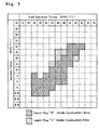
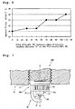
- a test on a relation between the presence/absence of the ventilating portion 261 and a combustion stability was conducted.
- the same spark plugs A and C as the first test were prepared.
- Each spark plug was mounted on the engine head of the internal combustion engine for the test, and the internal combustion engine was operated at different fuel injection timing and ignition timing.
- the combustion stability was examined as to whether or not any misfiring occurred.
- the result is shown in Fig. 5 .
- both the ignition timing and the fuel injection timing are represented as an angle before top-dead center (BTDC) of a crank.
- An area shaded with lines shows the stable combustion area of the spark plug A, and an area shaded with dots shows the stable combustion of the spark plug C.
- the spark plug C had a large stable combustion area compared to that of the spark plug A.
- the spark plug C exhibited an increased stable combustion area near the upper left in Fig. 5 where the carbon fouling tends to occur, compared to the spark plug A. This is because the sparks fly to the edge, which is provided by forming the ventilating portion in the cylindrical portion, and ignite the air-fuel mixture even though the side sparks are generated.
- the first virtual section S is a cross section including the front end portion of the cylindrical portion and perpendicular to the axis O direction.
- the diameter of the insulator 10 in the first virtual section S is shown as "L”
- a length tying both ends of the ventilating portion 261 (notch) in the first virtual section S is shown as "W”.
- "W” and "L” were defined as mentioned above, and six spark plugs each having a different ratio W/L (%) were prepared. More particularly, the similar test as the evaluation test 1 was conducted on the spark plugs each having the ratio W/L (%) of 0% (with no notch), 30%, 50%, 70%, 90% and 110%.
- the result of the evaluation test 3 is shown in Fig. 6 .
- the ignition timing when the pre-ignition occurs is represented as the angle BTDC of the crank.
- a first modification as shown in Fig. 7 has different shape and a different number of the ventilating portions, which are formed in the cylindrical portion provided in the front end portion of the metal shell, compared to that of the embodiment of Fig. 1 .
- Other compositions of the first modification are the same as that of the embodiment of Fig. 1 .
- a spark plug 300 according to the modification has eight ventilating portions 361 formed in the cylindrical portion 360 of the metal shell 350 and assuming a rectangular through hole shape in the axis O direction with the size of 2.5mm high (in the direction parallel to the axis O) and 1.0 mm wide.
- a ventilating portion 361 has a length in the axis O direction longer than a radial length thereof in the first modification, a lot of air-fuel mixture can flow from the ventilating portion 361 and the cooling effect on the insulator 10 improves.
- a plurality of ventilating portions comprised of a through hole or a notch may be employed.
- the ventilating portions are preferably provided in a position facing to at least the inlet of the internal combustion engine. Therefore, similar to the spark plug 200 of Fig. 4 , in the outer circumferential face of the cylindrical portion, the ventilating portion may be provided not only in a position facing to the inlet of the internal combustion engine but also in a position facing to the exhaust port of the internal combustion engine. In this way, the air-fuel mixture can flow near the insulator through the ventilating portion, thereby exerting the cooling effect on the insulator by the air-fuel mixture.
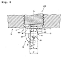
- a spark plug 400 according to the invention has a ventilating portion 461 in which a radial length thereof on the rear end side is shorter than that on the front end side. More particularly, as shown in Fig. 8 , a cylindrical portion 460 provided in the front end portion of a metal shell 450 includes a ventilating portion 461 (notch) that assumes a generally trapezoidal shape in the side view with the size of 2.5mm high (in a direction parallel to the axis O), 5.0mm width on the front end side and 3.0mm width on the rear end side. In this way, the shape and the size of ventilating portion comprised of a notch can be adequately altered.
- the notch in the side view has the radial length on the rear end side shorter than that on the front end side as in the spark plug 400. Further, as in the spark plug 400, a diameter "L" of the insulator 10 in a first virtual section "S" including the front end portion and perpendicular to the axis O direction is shorter than a length "W" tying both ends of the ventilating portion 461 in the first virtual section S.
- a diameter "M" of the insulator 10 in a second virtual section "T" including the rear end portion of a ventilating portion 461 and perpendicular to the axis O direction is longer than a length "V" tying both ends of the ventilating portion 461 in the second virtual section T.
- a shape of the ventilating portion where the radial length thereof on the rear end side is shorter than that on the front end side can be arbitrary selected.
- a triangular shape or a droplet shape can be adopted besides the generally trapezoidal shape in the side view according to the invention.
- an area where the ventilating portion (notch) is formed is preferably smaller than an area where no notch is formed, viewing the cylindrical portion from the front end side.
- the sum of the angles each formed between straight lines which tie each end of the notch to the center of cylindrical portion, respectively is preferably smaller than the sum of the angles each formed between straight lines which tie each end of the cylindrical portion to the center of cylindrical portion, respectively.
- the angle formed between the straight lines tying each end of the cylindrical portion 260 to the center P, respectively, in the first virtual section S means an angle facing to the cylindrical portion 260 among the angles formed between the straight lines which tie each end to the center P of cylindrical portion 260, respectively, in the first virtual section S.
- an angle " ⁇ " represents the angle formed between the straight lines which tie each end of the notch 261 to the center P, respectively, in the first virtual section S.
- the angle ⁇ is an acute angle
- the sum of angles ⁇ is smaller than the sum of angles ⁇ .
- the angle ⁇ may differ depending on whether the both ends of notch 261 in the first virtual section S are defined as the ends on the inner circumference side or the outer circumference side of the notch 261.
- the reason for specifying the above-mentioned formation range of the cylindrical portion 260 and that of the notch 261 in the first virtual section S is that the sufficient air-fuel mixture can flow into the center P through the notch 261. Therefore, the definition of the "both ends" of the notch 261 can be selected considering the flow of the air-fuel mixture.
- the both ends can be defined either the ends on the inner circumference side or the outer circumference side of the notch 261, or alternatively a combination thereof (i.e., one end is on the inner circumference side and the other end is on the outer circumference side of the notch 261).
- the same idea may be adapted to the "both ends" of cylindrical portion.
- a spark plug 500 according to this modification as shown in Fig. 10 , four ground electrodes all of which have the equal shape and size are joined to a front end face 567 of a cylindrical portion 560 that is provided in the front end portion of a metal shell 550.
- a ground electrode 530 is provided on the left-hand side in Fig.
- a ground electrode 535 is provided on the near side
- a ground electrode 537 is provided on the right-hand side
- another ground electrode (not illustrated) is provided on the far side, respectively.
- the spark discharge gap is formed between a front end portion 522 of a center electrode 520, which is held in an insulator 510, and the four ground electrodes, respectively.
- In the outer circumferential face of the cylindrical portion 560 in the spark plug 500 there is provided two oval-shaped ventilating portions 561 with the size of 2.0mm in the major axis and 1.5mm in the minor axis (a direction parallel to the axis O). In this way, the present invention can also be applied to a multi-ground-electrodes plug.
- the shape, size and a number of the ventilating portion can be defined arbitrarily.
- the angle phase after fixing the spark plug 100 to the mounting portion 71 is defined by specifying the thread starting position 55 and the contact position 72.
- other methods for defining the angle phase after fixing the spark plug 100 can also be employed.
- a thread-less plug that has no thread ridge in the metal shell.
- Such a thread-less plug is mounted on the internal combustion engine in such a manner that the plug is inserted in a mounting hole formed in the internal combustion engine while pressing towards the front end side with a fixing tool, and then the fixing tool is fixed to the engine head by a screw clamp or the like.
- an adequate angle phase can be readily determined at the time of inserting the plug in the mounting hole.
- the thread portion 52 may be further extended in the axis O direction so that a part of the thread portion 52 projects from the inner wall face of the engine head 70 when mounting the spark plug on the engine head 70. That is, even though the spark plug has the thread ridge formed in the cylindrical portion 60 thereof, the present invention is applicable.
- the spark plug is fixed perpendicularly to the inner wall face of the engine head 70, the present invention is applicable to a spark plug which is fixed aslant to the inner wall face.
- the present invention exhibits the cylindrical portion having the ventilating portion with the same shape at an equal interval therebetween, the present invention is not necessarily limited to the above-described embodiment.
- the size of the ventilating portion formed in the cylindrical portion may vary.
- the ventilating portion is preferably not to be formed near the portion to which the ground electrode is joined considering the heat conductivity of the ground electrode. Therefore, when the ventilating portion is formed along the circumferential direction of the cylindrical portion, the ventilating portion may be formed so that an opening area thereof is made gradually wider as it gets away from a junction with the ground electrode.
- the ventilating portion having a wide opening area preferably faces the inlet of the combustion chamber when the spark plug is mounted on the internal combustion engine.
Applications Claiming Priority (2)
| Application Number | Priority Date | Filing Date | Title |
|---|---|---|---|
| JP2007043599 | 2007-02-23 | ||
| PCT/JP2008/052943 WO2008102842A1 (ja) | 2007-02-23 | 2008-02-21 | スパークプラグ、及びスパークプラグを備えた内燃機関 |
Publications (3)
| Publication Number | Publication Date |
|---|---|
| EP2139081A1 EP2139081A1 (en) | 2009-12-30 |
| EP2139081A4 EP2139081A4 (en) | 2012-10-31 |
| EP2139081B1 true EP2139081B1 (en) | 2014-11-05 |
Family
ID=39710114
Family Applications (1)
| Application Number | Title | Priority Date | Filing Date |
|---|---|---|---|
| EP08711732.1A Not-in-force EP2139081B1 (en) | 2007-02-23 | 2008-02-21 | Spark plug and internal combustion engine with spark plug |
Country Status (4)
| Country | Link |
|---|---|
| US (1) | US7975665B2 (ja) |
| EP (1) | EP2139081B1 (ja) |
| JP (1) | JPWO2008102842A1 (ja) |
| WO (1) | WO2008102842A1 (ja) |
Families Citing this family (25)
| Publication number | Priority date | Publication date | Assignee | Title |
|---|---|---|---|---|
| US9229222B2 (en) | 2005-02-23 | 2016-01-05 | Pixtronix, Inc. | Alignment methods in fluid-filled MEMS displays |
| US8310442B2 (en) | 2005-02-23 | 2012-11-13 | Pixtronix, Inc. | Circuits for controlling display apparatus |
| US8519945B2 (en) | 2006-01-06 | 2013-08-27 | Pixtronix, Inc. | Circuits for controlling display apparatus |
| US9082353B2 (en) | 2010-01-05 | 2015-07-14 | Pixtronix, Inc. | Circuits for controlling display apparatus |
| US7999994B2 (en) | 2005-02-23 | 2011-08-16 | Pixtronix, Inc. | Display apparatus and methods for manufacture thereof |
| US9261694B2 (en) | 2005-02-23 | 2016-02-16 | Pixtronix, Inc. | Display apparatus and methods for manufacture thereof |
| US8159428B2 (en) | 2005-02-23 | 2012-04-17 | Pixtronix, Inc. | Display methods and apparatus |
| US9158106B2 (en) | 2005-02-23 | 2015-10-13 | Pixtronix, Inc. | Display methods and apparatus |
| US8482496B2 (en) | 2006-01-06 | 2013-07-09 | Pixtronix, Inc. | Circuits for controlling MEMS display apparatus on a transparent substrate |
| US20070205969A1 (en) | 2005-02-23 | 2007-09-06 | Pixtronix, Incorporated | Direct-view MEMS display devices and methods for generating images thereon |
| US8526096B2 (en) | 2006-02-23 | 2013-09-03 | Pixtronix, Inc. | Mechanical light modulators with stressed beams |
| US9176318B2 (en) | 2007-05-18 | 2015-11-03 | Pixtronix, Inc. | Methods for manufacturing fluid-filled MEMS displays |
| JP5045286B2 (ja) * | 2007-07-24 | 2012-10-10 | トヨタ自動車株式会社 | 内燃機関の点火装置 |
| US8169679B2 (en) | 2008-10-27 | 2012-05-01 | Pixtronix, Inc. | MEMS anchors |
| KR20120139854A (ko) | 2010-02-02 | 2012-12-27 | 픽스트로닉스 인코포레이티드 | 디스플레이 장치를 제어하기 위한 회로 |
| RU2496197C1 (ru) * | 2012-02-29 | 2013-10-20 | Общество С Ограниченной Ответственностью "Рефмашпром" (Ооо "Рефмашпром") | Свеча зажигания |
| JP2014007071A (ja) * | 2012-06-25 | 2014-01-16 | Nippon Soken Inc | 点火プラグ |
| JP5955668B2 (ja) | 2012-07-03 | 2016-07-20 | 株式会社日本自動車部品総合研究所 | 点火プラグ |
| US8823251B2 (en) * | 2012-07-06 | 2014-09-02 | Denso International America, Inc. | Partial shroud of spark plug for ground electrode heat dispersion |
| JP5971806B2 (ja) * | 2013-02-21 | 2016-08-17 | 日本特殊陶業株式会社 | プラズマジェット点火プラグ及びその製造方法 |
| US9134552B2 (en) | 2013-03-13 | 2015-09-15 | Pixtronix, Inc. | Display apparatus with narrow gap electrostatic actuators |
| JP6352043B2 (ja) * | 2014-05-08 | 2018-07-04 | 株式会社Soken | 内燃機関 |
| JP2017157451A (ja) | 2016-03-02 | 2017-09-07 | 日本特殊陶業株式会社 | 点火プラグ |
| WO2018213264A2 (en) * | 2017-05-15 | 2018-11-22 | Cummins Inc. | Combustion pre-chamber assemblies for an internal combustion engine |
| JP7330002B2 (ja) * | 2019-07-18 | 2023-08-21 | 株式会社Soken | スパークプラグ |
Citations (1)
| Publication number | Priority date | Publication date | Assignee | Title |
|---|---|---|---|---|
| US20050104495A1 (en) * | 2003-11-14 | 2005-05-19 | Denso Corporation | Spark plug having a plurality of center electrodes |
Family Cites Families (33)
| Publication number | Priority date | Publication date | Assignee | Title |
|---|---|---|---|---|
| US1373682A (en) * | 1921-04-05 | Spark-plug | ||
| US1527170A (en) * | 1922-10-10 | 1925-02-24 | Ray C Carver | Spark-plug protector |
| US2106449A (en) * | 1934-09-12 | 1938-01-25 | Charles R Boyd | Spark plug |
| US2272558A (en) * | 1940-06-18 | 1942-02-10 | Henry Carl | Spark plug |
| US2273651A (en) * | 1940-09-26 | 1942-02-17 | Thoma & Gould Sales Company | Spark plug |
| US2616406A (en) * | 1949-10-22 | 1952-11-04 | Vernon R Thomas | Spark plug |
| US2831993A (en) * | 1956-07-10 | 1958-04-22 | Champion Spark Plug Co | Igniter |
| JPS4936344U (ja) * | 1972-07-06 | 1974-03-30 | ||
| JPS4936344A (ja) | 1972-08-01 | 1974-04-04 | ||
| JPS5343143A (en) * | 1976-09-30 | 1978-04-19 | Tokai Trw & Co | Ignition plug |
| US4267482A (en) * | 1977-04-07 | 1981-05-12 | Nippon Soken, Inc. | Ignition spark plug |
| FR2492601A1 (fr) * | 1980-10-17 | 1982-04-23 | Eyquem | Bougie d'allumage par etincelles perfectionnee |
| JPH0634065B2 (ja) * | 1985-09-17 | 1994-05-02 | 株式会社東芝 | 原子力プラントの換気空調設備 |
| JPS6282684A (ja) | 1985-10-07 | 1987-04-16 | 株式会社デンソー | 内燃機関用点火プラグ |
| DE8908502U1 (ja) * | 1988-07-14 | 1989-09-07 | Park, Tae Hak, Suweonsi, Gyeong-Gi Do, Kr | |
| US5105780A (en) * | 1990-08-08 | 1992-04-21 | Caterpillar Inc. | Ignition assisting device for internal combustion engines |
| JPH04329284A (ja) * | 1991-05-01 | 1992-11-18 | Ngk Spark Plug Co Ltd | 発火部包囲電極を有するスパークプラグ |
| US5697334A (en) * | 1996-02-16 | 1997-12-16 | Alliedsignal Inc. | Spark plug with integral retainer nut |
| US6104130A (en) * | 1996-02-16 | 2000-08-15 | Alliedsignal Inc. | Radial gap high thread spark plug |
| US5799634A (en) * | 1997-03-03 | 1998-09-01 | Shifflette; J. Michael | Spark plug for venting excessive pressure |
| US6013973A (en) * | 1997-10-24 | 2000-01-11 | Sato; Jun | Spark plug having a sub-combustion chamber for use in fuel ignition systems |
| US5937813A (en) * | 1998-04-29 | 1999-08-17 | Shifflette; J. Michael | Resettable pressure relieving spark plug |
| JP2000277234A (ja) * | 1999-03-24 | 2000-10-06 | Nissan Motor Co Ltd | 内燃機関用点火プラグ |
| US6670740B2 (en) * | 1999-05-12 | 2003-12-30 | William W. Landon, Jr. | High electrical stiction spark plug |
| US6460506B1 (en) * | 2000-09-14 | 2002-10-08 | Caterpillar Inc. | Spark plug having an encapsulated electrode gap |
| US6382159B1 (en) * | 2000-10-13 | 2002-05-07 | J. Michael Shifflette | Temperature and pressure activated pressure relieving spark plug |
| AT410151B (de) * | 2001-06-05 | 2003-02-25 | Jenbacher Ag | Zündkerze einer brennkraftmaschine |
| US6882092B1 (en) * | 2003-05-20 | 2005-04-19 | Bill Nguyen | Jet nozzle spark plug |
| US8127741B2 (en) * | 2003-05-30 | 2012-03-06 | In Tae Johng | Ignition plugs for internal combustion engine |
| USD494136S1 (en) * | 2003-07-17 | 2004-08-10 | Justin P. Vesecky | Spark plug |
| GB2404422B (en) * | 2003-07-29 | 2006-07-05 | Federal Mogul Ignition Uk Ltd | Spark plug |
| JP4379370B2 (ja) * | 2005-04-08 | 2009-12-09 | 三菱自動車工業株式会社 | 内燃機関の燃焼室構造 |
| US7770552B2 (en) * | 2007-10-31 | 2010-08-10 | Caterpillar Inc. | Laser igniter having integral pre-combustion chamber |
-
2008
- 2008-02-21 EP EP08711732.1A patent/EP2139081B1/en not_active Not-in-force
- 2008-02-21 US US12/312,726 patent/US7975665B2/en not_active Expired - Fee Related
- 2008-02-21 WO PCT/JP2008/052943 patent/WO2008102842A1/ja active Application Filing
- 2008-02-21 JP JP2009500231A patent/JPWO2008102842A1/ja active Pending
Patent Citations (1)
| Publication number | Priority date | Publication date | Assignee | Title |
|---|---|---|---|---|
| US20050104495A1 (en) * | 2003-11-14 | 2005-05-19 | Denso Corporation | Spark plug having a plurality of center electrodes |
Also Published As
| Publication number | Publication date |
|---|---|
| WO2008102842A1 (ja) | 2008-08-28 |
| US20100101521A1 (en) | 2010-04-29 |
| EP2139081A4 (en) | 2012-10-31 |
| US7975665B2 (en) | 2011-07-12 |
| JPWO2008102842A1 (ja) | 2010-05-27 |
| EP2139081A1 (en) | 2009-12-30 |
Similar Documents
| Publication | Publication Date | Title |
|---|---|---|
| EP2139081B1 (en) | Spark plug and internal combustion engine with spark plug | |
| US8082897B2 (en) | Plasma jet ignition plug and ignition device for the same | |
| US8115371B2 (en) | Spark plug | |
| JP5149295B2 (ja) | スパークプラグ | |
| US9000658B2 (en) | Spark plug for internal combustion engine | |
| JP2005183177A (ja) | スパークプラグ | |
| EP3214706B1 (en) | Spark plug | |
| JP4270784B2 (ja) | スパークプラグ | |
| US10734791B2 (en) | Pre-chamber spark plug with surface discharge spark gap | |
| US11552456B1 (en) | Pre-chamber spark plug | |
| US7262547B2 (en) | Spark plug element having defined dimensional parameters for its insulator component | |
| US8558442B2 (en) | Plasma jet ignition plug | |
| EP2131036B1 (en) | Spark plug | |
| US8215277B2 (en) | Spark plug | |
| JP4457021B2 (ja) | スパークプラグ | |
| US8912715B2 (en) | Spark plug | |
| JP7183933B2 (ja) | スパークプラグ | |
| JP7039519B2 (ja) | 点火プラグ | |
| JP4480294B2 (ja) | スパークプラグの取付構造及びスパークプラグ | |
| JP2006260988A (ja) | スパークプラグ |
Legal Events
| Date | Code | Title | Description |
|---|---|---|---|
| PUAI | Public reference made under article 153(3) epc to a published international application that has entered the european phase |
Free format text: ORIGINAL CODE: 0009012 |
|
| 17P | Request for examination filed |
Effective date: 20090918 |
|
| AK | Designated contracting states |
Kind code of ref document: A1 Designated state(s): AT BE BG CH CY CZ DE DK EE ES FI FR GB GR HR HU IE IS IT LI LT LU LV MC MT NL NO PL PT RO SE SI SK TR |
|
| DAX | Request for extension of the european patent (deleted) | ||
| A4 | Supplementary search report drawn up and despatched |
Effective date: 20120927 |
|
| RIC1 | Information provided on ipc code assigned before grant |
Ipc: H01T 13/20 20060101AFI20120921BHEP |
|
| RAP1 | Party data changed (applicant data changed or rights of an application transferred) |
Owner name: NGK SPARK PLUG CO., LTD. |
|
| 17Q | First examination report despatched |
Effective date: 20130927 |
|
| GRAP | Despatch of communication of intention to grant a patent |
Free format text: ORIGINAL CODE: EPIDOSNIGR1 |
|
| RIC1 | Information provided on ipc code assigned before grant |
Ipc: H01T 13/20 20060101AFI20140305BHEP Ipc: H01T 13/16 20060101ALI20140305BHEP |
|
| INTG | Intention to grant announced |
Effective date: 20140324 |
|
| GRAP | Despatch of communication of intention to grant a patent |
Free format text: ORIGINAL CODE: EPIDOSNIGR1 |
|
| INTG | Intention to grant announced |
Effective date: 20140701 |
|
| GRAS | Grant fee paid |
Free format text: ORIGINAL CODE: EPIDOSNIGR3 |
|
| GRAA | (expected) grant |
Free format text: ORIGINAL CODE: 0009210 |
|
| AK | Designated contracting states |
Kind code of ref document: B1 Designated state(s): AT BE BG CH CY CZ DE DK EE ES FI FR GB GR HR HU IE IS IT LI LT LU LV MC MT NL NO PL PT RO SE SI SK TR |
|
| REG | Reference to a national code |
Ref country code: GB Ref legal event code: FG4D |
|
| REG | Reference to a national code |
Ref country code: CH Ref legal event code: EP |
|
| REG | Reference to a national code |
Ref country code: AT Ref legal event code: REF Ref document number: 695034 Country of ref document: AT Kind code of ref document: T Effective date: 20141115 |
|
| REG | Reference to a national code |
Ref country code: IE Ref legal event code: FG4D |
|
| REG | Reference to a national code |
Ref country code: DE Ref legal event code: R096 Ref document number: 602008035188 Country of ref document: DE Effective date: 20141211 |
|
| REG | Reference to a national code |
Ref country code: AT Ref legal event code: MK05 Ref document number: 695034 Country of ref document: AT Kind code of ref document: T Effective date: 20141105 |
|
| REG | Reference to a national code |
Ref country code: NL Ref legal event code: VDEP Effective date: 20141105 |
|
| REG | Reference to a national code |
Ref country code: LT Ref legal event code: MG4D |
|
| PG25 | Lapsed in a contracting state [announced via postgrant information from national office to epo] |
Ref country code: PT Free format text: LAPSE BECAUSE OF FAILURE TO SUBMIT A TRANSLATION OF THE DESCRIPTION OR TO PAY THE FEE WITHIN THE PRESCRIBED TIME-LIMIT Effective date: 20150305 Ref country code: NL Free format text: LAPSE BECAUSE OF FAILURE TO SUBMIT A TRANSLATION OF THE DESCRIPTION OR TO PAY THE FEE WITHIN THE PRESCRIBED TIME-LIMIT Effective date: 20141105 Ref country code: IS Free format text: LAPSE BECAUSE OF FAILURE TO SUBMIT A TRANSLATION OF THE DESCRIPTION OR TO PAY THE FEE WITHIN THE PRESCRIBED TIME-LIMIT Effective date: 20150305 Ref country code: NO Free format text: LAPSE BECAUSE OF FAILURE TO SUBMIT A TRANSLATION OF THE DESCRIPTION OR TO PAY THE FEE WITHIN THE PRESCRIBED TIME-LIMIT Effective date: 20150205 Ref country code: ES Free format text: LAPSE BECAUSE OF FAILURE TO SUBMIT A TRANSLATION OF THE DESCRIPTION OR TO PAY THE FEE WITHIN THE PRESCRIBED TIME-LIMIT Effective date: 20141105 Ref country code: FI Free format text: LAPSE BECAUSE OF FAILURE TO SUBMIT A TRANSLATION OF THE DESCRIPTION OR TO PAY THE FEE WITHIN THE PRESCRIBED TIME-LIMIT Effective date: 20141105 Ref country code: LT Free format text: LAPSE BECAUSE OF FAILURE TO SUBMIT A TRANSLATION OF THE DESCRIPTION OR TO PAY THE FEE WITHIN THE PRESCRIBED TIME-LIMIT Effective date: 20141105 |
|
| PG25 | Lapsed in a contracting state [announced via postgrant information from national office to epo] |
Ref country code: AT Free format text: LAPSE BECAUSE OF FAILURE TO SUBMIT A TRANSLATION OF THE DESCRIPTION OR TO PAY THE FEE WITHIN THE PRESCRIBED TIME-LIMIT Effective date: 20141105 Ref country code: LV Free format text: LAPSE BECAUSE OF FAILURE TO SUBMIT A TRANSLATION OF THE DESCRIPTION OR TO PAY THE FEE WITHIN THE PRESCRIBED TIME-LIMIT Effective date: 20141105 Ref country code: SE Free format text: LAPSE BECAUSE OF FAILURE TO SUBMIT A TRANSLATION OF THE DESCRIPTION OR TO PAY THE FEE WITHIN THE PRESCRIBED TIME-LIMIT Effective date: 20141105 Ref country code: HR Free format text: LAPSE BECAUSE OF FAILURE TO SUBMIT A TRANSLATION OF THE DESCRIPTION OR TO PAY THE FEE WITHIN THE PRESCRIBED TIME-LIMIT Effective date: 20141105 Ref country code: PL Free format text: LAPSE BECAUSE OF FAILURE TO SUBMIT A TRANSLATION OF THE DESCRIPTION OR TO PAY THE FEE WITHIN THE PRESCRIBED TIME-LIMIT Effective date: 20141105 Ref country code: GR Free format text: LAPSE BECAUSE OF FAILURE TO SUBMIT A TRANSLATION OF THE DESCRIPTION OR TO PAY THE FEE WITHIN THE PRESCRIBED TIME-LIMIT Effective date: 20150206 Ref country code: CY Free format text: LAPSE BECAUSE OF FAILURE TO SUBMIT A TRANSLATION OF THE DESCRIPTION OR TO PAY THE FEE WITHIN THE PRESCRIBED TIME-LIMIT Effective date: 20141105 |
|
| PG25 | Lapsed in a contracting state [announced via postgrant information from national office to epo] |
Ref country code: RO Free format text: LAPSE BECAUSE OF FAILURE TO SUBMIT A TRANSLATION OF THE DESCRIPTION OR TO PAY THE FEE WITHIN THE PRESCRIBED TIME-LIMIT Effective date: 20141105 Ref country code: DK Free format text: LAPSE BECAUSE OF FAILURE TO SUBMIT A TRANSLATION OF THE DESCRIPTION OR TO PAY THE FEE WITHIN THE PRESCRIBED TIME-LIMIT Effective date: 20141105 Ref country code: SK Free format text: LAPSE BECAUSE OF FAILURE TO SUBMIT A TRANSLATION OF THE DESCRIPTION OR TO PAY THE FEE WITHIN THE PRESCRIBED TIME-LIMIT Effective date: 20141105 Ref country code: CZ Free format text: LAPSE BECAUSE OF FAILURE TO SUBMIT A TRANSLATION OF THE DESCRIPTION OR TO PAY THE FEE WITHIN THE PRESCRIBED TIME-LIMIT Effective date: 20141105 Ref country code: EE Free format text: LAPSE BECAUSE OF FAILURE TO SUBMIT A TRANSLATION OF THE DESCRIPTION OR TO PAY THE FEE WITHIN THE PRESCRIBED TIME-LIMIT Effective date: 20141105 |
|
| REG | Reference to a national code |
Ref country code: DE Ref legal event code: R097 Ref document number: 602008035188 Country of ref document: DE |
|
| PLBE | No opposition filed within time limit |
Free format text: ORIGINAL CODE: 0009261 |
|
| STAA | Information on the status of an ep patent application or granted ep patent |
Free format text: STATUS: NO OPPOSITION FILED WITHIN TIME LIMIT |
|
| PG25 | Lapsed in a contracting state [announced via postgrant information from national office to epo] |
Ref country code: LU Free format text: LAPSE BECAUSE OF FAILURE TO SUBMIT A TRANSLATION OF THE DESCRIPTION OR TO PAY THE FEE WITHIN THE PRESCRIBED TIME-LIMIT Effective date: 20150221 |
|
| REG | Reference to a national code |
Ref country code: CH Ref legal event code: PL |
|
| 26N | No opposition filed |
Effective date: 20150806 |
|
| GBPC | Gb: european patent ceased through non-payment of renewal fee |
Effective date: 20150221 |
|
| PG25 | Lapsed in a contracting state [announced via postgrant information from national office to epo] |
Ref country code: LI Free format text: LAPSE BECAUSE OF NON-PAYMENT OF DUE FEES Effective date: 20150228 Ref country code: CH Free format text: LAPSE BECAUSE OF NON-PAYMENT OF DUE FEES Effective date: 20150228 Ref country code: MC Free format text: LAPSE BECAUSE OF FAILURE TO SUBMIT A TRANSLATION OF THE DESCRIPTION OR TO PAY THE FEE WITHIN THE PRESCRIBED TIME-LIMIT Effective date: 20141105 |
|
| REG | Reference to a national code |
Ref country code: IE Ref legal event code: MM4A |
|
| PG25 | Lapsed in a contracting state [announced via postgrant information from national office to epo] |
Ref country code: IT Free format text: LAPSE BECAUSE OF FAILURE TO SUBMIT A TRANSLATION OF THE DESCRIPTION OR TO PAY THE FEE WITHIN THE PRESCRIBED TIME-LIMIT Effective date: 20141105 |
|
| REG | Reference to a national code |
Ref country code: FR Ref legal event code: PLFP Year of fee payment: 9 |
|
| PG25 | Lapsed in a contracting state [announced via postgrant information from national office to epo] |
Ref country code: IE Free format text: LAPSE BECAUSE OF NON-PAYMENT OF DUE FEES Effective date: 20150221 Ref country code: GB Free format text: LAPSE BECAUSE OF NON-PAYMENT OF DUE FEES Effective date: 20150221 |
|
| PG25 | Lapsed in a contracting state [announced via postgrant information from national office to epo] |
Ref country code: SI Free format text: LAPSE BECAUSE OF FAILURE TO SUBMIT A TRANSLATION OF THE DESCRIPTION OR TO PAY THE FEE WITHIN THE PRESCRIBED TIME-LIMIT Effective date: 20141105 |
|
| PG25 | Lapsed in a contracting state [announced via postgrant information from national office to epo] |
Ref country code: MT Free format text: LAPSE BECAUSE OF FAILURE TO SUBMIT A TRANSLATION OF THE DESCRIPTION OR TO PAY THE FEE WITHIN THE PRESCRIBED TIME-LIMIT Effective date: 20141105 |
|
| REG | Reference to a national code |
Ref country code: FR Ref legal event code: PLFP Year of fee payment: 10 |
|
| PG25 | Lapsed in a contracting state [announced via postgrant information from national office to epo] |
Ref country code: HU Free format text: LAPSE BECAUSE OF FAILURE TO SUBMIT A TRANSLATION OF THE DESCRIPTION OR TO PAY THE FEE WITHIN THE PRESCRIBED TIME-LIMIT; INVALID AB INITIO Effective date: 20080221 Ref country code: BG Free format text: LAPSE BECAUSE OF FAILURE TO SUBMIT A TRANSLATION OF THE DESCRIPTION OR TO PAY THE FEE WITHIN THE PRESCRIBED TIME-LIMIT Effective date: 20141105 |
|
| PG25 | Lapsed in a contracting state [announced via postgrant information from national office to epo] |
Ref country code: TR Free format text: LAPSE BECAUSE OF FAILURE TO SUBMIT A TRANSLATION OF THE DESCRIPTION OR TO PAY THE FEE WITHIN THE PRESCRIBED TIME-LIMIT Effective date: 20141105 |
|
| PG25 | Lapsed in a contracting state [announced via postgrant information from national office to epo] |
Ref country code: BE Free format text: LAPSE BECAUSE OF FAILURE TO SUBMIT A TRANSLATION OF THE DESCRIPTION OR TO PAY THE FEE WITHIN THE PRESCRIBED TIME-LIMIT Effective date: 20141105 |
|
| REG | Reference to a national code |
Ref country code: FR Ref legal event code: PLFP Year of fee payment: 11 |
|
| PGFP | Annual fee paid to national office [announced via postgrant information from national office to epo] |
Ref country code: FR Payment date: 20190111 Year of fee payment: 12 |
|
| PG25 | Lapsed in a contracting state [announced via postgrant information from national office to epo] |
Ref country code: FR Free format text: LAPSE BECAUSE OF NON-PAYMENT OF DUE FEES Effective date: 20200229 |
|
| PGFP | Annual fee paid to national office [announced via postgrant information from national office to epo] |
Ref country code: DE Payment date: 20210209 Year of fee payment: 14 |
|
| REG | Reference to a national code |
Ref country code: DE Ref legal event code: R119 Ref document number: 602008035188 Country of ref document: DE |
|
| PG25 | Lapsed in a contracting state [announced via postgrant information from national office to epo] |
Ref country code: DE Free format text: LAPSE BECAUSE OF NON-PAYMENT OF DUE FEES Effective date: 20220901 |