EP2139013A1 - Elément de fonction - Google Patents
Elément de fonction Download PDFInfo
- Publication number
- EP2139013A1 EP2139013A1 EP09164025A EP09164025A EP2139013A1 EP 2139013 A1 EP2139013 A1 EP 2139013A1 EP 09164025 A EP09164025 A EP 09164025A EP 09164025 A EP09164025 A EP 09164025A EP 2139013 A1 EP2139013 A1 EP 2139013A1
- Authority
- EP
- European Patent Office
- Prior art keywords
- translucent
- laser
- front cover
- layer
- light
- Prior art date
- Legal status (The legal status is an assumption and is not a legal conclusion. Google has not performed a legal analysis and makes no representation as to the accuracy of the status listed.)
- Granted
Links
- 238000000034 method Methods 0.000 claims abstract description 17
- 238000004519 manufacturing process Methods 0.000 claims abstract description 13
- 239000000463 material Substances 0.000 claims description 37
- 238000003466 welding Methods 0.000 claims description 27
- 239000004033 plastic Substances 0.000 claims description 15
- 229920003023 plastic Polymers 0.000 claims description 15
- 238000010422 painting Methods 0.000 claims description 4
- 238000005286 illumination Methods 0.000 claims description 3
- 238000002347 injection Methods 0.000 claims description 3
- 239000007924 injection Substances 0.000 claims description 3
- 238000001746 injection moulding Methods 0.000 claims description 3
- 238000007639 printing Methods 0.000 claims description 3
- 238000005507 spraying Methods 0.000 claims description 3
- 239000012815 thermoplastic material Substances 0.000 claims description 2
- 239000012780 transparent material Substances 0.000 claims description 2
- 238000000926 separation method Methods 0.000 claims 1
- 229920001169 thermoplastic Polymers 0.000 claims 1
- 239000004416 thermosoftening plastic Substances 0.000 claims 1
- 238000007740 vapor deposition Methods 0.000 claims 1
- 238000005034 decoration Methods 0.000 abstract 1
- 230000000694 effects Effects 0.000 description 18
- 230000003287 optical effect Effects 0.000 description 12
- 239000000243 solution Substances 0.000 description 8
- 238000011144 upstream manufacturing Methods 0.000 description 4
- 230000005540 biological transmission Effects 0.000 description 3
- 238000010304 firing Methods 0.000 description 3
- 230000015572 biosynthetic process Effects 0.000 description 2
- 238000005530 etching Methods 0.000 description 2
- 230000008020 evaporation Effects 0.000 description 2
- 238000001704 evaporation Methods 0.000 description 2
- 239000003973 paint Substances 0.000 description 2
- 238000003825 pressing Methods 0.000 description 2
- 238000002604 ultrasonography Methods 0.000 description 2
- 238000000149 argon plasma sintering Methods 0.000 description 1
- 239000003086 colorant Substances 0.000 description 1
- 230000001419 dependent effect Effects 0.000 description 1
- 239000003292 glue Substances 0.000 description 1
- 238000003780 insertion Methods 0.000 description 1
- 230000037431 insertion Effects 0.000 description 1
- 239000004922 lacquer Substances 0.000 description 1
- 238000003801 milling Methods 0.000 description 1
- 238000000465 moulding Methods 0.000 description 1
- 238000007649 pad printing Methods 0.000 description 1
- 238000002360 preparation method Methods 0.000 description 1
- 238000007650 screen-printing Methods 0.000 description 1
- 210000002023 somite Anatomy 0.000 description 1
- 238000010025 steaming Methods 0.000 description 1
Images


Classifications
-
- H—ELECTRICITY
- H01—ELECTRIC ELEMENTS
- H01H—ELECTRIC SWITCHES; RELAYS; SELECTORS; EMERGENCY PROTECTIVE DEVICES
- H01H9/00—Details of switching devices, not covered by groups H01H1/00 - H01H7/00
- H01H9/18—Distinguishing marks on switches, e.g. for indicating switch location in the dark; Adaptation of switches to receive distinguishing marks
- H01H9/182—Illumination of the symbols or distinguishing marks
-
- B—PERFORMING OPERATIONS; TRANSPORTING
- B60—VEHICLES IN GENERAL
- B60Q—ARRANGEMENT OF SIGNALLING OR LIGHTING DEVICES, THE MOUNTING OR SUPPORTING THEREOF OR CIRCUITS THEREFOR, FOR VEHICLES IN GENERAL
- B60Q3/00—Arrangement of lighting devices for vehicle interiors; Lighting devices specially adapted for vehicle interiors
- B60Q3/10—Arrangement of lighting devices for vehicle interiors; Lighting devices specially adapted for vehicle interiors for dashboards
- B60Q3/14—Arrangement of lighting devices for vehicle interiors; Lighting devices specially adapted for vehicle interiors for dashboards lighting through the surface to be illuminated
-
- G—PHYSICS
- G09—EDUCATION; CRYPTOGRAPHY; DISPLAY; ADVERTISING; SEALS
- G09F—DISPLAYING; ADVERTISING; SIGNS; LABELS OR NAME-PLATES; SEALS
- G09F13/00—Illuminated signs; Luminous advertising
- G09F13/04—Signs, boards or panels, illuminated from behind the insignia
-
- B—PERFORMING OPERATIONS; TRANSPORTING
- B60—VEHICLES IN GENERAL
- B60K—ARRANGEMENT OR MOUNTING OF PROPULSION UNITS OR OF TRANSMISSIONS IN VEHICLES; ARRANGEMENT OR MOUNTING OF PLURAL DIVERSE PRIME-MOVERS IN VEHICLES; AUXILIARY DRIVES FOR VEHICLES; INSTRUMENTATION OR DASHBOARDS FOR VEHICLES; ARRANGEMENTS IN CONNECTION WITH COOLING, AIR INTAKE, GAS EXHAUST OR FUEL SUPPLY OF PROPULSION UNITS IN VEHICLES
- B60K2360/00—Indexing scheme associated with groups B60K35/00 or B60K37/00 relating to details of instruments or dashboards
- B60K2360/20—Optical features of instruments
- B60K2360/33—Illumination features
-
- H—ELECTRICITY
- H01—ELECTRIC ELEMENTS
- H01H—ELECTRIC SWITCHES; RELAYS; SELECTORS; EMERGENCY PROTECTIVE DEVICES
- H01H2219/00—Legends
- H01H2219/054—Optical elements
- H01H2219/056—Diffuser; Uneven surface
-
- H—ELECTRICITY
- H01—ELECTRIC ELEMENTS
- H01H—ELECTRIC SWITCHES; RELAYS; SELECTORS; EMERGENCY PROTECTIVE DEVICES
- H01H2221/00—Actuators
- H01H2221/07—Actuators transparent
- H01H2221/0702—Transparent key containing three dimensional (3D) element
Definitions
- the invention relates to a functional element for control or display panels such as on the dashboard of a motor vehicle or the control panels of a machine.
- dashboards of motor vehicles such functional elements usually consist of a sleeve-shaped, rectangular, guide body whose front open side of a front cover is closed, on which the desired symbol should be visible.
- the guide body is used for positive insertion into a surrounding structure - usually the control panel - and is there either locked firmly - if it is an immovable functional element - or in the depth direction positively guided and on the back by means of z.
- the gap in the opaque layer can either be generated by its application by a suitable printing process such as pad printing screen printing or the opaque layer is first applied continuously and then removed by means of etching, lasers or the like, but always had the disadvantage that then The underlying, transparent material was usually slightly discolored, be it by the etchant or by the high-energy laser beam.
- front cover and guide body are made separately and connected to each other after the passage of light.
- either the translucent front panel can be colored in a particular color, without losing their translucency, or - which for the production of different colors the simpler solution is - after production of the finished light transmission, a color layer of translucent material in the desired color is placed over the light passage from the back and can also extend over the entire back of the front cover, including the remaining opaque layer away so that the application by means of painting, printing or steaming is not a problem.
- a recessed structure can theoretically be done in a variety of ways, such as hot stamping or master molding in making the front cover, but is preferably also produced by laser bombardment from the back after the opaque layer has been removed in the desired area.
- an optical three-dimensional effect can also be achieved by a raised structure relative to the back of the translucent faceplate, which can be done by laser by burning away the surrounding material of the faceplate around the desired raised structure.
- a blackening of these other surface areas around the raised structure is preferably likewise carried out by means of laser bombardment, in which the energy of the laser is set so high relative to the point of impact that blackening of the plastic material occurs there Processing of the surface of the recessed or raised structure by means of laser energy - especially when removing the last layer - must be adjusted so that the translucent property of the surface of the raised or recessed structure is maintained.
- the recessed structures may have at least one lenticular bottom or be lenticular in cross-section so that upon backlighting the light is scattered outwardly and may be viewed substantially equally well from different directions.
- the cross-section of a raised structure as a whole can also have such a convex lens effect, which accordingly can be directed at a particular viewing point as the focal point of the lens action, from which then the symbol can be seen particularly well or even only from this viewing point.
- the same can be achieved in a plurality of juxtaposed elevations with lens effect in that all are focused on a common focal point and aligned.
- the light rays of the backlight are reflected and concentrated at the bottom of the blind hole-shaped bullet hole into the translucent layer inside.
- the three-dimensional effect can be further enhanced by extending obliquely to the main plane of the front panel side walls of a recessed structure.
- the grading is so small that it is usually no longer visible to the naked eye.
- one and the same symbol or even two different symbols can be produced by laser bombardment from two different firing directions and then by appropriate illumination with directional light, for example, in each case a light-emitting diode with an upstream aperture device, by only one of the two symbols being lit alternately.
- cavities ie recessed structures in the back of this layer, can also be produced in a lower, covered layer without impairing the overlying layer by bombarding each layer by means of a laser of the corresponding wavelength.
- the front cover consists, in addition to the translucent layer in which the symbol is produced, of a welding frame made of opaque, eg. B. black, plastic, which is preferably the same material as the material of the guide body.
- a welding frame made of opaque, eg. B. black, plastic, which is preferably the same material as the material of the guide body.
- the front cover on the front open end face of the guide body is fixed by welding, preferably by means of ultrasound or by laser.
- welding projections are provided on the back of the welding frame, which form the welding material, which causes the welding or bonding when heated by means of ultrasound.
- the front plate and the welding frame are preferably formed integrally with each other and produced by a multi-stage injection process.
- This crossing point can be moved by appropriate control of the laser three-dimensionally inside the front panel, so that there the desired three-dimensional image is generated.
- FIG. 1 shows the finished manufactured functional element 1 with its plate-shaped front cover 3, which may be flat or curved both on the front or back and in which from the back of the front cover 3 in the depth direction 10, which extends at least forwardly open guide body 2.
- the guide body - as best of the longitudinal section of FIG. 2 shows - even at the rear end open and has only at the front end on a radially outwardly projecting edge 2a.
- the two parts are integrally connected to each other by means of ultrasonic welding, which is why prior to welding 3 'of the front cover 3 projecting weld projections 9 to the rear, which represent the welding material for ultrasonic welding and the introduction of ultrasonic vibrations under pressure and pressing against each other the two parts are heated and glue or weld the two parts against each other.
- the front cover 3 mainly consists of a translucent front plate 3a, one would be able to recognize this welding from the front through the translucent front plate 3a, which is generally permeable over its entire surface.
- Welding frame 3b and translucent front panel 3a are usually made in one piece with each other in a multi-stage plastic injection molding process.
- the back of the transparent front plate 3a is covered with an opaque layer 3c, which has one or more light passages 4 in the form of the desired symbol.
- These light passages 4 may be only an interruption in the opaque layer 3c or additionally a raised relative to the translucent front panel 3 or - as in FIG. 2 illustrated - a recessed structure 5 in the region of the passage 4 include.
- a light source such as a light emitting diode 6 for backlighting of the symbol, so already created solely by the thickness of the light-transmitting passage 4 mounted transparent front plate 3a, a three-dimensional effect of this symbol.
- a material removal by means of laser has the disadvantage that the surface of the remaining material is usually darkened by the heat development of the laser at the point of impact - which causes only the evaporation or burning of the material.
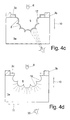
- FIGS. 4 and 5 show the front cover 3.
- the front covers 3 are backlit from their back 3 'by means of a diode 6 and have on their back an opaque layer 3c, which as a light passage 4 an interruption, ie gap in the form of the desired symbol, so that the viewer backlit this Can recognize symbol in the shape of the gap and a 3D effect in the depth direction 10 alone due to the thickness of the upstream transparent front plate 3 a occurs, as in Figure 4e shown.
- This depth effect is amplified in different ways.
- FIG. 4a For example, from the left, in cross-section conical, recessed, structure 5 clearly visible that this - viewed from a lying in front of the front panel 3a viewing point 20 - appears optically three-dimensional, ie a depth effect in the depth direction 10 results, depending on the Position of the viewing point 20 in the transverse direction 11 is more or less strong.
- the light of the light emitting diode 6 is largely reflected at these side walls 7 and only at the bottom 14 of the recessed structure 5 in FIG the front plate 3a penetrate.
- This effect can be used, for example, that from a previously defined point of view, for example, the eyes of the driver of a motor vehicle, this icon is particularly clearly visible, from the passenger's position, however, is less intense or even completely invisible.
- FIG. 4b shows a recessed structure 5, in which the removal of material in the front plate 3a successively in layers 15a, b was made deeper into the material, wherein the first layer to be removed is that of the opaque layer 3c.
- a sloping side wall results in a particularly strong optical depth.
- the grading which is exaggerated here, is low when ablated by laser and layers of a few 1/10 or 1 / 100mm thick, that they are usually not visible to the naked eye.
- a leveling of the stepped elevations can be carried out by subsequent oblique bombardment by laser in a firing direction parallel to the oblique position of the stepped side wall 7.
- a fully functional hologram can also be incorporated into the front panel 3a, in particular the rear 3 '.
- a light scattering towards the viewer can be achieved and thus an equally good recognizability of different viewpoints 20 distributed in the transverse direction 11 when either the recessed structure 5 has a total of a concave lenticular shape or / and it is composed of concave depressions 18, each fulfilling a lenticular function.
- FIG. 4f shows the formation of convex elevations 8 substantially side by side in the main plane of the back 3 ', but each pivoted so that all these convex protrusions 8' have a common focal point, namely the predetermined, prospective viewing point 20 of the user.
- FIG. 4f shows a dashed line, a single raised lenticular contour 5 with in cross section a single survey 8, which also bundles the light of the backlighting to a specific observation point and thus performs substantially the same function.
- the remaining opaque layer 3c may be either a pre-applied opaque paint or plastic burned or otherwise removed by the reader in the region of the symbol, or it may be at be the reader processing by targeted energy input blackened layer of the material of the mold plate 3a.
- the two structures 5.1 and 5.2 can overlap completely or partially, and be identical in shape but offset from each other depending on whether they are made visible simultaneously or alternately or are seen simultaneously or alternately by the viewer.
- the backlighting is done from the back by means of a light-emitting diode 6, due to the different ones
- Shooting directions 13.1 and 13.2 of the two lasers 12.1 and 12.2 are the two symbols in the form of the recessed structures 5.1 and 5.2 of different viewing points 20.1 and 20.2 - which are preferably each on the extension of the direction of bombardment of the laser forward - from each recognize different degrees well, the other symbol is much fainter or barely visible.
- FIG. 5c achieved with only a single translucent front panel 3a, characterized in that the two different recessed structures 5.1 and 5.2 are generated by different laser Beschussraumen 13.1, 13.2 and the backlighting with directional light, ie in particular two different LEDs 6.1 and 6.2 and optionally upstream aperture devices 16.1 and 16.2, illuminated.
Landscapes
- Engineering & Computer Science (AREA)
- Mechanical Engineering (AREA)
- Physics & Mathematics (AREA)
- General Physics & Mathematics (AREA)
- Theoretical Computer Science (AREA)
- Illuminated Signs And Luminous Advertising (AREA)
Applications Claiming Priority (1)
| Application Number | Priority Date | Filing Date | Title |
|---|---|---|---|
| DE102008030507A DE102008030507B3 (de) | 2008-06-27 | 2008-06-27 | Funktionselement |
Publications (2)
| Publication Number | Publication Date |
|---|---|
| EP2139013A1 true EP2139013A1 (fr) | 2009-12-30 |
| EP2139013B1 EP2139013B1 (fr) | 2013-08-14 |
Family
ID=41170921
Family Applications (1)
| Application Number | Title | Priority Date | Filing Date |
|---|---|---|---|
| EP09164025.0A Active EP2139013B1 (fr) | 2008-06-27 | 2009-06-29 | Elément de fonction |
Country Status (2)
| Country | Link |
|---|---|
| EP (1) | EP2139013B1 (fr) |
| DE (1) | DE102008030507B3 (fr) |
Cited By (6)
| Publication number | Priority date | Publication date | Assignee | Title |
|---|---|---|---|---|
| EP2676841A1 (fr) * | 2012-06-21 | 2013-12-25 | International Automotive Components Group GmbH | Composant d'habillage pouvant être éclairé pour un véhicule et procédé de fabrication de celui-ci |
| WO2016071063A1 (fr) * | 2014-11-06 | 2016-05-12 | Lisa Dräxlmaier GmbH | Dispositif d'éclairage |
| DE102015201936A1 (de) | 2015-02-04 | 2016-08-04 | Bayerische Motoren Werke Aktiengesellschaft | Holografische Anzeigevorrichtung |
| DE102018213974A1 (de) * | 2018-08-20 | 2020-02-20 | Bayerische Motoren Werke Aktiengesellschaft | Kunststoffblende mit Maskierschicht |
| DE102020112777A1 (de) | 2020-05-12 | 2021-11-18 | Audi Aktiengesellschaft | Bedienvorrichtung für ein Kraftfahrzeug |
| US12304123B2 (en) | 2021-02-23 | 2025-05-20 | Srg Global Liria, S.L. | Pedestrian safe front panel/grille having a two-shot molded decorative part |
Families Citing this family (3)
| Publication number | Priority date | Publication date | Assignee | Title |
|---|---|---|---|---|
| DE102016220069B4 (de) | 2016-10-14 | 2022-08-04 | Audi Ag | Beleuchtbare Verkleidungsvorrichtung für einen Innenraum eines Kraftfahrzeugs |
| DE102017120532A1 (de) * | 2017-09-06 | 2019-03-07 | Byton Limited | Leuchtvorrichtung für ein Fahrzeug, insbesondere Elektrofahrzeug |
| DE102024112176B3 (de) | 2024-04-30 | 2025-10-16 | Audi Aktiengesellschaft | Bedienelement aufweisend einen von einem transparenten Grundkörper teils umschlossenen Symbolkörper, Bedienvorrichtung, Kraftfahrzeug mit einer Bedienvorrichtung sowie Herstellungsverfahren für ein solches Bedienelement |
Citations (7)
| Publication number | Priority date | Publication date | Assignee | Title |
|---|---|---|---|---|
| DE19958582A1 (de) * | 1999-12-04 | 2001-06-21 | Daimler Chrysler Ag | Elektrischer Schalter |
| WO2002047933A1 (fr) * | 2000-12-15 | 2002-06-20 | Robert Bosch Gmbh | Procede de production d'un element de reglage et element de reglage |
| DE10250675A1 (de) * | 2002-10-31 | 2004-05-19 | Hella Kg Hueck & Co. | Anzeigeneinheit, isbesondere für Kraftfahrzeuge |
| EP1614586A2 (fr) * | 2004-07-05 | 2006-01-11 | Hella KGaA Hueck & Co. | Indicateur lumineux pour véhicules |
| US20060267788A1 (en) * | 2005-01-21 | 2006-11-30 | Delany George B | Method and apparatus for illuminating a wall plate |
| DE102007029314A1 (de) * | 2006-09-22 | 2008-04-03 | Preh Gmbh | Kappe für ein Anzeige- oder Bedienelement mit lichtdurchlässiger Metallbeschichtung |
| WO2008061786A1 (fr) * | 2006-11-24 | 2008-05-29 | Preh Gmbh | Élément de commande comportant un revêtement métallique pour un véhicule |
Family Cites Families (2)
| Publication number | Priority date | Publication date | Assignee | Title |
|---|---|---|---|---|
| JPH09306272A (ja) * | 1996-05-13 | 1997-11-28 | Niles Parts Co Ltd | スイッチのノブ構造 |
| DE29809841U1 (de) * | 1998-06-02 | 1998-08-27 | Legrand Snc, Limoges | Dekoratives Zusatzelement für Schaltgeräte |
-
2008
- 2008-06-27 DE DE102008030507A patent/DE102008030507B3/de not_active Expired - Fee Related
-
2009
- 2009-06-29 EP EP09164025.0A patent/EP2139013B1/fr active Active
Patent Citations (7)
| Publication number | Priority date | Publication date | Assignee | Title |
|---|---|---|---|---|
| DE19958582A1 (de) * | 1999-12-04 | 2001-06-21 | Daimler Chrysler Ag | Elektrischer Schalter |
| WO2002047933A1 (fr) * | 2000-12-15 | 2002-06-20 | Robert Bosch Gmbh | Procede de production d'un element de reglage et element de reglage |
| DE10250675A1 (de) * | 2002-10-31 | 2004-05-19 | Hella Kg Hueck & Co. | Anzeigeneinheit, isbesondere für Kraftfahrzeuge |
| EP1614586A2 (fr) * | 2004-07-05 | 2006-01-11 | Hella KGaA Hueck & Co. | Indicateur lumineux pour véhicules |
| US20060267788A1 (en) * | 2005-01-21 | 2006-11-30 | Delany George B | Method and apparatus for illuminating a wall plate |
| DE102007029314A1 (de) * | 2006-09-22 | 2008-04-03 | Preh Gmbh | Kappe für ein Anzeige- oder Bedienelement mit lichtdurchlässiger Metallbeschichtung |
| WO2008061786A1 (fr) * | 2006-11-24 | 2008-05-29 | Preh Gmbh | Élément de commande comportant un revêtement métallique pour un véhicule |
Cited By (7)
| Publication number | Priority date | Publication date | Assignee | Title |
|---|---|---|---|---|
| EP2676841A1 (fr) * | 2012-06-21 | 2013-12-25 | International Automotive Components Group GmbH | Composant d'habillage pouvant être éclairé pour un véhicule et procédé de fabrication de celui-ci |
| WO2016071063A1 (fr) * | 2014-11-06 | 2016-05-12 | Lisa Dräxlmaier GmbH | Dispositif d'éclairage |
| US10501013B2 (en) | 2014-11-06 | 2019-12-10 | Lisa Draexlmaier Gmbh | Lighting apparatus |
| DE102015201936A1 (de) | 2015-02-04 | 2016-08-04 | Bayerische Motoren Werke Aktiengesellschaft | Holografische Anzeigevorrichtung |
| DE102018213974A1 (de) * | 2018-08-20 | 2020-02-20 | Bayerische Motoren Werke Aktiengesellschaft | Kunststoffblende mit Maskierschicht |
| DE102020112777A1 (de) | 2020-05-12 | 2021-11-18 | Audi Aktiengesellschaft | Bedienvorrichtung für ein Kraftfahrzeug |
| US12304123B2 (en) | 2021-02-23 | 2025-05-20 | Srg Global Liria, S.L. | Pedestrian safe front panel/grille having a two-shot molded decorative part |
Also Published As
| Publication number | Publication date |
|---|---|
| DE102008030507B3 (de) | 2010-06-02 |
| EP2139013B1 (fr) | 2013-08-14 |
Similar Documents
| Publication | Publication Date | Title |
|---|---|---|
| EP2139013B1 (fr) | Elément de fonction | |
| DE102013202223B4 (de) | Verfahren zur Herstellung eines Dekorverbunds durch Umformen von Folie an Materialöffnungen mittels eines Laser- und/oder Warmluftstrahls | |
| EP3802218B1 (fr) | Élément ornemental pouvant être éclairé par derrière pour un véhicule | |
| EP3237795B1 (fr) | Dispositif d'éclairage pour véhicules | |
| DE102011082344B4 (de) | Hinterleuchtbare Dekorschicht aus einem nicht transparenten Material, Vorrichtung und Verfahren zur Herstellung dieser Schicht. | |
| EP3344914B1 (fr) | Dispositif d'éclairage de véhicule et procédé de fourniture d'une fonction d'éclairage au moyen d'un dispositif d'éclairage de véhicule | |
| DE102018130738B4 (de) | Hinterleuchtbare Dekorfläche, insbesondere für den Innenausbau von Kraftfahrzeugen | |
| EP3802048B1 (fr) | Procédé et installation de fabrication d'un composant décoratif et composant décoratif | |
| WO2010118795A1 (fr) | Élément de décor et son procédé de fabrication et son procédé de commande | |
| DE102008041701A1 (de) | Rückseitige Applikation bei perforiertem Leder | |
| DE102021003615B4 (de) | Verfahren zum Herstellen eines beleuchteten Bauteils für ein Fahrzeug | |
| EP3221186A1 (fr) | Dispositif d'éclairage | |
| DE102011119534A1 (de) | Verfahren zum Herstellen eines beleuchtbaren Bauteils für den Innenraum eines Fahrzeugs, Verfahren zum Bilden einer Beleuchtungsanordnung, beleuchtbares Bauteil und Beleuchtungsanordnung | |
| DE102018211747B4 (de) | Anzeigevorrichtung für ein Kraftfahrzeug, Verfahren zur Erzeugung einer virtuellen Darstellung von optischen Bildinformationen, sowie Kraftfahrzeug | |
| DE102020005896A1 (de) | Verfahren zur Herstellung eines flächigen Verkleidungselementes für ein Fahrzeug | |
| DE102015105974A1 (de) | Ausstattungsteil für ein Kraftfahrzeug | |
| WO2005009795A2 (fr) | Piece de garniture decorative | |
| WO2017036753A1 (fr) | Dispositif d'éclairage de véhicule et procédé de fourniture d'une fonction d'éclairage au moyen d'un dispositif d'éclairage de véhicule | |
| WO2019063195A1 (fr) | Module intérieur pour véhicule à moteur et procédé de fabrication d'un module intérieur | |
| DE202009004224U1 (de) | Abdeckung, insbesondere für ein Instrumententafelbauteil, sowie Spritzgusswerkzeug zu dessen Herstellung | |
| DE102016123203B4 (de) | Beleuchtungsvorrichtung für Fahrzeuge | |
| DE102015011412B4 (de) | Verfahren zum Herstellen eines Bauteils mit einer beleuchtbaren Symbolik für eine Bedieneinrichtung eines Kraftfahrzeugs | |
| DE202016106006U1 (de) | Fahrzeug-Verkleidungselement | |
| WO2018041479A1 (fr) | Habillage intérieur pour un véhicule à moteur | |
| DE102020111663A1 (de) | Dekorformteil |
Legal Events
| Date | Code | Title | Description |
|---|---|---|---|
| PUAI | Public reference made under article 153(3) epc to a published international application that has entered the european phase |
Free format text: ORIGINAL CODE: 0009012 |
|
| AK | Designated contracting states |
Kind code of ref document: A1 Designated state(s): AT BE BG CH CY CZ DE DK EE ES FI FR GB GR HR HU IE IS IT LI LT LU LV MC MK MT NL NO PL PT RO SE SI SK TR |
|
| AX | Request for extension of the european patent |
Extension state: AL BA RS |
|
| 17P | Request for examination filed |
Effective date: 20100608 |
|
| 17Q | First examination report despatched |
Effective date: 20100707 |
|
| GRAP | Despatch of communication of intention to grant a patent |
Free format text: ORIGINAL CODE: EPIDOSNIGR1 |
|
| GRAS | Grant fee paid |
Free format text: ORIGINAL CODE: EPIDOSNIGR3 |
|
| GRAA | (expected) grant |
Free format text: ORIGINAL CODE: 0009210 |
|
| AK | Designated contracting states |
Kind code of ref document: B1 Designated state(s): AT BE BG CH CY CZ DE DK EE ES FI FR GB GR HR HU IE IS IT LI LT LU LV MC MK MT NL NO PL PT RO SE SI SK TR |
|
| AX | Request for extension of the european patent |
Extension state: AL BA RS |
|
| REG | Reference to a national code |
Ref country code: GB Ref legal event code: FG4D Free format text: NOT ENGLISH |
|
| REG | Reference to a national code |
Ref country code: AT Ref legal event code: REF Ref document number: 627256 Country of ref document: AT Kind code of ref document: T Effective date: 20130815 Ref country code: CH Ref legal event code: EP |
|
| REG | Reference to a national code |
Ref country code: IE Ref legal event code: FG4D Free format text: LANGUAGE OF EP DOCUMENT: GERMAN |
|
| REG | Reference to a national code |
Ref country code: DE Ref legal event code: R096 Ref document number: 502009007763 Country of ref document: DE Effective date: 20131010 |
|
| REG | Reference to a national code |
Ref country code: RO Ref legal event code: EPE |
|
| REG | Reference to a national code |
Ref country code: SE Ref legal event code: TRGR |
|
| REG | Reference to a national code |
Ref country code: NL Ref legal event code: T3 |
|
| REG | Reference to a national code |
Ref country code: LT Ref legal event code: MG4D |
|
| PG25 | Lapsed in a contracting state [announced via postgrant information from national office to epo] |
Ref country code: LT Free format text: LAPSE BECAUSE OF FAILURE TO SUBMIT A TRANSLATION OF THE DESCRIPTION OR TO PAY THE FEE WITHIN THE PRESCRIBED TIME-LIMIT Effective date: 20130814 Ref country code: IS Free format text: LAPSE BECAUSE OF FAILURE TO SUBMIT A TRANSLATION OF THE DESCRIPTION OR TO PAY THE FEE WITHIN THE PRESCRIBED TIME-LIMIT Effective date: 20131214 Ref country code: HR Free format text: LAPSE BECAUSE OF FAILURE TO SUBMIT A TRANSLATION OF THE DESCRIPTION OR TO PAY THE FEE WITHIN THE PRESCRIBED TIME-LIMIT Effective date: 20130814 Ref country code: NO Free format text: LAPSE BECAUSE OF FAILURE TO SUBMIT A TRANSLATION OF THE DESCRIPTION OR TO PAY THE FEE WITHIN THE PRESCRIBED TIME-LIMIT Effective date: 20131114 Ref country code: CY Free format text: LAPSE BECAUSE OF FAILURE TO SUBMIT A TRANSLATION OF THE DESCRIPTION OR TO PAY THE FEE WITHIN THE PRESCRIBED TIME-LIMIT Effective date: 20130814 Ref country code: PT Free format text: LAPSE BECAUSE OF FAILURE TO SUBMIT A TRANSLATION OF THE DESCRIPTION OR TO PAY THE FEE WITHIN THE PRESCRIBED TIME-LIMIT Effective date: 20131216 |
|
| PG25 | Lapsed in a contracting state [announced via postgrant information from national office to epo] |
Ref country code: LV Free format text: LAPSE BECAUSE OF FAILURE TO SUBMIT A TRANSLATION OF THE DESCRIPTION OR TO PAY THE FEE WITHIN THE PRESCRIBED TIME-LIMIT Effective date: 20130814 Ref country code: FI Free format text: LAPSE BECAUSE OF FAILURE TO SUBMIT A TRANSLATION OF THE DESCRIPTION OR TO PAY THE FEE WITHIN THE PRESCRIBED TIME-LIMIT Effective date: 20130814 Ref country code: SI Free format text: LAPSE BECAUSE OF FAILURE TO SUBMIT A TRANSLATION OF THE DESCRIPTION OR TO PAY THE FEE WITHIN THE PRESCRIBED TIME-LIMIT Effective date: 20130814 Ref country code: PL Free format text: LAPSE BECAUSE OF FAILURE TO SUBMIT A TRANSLATION OF THE DESCRIPTION OR TO PAY THE FEE WITHIN THE PRESCRIBED TIME-LIMIT Effective date: 20130814 Ref country code: GR Free format text: LAPSE BECAUSE OF FAILURE TO SUBMIT A TRANSLATION OF THE DESCRIPTION OR TO PAY THE FEE WITHIN THE PRESCRIBED TIME-LIMIT Effective date: 20131115 |
|
| PG25 | Lapsed in a contracting state [announced via postgrant information from national office to epo] |
Ref country code: CZ Free format text: LAPSE BECAUSE OF FAILURE TO SUBMIT A TRANSLATION OF THE DESCRIPTION OR TO PAY THE FEE WITHIN THE PRESCRIBED TIME-LIMIT Effective date: 20130814 Ref country code: DK Free format text: LAPSE BECAUSE OF FAILURE TO SUBMIT A TRANSLATION OF THE DESCRIPTION OR TO PAY THE FEE WITHIN THE PRESCRIBED TIME-LIMIT Effective date: 20130814 Ref country code: EE Free format text: LAPSE BECAUSE OF FAILURE TO SUBMIT A TRANSLATION OF THE DESCRIPTION OR TO PAY THE FEE WITHIN THE PRESCRIBED TIME-LIMIT Effective date: 20130814 Ref country code: SK Free format text: LAPSE BECAUSE OF FAILURE TO SUBMIT A TRANSLATION OF THE DESCRIPTION OR TO PAY THE FEE WITHIN THE PRESCRIBED TIME-LIMIT Effective date: 20130814 |
|
| PG25 | Lapsed in a contracting state [announced via postgrant information from national office to epo] |
Ref country code: ES Free format text: LAPSE BECAUSE OF FAILURE TO SUBMIT A TRANSLATION OF THE DESCRIPTION OR TO PAY THE FEE WITHIN THE PRESCRIBED TIME-LIMIT Effective date: 20130814 |
|
| PLBE | No opposition filed within time limit |
Free format text: ORIGINAL CODE: 0009261 |
|
| STAA | Information on the status of an ep patent application or granted ep patent |
Free format text: STATUS: NO OPPOSITION FILED WITHIN TIME LIMIT |
|
| 26N | No opposition filed |
Effective date: 20140515 |
|
| REG | Reference to a national code |
Ref country code: DE Ref legal event code: R097 Ref document number: 502009007763 Country of ref document: DE Effective date: 20140515 |
|
| PG25 | Lapsed in a contracting state [announced via postgrant information from national office to epo] |
Ref country code: MC Free format text: LAPSE BECAUSE OF FAILURE TO SUBMIT A TRANSLATION OF THE DESCRIPTION OR TO PAY THE FEE WITHIN THE PRESCRIBED TIME-LIMIT Effective date: 20130814 Ref country code: LU Free format text: LAPSE BECAUSE OF FAILURE TO SUBMIT A TRANSLATION OF THE DESCRIPTION OR TO PAY THE FEE WITHIN THE PRESCRIBED TIME-LIMIT Effective date: 20140629 |
|
| REG | Reference to a national code |
Ref country code: CH Ref legal event code: PL |
|
| REG | Reference to a national code |
Ref country code: IE Ref legal event code: MM4A |
|
| PG25 | Lapsed in a contracting state [announced via postgrant information from national office to epo] |
Ref country code: LI Free format text: LAPSE BECAUSE OF NON-PAYMENT OF DUE FEES Effective date: 20140630 Ref country code: CH Free format text: LAPSE BECAUSE OF NON-PAYMENT OF DUE FEES Effective date: 20140630 Ref country code: IE Free format text: LAPSE BECAUSE OF NON-PAYMENT OF DUE FEES Effective date: 20140629 |
|
| REG | Reference to a national code |
Ref country code: DE Ref legal event code: R082 Ref document number: 502009007763 Country of ref document: DE Representative=s name: PATENTANWAELTE WEICKMANN & WEICKMANN, DE Ref country code: DE Ref legal event code: R082 Ref document number: 502009007763 Country of ref document: DE Representative=s name: WEICKMANN & WEICKMANN PATENTANWAELTE - RECHTSA, DE Ref country code: DE Ref legal event code: R082 Ref document number: 502009007763 Country of ref document: DE Representative=s name: WEICKMANN & WEICKMANN PATENT- UND RECHTSANWAEL, DE |
|
| PG25 | Lapsed in a contracting state [announced via postgrant information from national office to epo] |
Ref country code: MT Free format text: LAPSE BECAUSE OF FAILURE TO SUBMIT A TRANSLATION OF THE DESCRIPTION OR TO PAY THE FEE WITHIN THE PRESCRIBED TIME-LIMIT Effective date: 20130814 |
|
| REG | Reference to a national code |
Ref country code: FR Ref legal event code: PLFP Year of fee payment: 8 |
|
| PG25 | Lapsed in a contracting state [announced via postgrant information from national office to epo] |
Ref country code: BE Free format text: LAPSE BECAUSE OF FAILURE TO SUBMIT A TRANSLATION OF THE DESCRIPTION OR TO PAY THE FEE WITHIN THE PRESCRIBED TIME-LIMIT Effective date: 20140630 Ref country code: HU Free format text: LAPSE BECAUSE OF FAILURE TO SUBMIT A TRANSLATION OF THE DESCRIPTION OR TO PAY THE FEE WITHIN THE PRESCRIBED TIME-LIMIT; INVALID AB INITIO Effective date: 20090629 Ref country code: TR Free format text: LAPSE BECAUSE OF FAILURE TO SUBMIT A TRANSLATION OF THE DESCRIPTION OR TO PAY THE FEE WITHIN THE PRESCRIBED TIME-LIMIT Effective date: 20130814 |
|
| REG | Reference to a national code |
Ref country code: FR Ref legal event code: PLFP Year of fee payment: 9 |
|
| REG | Reference to a national code |
Ref country code: FR Ref legal event code: PLFP Year of fee payment: 10 |
|
| PG25 | Lapsed in a contracting state [announced via postgrant information from national office to epo] |
Ref country code: MK Free format text: LAPSE BECAUSE OF FAILURE TO SUBMIT A TRANSLATION OF THE DESCRIPTION OR TO PAY THE FEE WITHIN THE PRESCRIBED TIME-LIMIT Effective date: 20130814 |
|
| PGFP | Annual fee paid to national office [announced via postgrant information from national office to epo] |
Ref country code: NL Payment date: 20180625 Year of fee payment: 10 |
|
| PGFP | Annual fee paid to national office [announced via postgrant information from national office to epo] |
Ref country code: BG Payment date: 20180622 Year of fee payment: 10 Ref country code: AT Payment date: 20180620 Year of fee payment: 10 Ref country code: RO Payment date: 20180626 Year of fee payment: 10 Ref country code: FR Payment date: 20180625 Year of fee payment: 10 |
|
| PGFP | Annual fee paid to national office [announced via postgrant information from national office to epo] |
Ref country code: SE Payment date: 20180626 Year of fee payment: 10 |
|
| PGFP | Annual fee paid to national office [announced via postgrant information from national office to epo] |
Ref country code: LV Payment date: 20180518 Year of fee payment: 7 Ref country code: IT Payment date: 20180622 Year of fee payment: 10 |
|
| REG | Reference to a national code |
Ref country code: SE Ref legal event code: EUG |
|
| PG25 | Lapsed in a contracting state [announced via postgrant information from national office to epo] |
Ref country code: SE Free format text: LAPSE BECAUSE OF NON-PAYMENT OF DUE FEES Effective date: 20190630 Ref country code: RO Free format text: LAPSE BECAUSE OF NON-PAYMENT OF DUE FEES Effective date: 20190629 |
|
| REG | Reference to a national code |
Ref country code: NL Ref legal event code: MM Effective date: 20190701 |
|
| REG | Reference to a national code |
Ref country code: AT Ref legal event code: MM01 Ref document number: 627256 Country of ref document: AT Kind code of ref document: T Effective date: 20190629 |
|
| GBPC | Gb: european patent ceased through non-payment of renewal fee |
Effective date: 20190629 |
|
| PG25 | Lapsed in a contracting state [announced via postgrant information from national office to epo] |
Ref country code: BG Free format text: LAPSE BECAUSE OF NON-PAYMENT OF DUE FEES Effective date: 20191231 Ref country code: IT Free format text: LAPSE BECAUSE OF NON-PAYMENT OF DUE FEES Effective date: 20190629 Ref country code: NL Free format text: LAPSE BECAUSE OF NON-PAYMENT OF DUE FEES Effective date: 20190701 Ref country code: GB Free format text: LAPSE BECAUSE OF NON-PAYMENT OF DUE FEES Effective date: 20190629 Ref country code: AT Free format text: LAPSE BECAUSE OF NON-PAYMENT OF DUE FEES Effective date: 20190629 |
|
| PG25 | Lapsed in a contracting state [announced via postgrant information from national office to epo] |
Ref country code: FR Free format text: LAPSE BECAUSE OF NON-PAYMENT OF DUE FEES Effective date: 20190630 |
|
| PGFP | Annual fee paid to national office [announced via postgrant information from national office to epo] |
Ref country code: DE Payment date: 20220531 Year of fee payment: 14 |
|
| REG | Reference to a national code |
Ref country code: DE Ref legal event code: R119 Ref document number: 502009007763 Country of ref document: DE |
|
| PG25 | Lapsed in a contracting state [announced via postgrant information from national office to epo] |
Ref country code: DE Free format text: LAPSE BECAUSE OF NON-PAYMENT OF DUE FEES Effective date: 20240103 |