EP2137446B1 - Arrangement comprising a coupling device and two connecting flanges - Google Patents
Arrangement comprising a coupling device and two connecting flanges Download PDFInfo
- Publication number
- EP2137446B1 EP2137446B1 EP08741909.9A EP08741909A EP2137446B1 EP 2137446 B1 EP2137446 B1 EP 2137446B1 EP 08741909 A EP08741909 A EP 08741909A EP 2137446 B1 EP2137446 B1 EP 2137446B1
- Authority
- EP
- European Patent Office
- Prior art keywords
- edges
- coupling device
- tension
- arrangement according
- loops
- Prior art date
- Legal status (The legal status is an assumption and is not a legal conclusion. Google has not performed a legal analysis and makes no representation as to the accuracy of the status listed.)
- Active
Links
Images


Classifications
-
- F—MECHANICAL ENGINEERING; LIGHTING; HEATING; WEAPONS; BLASTING
- F16—ENGINEERING ELEMENTS AND UNITS; GENERAL MEASURES FOR PRODUCING AND MAINTAINING EFFECTIVE FUNCTIONING OF MACHINES OR INSTALLATIONS; THERMAL INSULATION IN GENERAL
- F16L—PIPES; JOINTS OR FITTINGS FOR PIPES; SUPPORTS FOR PIPES, CABLES OR PROTECTIVE TUBING; MEANS FOR THERMAL INSULATION IN GENERAL
- F16L23/00—Flanged joints
- F16L23/04—Flanged joints the flanges being connected by members tensioned in the radial plane
- F16L23/08—Flanged joints the flanges being connected by members tensioned in the radial plane connection by tangentially arranged pin and nut
- F16L23/10—Flanged joints the flanges being connected by members tensioned in the radial plane connection by tangentially arranged pin and nut with a pivoting or swinging pin
-
- F—MECHANICAL ENGINEERING; LIGHTING; HEATING; WEAPONS; BLASTING
- F16—ENGINEERING ELEMENTS AND UNITS; GENERAL MEASURES FOR PRODUCING AND MAINTAINING EFFECTIVE FUNCTIONING OF MACHINES OR INSTALLATIONS; THERMAL INSULATION IN GENERAL
- F16L—PIPES; JOINTS OR FITTINGS FOR PIPES; SUPPORTS FOR PIPES, CABLES OR PROTECTIVE TUBING; MEANS FOR THERMAL INSULATION IN GENERAL
- F16L37/00—Couplings of the quick-acting type
- F16L37/08—Couplings of the quick-acting type in which the connection between abutting or axially overlapping ends is maintained by locking members
- F16L37/12—Couplings of the quick-acting type in which the connection between abutting or axially overlapping ends is maintained by locking members using hooks, pawls, or other movable or insertable locking members
- F16L37/1205—Couplings of the quick-acting type in which the connection between abutting or axially overlapping ends is maintained by locking members using hooks, pawls, or other movable or insertable locking members using hooks hinged about an axis placed behind a flange and which act behind the other flange
-
- F—MECHANICAL ENGINEERING; LIGHTING; HEATING; WEAPONS; BLASTING
- F16—ENGINEERING ELEMENTS AND UNITS; GENERAL MEASURES FOR PRODUCING AND MAINTAINING EFFECTIVE FUNCTIONING OF MACHINES OR INSTALLATIONS; THERMAL INSULATION IN GENERAL
- F16L—PIPES; JOINTS OR FITTINGS FOR PIPES; SUPPORTS FOR PIPES, CABLES OR PROTECTIVE TUBING; MEANS FOR THERMAL INSULATION IN GENERAL
- F16L37/00—Couplings of the quick-acting type
- F16L37/08—Couplings of the quick-acting type in which the connection between abutting or axially overlapping ends is maintained by locking members
- F16L37/12—Couplings of the quick-acting type in which the connection between abutting or axially overlapping ends is maintained by locking members using hooks, pawls, or other movable or insertable locking members
- F16L37/127—Couplings of the quick-acting type in which the connection between abutting or axially overlapping ends is maintained by locking members using hooks, pawls, or other movable or insertable locking members using hooks hinged about an axis
Definitions
- the invention is related to an arrangement comprising a coupling device and two connecting flanges according to the preamble of claim 1.
- connection Today several different types of coupling devices are known on the market intended for coupling of a tube with connecting flange to a connection which can be an inlet or outlet portion on a container or a tank and which also is provided with a connection flange.
- the tube can also be connectable by means of the coupling to another tube with connection flange.
- Containers which are used within the process industry must in many cases be aseptic or keep a high degree of purity.
- coupling devises which preferably are used within the biopharma, biotech, pharmaceutical or food industry, the environment is very important and one speaks then about an aseptic or almost aseptic environment.
- the demands on the coupling devices are also high with respect to the repeatability at montage, i.e., having a validated procedure so that the montage occurs on the same way every time and that one uses the same equipment which one knows is functionally tested.
- JP S5925787 Another arrangement, according to the preamble of claim 1, is disclosed in JP S5925787 , wherein a coupling device comprises two tension loops which are moveably connected to each other.
- a coupling device comprises two tension loops which are moveably connected to each other.
- the object of the invention is to provide an arrangement comprising an improved coupling device which makes it possible to connect a tube at a socket of an opening on a tank or alike by means of a simple manipulation.
- the coupling device should further be reliable, cost effective and simple to use so that the above mentioned problems are minimized.
- a further object with the arrangement according to the invention is that it shall be aseptically designed, i.e., it shall have a very good clean ability with CIP or SIP.
- the bevelled inner loop surfaces in the coupling are displaced in relation to each other, i.e., the inner, towards the coupling device faced edges of the bevelled, ring formed loop surfaces have different diameters.
- connection flanges have accordingly first been placed in the coupling, whereupon the closing device which for instance can be a nut/screw device or a tension device is positioned in a predetermined open position to make it possible that the connection flanges of the tube can be brought into the coupling from the opposed side of the coupling. Thereby, the coupling of a tube to the tank is easily provided.
- the closing device which for instance can be a nut/screw device or a tension device is positioned in a predetermined open position to make it possible that the connection flanges of the tube can be brought into the coupling from the opposed side of the coupling.
- the tension loops are elastically loaded in the direction against the seat of the connection flanges, whereby the connection flanges of the tube can be brought into the coupling and be hold in this position by means of the spring force, where after the closer device is activated to lock the tension loops against each other.
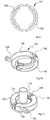
- Fig. 1 a tank is shown wherein instruments 2a and connection tubes 2b have been connected to the tank at the openings thereof 1 by means of coupling devices 3 according to the invention.
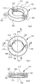
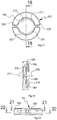
- Figs. 2 - 23 show a first embodiment of a coupling device 101 according to the invention which comprises two tension loops 102, a lock in the form of a nut and bolt joint 103, a hinge 104 and a spring 105 which is mounted at the hinge.
- the tension loops 102 which are moveable substantially in one level are designed with inner recesses 106 and in connection to the recesses provided, bevelled, inner loop surfaces 107 and 108.
- a bolt portion of the nut and bolt joint 103 is pivotally fastened at 112 to one of the tension loops 102 and the whole nut and bolt joint 103 is led through a hole in the other tension loop 102, in which the nut head abuts a shoulder (not shown) in the nut hole.
- the bolt portion of the nut and bolt joint 103 can be tightened from the outside of the coupling device 101. This can suitably first take place manually and for final tightening a tool can be used as an Allen key or the like, so that the whole nut and bolt joint 103 will be situated inside the outer periphery of the coupling device.
- a bevelled surface 113 is provided at the opening against the centre hole 114 of the coupling device 101 to facilitate the introduction of a connection flange of a tube 115, a conduit or the like.
- the surfaces 107 and 108 which borders the recesses 106 are bevelled radially outwardly in a direction towards the recesses 106 to thereby provide tightening surfaces for in the coupling device 101 received connection flanges 118 and 121, respectively, of a tank connection 120 and a tube connection 119, respectively (see Figs. 11 - 15 ).
- a gasket 122 is placed in a known manner between the connection flanges 118, 121 and is formed to fit in intended recesses.
- by providing the radially inner edges 110 and 111 of the loop surfaces 107 and 108, respectively, on different distances from the centre line 109 see also Fig.
- connection flanges 119 of the tube 121 can be hold in the recess 106 after it is placed in the recess 106 and the lock 103 is tightened to a certain position where it still can be moved apart against the bias of the spring 105 either manually or by pressing the connection flanges 121 of the tube 119 towards the bevelled surfaces 113 on the tension loops 102.
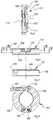
- Figs. 16 - 21 show a second embodiment of a coupling device 201 according to the invention, which comprises two tension loops 202 and two locks in the form of nut and bolt joints 203 and 204.
- the tension loops 202 which are moveable substantially in one level are designed with inner recesses 205 and in connection to he recesses 205 provided, bevelled, inner loop surfaces 206 and 207.
- Both nut and bolt joints 203, 204 are led through holes in one of the tension loops 202 and are screwed into holes in the other tension loop 202.
- the nut and bolt joints 203, 204 can be tightened from the outside of the coupling device 201. This can suitably first take place manually and for final tightening a tool can be used as an Allen key or the like, so that the whole nut and bolt joints 203, 204 will be situated inside the outer periphery of the coupling device.
- the surfaces 206 and 207 which border the recesses 205 are bevelled radially outwardly in the direction towards the recess 205 to thereby provide tension surfaces for in the coupling device 201 received, here not shown tension flanges of for instance a tank connection and a tube connection, respectively.
- tension flanges of for instance a tank connection and a tube connection, respectively.
- a not shown gasket is placed in a known manner between the connection flanges and is formed to fit in intended recesses.
- a bevelled surface 211 is provided at the opening against the centre hole 212 of the coupling device 201 to facilitate the introduction of the connection flange of the tube, a conduit or the like.
- a bevelled surface 211 is provided at the opening against the centre hole 212 of the coupling device 201 to facilitate the introduction of a connection flange of a tube, a conduit or the like.
- spring means can be placed in the hole of the nut and bolt joints to press the tension loops towards each other when the coupling is open.
- the locks in the form of the nut and bolt joints 203, 204 have been tightened to a certain position in which the tension loops 202 can be moved apart other manually or by pressing the connection flanges of the tube against the bevelled surfaces 211 on the tension loops 202.
- the invention can be varied in several different ways within the scope of the appended claims even if the above described embodiments are to prefer.
- the spring means at both above shown embodiments can be omitted or mounted in another way than what is described above.
- clamping devices or other tightening means can be used instead of the shown nut and bolt joints which constitute of bolts with over the bolts threaded elongated barrel nuts.
- clamping devices or other tightening means can be used.
- a position can be provided in which one of the connection flanges is received inside one of the loop surfaces of the inner edges of the tension loops, which loop surfaces are situated closest to the centre axis of the coupling device, so that the coupling device can be kept in place on one of the connection flanges at demounting as well as mounting of the other connection flange.
Landscapes
- Engineering & Computer Science (AREA)
- General Engineering & Computer Science (AREA)
- Mechanical Engineering (AREA)
- Flanged Joints, Insulating Joints, And Other Joints (AREA)
- Mutual Connection Of Rods And Tubes (AREA)
- Quick-Acting Or Multi-Walled Pipe Joints (AREA)
- Clamps And Clips (AREA)
Priority Applications (3)
| Application Number | Priority Date | Filing Date | Title |
|---|---|---|---|
| SI200831922T SI2137446T1 (en) | 2007-04-16 | 2008-04-14 | An assembly comprising a coupling device and two connecting flanges |
| PL08741909T PL2137446T3 (pl) | 2007-04-16 | 2008-04-14 | Układ zawierający urządzenie łączące i dwa kołnierze połączeniowe |
| HRP20180149TT HRP20180149T1 (hr) | 2007-04-16 | 2008-04-14 | Sklop koji obuhvaća spojni uređaj i dvije spojne prirubnice |
Applications Claiming Priority (3)
| Application Number | Priority Date | Filing Date | Title |
|---|---|---|---|
| SE0700942A SE531066C2 (sv) | 2007-04-16 | 2007-04-16 | Kopplingsanordning |
| US11/829,473 US7578530B2 (en) | 2007-04-16 | 2007-07-27 | Coupling device |
| PCT/SE2008/050419 WO2008127190A1 (en) | 2007-04-16 | 2008-04-14 | Coupling device |
Publications (3)
| Publication Number | Publication Date |
|---|---|
| EP2137446A1 EP2137446A1 (en) | 2009-12-30 |
| EP2137446A4 EP2137446A4 (en) | 2014-04-02 |
| EP2137446B1 true EP2137446B1 (en) | 2017-11-15 |
Family
ID=39853039
Family Applications (1)
| Application Number | Title | Priority Date | Filing Date |
|---|---|---|---|
| EP08741909.9A Active EP2137446B1 (en) | 2007-04-16 | 2008-04-14 | Arrangement comprising a coupling device and two connecting flanges |
Country Status (15)
| Country | Link |
|---|---|
| US (1) | US7578530B2 (enExample) |
| EP (1) | EP2137446B1 (enExample) |
| JP (1) | JP5276090B2 (enExample) |
| CY (1) | CY1119884T1 (enExample) |
| DK (1) | DK2137446T3 (enExample) |
| ES (1) | ES2659687T3 (enExample) |
| HR (1) | HRP20180149T1 (enExample) |
| HU (1) | HUE038144T2 (enExample) |
| LT (1) | LT2137446T (enExample) |
| NO (1) | NO2137446T3 (enExample) |
| PL (1) | PL2137446T3 (enExample) |
| PT (1) | PT2137446T (enExample) |
| SE (1) | SE531066C2 (enExample) |
| SI (1) | SI2137446T1 (enExample) |
| WO (1) | WO2008127190A1 (enExample) |
Families Citing this family (7)
| Publication number | Priority date | Publication date | Assignee | Title |
|---|---|---|---|---|
| US20120112026A1 (en) * | 2010-11-10 | 2012-05-10 | Kimball Physics, Inc. | Apparatus for supporting an assembly of conflat-connected ultra-high vacuum modules |
| US9915386B2 (en) * | 2013-08-14 | 2018-03-13 | Ho Young Lee | Clamp for pipe |
| US9228683B2 (en) * | 2013-12-22 | 2016-01-05 | Saint-Gobain Performance Plastics Corporation | Flanged tube apparatus |
| US11143336B1 (en) * | 2017-11-13 | 2021-10-12 | Tbl Performance Plastics, Llc | Connector, method of making connector and tubing assembly method |
| US10988298B2 (en) * | 2018-06-15 | 2021-04-27 | Cdf Corporation | Container assembly for flowable materials |
| DE102019005004A1 (de) * | 2019-07-17 | 2021-01-21 | Pharmatec GmbH | Vorrichtung und Verfahren zur Stabilisierung von elastomeren Kompensatoren während der Sterilisierungsphase |
| US11965613B2 (en) * | 2020-10-27 | 2024-04-23 | Zeta Gmbh | System and a method for providing a sterile fluid connection between a first fluid channel and a second fluid channel |
Citations (2)
| Publication number | Priority date | Publication date | Assignee | Title |
|---|---|---|---|---|
| JPS5925787U (ja) * | 1982-08-11 | 1984-02-17 | 高砂熱学工業株式会社 | 配管の可撓接続装置 |
| JP2004092700A (ja) * | 2002-08-29 | 2004-03-25 | Daido Tokushu Kogyo Kk | 食品医薬品用樹脂継手 |
Family Cites Families (22)
| Publication number | Priority date | Publication date | Assignee | Title |
|---|---|---|---|---|
| US2536602A (en) * | 1944-07-06 | 1951-01-02 | John J Goett | Automatic flange system |
| US3298698A (en) * | 1964-04-27 | 1967-01-17 | Owens Illinois Glass Co | Pipe coupling for joining pipe sections of varying size |
| GB1324981A (en) * | 1969-05-08 | 1973-07-25 | British Ropes Ltd | Couplings for pipes or the like |
| US3680894A (en) * | 1970-10-30 | 1972-08-01 | Victaulic Co Of America | Joints between pipes of different diameters and couplings and gaskets for the same |
| US3964774A (en) * | 1975-03-14 | 1976-06-22 | Ireco Industries, Inc. | Irrigation line coupler |
| US3977705A (en) * | 1975-08-20 | 1976-08-31 | Aeroquip Corporation | Reducing type coupling |
| JPS5925786U (ja) * | 1982-08-11 | 1984-02-17 | 高砂熱学工業株式会社 | 配管路における異径管の可撓接続装置 |
| FR2578593B1 (fr) * | 1985-03-08 | 1987-04-17 | Commissariat Energie Atomique | Collier de serrage telemanipulable |
| US4702499A (en) * | 1986-10-21 | 1987-10-27 | Victaulic Company Of America | Hingeable segmented pipe couplings |
| US4822077A (en) * | 1988-09-26 | 1989-04-18 | Urdan Industries (Usa) Inc. | Pipe coupling reducing insert |
| JPH09196261A (ja) * | 1996-01-12 | 1997-07-29 | Nkk Corp | 管継手構造 |
| US6056332A (en) * | 1999-03-09 | 2000-05-02 | Foster; Clark | Clamping apparatus |
| DE19950619C1 (de) * | 1999-10-20 | 2000-11-23 | Karl Weinhold | Rohrkupplung mit Schnellverschluß und Rohrflansch zur Verwendung mit einer solchen Rohrkupplung |
| JP2001248772A (ja) * | 2000-03-02 | 2001-09-14 | Advance Denki Kogyo Kk | チューブ類の接続構造 |
| US6834892B2 (en) * | 2001-12-20 | 2004-12-28 | Delaware Capital Formation, Inc. | Self-aligning coupling assembly |
| US6764284B2 (en) * | 2002-01-10 | 2004-07-20 | Parker-Hannifin Corporation | Pump mount using sanitary flange clamp |
| JP3923036B2 (ja) * | 2002-11-20 | 2007-05-30 | 東邦瓦斯株式会社 | 管継手構造 |
| US7086131B2 (en) * | 2004-05-14 | 2006-08-08 | Victaulic Company | Deformable mechanical pipe coupling |
| JP2006064144A (ja) * | 2004-08-30 | 2006-03-09 | Calsonic Kansei Corp | パイプの接続部構造 |
| JP2007092980A (ja) * | 2005-09-27 | 2007-04-12 | Tsunoda:Kk | 配管系フランジ継ぎ手のクランプ装置 |
| US7290805B2 (en) * | 2005-12-19 | 2007-11-06 | Highlight Tech. Corp. | Pipe clip |
| EP2442531A1 (en) | 2010-10-12 | 2012-04-18 | Thomson Licensing | Transmitting information |
-
2007
- 2007-04-16 SE SE0700942A patent/SE531066C2/sv unknown
- 2007-07-27 US US11/829,473 patent/US7578530B2/en active Active
-
2008
- 2008-04-14 LT LTEP08741909.9T patent/LT2137446T/lt unknown
- 2008-04-14 JP JP2010504014A patent/JP5276090B2/ja active Active
- 2008-04-14 EP EP08741909.9A patent/EP2137446B1/en active Active
- 2008-04-14 PL PL08741909T patent/PL2137446T3/pl unknown
- 2008-04-14 DK DK08741909.9T patent/DK2137446T3/en active
- 2008-04-14 ES ES08741909.9T patent/ES2659687T3/es active Active
- 2008-04-14 PT PT87419099T patent/PT2137446T/pt unknown
- 2008-04-14 HU HUE08741909A patent/HUE038144T2/hu unknown
- 2008-04-14 SI SI200831922T patent/SI2137446T1/en unknown
- 2008-04-14 HR HRP20180149TT patent/HRP20180149T1/hr unknown
- 2008-04-14 NO NO08741909A patent/NO2137446T3/no unknown
- 2008-04-14 WO PCT/SE2008/050419 patent/WO2008127190A1/en not_active Ceased
-
2018
- 2018-02-01 CY CY20181100124T patent/CY1119884T1/el unknown
Patent Citations (2)
| Publication number | Priority date | Publication date | Assignee | Title |
|---|---|---|---|---|
| JPS5925787U (ja) * | 1982-08-11 | 1984-02-17 | 高砂熱学工業株式会社 | 配管の可撓接続装置 |
| JP2004092700A (ja) * | 2002-08-29 | 2004-03-25 | Daido Tokushu Kogyo Kk | 食品医薬品用樹脂継手 |
Also Published As
| Publication number | Publication date |
|---|---|
| US7578530B2 (en) | 2009-08-25 |
| NO2137446T3 (enExample) | 2018-04-14 |
| SE531066C2 (sv) | 2008-12-09 |
| SE0700942L (sv) | 2008-10-17 |
| DK2137446T3 (en) | 2018-01-22 |
| EP2137446A4 (en) | 2014-04-02 |
| EP2137446A1 (en) | 2009-12-30 |
| SI2137446T1 (en) | 2018-06-29 |
| HRP20180149T1 (hr) | 2018-03-09 |
| JP2010525253A (ja) | 2010-07-22 |
| PT2137446T (pt) | 2018-02-06 |
| ES2659687T3 (es) | 2018-03-16 |
| US20080252075A1 (en) | 2008-10-16 |
| CY1119884T1 (el) | 2018-06-27 |
| WO2008127190A1 (en) | 2008-10-23 |
| LT2137446T (lt) | 2018-02-26 |
| HUE038144T2 (hu) | 2018-09-28 |
| PL2137446T3 (pl) | 2018-04-30 |
| JP5276090B2 (ja) | 2013-08-28 |
Similar Documents
| Publication | Publication Date | Title |
|---|---|---|
| EP2137446B1 (en) | Arrangement comprising a coupling device and two connecting flanges | |
| US8240718B2 (en) | Sanitary quick connector | |
| US7591489B2 (en) | Detachable pipe joint | |
| US10408371B2 (en) | Cam lever clamp for sanitary fittings | |
| US4316624A (en) | Access union | |
| US11703171B2 (en) | Cam-lever clamp | |
| US20080203723A1 (en) | Detachable pipe joint and joining method | |
| US20050258648A1 (en) | Clamp assembly for joining two annular ferrules | |
| JP2010255701A (ja) | 配管用クランプ継手 | |
| JP7381450B2 (ja) | 管継手とバルブ継手部のロック装置 | |
| CA1303094C (en) | Pipe union assembly | |
| JP5405253B2 (ja) | 配管用クランプ継手 | |
| JP5718779B2 (ja) | フェルール継手、フェルール継手の接続構造およびフェルール継手の接続方法 | |
| WO2008014363A2 (en) | Sanitary quick connector | |
| CA2628021A1 (en) | Pipe collar or clamp | |
| KR20140011734A (ko) | 유체이송용 커플러 | |
| KR101796002B1 (ko) | 진공배관용 클램프 | |
| KR200398123Y1 (ko) | 호스에 연결된 파이프 이음연결용 체결장치 | |
| JPH026398B2 (enExample) | ||
| US11460130B2 (en) | Easy to manoeuvre fluidic connector | |
| JP3226510U (ja) | 高圧配管用継手 | |
| US20250334214A1 (en) | Closure adapter | |
| JPH11193893A (ja) | バンジョウ型継手に用いられるバンジョウ部材のためのプロテクトキャップ及びプロテクトキャップを装着したバンジョウ型継手付ホース | |
| KR20150012924A (ko) | 가스필터 유니트의 개폐구 | |
| WO2025199389A1 (en) | Quick connect mounting assembly for use with hot melt applicator solenoid valve |
Legal Events
| Date | Code | Title | Description |
|---|---|---|---|
| PUAI | Public reference made under article 153(3) epc to a published international application that has entered the european phase |
Free format text: ORIGINAL CODE: 0009012 |
|
| 17P | Request for examination filed |
Effective date: 20091012 |
|
| AK | Designated contracting states |
Kind code of ref document: A1 Designated state(s): AT BE BG CH CY CZ DE DK EE ES FI FR GB GR HR HU IE IS IT LI LT LU LV MC MT NL NO PL PT RO SE SI SK TR |
|
| DAX | Request for extension of the european patent (deleted) | ||
| A4 | Supplementary search report drawn up and despatched |
Effective date: 20140304 |
|
| RIC1 | Information provided on ipc code assigned before grant |
Ipc: F16L 23/08 20060101ALI20140226BHEP Ipc: F16L 37/12 20060101AFI20140226BHEP Ipc: F16J 13/06 20060101ALI20140226BHEP Ipc: F16L 37/127 20060101ALI20140226BHEP Ipc: F16L 23/10 20060101ALI20140226BHEP |
|
| 17Q | First examination report despatched |
Effective date: 20160322 |
|
| GRAP | Despatch of communication of intention to grant a patent |
Free format text: ORIGINAL CODE: EPIDOSNIGR1 |
|
| INTG | Intention to grant announced |
Effective date: 20170612 |
|
| GRAS | Grant fee paid |
Free format text: ORIGINAL CODE: EPIDOSNIGR3 |
|
| GRAA | (expected) grant |
Free format text: ORIGINAL CODE: 0009210 |
|
| AK | Designated contracting states |
Kind code of ref document: B1 Designated state(s): AT BE BG CH CY CZ DE DK EE ES FI FR GB GR HR HU IE IS IT LI LT LU LV MC MT NL NO PL PT RO SE SI SK TR |
|
| REG | Reference to a national code |
Ref country code: AT Ref legal event code: REF Ref document number: 946635 Country of ref document: AT Kind code of ref document: T Effective date: 20171115 Ref country code: GB Ref legal event code: FG4D Ref country code: CH Ref legal event code: EP |
|
| REG | Reference to a national code |
Ref country code: IE Ref legal event code: FG4D |
|
| REG | Reference to a national code |
Ref country code: DE Ref legal event code: R096 Ref document number: 602008052976 Country of ref document: DE |
|
| REG | Reference to a national code |
Ref country code: DK Ref legal event code: T3 Effective date: 20180117 |
|
| REG | Reference to a national code |
Ref country code: HR Ref legal event code: TUEP Ref document number: P20180149 Country of ref document: HR |
|
| REG | Reference to a national code |
Ref country code: PT Ref legal event code: SC4A Ref document number: 2137446 Country of ref document: PT Date of ref document: 20180206 Kind code of ref document: T Free format text: AVAILABILITY OF NATIONAL TRANSLATION Effective date: 20180130 |
|
| REG | Reference to a national code |
Ref country code: NL Ref legal event code: FP Ref country code: RO Ref legal event code: EPE |
|
| REG | Reference to a national code |
Ref country code: HR Ref legal event code: T1PR Ref document number: P20180149 Country of ref document: HR |
|
| REG | Reference to a national code |
Ref country code: ES Ref legal event code: FG2A Ref document number: 2659687 Country of ref document: ES Kind code of ref document: T3 Effective date: 20180316 |
|
| REG | Reference to a national code |
Ref country code: FR Ref legal event code: PLFP Year of fee payment: 11 Ref country code: EE Ref legal event code: FG4A Ref document number: E015118 Country of ref document: EE Effective date: 20180202 |
|
| PG25 | Lapsed in a contracting state [announced via postgrant information from national office to epo] |
Ref country code: SE Free format text: LAPSE BECAUSE OF FAILURE TO SUBMIT A TRANSLATION OF THE DESCRIPTION OR TO PAY THE FEE WITHIN THE PRESCRIBED TIME-LIMIT Effective date: 20171115 |
|
| REG | Reference to a national code |
Ref country code: NO Ref legal event code: T2 Effective date: 20171115 |
|
| REG | Reference to a national code |
Ref country code: SK Ref legal event code: T3 Ref document number: E 26610 Country of ref document: SK |
|
| REG | Reference to a national code |
Ref country code: GR Ref legal event code: EP Ref document number: 20180400320 Country of ref document: GR Effective date: 20180627 |
|
| REG | Reference to a national code |
Ref country code: DE Ref legal event code: R097 Ref document number: 602008052976 Country of ref document: DE |
|
| PLBE | No opposition filed within time limit |
Free format text: ORIGINAL CODE: 0009261 |
|
| STAA | Information on the status of an ep patent application or granted ep patent |
Free format text: STATUS: NO OPPOSITION FILED WITHIN TIME LIMIT |
|
| REG | Reference to a national code |
Ref country code: HU Ref legal event code: AG4A Ref document number: E038144 Country of ref document: HU |
|
| 26N | No opposition filed |
Effective date: 20180817 |
|
| REG | Reference to a national code |
Ref country code: HR Ref legal event code: ODRP Ref document number: P20180149 Country of ref document: HR Payment date: 20190315 Year of fee payment: 12 |
|
| REG | Reference to a national code |
Ref country code: HR Ref legal event code: ODRP Ref document number: P20180149 Country of ref document: HR Payment date: 20200317 Year of fee payment: 13 |
|
| REG | Reference to a national code |
Ref country code: HR Ref legal event code: ODRP Ref document number: P20180149 Country of ref document: HR Payment date: 20210317 Year of fee payment: 14 |
|
| REG | Reference to a national code |
Ref country code: AT Ref legal event code: UEP Ref document number: 946635 Country of ref document: AT Kind code of ref document: T Effective date: 20171115 |
|
| REG | Reference to a national code |
Ref country code: HR Ref legal event code: ODRP Ref document number: P20180149 Country of ref document: HR Payment date: 20220315 Year of fee payment: 15 |
|
| REG | Reference to a national code |
Ref country code: FR Ref legal event code: PLFP Year of fee payment: 16 |
|
| REG | Reference to a national code |
Ref country code: HR Ref legal event code: ODRP Ref document number: P20180149 Country of ref document: HR Payment date: 20230315 Year of fee payment: 16 |
|
| REG | Reference to a national code |
Ref country code: HR Ref legal event code: ODRP Ref document number: P20180149 Country of ref document: HR Payment date: 20240319 Year of fee payment: 17 |
|
| PGFP | Annual fee paid to national office [announced via postgrant information from national office to epo] |
Ref country code: CY Payment date: 20240320 Year of fee payment: 17 |
|
| PGFP | Annual fee paid to national office [announced via postgrant information from national office to epo] |
Ref country code: SI Payment date: 20250404 Year of fee payment: 18 |
|
| REG | Reference to a national code |
Ref country code: HR Ref legal event code: ODRP Ref document number: P20180149 Country of ref document: HR Payment date: 20250407 Year of fee payment: 18 |
|
| PGFP | Annual fee paid to national office [announced via postgrant information from national office to epo] |
Ref country code: NL Payment date: 20250416 Year of fee payment: 18 |
|
| PGFP | Annual fee paid to national office [announced via postgrant information from national office to epo] |
Ref country code: LU Payment date: 20250416 Year of fee payment: 18 |
|
| PGFP | Annual fee paid to national office [announced via postgrant information from national office to epo] |
Ref country code: MC Payment date: 20250422 Year of fee payment: 18 |
|
| PGFP | Annual fee paid to national office [announced via postgrant information from national office to epo] |
Ref country code: FI Payment date: 20250422 Year of fee payment: 18 |
|
| PGFP | Annual fee paid to national office [announced via postgrant information from national office to epo] |
Ref country code: PL Payment date: 20250408 Year of fee payment: 18 Ref country code: DE Payment date: 20250423 Year of fee payment: 18 |
|
| PGFP | Annual fee paid to national office [announced via postgrant information from national office to epo] |
Ref country code: GB Payment date: 20250422 Year of fee payment: 18 Ref country code: ES Payment date: 20250512 Year of fee payment: 18 Ref country code: DK Payment date: 20250422 Year of fee payment: 18 |
|
| PGFP | Annual fee paid to national office [announced via postgrant information from national office to epo] |
Ref country code: LT Payment date: 20250407 Year of fee payment: 18 |
|
| PGFP | Annual fee paid to national office [announced via postgrant information from national office to epo] |
Ref country code: IS Payment date: 20250423 Year of fee payment: 18 Ref country code: HU Payment date: 20250509 Year of fee payment: 18 Ref country code: NO Payment date: 20250424 Year of fee payment: 18 |
|
| PGFP | Annual fee paid to national office [announced via postgrant information from national office to epo] |
Ref country code: BE Payment date: 20250416 Year of fee payment: 18 Ref country code: IT Payment date: 20250418 Year of fee payment: 18 |
|
| PGFP | Annual fee paid to national office [announced via postgrant information from national office to epo] |
Ref country code: HR Payment date: 20250407 Year of fee payment: 18 |
|
| PGFP | Annual fee paid to national office [announced via postgrant information from national office to epo] |
Ref country code: PT Payment date: 20250404 Year of fee payment: 18 Ref country code: LV Payment date: 20250423 Year of fee payment: 18 |
|
| PGFP | Annual fee paid to national office [announced via postgrant information from national office to epo] |
Ref country code: FR Payment date: 20250417 Year of fee payment: 18 Ref country code: EE Payment date: 20250501 Year of fee payment: 18 |
|
| PGFP | Annual fee paid to national office [announced via postgrant information from national office to epo] |
Ref country code: MT Payment date: 20250417 Year of fee payment: 18 Ref country code: BG Payment date: 20250423 Year of fee payment: 18 Ref country code: GR Payment date: 20250423 Year of fee payment: 18 |
|
| PGFP | Annual fee paid to national office [announced via postgrant information from national office to epo] |
Ref country code: CH Payment date: 20250501 Year of fee payment: 18 |
|
| PGFP | Annual fee paid to national office [announced via postgrant information from national office to epo] |
Ref country code: AT Payment date: 20250424 Year of fee payment: 18 Ref country code: RO Payment date: 20250409 Year of fee payment: 18 |
|
| PGFP | Annual fee paid to national office [announced via postgrant information from national office to epo] |
Ref country code: SK Payment date: 20250404 Year of fee payment: 18 Ref country code: TR Payment date: 20250404 Year of fee payment: 18 |
|
| PGFP | Annual fee paid to national office [announced via postgrant information from national office to epo] |
Ref country code: CZ Payment date: 20250404 Year of fee payment: 18 |
|
| PGFP | Annual fee paid to national office [announced via postgrant information from national office to epo] |
Ref country code: IE Payment date: 20250417 Year of fee payment: 18 |