EP2137397B1 - Verbrennungsluft- und abgasanordnung eines verbrennungsmotors - Google Patents
Verbrennungsluft- und abgasanordnung eines verbrennungsmotors Download PDFInfo
- Publication number
- EP2137397B1 EP2137397B1 EP08736536A EP08736536A EP2137397B1 EP 2137397 B1 EP2137397 B1 EP 2137397B1 EP 08736536 A EP08736536 A EP 08736536A EP 08736536 A EP08736536 A EP 08736536A EP 2137397 B1 EP2137397 B1 EP 2137397B1
- Authority
- EP
- European Patent Office
- Prior art keywords
- swirl generator
- exhaust
- exhaust gas
- flow
- swirl
- Prior art date
- Legal status (The legal status is an assumption and is not a legal conclusion. Google has not performed a legal analysis and makes no representation as to the accuracy of the status listed.)
- Not-in-force
Links
Images
Classifications
-
- F—MECHANICAL ENGINEERING; LIGHTING; HEATING; WEAPONS; BLASTING
- F02—COMBUSTION ENGINES; HOT-GAS OR COMBUSTION-PRODUCT ENGINE PLANTS
- F02M—SUPPLYING COMBUSTION ENGINES IN GENERAL WITH COMBUSTIBLE MIXTURES OR CONSTITUENTS THEREOF
- F02M35/00—Combustion-air cleaners, air intakes, intake silencers, or induction systems specially adapted for, or arranged on, internal-combustion engines
- F02M35/10—Air intakes; Induction systems
- F02M35/1015—Air intakes; Induction systems characterised by the engine type
- F02M35/10157—Supercharged engines
-
- B—PERFORMING OPERATIONS; TRANSPORTING
- B01—PHYSICAL OR CHEMICAL PROCESSES OR APPARATUS IN GENERAL
- B01D—SEPARATION
- B01D45/00—Separating dispersed particles from gases or vapours by gravity, inertia, or centrifugal forces
- B01D45/12—Separating dispersed particles from gases or vapours by gravity, inertia, or centrifugal forces by centrifugal forces
-
- B—PERFORMING OPERATIONS; TRANSPORTING
- B01—PHYSICAL OR CHEMICAL PROCESSES OR APPARATUS IN GENERAL
- B01D—SEPARATION
- B01D46/00—Filters or filtering processes specially modified for separating dispersed particles from gases or vapours
- B01D46/10—Particle separators, e.g. dust precipitators, using filter plates, sheets or pads having plane surfaces
- B01D46/12—Particle separators, e.g. dust precipitators, using filter plates, sheets or pads having plane surfaces in multiple arrangements
-
- F—MECHANICAL ENGINEERING; LIGHTING; HEATING; WEAPONS; BLASTING
- F02—COMBUSTION ENGINES; HOT-GAS OR COMBUSTION-PRODUCT ENGINE PLANTS
- F02B—INTERNAL-COMBUSTION PISTON ENGINES; COMBUSTION ENGINES IN GENERAL
- F02B37/00—Engines characterised by provision of pumps driven at least for part of the time by exhaust
-
- F—MECHANICAL ENGINEERING; LIGHTING; HEATING; WEAPONS; BLASTING
- F02—COMBUSTION ENGINES; HOT-GAS OR COMBUSTION-PRODUCT ENGINE PLANTS
- F02M—SUPPLYING COMBUSTION ENGINES IN GENERAL WITH COMBUSTIBLE MIXTURES OR CONSTITUENTS THEREOF
- F02M26/00—Engine-pertinent apparatus for adding exhaust gases to combustion-air, main fuel or fuel-air mixture, e.g. by exhaust gas recirculation [EGR] systems
- F02M26/02—EGR systems specially adapted for supercharged engines
- F02M26/04—EGR systems specially adapted for supercharged engines with a single turbocharger
- F02M26/06—Low pressure loops, i.e. wherein recirculated exhaust gas is taken out from the exhaust downstream of the turbocharger turbine and reintroduced into the intake system upstream of the compressor
-
- F—MECHANICAL ENGINEERING; LIGHTING; HEATING; WEAPONS; BLASTING
- F02—COMBUSTION ENGINES; HOT-GAS OR COMBUSTION-PRODUCT ENGINE PLANTS
- F02M—SUPPLYING COMBUSTION ENGINES IN GENERAL WITH COMBUSTIBLE MIXTURES OR CONSTITUENTS THEREOF
- F02M26/00—Engine-pertinent apparatus for adding exhaust gases to combustion-air, main fuel or fuel-air mixture, e.g. by exhaust gas recirculation [EGR] systems
- F02M26/02—EGR systems specially adapted for supercharged engines
- F02M26/09—Constructional details, e.g. structural combinations of EGR systems and supercharger systems; Arrangement of the EGR and supercharger systems with respect to the engine
-
- F—MECHANICAL ENGINEERING; LIGHTING; HEATING; WEAPONS; BLASTING
- F02—COMBUSTION ENGINES; HOT-GAS OR COMBUSTION-PRODUCT ENGINE PLANTS
- F02M—SUPPLYING COMBUSTION ENGINES IN GENERAL WITH COMBUSTIBLE MIXTURES OR CONSTITUENTS THEREOF
- F02M26/00—Engine-pertinent apparatus for adding exhaust gases to combustion-air, main fuel or fuel-air mixture, e.g. by exhaust gas recirculation [EGR] systems
- F02M26/13—Arrangement or layout of EGR passages, e.g. in relation to specific engine parts or for incorporation of accessories
- F02M26/17—Arrangement or layout of EGR passages, e.g. in relation to specific engine parts or for incorporation of accessories in relation to the intake system
- F02M26/19—Means for improving the mixing of air and recirculated exhaust gases, e.g. venturis or multiple openings to the intake system
-
- F—MECHANICAL ENGINEERING; LIGHTING; HEATING; WEAPONS; BLASTING
- F02—COMBUSTION ENGINES; HOT-GAS OR COMBUSTION-PRODUCT ENGINE PLANTS
- F02M—SUPPLYING COMBUSTION ENGINES IN GENERAL WITH COMBUSTIBLE MIXTURES OR CONSTITUENTS THEREOF
- F02M26/00—Engine-pertinent apparatus for adding exhaust gases to combustion-air, main fuel or fuel-air mixture, e.g. by exhaust gas recirculation [EGR] systems
- F02M26/13—Arrangement or layout of EGR passages, e.g. in relation to specific engine parts or for incorporation of accessories
- F02M26/35—Arrangement or layout of EGR passages, e.g. in relation to specific engine parts or for incorporation of accessories with means for cleaning or treating the recirculated gases, e.g. catalysts, condensate traps, particle filters or heaters
-
- F—MECHANICAL ENGINEERING; LIGHTING; HEATING; WEAPONS; BLASTING
- F02—COMBUSTION ENGINES; HOT-GAS OR COMBUSTION-PRODUCT ENGINE PLANTS
- F02M—SUPPLYING COMBUSTION ENGINES IN GENERAL WITH COMBUSTIBLE MIXTURES OR CONSTITUENTS THEREOF
- F02M29/00—Apparatus for re-atomising condensed fuel or homogenising fuel-air mixture
- F02M29/04—Apparatus for re-atomising condensed fuel or homogenising fuel-air mixture having screens, gratings, baffles or the like
- F02M29/06—Apparatus for re-atomising condensed fuel or homogenising fuel-air mixture having screens, gratings, baffles or the like generating whirling motion of mixture
-
- F—MECHANICAL ENGINEERING; LIGHTING; HEATING; WEAPONS; BLASTING
- F02—COMBUSTION ENGINES; HOT-GAS OR COMBUSTION-PRODUCT ENGINE PLANTS
- F02M—SUPPLYING COMBUSTION ENGINES IN GENERAL WITH COMBUSTIBLE MIXTURES OR CONSTITUENTS THEREOF
- F02M35/00—Combustion-air cleaners, air intakes, intake silencers, or induction systems specially adapted for, or arranged on, internal-combustion engines
- F02M35/10—Air intakes; Induction systems
- F02M35/10006—Air intakes; Induction systems characterised by the position of elements of the air intake system in direction of the air intake flow, i.e. between ambient air inlet and supply to the combustion chamber
- F02M35/10026—Plenum chambers
- F02M35/10059—Swirl chamber upstream of the plenum chamber
-
- F—MECHANICAL ENGINEERING; LIGHTING; HEATING; WEAPONS; BLASTING
- F02—COMBUSTION ENGINES; HOT-GAS OR COMBUSTION-PRODUCT ENGINE PLANTS
- F02M—SUPPLYING COMBUSTION ENGINES IN GENERAL WITH COMBUSTIBLE MIXTURES OR CONSTITUENTS THEREOF
- F02M35/00—Combustion-air cleaners, air intakes, intake silencers, or induction systems specially adapted for, or arranged on, internal-combustion engines
- F02M35/10—Air intakes; Induction systems
- F02M35/10209—Fluid connections to the air intake system; their arrangement of pipes, valves or the like
- F02M35/10222—Exhaust gas recirculation [EGR]; Positive crankcase ventilation [PCV]; Additional air admission, lubricant or fuel vapour admission
-
- F—MECHANICAL ENGINEERING; LIGHTING; HEATING; WEAPONS; BLASTING
- F02—COMBUSTION ENGINES; HOT-GAS OR COMBUSTION-PRODUCT ENGINE PLANTS
- F02M—SUPPLYING COMBUSTION ENGINES IN GENERAL WITH COMBUSTIBLE MIXTURES OR CONSTITUENTS THEREOF
- F02M26/00—Engine-pertinent apparatus for adding exhaust gases to combustion-air, main fuel or fuel-air mixture, e.g. by exhaust gas recirculation [EGR] systems
- F02M26/13—Arrangement or layout of EGR passages, e.g. in relation to specific engine parts or for incorporation of accessories
- F02M26/22—Arrangement or layout of EGR passages, e.g. in relation to specific engine parts or for incorporation of accessories with coolers in the recirculation passage
- F02M26/23—Layout, e.g. schematics
-
- Y—GENERAL TAGGING OF NEW TECHNOLOGICAL DEVELOPMENTS; GENERAL TAGGING OF CROSS-SECTIONAL TECHNOLOGIES SPANNING OVER SEVERAL SECTIONS OF THE IPC; TECHNICAL SUBJECTS COVERED BY FORMER USPC CROSS-REFERENCE ART COLLECTIONS [XRACs] AND DIGESTS
- Y02—TECHNOLOGIES OR APPLICATIONS FOR MITIGATION OR ADAPTATION AGAINST CLIMATE CHANGE
- Y02T—CLIMATE CHANGE MITIGATION TECHNOLOGIES RELATED TO TRANSPORTATION
- Y02T10/00—Road transport of goods or passengers
- Y02T10/10—Internal combustion engine [ICE] based vehicles
- Y02T10/12—Improving ICE efficiencies
Definitions
- the invention relates to an arrangement for supplying an internal combustion engine, in particular of a motor vehicle, with a combustion air stream and for discharging an exhaust gas stream from the internal combustion engine having the features according to the preamble of claim 1.
- Performance, running behavior and exhaust emission of internal combustion engines, especially of motor vehicles, are largely influenced not only by the engine itself but also by its arrangement for supplying combustion air and for discharging the exhaust gas flow.
- exhaust gas turbochargers are widely used, which have a compressor arranged in the fresh air duct and a turbine arranged in the exhaust gas duct.
- an exhaust-gas turbocharger desirably generates a boost pressure increase of the combustion air flow and an associated increased power output.
- the compressor of the exhaust gas turbocharger Under partial load, it may be advantageous to flow the compressor of the exhaust gas turbocharger with a defined Vordrall.
- the compressor of the exhaust gas turbocharger upstream of a swirl generator the provides the incoming combustion air flow with a swirl.
- the operating characteristics of the exhaust gas turbocharger are improved under partial load.
- a known measure is to provide a low-pressure exhaust gas recirculation, with which an exhaust gas recirculation flow is introduced into the combustion air flow in the partial load range. This serves primarily to reduce pollutants, in particular the reduction of NOX emissions.
- the invention has the object of developing a generic combustion air and exhaust gas arrangement of an internal combustion engine such that the reliability of the exhaust gas turbocharger is improved.
- An arrangement is proposed for supplying an internal combustion engine with a combustion air flow and for discharging an exhaust gas flow, in which the swirl generator provided for the improved partial load operation is designed as a centrifugal separator for condensate formed in the exhaust gas recirculation flow.
- a peripheral portion of the swirl generator is provided with a radially outer separator for separated condensate.
- the condensate droplets which are forced radially outwards by the swirl, collect on the inside of the peripheral section and, under the action of the spin-induced centrifugal force, assisted by the supporting effect of the gas flow, enter the Abscheiderinne. Collection in the separation channel avoids reintroduction of the separated condensate into the gas stream and also allows for controlled discharge from the centrifugal separator.
- the separation channel advantageously extends in the circumferential direction of the swirl generator by at least 180 ° and in particular over approximately 270 °. This ensures that the separated condensate can be substantially completely collected and discharged.
- the cross section of the separator channels advantageously increases with the direction of rotation of the swirl generator.
- a condensate drainage channel is led out of the latter in an end region of the separation channel in relation to the direction of rotation of the swirl generator.
- the increasing amount of condensate in the direction of rotation can be reliably completely absorbed by the separator and derived using its kinetic energy occurring in the direction of rotation of the swirl generator on the condensate discharge channel.
- a radially outwardly inclined sealing lip is arranged on at least one longitudinal edge of the separator.
- the arrangement of separator and sealing lip acts as a trap for the separated condensate, which, although readily penetrate into the separator, but can not get back out of the gas flow back out of it.
- the swirl generator has a central, essentially rectilinear main air duct and a swirl air duct which opens into the main air duct with a tangential direction component, the return duct being guided into the swirl air duct.
- a secondary air flow introduced through the swirl air duct and also the exhaust gas recirculation flow can be adapted to the respective operating states of the internal combustion engine. For example, is dispensed with an exhaust gas recirculation in full load operation, the introduction of the secondary air flow can be reduced for generating swirl or even switched off.
- secondary air flow of the exhaust gas recirculation flow is introduced with high kinetic energy and provided with swirl, which occur without additional measures considerable inertial forces and thus a good separation efficiency.
- a heat exchanger which cools the exhaust gas recirculation flow is expediently arranged in the return duct.
- the exhaust gas turbocharger and the internal combustion engine are supplied with cool, enriched by recirculated exhaust gas combustion air, whereby the internal combustion engine with high power output can be operated with reduced pollutant emissions.
- the effect of the heat exchanger occurring increased tendency to form condensate the advantages of the arrangement according to the invention are particularly clear:
- the effective separation immediately on the input side of the compressor ensures that a substantially condensate-free gas stream enters the compressor, whereby this has an increased reliability.
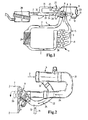
- FIG. 1 1 is a schematic block diagram of an internal combustion engine with an exhaust gas turbocharger, with a low-pressure exhaust gas recirculation and with a swirl generator designed as a centrifugal separator for improved engine part load operation;
- FIG. 2 a side view of a portion of the fresh air duct with the swirl generator after FIG. 1 .
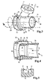
- FIG. 3 an enlarged perspective view of the swirl generator with integrated centrifugal after FIG. 2 .
- FIG. 4 a perspective longitudinal section of the swirl generator after FIG. 3 with details of the flow guidance and its effect on the separation and condensate drainage in a separation channel
- FIG. 5 a schematic, enlarged cross-sectional view of the separator according to FIG. 4 with arranged on longitudinal edges sealing lips.
- Fig. 1 shows a schematic block diagram of an internal combustion engine 1, which may be a diesel engine, a gasoline engine or the like.
- the internal combustion engine 1 is provided for driving a motor vehicle. It may also be a stationary engine or the like appropriate.
- the internal combustion engine 1 is provided with an arrangement according to the invention for supplying a combustion air stream 2 and for discharging an exhaust gas stream 3.
- the arrangement comprises a fresh air duct 4, an exhaust duct 5, an exhaust gas turbocharger 6 and a low-pressure exhaust gas recirculation 10 with a return duct 11.
- the exhaust stream 3 is collected from the engine 1 by means of an exhaust manifold 31 and discharged via the exhaust passage 5.
- the combustion air flow 2 for the combustion of the fuel in the internal combustion engine 1 is supplied through a fresh air duct 4 to the internal combustion engine 1. In this case, it passes on the input side through an air filter 28 arranged in the fresh air duct 4 and is fed to the individual cylinders of the internal combustion engine 1 by means of an intake manifold 30.
- the exhaust-gas turbocharger 6 has a compressor 7 arranged in the fresh-air duct 4 and a turbine 8 arranged in the exhaust-gas duct 5, the turbine 8 driven by the combustion-air flow 2 guided in the exhaust duct 5 in turn driving the compressor 7.
- the compressor 7 increases the boost pressure of the passed through the air filter 28 combustion air stream 2.
- a charge air cooler 29 is disposed between the compressor 7 and the intake manifold 30.
- an exhaust gas recirculation flow 12 is branched off from the exhaust gas flow 3 and admixed to the combustion air flow 2 upstream of the exhaust gas turbocharger 6 in certain operating states of the internal combustion engine 1, in particular at partial load.
- the internal combustion engine 1 is operated with swirling Ver emphasizeranströmung.Hierzu a swirl generator 9 is arranged in the fresh air duct 4, which is connected upstream of the compressor 7 immediately on the input side.
- the swirl generator 9 provides in the manner described in more detail below the entering into the compressor 7 Verrennungs Kunststoffstrom 2 with a twist.
- the swirl generator 9 is also formed in a manner also described in more detail below as a centrifugal separator 13 for in the exhaust gas recirculation flow 12 forming condensate.
- the condensate is separated in the centrifugal separator 13 and discharged according to an arrow 43 from the swirl generator 9 and can be collected, further treated or returned to the engine.
- the incoming combustion air stream 2 is provided, for example via aerodynamic vanes or the like with a twist, whereby the response of the exhaust gas turbocharger 6 is improved.
- This swirl also acts on the upstream exhaust gas recirculation flow 12, which produces the separation effect described below.
- the fresh air duct 4 between the air filter 28 and the compressor 7, a branch 32, downstream of the branch 32, a main air duct 21 and a swirl air duct 22 are connected in parallel flow-conducting.
- a control device 26, 27 is optionally arranged, by means of which a main air flow 24 in the main air duct 21 and a secondary air flow 25 in the swirl air duct 22 can be controlled or regulated amount.
- the swirl air channel 22 opens into the Swirl generator 9, wherein the secondary air stream 25 are combined with the main air stream 24 immediately upstream of the compressor 7 with each other. Via the secondary air flow 25, a swirl is generated in a manner to be described in more detail below which acts not only proportionally on the secondary air flow 25 but also on the main air flow 24, as a result of which the exhaust gas turbocharger 6 operates with swirl assistance. As a result, the operating characteristics of the exhaust turbocharger are improved under partial load and low engine speed.
- the exhaust gas turbocharger 6 is fed at least primarily with substantially swirl-free combustion air from the main air stream 24, which in turn can be controlled or regulated by means of the control device 26.
- the return duct 11 opens into the swirl air duct 22 downstream of the associated control device 27 and upstream of the swirl generator 9. Upstream of the swirl generator 9, a heat exchanger 23 which cools the exhaust gas recirculation flow 12 is arranged in the return duct 11. Depending on the position of the control device 27, more or less combustion air in the form of the secondary air flow 25 is added to the exhaust gas recirculation flow 12. The mixture of the secondary air stream 25 and the exhaust gas recirculation flow 12, possibly also the exhaust gas recirculation flow 12 alone, is obtained in the swirl generator 9 a twist.
- Fig. 2 shows a side view of a section of the fresh air duct 4 after Fig. 1 in the region of the main air channel 21, the swirl air duct 22 and the swirl generator 9.
- the swirl generator 9 is flanged directly on the input side of the indicated compressor 7 on the end face.
- the main air channel 21 with the main air stream 24 discharges substantially rectilinearly into the compressor 7.
- the swirl air channel 22 is part of the fresh air channel 4 and branches off the secondary air stream 25 at the branch 32 from the combustion air stream 2.
- the indicated return channel 11 opens upstream of the swirl generator 9 in the swirl air duct 22, where the exhaust gas recirculation flow 12 is mixed with the secondary air stream 25.
- This mixture is introduced into the swirl generator 9 substantially tangentially with an axial direction component and thus experiences a swirl with a direction of rotation, which is indicated here by an arrow 33.
- This twist also transfers to the central main air flow 24.
- the introduction of the exhaust gas recirculation flow 12 takes place in the same direction of rotation as the air flow in the swirl generator.
- the swirl generator 9 comprises a central, approximately cylindrical pipe socket 34 with a longitudinal axis 38. From the synopsis with Fig. 2 shows that the substantially rectilinear pipe socket 34 is part of the central main air channel 21, through which the main air stream 24 is passed in a straight line and axially parallel to the longitudinal axis 38 according to an arrow 37.
- the swirl air channel 22 opens tangentially and inclined to the longitudinal axis 38 in the swirl generator 9, wherein the swirl air channel 22 is guided with a tangential and with an axial direction component in the main air channel 21.
- This introduction takes place via a spiral section 35 which is guided around the pipe socket 34 on the outside, in which the gas stream of the swirl air channel 22 entering in accordance with an arrow 36 with a tangential and axial direction component experiences a twist.
- the various gas streams mix according to the arrows 36, 37, 39 to a Total gas flow with swirl and axial direction component corresponding to an arrow 40.
- the swirl generator 9 in the region of its spiral section 35 a peripheral portion 15 in the form of a peripheral wall, in the radially outermost periphery an inwardly open separator channel 16 is formed for separated condensate.
- the separation channel 16 Based on the inflow of the gas according to the arrow 36, the separation channel 16 extends in the circumferential direction of the swirl generator 9 over at least 180 °. In the embodiment shown, it extends according to the arrow 39 about 270 ° about the longitudinal axis 38 around.
- the separation channel 16 Based on the rotation direction of the air flow in the swirl generator 9 indicated by the arrow 40, the separation channel 16 has an end region 20 lying in the direction of the direction of rotation 40.
- There is a condensate drainage channel 19 is provided, which is led out in this end portion 20 of the separation channel 16 and the according to the illustration Fig. 1 deposited condensate according to the arrow 43 shown there.
- Fig. 4 shows a longitudinal sectional view of the swirl generator 9 after Fig. 3 ,
- the provided for forming the centrifugal separator 13 peripheral portion 15 of the spiral portion 35 encloses a longitudinally extending partially in the cylindrical inner wall 41 of the pipe socket 34, but according to an arrow 42 a flow-conducting connection between the spiral portion 35 and the pipe socket 34 is made.
- the main air flow 24 ( Fig.
- FIG. 4 shows as shown Fig. 4 a main flow direction 14.
- Fig. 3 shows inclination of the swirl air duct 22 to the longitudinal axis 38 of the main air channel 21 and the narrowing cross-sectional shape of the spiral section 35 cause an introduction of the exhaust gas recirculation flow 12 together with the secondary air stream 25 (FIGS. Fig. 2 ) not only substantially tangentially, but also with an axial direction component parallel to the main flow direction 14 of the swirl generator 9 in the swirl generator 9 in accordance with the arrow 42 ( Fig. 4 ) he follows.
- FIG. 5 Further details on the design of the separator 16 are the schematic cross-sectional view Fig. 5 refer to.
- the molded into the peripheral portion 15 Abscheiderinne 16 is limited to its open side by longitudinal edges 17.
- On both longitudinal edges 17 schematically indicated sealing lips 18 are arranged, which converge in the cross-sectional view shown starting from the longitudinal edges 17 and are slightly inclined radially outwardly, ie in the direction of the bottom of the separation channel 16.
- separated condensate may indeed enter into the separation channel 16, but not or only with difficulty back into the spiral section 35 (FIG. Fig. 4 ) reach.
Landscapes
- Engineering & Computer Science (AREA)
- Chemical & Material Sciences (AREA)
- Combustion & Propulsion (AREA)
- Mechanical Engineering (AREA)
- General Engineering & Computer Science (AREA)
- Chemical Kinetics & Catalysis (AREA)
- Exhaust-Gas Circulating Devices (AREA)
- Supercharger (AREA)
Description
- Die Erfindung betrifft eine Anordnung zur Versorgung eines Verbrennungsmotors insbesondere eines Kraftfahrzeuges mit einem Verbrennungsluftstrom und zur Ableitung eines Abgasstromes von dem Verbrennungsmotor mit den Merkmalen nach dem Oberbegriff des Anspruchs 1.
- Leistung, Laufverhalten und Abgasemission von Verbrennungsmotoren, insbesondere von Kraftfahrzeugen, werden in weiten Teilen nicht nur vom Motor selbst, sondern auch von dessen Anordnung zur Versorgung mit Verbrennungsluft sowie zur Ableitung des Abgasstromes beeinflusst. Zur Leistungssteigerung werden verbreitet Abgasturbolader eingesetzt, die einen im Frischluftkanal angeordneten Verdichter und eine im Abgaskanal angeordnete Turbine aufweisen. Bei mittleren und hohen Leistungen des Verbrennungsmotors erzeugt ein derartiger Abgasturbolader in gewünschter Weise eine Ladedruckerhöhung des Verbrennungsluftstromes und eine damit einhergehende erhöhte Leistungsausbeute.
- Unter Teillast kann es vorteilhaft sein den Verdichter des Abgasturboladers mit einem definierten Vordrall anzuströmen. Dazu wird dem Verdichter des Abgasturboladers ein Drallerzeuger vorgeschaltet, der den eintretenden Verbrennungsluftstrom mit einem Drall versieht. Hierdurch werden die Betriebseigenschaften des Abgasturboladers unter Teillast verbessert.
- Unabhängig von der vorgenannten Problemstellung sind nach dem Stand der Technik verschiedene Maßnahmen vorgesehen, um die Abgasemission zu verbessern. Eine bekannte Maßnahme besteht darin, eine Niederdruckabgasrückführung vorzusehen, mit der im Teillastbereich ein Abgasrückführungsstrom in den Verbrennungsluftstrom eingeleitet wird. Dies dient in erster Linie der Schadstoffreduzierung, insbesondere der Reduzierung von NOX-Ausstoß.
- Über die Länge der Abgasrückführung kühlt sich der Abgasrückführungsstrom ab. Dies kann zur Kondensatbildung, insbesondere zur Bildung von Wassertröpfchen führen, die beim Auftreffen auf die hoch drehenden Verdichterschaufeln des Abgasturboladers den Verdichter beschädigen können. Zur Vermeidung dieses unerwünschten Effektes werden Kondensatabscheider eingesetzt, die im Abgasstrom gebildetes Kondensat zumindest teilweise abscheiden. Bau- und Kostenaufwand sind hoch. Dieser Abscheider befindet sich in vorbekannter Bauform in einem gewissen Abstand zum Verdichtereintritt, so dass bei Mischung des Abgasrückführungsstromes mit dem Verbrennungsluftstrom eine Nachkondensation mit wiederholter Tröpfchenbildung einsetzen kann. Aus der
WO 2006/045488 A1 ist die Anordnung eines Flichkraftabscheiders direkt vor dem Verdichter bekannt geworden. - Der Erfindung liegt die Aufgabe zugrunde, eine gattungsgemäße Verbrennungsluft- und Abgasanordnung eines Verbrennungsmotors derart weiterzubilden, dass die Betriebssicherheit des Abgasturboladers verbessert ist.
- Diese Aufgabe wird durch eine Anordnung mit den Merkmalen des Anspruchs 1 gelöst.
- Es wird eine Anordnung zur Versorgung eines Verbrennungsmotors mit einem Verbrennungsluftstrom und zur Ableitung eines Abgasstromes vorgeschlagen, bei welcher der für den verbesserten Teillastbetrieb vorgesehene Drallerzeuger als Zentrifugalabscheider für im Abgasrückführungsstrom gebildetes Kondensat ausgebildet ist.
- Durch Nutzung der im Drallerzeuger ohnehin auftretenden, auf gebildetes Kondensat wirkende Fliehkraft- bzw. Massenträgheitskräfte kann ohne Zusatzmaßnahmen eine wirkungsvolle Abscheidung herbeigeführt werden. Auf den Aufwand eines zusätzlichen Zentrifugalabscheiders kann verzichtet werden. Systembedingt ist der Drallerzeuger für den für seine Funktion unter Teillast unmittelbar am Verdichtereintritt angeordnet, so dass ein langer Mischweg und damit die Gefahr der wiederholten Tröpfchenbildung entfällt. Da der zusätzliche Abscheider entfällt, ist nur ein verringerter Bauraum erforderlich. Der Verbrennungsmotor kann samt seiner Anbauteile kompakter aufgebaut werden.
- Es kann zweckmäßig sein, den Abgasrückführungsstrom stromauf des Drallerzeugers mit dem Verbrennungsluftstrom zu mischen, wobei die Drallerzeugung bei gleichzeitiger Kondensatabscheidung erst im nachgeschalteten Drallerzeuger erfolgt.
Die Einleitung des Abgasrückführungsstromes ist im Wesentlichen tangential mit dem Drehsinn der Luftströmung im Drallerzeuger vorgesehen. Hierdurch wird die Strömungsgeschwindigkeit des Abgasrückführungsstromes im gemischten oder ungemischten Zustand direkt in einen Drall bei gleichzeitig sich einstellender Abscheidewirkung umgesetzt. Auf einen zusätzlichen Energieeintrag zur Drallerzeugung kann verzichtet werden. Zweckmäßig ist zusätzlich dazu eine Einleitung des Abgasrückführungsstromes mit einer axialen Richtungskomponente, d. h. in einem spitzen Winkel zur Hauptströmungsrichtung des Drallerzeugers in den Drallerzeuger vorgesehen. Die axiale Anströmgeschwindigkeit des Verdichters ist dadurch verbessert. - In einer zweckmäßigen Ausführung ist ein Umfangsabschnitt des Drallerzeugers mit einer radial außen liegenden Abscheiderinne für abgeschiedenes Kondensat versehen. Die durch den Drall radial nach außen gedrängten Kondensattröpfchen sammeln sich innenseitig des Umfangsabschnittes und treten dort unter Einwirkung der drallbedingten Fliehkraft, unterstützt durch die Tragwirkung des Gasstromes, in die Abscheiderinne. Die Sammlung in der Abscheiderinne vermeidet einen Wiedereintrag des abgeschiedenen Kondensats in den Gasstrom und lässt außerdem eine gesteuerte Ableitung aus dem Zentrifugalabscheider zu.
- Die Abscheiderinne erstreckt sich vorteilhaft in Umfangsrichtung des Drallerzeugers um mindestens 180° und insbesondere über etwa 270°. Hierdurch ist sichergestellt, dass das abgeschiedene Kondensat im Wesentlichen vollständig gesammelt und abgeleitet werden kann.
- Der Querschnitt der Abscheiderinne vergrößert sich vorteilhaft mit dem Drehsinn des Drallerzeugers. Insbesondere ist ein Kondensatableitungskanal bezogen auf den Drehsinn des Drallerzeugers in einem Endbereich der Abscheiderinne aus dieser herausgeführt. Das im Drehsinn zunehmende Kondensataufkommen kann zuverlässig vollständig von der Abscheiderinne aufgenommen und unter Nutzung seiner im Drehsinn des Drallerzeugers auftretenden Bewegungsenergie über den Kondensatableitungskanal abgeleitet werden.
- In zweckmäßiger Weiterbildung ist an mindestens einer Längskante der Abscheiderinne eine insbesondere radial nach außen geneigte Dichtlippe angeordnet. Die Anordnung aus Abscheiderinne und Dichtlippe wirkt als Falle für das abgeschiedene Kondensat, welches zwar ohne weiteres in die Abscheiderinne eindringen, nicht jedoch wieder zurück in den Gasstrom aus ihr heraus gelangen kann.
- In vorteilhafter Weiterbildung weist der Drallerzeuger einen zentralen, im Wesentlichen geradlinig verlaufenden Hauptluftkanal und einen mit einer tangentialen Richtungskomponente in den Hauptluftkanal mündenden Drallluftkanal auf, wobei der Rückführungskanal in den Drallluftkanal geführt ist. Über geeignete Steuereinrichtungen kann ein durch den Drallluftkanal eingeführter Nebenluftstrom und auch der Abgasrückführungsstrom an die jeweiligen Betriebszustände des Verbrennungsmotors angepasst werden. Beispielsweise wird im Volllastbetrieb auf eine Abgasrückführung verzichtet, wobei die Einleitung des Nebenluftstromes zur Drallerzeugung reduziert oder sogar abgeschaltet werden kann. Über den für den Teillastbetrieb vorgesehenen Nebenluftstrom wird der Abgasrückführungsstrom mit hoher Bewegungsenergie eingeleitet und mit Drall versehen, wodurch ohne zusätzliche Maßnahmen erhebliche Massenkräfte und damit eine gute Abscheidewirkung auftreten.
- Stromauf des Drallerzeugers ist zweckmäßig ein den Abgasrückführungsstrom kühlender Wärmetauscher im Rückführungskanal angeordnet. Der Abgasturbolader und der Verbrennungsmotor werden mit kühler, durch rückgeführtes Abgas angereicherter Verbrennungsluft versorgt, wodurch der Verbrennungsmotor mit hoher Leistungsausbeute bei verringertem Schadstoffausstoß betrieben werden kann. Bei der in Folge der kühlenden Wirkung des Wärmetauschers auftretenden erhöhten Neigung zur Kondensatbildung werden die Vorteile der erfindungsgemäßen Anordnung besonders deutlich: Die wirkungsvolle Abscheidung unmittelbar eingangsseitig des Verdichters stellt sicher, dass ein im Wesentlichen kondensatfreier Gasstrom in den Verdichter eintritt, wodurch dieser eine erhöhte Betriebssicherheit aufweist.
- Ein Ausführungsbeispiel der Erfindung ist nachfolgend anhand der Zeichnung näher beschrieben. Es zeigen:
-
Figur 1 als schematisches Blockschaltbild einen Verbrennungsmotor mit einem Abgasturbolader, mit einer Niederdruckabgasrückführung und mit einem als Zentrifugalabscheider ausgebildeten Drallerzeuger für einen verbesserten Motorteillastbetrieb, -
Figur 2 eine Seitenansicht eines Abschnittes des Frischluftkanals mit dem Drallerzeuger nachFigur 1 , -
Figur 3 eine vergrößerte Perspektivdarstellung des Drallerzeugers mit integriertem Zentrifugalabscheider nachFigur 2 , -
Figur 4 eine perspektivische Längsschnittdarstellung des Drallerzeugers nachFigur 3 mit Einzelheiten der Strömungsführung und deren Auswirkung auf die Abscheidung und Kondensatableitung in einer Abscheiderinne, -
Figur 5 eine schematische, vergrößerte Querschnittsdarstellung der Abscheiderinne nachFigur 4 mit an Längskanten angeordneten Dichtlippen. -
Fig. 1 zeigt als schematisches Blockschaltbild einen Verbrennungsmotor 1, der ein Dieselmotor, ein Ottomotor oder dergleichen sein kann. Im gezeigten Ausführungsbeispiel ist der Verbrennungsmotor 1 zum Antrieb eines Kraftfahrzeuges vorgesehen. Es kann auch ein Stationärmotor oder dergleichen zweckmäßig sein. Der Verbrennungsmotor 1 ist mit einer erfindungsgemäßen Anordnung zur Versorgung mit einem Verbrennungsluftstrom 2 und zur Ableitung eines Abgasstromes 3 versehen. Die Anordnung umfasst einen Frischluftkanal 4, einen Abgaskanal 5, einen Abgasturbolader 6 sowie eine Niederdruckabgasrückführung 10 mit einem Rückführungskanal 11. - Der Abgasstrom 3 wird aus dem Verbrennungsmotor 1 mittels eines Abgaskrümmers 31 gesammelt und über den Abgaskanal 5 abgeleitet. Der Verbrennungsluftstrom 2 für die Verbrennung vom Kraftstoff im Verbrennungsmotor 1 wird durch einen Frischluftkanal 4 dem Verbrennungsmotor 1 zugeführt. Hierbei tritt er eingangsseitig durch einen im Frischluftkanal 4 angeordneten Luftfilter 28 hindurch und wird mittels eines Ansaugkrümmers 30 den einzelnen Zylindern des Verbrennungsmotors 1 zugeführt.
- Der Abgasturbolader 6 weist einen im Frischluftkanal 4 angeordneten Verdichter 7 sowie eine im Abgaskanal 5 angeordnete Turbine 8 auf, wobei die vom im Abgaskanal 5 geführten Verbrennungsluftstrom 2 angetriebene Turbine 8 ihrerseits den Verdichter 7 antreibt. Der Verdichter 7 erhöht den Ladedruck des durch den Luftfilter 28 hindurchgetretenen Verbrennungsluftstrom 2. Zur Verringerung der damit einhergehenden Temperaturerhöhung des Verbrennungsluftstromes 2 ist zwischen dem Verdichter 7 und dem Ansaugkrümmer 30 ein Ladeluftkühler 29 angeordnet.
- Über den Rückführungskanal 11 der Niederdruckabgasrückführung 10 wird bei bestimmten Betriebszuständen des Verbrennungsmotors 1, insbesondere bei Teillast, ein Abgasrückführungsstrom 12 vom Abgasstrom 3 abgezweigt und stromauf des Abgasturboladers 6 dem Verbrennungsluftstrom 2 beigemischt.
- Unter vergleichbaren Betriebsbedingungen, und insbesondere zur Verbesserung des Betriebsverhalten vom Abgasturbolader bei geringer Motorlast und niedriger Motordrehzahl, wird der Verbrennungsmotor 1 mit drallbehafteter Verdichteranströmung betrieben.Hierzu ist im Frischluftkanal 4 ein Drallerzeuger 9 angeordnet, der dem Verdichter 7 unmittelbar eingangsseitig vorgeschaltet ist. Der Drallerzeuger 9 versieht in weiter unten näher beschriebener Weise den in den Verdichter 7 eintretenden Verrennungsluftstrom 2 mit einem Drall. Der Drallerzeuger 9 ist darüber hinaus in ebenfalls weiter unten näher beschriebener Weise als Zentrifugalabscheider 13 für im Abgasrückführungsstrom 12 sich bildendes Kondensat ausgebildet. Das Kondensat wird im Zentrifugalabscheider 13 abgeschieden und entsprechend einem Pfeil 43 aus dem Drallerzeuger 9 abgeleitet und kann gesammelt, weiterbehandelt oder dem Motor rückgeführt werden.
- Es kann zweckmäßig sein, einen einfachen Frischluftkanal 4 ohne weitere Abzweigungen koaxial und zentrisch in den Verdichter 7 eintreten zu lassen. Hierbei wird der eintretende Verbrennungsluftstrom 2 beispielsweise über aerodynamische Leitschaufeln oder dergleichen mit einem Drall versehen, wodurch das Ansprechverhalten des Abgasturboladers 6 verbessert wird. Dieser Drall wirkt auch auf den stromauf beigemischten Abgasrückführungsstrom 12, wodurch die weiter unten beschriebene Abscheidewirkung erzeugt wird. Im gezeigten Ausführungsbeispiel weist der Frischluftkanal 4 zwischen dem Luftfilter 28 und dem Verdichter 7 einen Abzweig 32 auf, in dessen Folge stromab des Abzweiges 32 ein Hauptluftkanal 21 und ein Drallluftkanal 22 strömungsleitend parallel geschaltet sind. Im Hauptluftkanal 21 und im Drallluftkanal 22 ist optional je eine Steuereinrichtung 26, 27 angeordnet, mittels derer ein Hauptluftstrom 24 im Hauptluftkanal 21 sowie ein Nebenluftstrom 25 im Drallluftkanal 22 betragsmäßig gesteuert bzw. geregelt werden können. Der Drallluftkanal 22 mündet in den Drallerzeuger 9, worin der Nebenluftstrom 25 mit dem Hauptluftstrom 24 unmittelbar stromauf des Verdichters 7 miteinander vereint werden. Über den Nebenluftstrom 25 wird in weiter unten näher beschriebener Weise ein Drall erzeugt, der nicht nur anteilig auf den Nebenluftstrom 25, sondern auch auf den Hauptluftstrom 24 wirkt, wodurch der Abgasturbolader 6 mit Drallunterstützung arbeitet. Hierdurch werden die Betriebseigenschaften des Abgastuboladers unter Teillast und niedriger Motordrehzahl verbessert. Für bestimmte Betriebszustände kann es zweckmäßig sein, den drallerzeugenden Nebenluftstrom 25 mittels der Steuereinrichtung 27 zu vermindern oder gar abzustellen. In diesem Zustand wird der Abgasturbolader 6 zumindest vorrangig mit im Wesentlichen drallfreier Verbrennungsluft aus dem Hauptluftstrom 24 gespeist, der seinerseits mittels der Steuereinrichtung 26 steuerbar bzw. regelbar ist.
- Der Rückführungskanal 11 mündet in den Drallluftkanal 22 stromab der zugeordneten Steuereinrichtung 27 und stromauf des Drallerzeugers 9. Stromauf des Drallerzeugers 9 ist ein den Abgasrückführungsstrom 12 kühlender Wärmetauscher 23 im Rückführungskanal 11 angeordnet. Abhängig von der Stellung der Steuereinrichtung 27 wird dem Abgasrückführungsstrom 12 mehr oder weniger Verbrennungsluft in Form des Nebenluftstromes 25 beigemischt. Das Gemisch aus dem Nebenluftstrom 25 und dem Abgasrückführungsstrom 12, ggf. auch der Abgasrückführungsstrom 12 für sich alleine, erhält in dem Drallerzeuger 9 einen Drall. Kondensat im Abgasrückführungsstrom 12, welches sich insbesondere stromab des Wärmetauschers 23 infolge dessen Kühlwirkung bildet, wird mittels des im Drallerzeuger 9 integrierten Zentrifugalabscheiders 13 unmittelbar stromauf des Verdichters 7 abgeschieden und entsprechend dem Pfeil 43 abgeleitet. In dessen Folge wird im Wesentlichen kondensatfreies Gemisch aus Verbrennungsluft und rückgeführtem Abgas dem Verdichter 7 zugeführt.
-
Fig. 2 zeigt in einer Seitenansicht einen Abschnitt des Frischluftkanals 4 nachFig. 1 im Bereich des Hauptluftkanals 21, des Drallluftkanals 22 und des Drallerzeugers 9. Der Drallerzeuger 9 ist unmittelbar eingangsseitig des angedeuteten Verdichters 7 auf dessen Stirnseite aufgeflanscht. Der Hauptluftkanal 21 mit dem Hauptluftstrom 24 mündet im Wesentlichen geradlinig in den Verdichter 7. Zusätzlich zum Hauptluftkanal 21 ist der Drallluftkanal 22 Teil des Frischluftkanals 4 und zweigt den Nebenluftstrom 25 am Abzweig 32 aus dem Verbrennungsluftstrom 2 ab. Der angedeutete Rückführungskanal 11 mündet stromauf des Drallerzeugers 9 in den Drallluftkanal 22, wo der Abgasrückführungsstrom 12 mit dem Nebenluftstrom 25 gemischt wird. Dieses Gemisch wird im Wesentlichen tangential mit einer axialen Richtungskomponente in den Drallerzeuger 9 eingeleitet und erfährt dadurch einen Drall mit einem Drehsinn, die hier durch einen Pfeil 33 angegeben ist. Dieser Drall überträgt sich auch auf den mittigen Hauptluftstrom 24. Durch die Mitführung des Abgasrückführungsstromes 12 mit dem Nebenluftstrom 25 erfolgt die Einleitung des Abgasrückführungsstromes 12 im gleichen Drehsinn wie die Luftströmung im Drallerzeuger. - Weitere Einzelheiten der Drallerzeugung mit integrierter Kondensatabscheidung ergeben sich aus der Perspektivdarstellung nach
Fig. 3 , in der der Drallerzeuger 9 nachFig. 2 als Einzelteil dargestellt ist. Gleiche Merkmale sind mit gleichen Bezugszeichen versehen. Der Drallerzeuger 9 umfasst einen mittigen, etwa zylindrischen Rohrstutzen 34 mit einer Längsachse 38. Aus der Zusammenschau mitFig. 2 ergibt sich, dass der im Wesentlichen geradlinig verlaufende Rohrstutzen 34 Teil des zentralen Hauptluftkanals 21 ist, durch den der Hauptluftstrom 24 geradlinig und achsparallel zur Längsachse 38 entsprechend einem Pfeil 37 hindurchgeleitet wird. Der Drallluftkanal 22 mündet tangential sowie zur Längsachse 38 hin geneigt in den Drallerzeuger 9, wobei der Drallluftkanal 22 mit einer tangentialen und mit einer axialen Richtungskomponente in den Hauptluftkanal 21 geführt ist. Diese Einführung erfolgt über einen außenseitig um den Rohrstutzen 34 herumgeführten Spiralabschnitt 35, in dem der entsprechend einem Pfeil 36 mit tangentialer und axialer Richtungskomponente eintretende Gasstrom des Drallluftkanals 22 einen Drall erfährt. Innerhalb des Drallerzeugers 9 mischen sich die verschiedenen Gasströme entsprechend der Pfeile 36, 37, 39 zu einem Gesamtgasstrom mit Drall und axialer Richtungskomponente entsprechend einem Pfeil 40. - Zur Bildung des Zentrifugalabscheiders 13 weist der Drallerzeuger 9 im Bereich seines Spiralabschnittes 35 einen Umfangsabschnitt 15 in Form einer Umfangswand auf, in den am radial äußersten Umfang eine nach innen offene Abscheiderinne 16 für abgeschiedenes Kondensat eingeformt ist. Bezogen auf die Einströmung des Gases entsprechend dem Pfeil 36 erstreckt sich die Abscheiderinne 16 in Umfangsrichtung des Drallerzeugers 9 über mindestens 180°. Im gezeigten Ausführungsbeispiel erstreckt sie sich entsprechend dem Pfeil 39 über etwa 270° um die Längsachse 38 herum. Bezogen auf den durch den Pfeil 40 angegebenen Drehsinn der Luftströmung im Drallerzeuger 9 weist die Abscheiderinne 16 einen in Richtung des Drehsinnes 40 liegenden Endbereich 20 auf. Es ist ein Kondensatableitungskanal 19 vorgesehen, der in diesem Endbereich 20 aus der Abscheiderinne 16 herausgeführt ist und der entsprechend der Darstellung nach
Fig. 1 abgeschiedenes Kondensat entsprechend dem dort gezeigten Pfeil 43 ableitet. -
Fig. 4 zeigt eine Längsschnittdarstellung des Drallerzeugers 9 nachFig. 3 . Der zur Bildung des Zentrifugalabscheiders 13 vorgesehene Umfangsabschnitt 15 des Spiralabschnittes 35 umschließt eine in der Längsrichtung teilweise hineinragende zylindrische Innenwand 41 des Rohrstutzens 34, wobei jedoch entsprechend einem Pfeil 42 eine strömungsleitende Verbindung zwischen dem Spiralabschnitt 35 und dem Rohrstutzen 34 besteht. Bezogen auf die durch den Pfeil 42 angegebene Strömungsrichtung im Spiralabschnitt 35 wird dessen Querschnitt in Axialrichtung des Drallerzeugers 9 schmaler, wodurch entlang des Umflaufweges ein zunehmender Anteil der nach dem Pfeil 42 eingeleiteten Gasströmung dem Hauptluftstrom 24 (Fig. 2 ) im Rohrstutzen 34 beigemischt wird. Der Hauptluftstrom 24 (Fig. 2 ) weist entsprechend der Darstellung nachFig. 4 eine Hauptströmungsrichtung 14 auf. Die in einer von 90 Grad abweichende, inFig. 3 dargestellte Neigung des Drallluftkanals 22 zur Längsachse 38 des Hauptluftkanals 21 und die sich verengende Querschnittsform des Spiralabschnittes 35 führen dazu, dass eine Einleitung des Abgasrückführungsstromes 12 zusammen mit dem Nebenluftstrom 25 (Fig. 2 ) nicht nur im Wesentlichen tangential, sondern auch mit einer axialen Richtungskomponente parallel zur Hauptströmungsrichtung 14 des Drallerzeugers 9 in den Drallerzeuger 9 hinein entsprechend dem Pfeil 42 (Fig. 4 ) erfolgt. - Der Darstellung nach
Fig. 4 ist zu entnehmen, dass sich der Querschnitt der Abscheiderinne 16 mit dem Drehsinn des Drallerzeugers 9 entsprechend dem Pfeil 42 vergrößert. Im nachFig. 4 gezeigten Ausführungsbeispiel vergrößert sich der Querschnitt der Abscheiderinne 16 sowohl in Breitenrichtung als auch in Tiefenrichtung. - Weitere Einzelheiten zur Ausgestaltung der Abscheiderinne 16 sind der schematischen Querschnittsdarstellung nach
Fig. 5 zu entnehmen. Die in den Umfangsabschnitt 15 eingeformte Abscheiderinne 16 ist zu ihrer offenen Seite hin durch Längskanten 17 begrenzt. An beiden Längskanten 17 sind schematisch angedeutete Dichtlippen 18 angeordnet, die in der gezeigten Querschnittsdarstellung ausgehend von den Längskanten 17 aufeinander zulaufen und dabei leicht radial nach außen, also in Richtung des Bodens der Abscheiderinne 16 geneigt sind. Hierdurch kann abgeschiedenes Kondensat zwar in die Abscheiderinne 16 eintreten, jedoch nicht oder nur erschwert wieder zurück in den Spiralabschnitt 35 (Fig. 4 ) gelangen.
Claims (9)
- Anordnung zur Versorgung eines Verbrennungsmotors (1) insbesondere eines Kraftfahrzeuges mit einem Verbrennungsluftstrom (2) und zur Ableitung eines Abgasstromes (3) von dem Verbrennungsmotor (1), umfassend einen Frischluftkanal (4) zur Führung des Verbrennungsluftstromes (2), einen Abgaskanal (5) zur Führung des Abgasstromes (3), einen Abgasturbolader (6) mit einem im Frischluftkanal (4) angeordneten Verdichter (7) und mit einer im Abgaskanal (5) angeordneten Turbine (8), einen dem Verdichter (7) unmittelbar vorgeschalteten Drallerzeuger (9) für den in den Verdichter (7) eintretenden Verbrennungsluftstrom (2), sowie eine Niederdruckabgasrückführung (10) mit einem stromauf des Verdichters (7) in den Frischluftkanal (4) mündenden Rückführungskanal (11) zur Führung eines Abgasrückführungsstromes (12), dadurch gekennzeichnet, dass der Drallerzeuger (9) als Zentrifugalabscheider (13) für im Abgasrückführungsstrom (12) sich bildendes Kondensat oder Partikel ausgebildet ist, wobei eine Einleitung des Abgasrückführungsstromes (12) im Wesentlichen tangential mit dem Drehsinn des Drallerzeugers (9) in den Drallerzeuger (9) vorgesehen ist.
- Anordnung nach Anspruch 1, dadurch gekennzeichnet, dass eine Einleitung des Abgasrückführungsstromes (12) mit einer axialen Richtungskomponente, d.h. in einem spitzen Winkel zur Hauptströmungsrichtung (14) des Drallerzeugers (9) in den Drallerzeuger (9) vorgesehen ist.
- Anordnung nach einem der Ansprüche 1 oder 2, dadurch gekennzeichnet, dass ein Umfangsabschnitt (15) des Drallerzeugers (9) mit einer radial außen liegenden Abscheiderinne (16) für abgeschiedenes Kondensat versehen ist.
- Anordnung nach Anspruch 3, dadurch gekennzeichnet, dass sich die Abscheiderinne (16) in Umfangsrichtung des Drallerzeugers (9) über mindestens 180° und insbesondere über etwa 270° erstreckt.
- Anordnung nach Anspruch 3 oder 4, dadurch gekennzeichnet, dass sich der Querschnitt der Abscheiderinne (16) mit dem Drehsinn des Drallerzeugers (9) vergrößert.
- Anordnung nach einem der Ansprüche 3 bis 5, dadurch gekennzeichnet, dass ein Kondensatableitungskanal (19) bezogen auf den Drehsinn des Drallerzeugers (9) in einem Endbereich (20) der Abscheiderinne (16) aus dieser herausgeführt ist.
- Anordnung nach einem der Ansprüche 3 bis 6, dadurch gekennzeichnet, dass an mindestens einer Längskante (17) der Abscheiderinne (16) eine insbesondere radial nach außen geneigte Dichtlippe (18) angeordnet ist.
- Anordnung nach einem der Ansprüche 1 bis 7, dadurch gekennzeichnet, dass der Drallerzeuger (9) einen zentralen, im Wesentlichen geradlinig verlaufenden Hauptluftkanal (21) und einen mit einer tangentialen Richtungskomponente in den Hauptluftkanal (21) mündenden Drallluftkanal (22) aufweist, wobei der Rückführungskanal (11) in den Drallluftkanal (22) geführt ist.
- Anordnung nach einem der Ansprüche 1 bis 8, dadurch gekennzeichnet, dass stromauf des Drallerzeugers (9) ein den Abgasrückführungsstrom (12) kühlender Wärmetauscher (23) im Rückführungskanal (11) angeordnet ist.
Applications Claiming Priority (2)
| Application Number | Priority Date | Filing Date | Title |
|---|---|---|---|
| DE202007005986U DE202007005986U1 (de) | 2007-04-24 | 2007-04-24 | Verbrennungsluft- und Abgasanordnung eines Verbrennungsmotors |
| PCT/EP2008/054996 WO2008129076A1 (de) | 2007-04-24 | 2008-04-24 | Verbrennungsluft- und abgasanordnung eines verbrennungsmotors |
Publications (2)
| Publication Number | Publication Date |
|---|---|
| EP2137397A1 EP2137397A1 (de) | 2009-12-30 |
| EP2137397B1 true EP2137397B1 (de) | 2011-10-05 |
Family
ID=39683869
Family Applications (1)
| Application Number | Title | Priority Date | Filing Date |
|---|---|---|---|
| EP08736536A Not-in-force EP2137397B1 (de) | 2007-04-24 | 2008-04-24 | Verbrennungsluft- und abgasanordnung eines verbrennungsmotors |
Country Status (6)
| Country | Link |
|---|---|
| US (1) | US20100205949A1 (de) |
| EP (1) | EP2137397B1 (de) |
| JP (1) | JP5179568B2 (de) |
| AT (1) | ATE527442T1 (de) |
| DE (1) | DE202007005986U1 (de) |
| WO (1) | WO2008129076A1 (de) |
Cited By (2)
| Publication number | Priority date | Publication date | Assignee | Title |
|---|---|---|---|---|
| DE102013210917A1 (de) | 2013-06-12 | 2014-12-18 | Robert Bosch Gmbh | Vorrichtung und Verfahren zur Abtrennung von Schmutzpartikeln aus dem Arbeitsmedium einer Turbine |
| DE102024116816A1 (de) * | 2024-06-14 | 2025-12-18 | Bayerische Motoren Werke Aktiengesellschaft | Antriebseinrichtung für ein Kraftfahrzeug, insbesondere für einen Kraftwagen, sowie Kraftfahrzeug |
Families Citing this family (46)
| Publication number | Priority date | Publication date | Assignee | Title |
|---|---|---|---|---|
| CN101371029A (zh) * | 2006-01-27 | 2009-02-18 | 博格华纳公司 | 使lp-egr凝聚物进入压缩机的混合单元 |
| KR20110070890A (ko) * | 2008-10-16 | 2011-06-24 | 보르그워너 인코퍼레이티드 | 공통 하우징에 혼합기와 미립자 분리기가 통합된 모듈 및 그 모듈을 가진 엔진 브리딩 시스템 |
| IL196231A (en) | 2008-12-28 | 2014-03-31 | Aharon Eyal | Methods and devices for low pollution energy generation |
| US9010111B2 (en) * | 2009-04-29 | 2015-04-21 | Fev Gmbh | Compressor comprising a swirl generator, for a motor vehicle |
| US20110011084A1 (en) * | 2009-07-16 | 2011-01-20 | Denso Corporation | Exhaust gas recirculation system for internal combustion engine |
| DE102010036799A1 (de) * | 2009-08-10 | 2011-02-17 | Denso Corporation, Kariya-City | Abgasrückführungsvorrichtung für einen Verbrennungsmotor |
| JP2011038453A (ja) * | 2009-08-10 | 2011-02-24 | Denso Corp | ミキシング装置 |
| US9010112B2 (en) * | 2009-10-27 | 2015-04-21 | Ford Global Technologies, Llc | Condensation trap for charge air cooler |
| JP5152155B2 (ja) * | 2009-11-12 | 2013-02-27 | 三菱自動車工業株式会社 | 排気還流装置 |
| JP5813017B2 (ja) * | 2010-02-17 | 2015-11-17 | ボーグワーナー インコーポレーテッド | ターボチャージャ |
| DE102010028975A1 (de) * | 2010-05-14 | 2012-03-29 | Abb Turbo Systems Ag | Verdichtergehäusezusatz |
| DE102010036298B4 (de) | 2010-09-03 | 2021-12-23 | Daimler Ag | Brennkraftmaschine mit einer eine Prallhülse aufweisenden Abgasleitung |
| JP5747483B2 (ja) * | 2010-11-16 | 2015-07-15 | 株式会社Ihi | 低圧ループegr装置 |
| DE102010063694B4 (de) | 2010-12-21 | 2022-12-29 | Robert Bosch Gmbh | Anordnung zum Transport eines gasförmigen Mediums |
| DE102011009916A1 (de) * | 2011-01-31 | 2012-08-02 | Mann + Hummel Gmbh | Abgasrückführungseinrichtung für eine Brennkraftmaschine |
| DE102011120422A1 (de) | 2011-12-08 | 2013-06-13 | Mann + Hummel Gmbh | Brennkraftmaschine mit Abgasrückführungseinrichtung |
| FR2987873A1 (fr) * | 2012-03-06 | 2013-09-13 | Peugeot Citroen Automobiles Sa | Raccord d'entree de compresseur |
| US9243550B2 (en) | 2012-03-12 | 2016-01-26 | Ford Global Technologies, Llc | Turbocharger compressor inlet flow control |
| DE102012205027A1 (de) | 2012-03-28 | 2013-10-02 | Mahle International Gmbh | Einleiteinrichtung für Gase, insbesondere eine Abgasrückführeinrichtung |
| US9303561B2 (en) | 2012-06-20 | 2016-04-05 | Ford Global Technologies, Llc | Turbocharger compressor noise reduction system and method |
| US10337529B2 (en) | 2012-06-20 | 2019-07-02 | Ford Global Technologies, Llc | Turbocharger compressor noise reduction system and method |
| JP2014015880A (ja) * | 2012-07-06 | 2014-01-30 | Toyota Industries Corp | ターボ過給機の吸入空気供給構造 |
| US9140178B2 (en) * | 2013-03-28 | 2015-09-22 | Ford Global Technologies, Llc | Method for purging charge air cooler condensate during a compressor bypass valve event |
| US9250006B2 (en) | 2013-04-03 | 2016-02-02 | Ford Global Technologies, Llc | Air cooler having a condensation trap and method for air cooler operation |
| US8960166B2 (en) | 2013-06-03 | 2015-02-24 | Ford Global Technologies, Llc | Systems and methods for heating a pre-compressor duct to reduce condensate formation |
| EP3015675B1 (de) * | 2013-06-26 | 2017-10-04 | Toyota Jidosha Kabushiki Kaisha | Abgasrückführungsvorrichtung für einen verbrennungsmotor |
| JP5569627B2 (ja) * | 2013-06-27 | 2014-08-13 | 株式会社デンソー | ミキシング装置 |
| DE102014012859B3 (de) * | 2014-09-03 | 2016-01-21 | Mann + Hummel Gmbh | Vorrichtung zur Versorgung einer Brennkraftmaschine mit einem Verbrennungsluftstrom und Verfahren zum Betreiben einer solchen |
| DE102014219044A1 (de) | 2014-09-22 | 2016-03-24 | Eberspächer Climate Control Systems GmbH & Co. KG | Wärmetauscheranordnung, insbesondere für ein brennstoffbetriebenes Fahrzeugheizgerät |
| US9617933B2 (en) * | 2015-08-03 | 2017-04-11 | Borgwarner Inc. | Low pressure EGR control using throttling |
| JP6327290B2 (ja) * | 2016-05-30 | 2018-05-23 | トヨタ自動車株式会社 | 内燃機関 |
| JP6294406B2 (ja) * | 2016-08-04 | 2018-03-14 | 本田技研工業株式会社 | コンプレッサハウジング |
| JP6437597B1 (ja) * | 2017-06-16 | 2018-12-12 | 本田技研工業株式会社 | 内燃機関 |
| JP6982463B2 (ja) * | 2017-10-25 | 2021-12-17 | 臼井国際産業株式会社 | 気液分離装置 |
| JP7094091B2 (ja) | 2017-10-25 | 2022-07-01 | 臼井国際産業株式会社 | 気液分離装置 |
| JP2019132261A (ja) * | 2018-02-02 | 2019-08-08 | いすゞ自動車株式会社 | 内燃機関の吸気装置 |
| WO2020046603A1 (en) * | 2018-08-27 | 2020-03-05 | Sierra Nevada Corporation | Low-gravity water capture device with water stabilization |
| US11208971B2 (en) | 2019-01-16 | 2021-12-28 | Ford Global Technologies, Llc | Methods and systems for mitigating condensate formation |
| DE102019200471B4 (de) | 2019-01-16 | 2024-10-10 | Ford Global Technologies, Llc | Strömungskanal zum Separieren und Ableiten von Kondensat |
| DE102019200469B4 (de) | 2019-01-16 | 2024-10-10 | Ford Global Technologies, Llc | Strömungskanal zum Separieren und Ableiten von Kondensat |
| DE102019202342B4 (de) * | 2019-02-21 | 2022-07-07 | Ford Global Technologies, Llc | Brennkraftmaschine und Kraftfahrzeug |
| FR3095478B1 (fr) * | 2019-04-25 | 2021-04-02 | Renault Sas | Dispositif de mélange d’air frais et de gaz d’échappement recyclés pour un moteur à combustion interne |
| JP7223679B2 (ja) * | 2019-12-17 | 2023-02-16 | 株式会社クボタ | エンジンの吸気装置 |
| DE102020105814A1 (de) | 2020-03-04 | 2021-09-09 | Volkswagen Aktiengesellschaft | Verdichter und Kraftfahrzeug mit einem solchen |
| DE102020208987A1 (de) | 2020-07-17 | 2022-01-20 | Volkswagen Aktiengesellschaft | Brennkraftmaschine mit zwei Abgasrückführleitungen und einem Abgas-Abgas-Wärmetauscher |
| FR3129989A1 (fr) * | 2021-12-02 | 2023-06-09 | Sogefi Filtration | Connecteur d’entree de turbocompresseur, rassemblant dans un embout des gaz de recirculation et des gaz de carter |
Family Cites Families (28)
| Publication number | Priority date | Publication date | Assignee | Title |
|---|---|---|---|---|
| FR1006499A (fr) * | 1948-01-23 | 1952-04-23 | Kloeckner Humboldt Deutz Ag | Procédé d'épuration des gaz et dispositif pour la mise en oeuvre de ce procédé |
| DE931552C (de) * | 1951-08-09 | 1955-08-11 | Porsche Kg | Wirbelluftreiniger |
| AT4789U1 (de) * | 2000-03-23 | 2001-11-26 | Avl List Gmbh | Brennkraftmaschine, vorzugsweise mit einem abgasturbolader |
| US6425382B1 (en) * | 2001-01-09 | 2002-07-30 | Cummins Engine Company, Inc. | Air-exhaust mixer assembly |
| US6609374B2 (en) * | 2001-12-19 | 2003-08-26 | Caterpillar Inc | Bypass venturi assembly for an exhaust gas recirculation system |
| DE10244535A1 (de) * | 2002-09-25 | 2004-04-08 | Daimlerchrysler Ag | Brennkraftmaschine mit einem Verdichter im Ansaugtrakt |
| US6748741B2 (en) * | 2002-10-23 | 2004-06-15 | Honeywell International Inc. | Charge air condensation collection system for engines with exhaust gas recirculation |
| DE102004040893A1 (de) * | 2004-08-24 | 2006-03-02 | Bayerische Motoren Werke Ag | Abgasturbolader |
| EP1825130A1 (de) * | 2004-10-25 | 2007-08-29 | Behr GmbH & Co. KG | Kondensatabscheider in einer turboladeranordnung und verfahren zum betrieben einer solchen anordnung |
| DE602004004676T2 (de) * | 2004-12-30 | 2007-11-08 | C.R.F. Società Consortile per Azioni, Orbassano | Vorrichtung zum Erzeugen einer Drehbewegung der Luftströmung zugeführt an eine aufgeladene Brennkraftmaschine |
| US7243641B2 (en) * | 2005-08-18 | 2007-07-17 | International Engine Intellectual Property Company, Llc | Tangential mixer and method |
| DE102005048911A1 (de) * | 2005-10-10 | 2007-04-12 | Behr Gmbh & Co. Kg | Anordnung zur Rückführung und Kühlung von Abgas einer Brennkraftmaschine |
| JP2007154675A (ja) * | 2005-11-30 | 2007-06-21 | Toyota Motor Corp | 内燃機関 |
| US20070144170A1 (en) * | 2005-12-22 | 2007-06-28 | Caterpillar Inc. | Compressor having integral EGR valve and mixer |
| CN101371029A (zh) * | 2006-01-27 | 2009-02-18 | 博格华纳公司 | 使lp-egr凝聚物进入压缩机的混合单元 |
| WO2007089567A1 (en) * | 2006-01-27 | 2007-08-09 | Borgwarner Inc. | Re-introduction unit for lp-egr condensate at/before the compressor |
| DE102006007347A1 (de) * | 2006-02-17 | 2007-08-30 | Daimlerchrysler Ag | Verdichter für eine Brennkraftmaschine |
| US20070256413A1 (en) * | 2006-05-02 | 2007-11-08 | Honeywell International, Inc. | Variable geometry EGR mixer and system |
| DE102006023589A1 (de) * | 2006-05-16 | 2007-11-22 | Iav Gmbh Ingenieurgesellschaft Auto Und Verkehr | Verfahren und Vorrichtung zum Betreiben einer Brennkraftmaschine |
| US7568340B2 (en) * | 2006-05-24 | 2009-08-04 | Honeywell International, Inc. | Exhaust gas recirculation mixer |
| US7721542B2 (en) * | 2006-06-13 | 2010-05-25 | Honeywell International, Inc. | Exhaust gas recirculation mixer |
| FR2904057B1 (fr) * | 2006-07-21 | 2008-10-03 | Valeo Sys Controle Moteur Sas | Circuit d'alimentation d'un moteur thermique avec mise en rotation des gaz et moteur thermique correspondant |
| DE102006038706B4 (de) * | 2006-08-18 | 2018-12-27 | Volkswagen Ag | Brennkraftmaschine mit Niederdruck-Abgasrückführung |
| US7624575B2 (en) * | 2006-12-08 | 2009-12-01 | Honeywell International Inc. | EGR mixer and ported shroud compressor housing |
| US7942625B2 (en) * | 2007-04-04 | 2011-05-17 | Honeywell International, Inc. | Compressor and compressor housing |
| US7874789B2 (en) * | 2007-04-06 | 2011-01-25 | Honeywell International, Inc. | Compressor and compressor housing |
| US8015809B2 (en) * | 2008-02-14 | 2011-09-13 | Dresser, Inc. | Recirculation of exhaust gas condensate |
| US7743756B2 (en) * | 2008-09-12 | 2010-06-29 | Ford Global Technologies | Air inlet system for an internal combustion engine |
-
2007
- 2007-04-24 DE DE202007005986U patent/DE202007005986U1/de not_active Expired - Lifetime
-
2008
- 2008-04-24 EP EP08736536A patent/EP2137397B1/de not_active Not-in-force
- 2008-04-24 WO PCT/EP2008/054996 patent/WO2008129076A1/de not_active Ceased
- 2008-04-24 US US12/597,039 patent/US20100205949A1/en not_active Abandoned
- 2008-04-24 JP JP2010504686A patent/JP5179568B2/ja not_active Expired - Fee Related
- 2008-04-24 AT AT08736536T patent/ATE527442T1/de active
Cited By (2)
| Publication number | Priority date | Publication date | Assignee | Title |
|---|---|---|---|---|
| DE102013210917A1 (de) | 2013-06-12 | 2014-12-18 | Robert Bosch Gmbh | Vorrichtung und Verfahren zur Abtrennung von Schmutzpartikeln aus dem Arbeitsmedium einer Turbine |
| DE102024116816A1 (de) * | 2024-06-14 | 2025-12-18 | Bayerische Motoren Werke Aktiengesellschaft | Antriebseinrichtung für ein Kraftfahrzeug, insbesondere für einen Kraftwagen, sowie Kraftfahrzeug |
Also Published As
| Publication number | Publication date |
|---|---|
| JP2010525231A (ja) | 2010-07-22 |
| ATE527442T1 (de) | 2011-10-15 |
| US20100205949A1 (en) | 2010-08-19 |
| JP5179568B2 (ja) | 2013-04-10 |
| DE202007005986U1 (de) | 2008-09-04 |
| EP2137397A1 (de) | 2009-12-30 |
| WO2008129076A1 (de) | 2008-10-30 |
Similar Documents
| Publication | Publication Date | Title |
|---|---|---|
| EP2137397B1 (de) | Verbrennungsluft- und abgasanordnung eines verbrennungsmotors | |
| WO2009068181A1 (de) | Turbolader | |
| EP2456969B1 (de) | Brennkraftmaschine und frischluftanlage | |
| DE112012002727T5 (de) | Mit Düsen versehene Turboladerturbine und zugehöriger Motor und Verfahren | |
| DE102008049782A1 (de) | Abgasturbolader für eine Brennkraftmaschine | |
| DE102016214954A1 (de) | Gasförmiger Brennstoff, AGR und Luftmischvorrichtung plus Einsatz | |
| WO2009018887A1 (de) | Abgasturbolader für eine hubkolben-brennkraftmaschine | |
| EP0258207B1 (de) | Einlasskanal für Brennkraftmaschinen | |
| WO2010069301A2 (de) | Vollvarioturbinen für abgasturbolader | |
| EP3642462B1 (de) | Abgasrohr, brennkraftmaschine und kraftfahrzeug | |
| EP1673525B1 (de) | Verdichter im ansaugtrakt einer brennkraftmaschine | |
| DE102015200053B4 (de) | Abgasturbolader für ein Niederdruck-AGR-System und Verfahren zu dessen Betrieb | |
| DE102013206690A1 (de) | Brennkraftmaschine mit Ladeluftkühler und Abgasrückführung und Verfahren zum Herstellen einer derartigen Brennkraftmaschine | |
| EP1881173A1 (de) | Multidiffusor für eine Hubkolbenbrennkraftmaschine, sowie Hubkolbenbrennkraftmaschine | |
| EP3234337A1 (de) | Luftleitung für einen ansaugtrakt einer verbrennungskraftmaschine, insbesondere eines kraftwagens | |
| EP2549093B1 (de) | Brennkraftmaschine | |
| DE102020129001B4 (de) | Abgasanlage mit Abgasturbolader, Ejektor und Abgaskatalysator | |
| DE102014212606B4 (de) | Kraftfahrzeug und Luftfilterbox | |
| DE102008060943A1 (de) | Mehrflutiges Turbinengehäuse | |
| DE102020112870B4 (de) | Verdichtervorrichtung einer Aufladevorrichtung für eine Brennkraftmaschine | |
| EP2602468B1 (de) | Brennkraftmaschine mit Abgasrückführungseinrichtung | |
| DE102011111747A1 (de) | Verdichter für einen Abgasturbolader | |
| DE102020005110A1 (de) | Abgasrückführungseinrichtung für eine Verbrennungskraftmaschine insbesondere eines Kraftfahrzeugs | |
| EP3914819B1 (de) | Baugruppe für eine luftversorgung eines verbrennungsmotors und luftversorgungstrakt für einen verbrennungsmotor mit einer solchen | |
| WO2012136234A1 (de) | Turbine für einen abgasturbolader sowie verbrennungskraftmaschine mit einer solchen turbine |
Legal Events
| Date | Code | Title | Description |
|---|---|---|---|
| PUAI | Public reference made under article 153(3) epc to a published international application that has entered the european phase |
Free format text: ORIGINAL CODE: 0009012 |
|
| 17P | Request for examination filed |
Effective date: 20091021 |
|
| AK | Designated contracting states |
Kind code of ref document: A1 Designated state(s): AT BE BG CH CY CZ DE DK EE ES FI FR GB GR HR HU IE IS IT LI LT LU LV MC MT NL NO PL PT RO SE SI SK TR |
|
| RIN1 | Information on inventor provided before grant (corrected) |
Inventor name: BOLDA, JAN Inventor name: TALMON-GROS, DIETMAR |
|
| 17Q | First examination report despatched |
Effective date: 20100226 |
|
| DAX | Request for extension of the european patent (deleted) | ||
| GRAP | Despatch of communication of intention to grant a patent |
Free format text: ORIGINAL CODE: EPIDOSNIGR1 |
|
| GRAS | Grant fee paid |
Free format text: ORIGINAL CODE: EPIDOSNIGR3 |
|
| GRAA | (expected) grant |
Free format text: ORIGINAL CODE: 0009210 |
|
| AK | Designated contracting states |
Kind code of ref document: B1 Designated state(s): AT BE BG CH CY CZ DE DK EE ES FI FR GB GR HR HU IE IS IT LI LT LU LV MC MT NL NO PL PT RO SE SI SK TR |
|
| REG | Reference to a national code |
Ref country code: GB Ref legal event code: FG4D Free format text: NOT ENGLISH |
|
| REG | Reference to a national code |
Ref country code: CH Ref legal event code: EP |
|
| REG | Reference to a national code |
Ref country code: IE Ref legal event code: FG4D |
|
| REG | Reference to a national code |
Ref country code: DE Ref legal event code: R096 Ref document number: 502008005093 Country of ref document: DE Effective date: 20111208 |
|
| REG | Reference to a national code |
Ref country code: NL Ref legal event code: VDEP Effective date: 20111005 |
|
| PG25 | Lapsed in a contracting state [announced via postgrant information from national office to epo] |
Ref country code: SI Free format text: LAPSE BECAUSE OF FAILURE TO SUBMIT A TRANSLATION OF THE DESCRIPTION OR TO PAY THE FEE WITHIN THE PRESCRIBED TIME-LIMIT Effective date: 20111005 |
|
| LTIE | Lt: invalidation of european patent or patent extension |
Effective date: 20111005 |
|
| PG25 | Lapsed in a contracting state [announced via postgrant information from national office to epo] |
Ref country code: LT Free format text: LAPSE BECAUSE OF FAILURE TO SUBMIT A TRANSLATION OF THE DESCRIPTION OR TO PAY THE FEE WITHIN THE PRESCRIBED TIME-LIMIT Effective date: 20111005 Ref country code: NO Free format text: LAPSE BECAUSE OF FAILURE TO SUBMIT A TRANSLATION OF THE DESCRIPTION OR TO PAY THE FEE WITHIN THE PRESCRIBED TIME-LIMIT Effective date: 20120105 Ref country code: IS Free format text: LAPSE BECAUSE OF FAILURE TO SUBMIT A TRANSLATION OF THE DESCRIPTION OR TO PAY THE FEE WITHIN THE PRESCRIBED TIME-LIMIT Effective date: 20120205 |
|
| REG | Reference to a national code |
Ref country code: IE Ref legal event code: FD4D |
|
| PG25 | Lapsed in a contracting state [announced via postgrant information from national office to epo] |
Ref country code: GR Free format text: LAPSE BECAUSE OF FAILURE TO SUBMIT A TRANSLATION OF THE DESCRIPTION OR TO PAY THE FEE WITHIN THE PRESCRIBED TIME-LIMIT Effective date: 20120106 Ref country code: NL Free format text: LAPSE BECAUSE OF FAILURE TO SUBMIT A TRANSLATION OF THE DESCRIPTION OR TO PAY THE FEE WITHIN THE PRESCRIBED TIME-LIMIT Effective date: 20111005 Ref country code: LV Free format text: LAPSE BECAUSE OF FAILURE TO SUBMIT A TRANSLATION OF THE DESCRIPTION OR TO PAY THE FEE WITHIN THE PRESCRIBED TIME-LIMIT Effective date: 20111005 Ref country code: PT Free format text: LAPSE BECAUSE OF FAILURE TO SUBMIT A TRANSLATION OF THE DESCRIPTION OR TO PAY THE FEE WITHIN THE PRESCRIBED TIME-LIMIT Effective date: 20120206 Ref country code: SE Free format text: LAPSE BECAUSE OF FAILURE TO SUBMIT A TRANSLATION OF THE DESCRIPTION OR TO PAY THE FEE WITHIN THE PRESCRIBED TIME-LIMIT Effective date: 20111005 Ref country code: HR Free format text: LAPSE BECAUSE OF FAILURE TO SUBMIT A TRANSLATION OF THE DESCRIPTION OR TO PAY THE FEE WITHIN THE PRESCRIBED TIME-LIMIT Effective date: 20111005 |
|
| PG25 | Lapsed in a contracting state [announced via postgrant information from national office to epo] |
Ref country code: CY Free format text: LAPSE BECAUSE OF FAILURE TO SUBMIT A TRANSLATION OF THE DESCRIPTION OR TO PAY THE FEE WITHIN THE PRESCRIBED TIME-LIMIT Effective date: 20111005 |
|
| PG25 | Lapsed in a contracting state [announced via postgrant information from national office to epo] |
Ref country code: BG Free format text: LAPSE BECAUSE OF FAILURE TO SUBMIT A TRANSLATION OF THE DESCRIPTION OR TO PAY THE FEE WITHIN THE PRESCRIBED TIME-LIMIT Effective date: 20120105 Ref country code: SK Free format text: LAPSE BECAUSE OF FAILURE TO SUBMIT A TRANSLATION OF THE DESCRIPTION OR TO PAY THE FEE WITHIN THE PRESCRIBED TIME-LIMIT Effective date: 20111005 Ref country code: DK Free format text: LAPSE BECAUSE OF FAILURE TO SUBMIT A TRANSLATION OF THE DESCRIPTION OR TO PAY THE FEE WITHIN THE PRESCRIBED TIME-LIMIT Effective date: 20111005 Ref country code: CZ Free format text: LAPSE BECAUSE OF FAILURE TO SUBMIT A TRANSLATION OF THE DESCRIPTION OR TO PAY THE FEE WITHIN THE PRESCRIBED TIME-LIMIT Effective date: 20111005 Ref country code: EE Free format text: LAPSE BECAUSE OF FAILURE TO SUBMIT A TRANSLATION OF THE DESCRIPTION OR TO PAY THE FEE WITHIN THE PRESCRIBED TIME-LIMIT Effective date: 20111005 Ref country code: IE Free format text: LAPSE BECAUSE OF FAILURE TO SUBMIT A TRANSLATION OF THE DESCRIPTION OR TO PAY THE FEE WITHIN THE PRESCRIBED TIME-LIMIT Effective date: 20111005 |
|
| PLBE | No opposition filed within time limit |
Free format text: ORIGINAL CODE: 0009261 |
|
| STAA | Information on the status of an ep patent application or granted ep patent |
Free format text: STATUS: NO OPPOSITION FILED WITHIN TIME LIMIT |
|
| PG25 | Lapsed in a contracting state [announced via postgrant information from national office to epo] |
Ref country code: PL Free format text: LAPSE BECAUSE OF FAILURE TO SUBMIT A TRANSLATION OF THE DESCRIPTION OR TO PAY THE FEE WITHIN THE PRESCRIBED TIME-LIMIT Effective date: 20111005 Ref country code: IT Free format text: LAPSE BECAUSE OF FAILURE TO SUBMIT A TRANSLATION OF THE DESCRIPTION OR TO PAY THE FEE WITHIN THE PRESCRIBED TIME-LIMIT Effective date: 20111005 Ref country code: RO Free format text: LAPSE BECAUSE OF FAILURE TO SUBMIT A TRANSLATION OF THE DESCRIPTION OR TO PAY THE FEE WITHIN THE PRESCRIBED TIME-LIMIT Effective date: 20111005 |
|
| 26N | No opposition filed |
Effective date: 20120706 |
|
| BERE | Be: lapsed |
Owner name: MANN + HUMMEL G.M.B.H. Effective date: 20120430 |
|
| REG | Reference to a national code |
Ref country code: DE Ref legal event code: R097 Ref document number: 502008005093 Country of ref document: DE Effective date: 20120706 |
|
| PG25 | Lapsed in a contracting state [announced via postgrant information from national office to epo] |
Ref country code: MC Free format text: LAPSE BECAUSE OF NON-PAYMENT OF DUE FEES Effective date: 20120430 |
|
| REG | Reference to a national code |
Ref country code: CH Ref legal event code: PL |
|
| GBPC | Gb: european patent ceased through non-payment of renewal fee |
Effective date: 20120424 |
|
| REG | Reference to a national code |
Ref country code: FR Ref legal event code: ST Effective date: 20121228 |
|
| PG25 | Lapsed in a contracting state [announced via postgrant information from national office to epo] |
Ref country code: CH Free format text: LAPSE BECAUSE OF NON-PAYMENT OF DUE FEES Effective date: 20120430 Ref country code: LI Free format text: LAPSE BECAUSE OF NON-PAYMENT OF DUE FEES Effective date: 20120430 Ref country code: BE Free format text: LAPSE BECAUSE OF NON-PAYMENT OF DUE FEES Effective date: 20120430 Ref country code: GB Free format text: LAPSE BECAUSE OF NON-PAYMENT OF DUE FEES Effective date: 20120424 |
|
| PG25 | Lapsed in a contracting state [announced via postgrant information from national office to epo] |
Ref country code: FR Free format text: LAPSE BECAUSE OF NON-PAYMENT OF DUE FEES Effective date: 20120430 |
|
| PG25 | Lapsed in a contracting state [announced via postgrant information from national office to epo] |
Ref country code: ES Free format text: LAPSE BECAUSE OF FAILURE TO SUBMIT A TRANSLATION OF THE DESCRIPTION OR TO PAY THE FEE WITHIN THE PRESCRIBED TIME-LIMIT Effective date: 20120116 |
|
| PG25 | Lapsed in a contracting state [announced via postgrant information from national office to epo] |
Ref country code: FI Free format text: LAPSE BECAUSE OF FAILURE TO SUBMIT A TRANSLATION OF THE DESCRIPTION OR TO PAY THE FEE WITHIN THE PRESCRIBED TIME-LIMIT Effective date: 20111005 |
|
| PG25 | Lapsed in a contracting state [announced via postgrant information from national office to epo] |
Ref country code: MT Free format text: LAPSE BECAUSE OF FAILURE TO SUBMIT A TRANSLATION OF THE DESCRIPTION OR TO PAY THE FEE WITHIN THE PRESCRIBED TIME-LIMIT Effective date: 20111005 |
|
| PG25 | Lapsed in a contracting state [announced via postgrant information from national office to epo] |
Ref country code: TR Free format text: LAPSE BECAUSE OF FAILURE TO SUBMIT A TRANSLATION OF THE DESCRIPTION OR TO PAY THE FEE WITHIN THE PRESCRIBED TIME-LIMIT Effective date: 20111005 |
|
| PG25 | Lapsed in a contracting state [announced via postgrant information from national office to epo] |
Ref country code: LU Free format text: LAPSE BECAUSE OF NON-PAYMENT OF DUE FEES Effective date: 20120424 |
|
| REG | Reference to a national code |
Ref country code: AT Ref legal event code: MM01 Ref document number: 527442 Country of ref document: AT Kind code of ref document: T Effective date: 20130424 |
|
| PG25 | Lapsed in a contracting state [announced via postgrant information from national office to epo] |
Ref country code: HU Free format text: LAPSE BECAUSE OF FAILURE TO SUBMIT A TRANSLATION OF THE DESCRIPTION OR TO PAY THE FEE WITHIN THE PRESCRIBED TIME-LIMIT Effective date: 20080424 |
|
| PG25 | Lapsed in a contracting state [announced via postgrant information from national office to epo] |
Ref country code: AT Free format text: LAPSE BECAUSE OF NON-PAYMENT OF DUE FEES Effective date: 20130424 |
|
| PGFP | Annual fee paid to national office [announced via postgrant information from national office to epo] |
Ref country code: DE Payment date: 20160421 Year of fee payment: 9 |
|
| REG | Reference to a national code |
Ref country code: DE Ref legal event code: R119 Ref document number: 502008005093 Country of ref document: DE |
|
| PG25 | Lapsed in a contracting state [announced via postgrant information from national office to epo] |
Ref country code: DE Free format text: LAPSE BECAUSE OF NON-PAYMENT OF DUE FEES Effective date: 20171103 |