EP2136557A1 - Bildaufnahmevorrichtung und bildaufnahmesystem - Google Patents
Bildaufnahmevorrichtung und bildaufnahmesystem Download PDFInfo
- Publication number
- EP2136557A1 EP2136557A1 EP08738824A EP08738824A EP2136557A1 EP 2136557 A1 EP2136557 A1 EP 2136557A1 EP 08738824 A EP08738824 A EP 08738824A EP 08738824 A EP08738824 A EP 08738824A EP 2136557 A1 EP2136557 A1 EP 2136557A1
- Authority
- EP
- European Patent Office
- Prior art keywords
- file
- image
- memory
- storage device
- external storage
- Prior art date
- Legal status (The legal status is an assumption and is not a legal conclusion. Google has not performed a legal analysis and makes no representation as to the accuracy of the status listed.)
- Ceased
Links
Images










Classifications
-
- H—ELECTRICITY
- H04—ELECTRIC COMMUNICATION TECHNIQUE
- H04N—PICTORIAL COMMUNICATION, e.g. TELEVISION
- H04N5/00—Details of television systems
- H04N5/76—Television signal recording
- H04N5/765—Interface circuits between an apparatus for recording and another apparatus
-
- G—PHYSICS
- G11—INFORMATION STORAGE
- G11B—INFORMATION STORAGE BASED ON RELATIVE MOVEMENT BETWEEN RECORD CARRIER AND TRANSDUCER
- G11B27/00—Editing; Indexing; Addressing; Timing or synchronising; Monitoring; Measuring tape travel
- G11B27/02—Editing, e.g. varying the order of information signals recorded on, or reproduced from, record carriers
- G11B27/031—Electronic editing of digitised analogue information signals, e.g. audio or video signals
- G11B27/034—Electronic editing of digitised analogue information signals, e.g. audio or video signals on discs
-
- G—PHYSICS
- G11—INFORMATION STORAGE
- G11B—INFORMATION STORAGE BASED ON RELATIVE MOVEMENT BETWEEN RECORD CARRIER AND TRANSDUCER
- G11B27/00—Editing; Indexing; Addressing; Timing or synchronising; Monitoring; Measuring tape travel
- G11B27/10—Indexing; Addressing; Timing or synchronising; Measuring tape travel
- G11B27/102—Programmed access in sequence to addressed parts of tracks of operating record carriers
- G11B27/105—Programmed access in sequence to addressed parts of tracks of operating record carriers of operating discs
-
- G—PHYSICS
- G11—INFORMATION STORAGE
- G11B—INFORMATION STORAGE BASED ON RELATIVE MOVEMENT BETWEEN RECORD CARRIER AND TRANSDUCER
- G11B27/00—Editing; Indexing; Addressing; Timing or synchronising; Monitoring; Measuring tape travel
- G11B27/10—Indexing; Addressing; Timing or synchronising; Measuring tape travel
- G11B27/34—Indicating arrangements
-
- H—ELECTRICITY
- H04—ELECTRIC COMMUNICATION TECHNIQUE
- H04N—PICTORIAL COMMUNICATION, e.g. TELEVISION
- H04N23/00—Cameras or camera modules comprising electronic image sensors; Control thereof
- H04N23/60—Control of cameras or camera modules
- H04N23/63—Control of cameras or camera modules by using electronic viewfinders
- H04N23/633—Control of cameras or camera modules by using electronic viewfinders for displaying additional information relating to control or operation of the camera
- H04N23/634—Warning indications
-
- H—ELECTRICITY
- H04—ELECTRIC COMMUNICATION TECHNIQUE
- H04N—PICTORIAL COMMUNICATION, e.g. TELEVISION
- H04N5/00—Details of television systems
- H04N5/76—Television signal recording
- H04N5/765—Interface circuits between an apparatus for recording and another apparatus
- H04N5/77—Interface circuits between an apparatus for recording and another apparatus between a recording apparatus and a television camera
-
- H—ELECTRICITY
- H04—ELECTRIC COMMUNICATION TECHNIQUE
- H04N—PICTORIAL COMMUNICATION, e.g. TELEVISION
- H04N5/00—Details of television systems
- H04N5/76—Television signal recording
- H04N5/765—Interface circuits between an apparatus for recording and another apparatus
- H04N5/77—Interface circuits between an apparatus for recording and another apparatus between a recording apparatus and a television camera
- H04N5/772—Interface circuits between an apparatus for recording and another apparatus between a recording apparatus and a television camera the recording apparatus and the television camera being placed in the same enclosure
-
- H—ELECTRICITY
- H04—ELECTRIC COMMUNICATION TECHNIQUE
- H04N—PICTORIAL COMMUNICATION, e.g. TELEVISION
- H04N9/00—Details of colour television systems
- H04N9/79—Processing of colour television signals in connection with recording
- H04N9/80—Transformation of the television signal for recording, e.g. modulation, frequency changing; Inverse transformation for playback
- H04N9/804—Transformation of the television signal for recording, e.g. modulation, frequency changing; Inverse transformation for playback involving pulse code modulation of the colour picture signal components
- H04N9/8042—Transformation of the television signal for recording, e.g. modulation, frequency changing; Inverse transformation for playback involving pulse code modulation of the colour picture signal components involving data reduction
-
- H—ELECTRICITY
- H04—ELECTRIC COMMUNICATION TECHNIQUE
- H04N—PICTORIAL COMMUNICATION, e.g. TELEVISION
- H04N5/00—Details of television systems
- H04N5/76—Television signal recording
- H04N5/765—Interface circuits between an apparatus for recording and another apparatus
- H04N5/775—Interface circuits between an apparatus for recording and another apparatus between a recording apparatus and a television receiver
-
- H—ELECTRICITY
- H04—ELECTRIC COMMUNICATION TECHNIQUE
- H04N—PICTORIAL COMMUNICATION, e.g. TELEVISION
- H04N5/00—Details of television systems
- H04N5/76—Television signal recording
- H04N5/78—Television signal recording using magnetic recording
- H04N5/781—Television signal recording using magnetic recording on disks or drums
-
- H—ELECTRICITY
- H04—ELECTRIC COMMUNICATION TECHNIQUE
- H04N—PICTORIAL COMMUNICATION, e.g. TELEVISION
- H04N5/00—Details of television systems
- H04N5/76—Television signal recording
- H04N5/907—Television signal recording using static stores, e.g. storage tubes or semiconductor memories
-
- H—ELECTRICITY
- H04—ELECTRIC COMMUNICATION TECHNIQUE
- H04N—PICTORIAL COMMUNICATION, e.g. TELEVISION
- H04N9/00—Details of colour television systems
- H04N9/79—Processing of colour television signals in connection with recording
- H04N9/7921—Processing of colour television signals in connection with recording for more than one processing mode
-
- H—ELECTRICITY
- H04—ELECTRIC COMMUNICATION TECHNIQUE
- H04N—PICTORIAL COMMUNICATION, e.g. TELEVISION
- H04N9/00—Details of colour television systems
- H04N9/79—Processing of colour television signals in connection with recording
- H04N9/80—Transformation of the television signal for recording, e.g. modulation, frequency changing; Inverse transformation for playback
- H04N9/804—Transformation of the television signal for recording, e.g. modulation, frequency changing; Inverse transformation for playback involving pulse code modulation of the colour picture signal components
- H04N9/8042—Transformation of the television signal for recording, e.g. modulation, frequency changing; Inverse transformation for playback involving pulse code modulation of the colour picture signal components involving data reduction
- H04N9/8047—Transformation of the television signal for recording, e.g. modulation, frequency changing; Inverse transformation for playback involving pulse code modulation of the colour picture signal components involving data reduction using transform coding
-
- H—ELECTRICITY
- H04—ELECTRIC COMMUNICATION TECHNIQUE
- H04N—PICTORIAL COMMUNICATION, e.g. TELEVISION
- H04N9/00—Details of colour television systems
- H04N9/79—Processing of colour television signals in connection with recording
- H04N9/80—Transformation of the television signal for recording, e.g. modulation, frequency changing; Inverse transformation for playback
- H04N9/804—Transformation of the television signal for recording, e.g. modulation, frequency changing; Inverse transformation for playback involving pulse code modulation of the colour picture signal components
- H04N9/806—Transformation of the television signal for recording, e.g. modulation, frequency changing; Inverse transformation for playback involving pulse code modulation of the colour picture signal components with processing of the sound signal
- H04N9/8063—Transformation of the television signal for recording, e.g. modulation, frequency changing; Inverse transformation for playback involving pulse code modulation of the colour picture signal components with processing of the sound signal using time division multiplex of the PCM audio and PCM video signals
-
- H—ELECTRICITY
- H04—ELECTRIC COMMUNICATION TECHNIQUE
- H04N—PICTORIAL COMMUNICATION, e.g. TELEVISION
- H04N9/00—Details of colour television systems
- H04N9/79—Processing of colour television signals in connection with recording
- H04N9/80—Transformation of the television signal for recording, e.g. modulation, frequency changing; Inverse transformation for playback
- H04N9/82—Transformation of the television signal for recording, e.g. modulation, frequency changing; Inverse transformation for playback the individual colour picture signal components being recorded simultaneously only
- H04N9/8205—Transformation of the television signal for recording, e.g. modulation, frequency changing; Inverse transformation for playback the individual colour picture signal components being recorded simultaneously only involving the multiplexing of an additional signal and the colour video signal
Definitions
- the present invention relates to an image capture device such as a digital camera, and an image capture system formed by connecting an external storage device to the image capture device.
- a conventionally used digital camera can shoot still images and moving images, and can record sounds during shooting. Image data obtained by shooting can be written into an external memory (see for example Japanese Patent Application Laid-Open Nos. 5-91452 and 2002-359763 ).
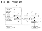
- a camera body 41 includes: an optical shooting system 42 with a lens, a CCD and the like; a camera signal processing circuit 43 for performing necessary processing upon a signal given from the optical image shooting system 42; an encoder 44 for encoding an image signal obtained from the camera signal processing circuit 43 by using JPEG or the like; an attachable/detachable memory card 47 into which an image signal obtained from the encoder 44 is to be written; a decoder 45 for decoding an image signal read from the memory card 47 by using JPEG or the like; a video output circuit 46 for outputting an image signal obtained from the decoder 45 to a display 49; and an interface 48 for making connection to a storage device 51.
- the storage device 51 includes: a card drive 52 for reading a signal from the memory card 47; an interface 53 to be connected to the interface 48 of the camera body 41; a storage medium 54 such as a hard disk or the like into which a signal obtained from the card drive 52 or from the interface 53 is recorded; a decoder 55 for decoding an image signal read from the storage medium 54 by using JPEG or the like; and a video output circuit 56 for outputting an image signal obtained from the decoder 55 to a display 57.
- a photographic file, a moving image file and an audio file created by shooting can be written into the memory card 47.
- the photographic file and the moving image file can also be displayed on the display 49 after being read from the memory card 47.
- a photographic file, a moving image file and an audio file written into the memory card 47 of the camera body 41 can be transmitted to the storage device 51.
- the photographic file and the moving image file can also be displayed on the display 57 connected to the storage device 51 after being read from the storage device 51.
- the storage device 51 is constituted for example by a personal computer. Transmission of a file written into the memory card 47 of the camera body 41 to the storage device 51 is controlled by a control circuit (not shown) provided to the storage device 51. With the memory card 47 of the camera body 41 regarded as a memory external to the storage device 51, the control circuit transmits a file read from the memory card 47 through the interfaces 48 and 53 to the storage medium 54 such as a hard disk or the like.
- the operation of the interface 48 is controlled for example by a USB device controller. While a file written into the memory card 47 of the camera body 41 can be transmitted to the storage device 51, depending on the interface 48, it may be impossible to write a file stored in the storage medium 54 back to the memory card 47 of the camera body 41. Accordingly, the decoder 55 and the video output circuit 56 should be provided to the storage device 51 in order to select a desirable file from multiple files accumulated in the storage medium 54 and to play back the selected file, which disadvantageously results in a complicated structure.
- the present invention is intended to provide an image capture device and an image capture system capable of storing multiple files in the external storage device, and capable of playing back and outputting a desirable file of the multiple files accumulated in the external storage device even in a structure in which a simple external storage device without a decoder or a video output circuit is connected.
- An image capture device of the present invention includes a main body which has an image capture function, and to and from which an external memory can be attached and detached.
- the main body includes: first signal processing means configured to create an image file by encoding image data obtained by image shooting; second signal processing means configured to create image data by decoding the image file created by the first signal processing means; a memory controller configured to write the image file obtained from the first signal processing means into the external memory, or to read an image file from the external memory; output means configured to output the image data obtained from the second signal processing means; an interface configured to make connection to an external storage device, the external storage device having a capacity larger than that of the external memory; a host controller configured to control transmission and receipt of data through the interface; and main control means configured to control operations of the memory controller and the host controller in order to transmit data between the external memory and the external storage device.
- An image capture system of the present invention is formed by connecting the external storage device to the interface of the image capture device of the present invention.
- data can be transmitted between the external memory and the external storage device.
- Files written in the external memory are transmitted through the interface to the external storage device, so that multiple files are recorded in the external storage device.
- a desirable file of the multiple files accumulated in the external storage device can be written back to the external memory through the interface.
- the file written in the external memory is thereafter supplied to the second signal processing means, and is thereafter decoded. Then, image data thereby obtained is output to a display, so that a still image or moving images can be played back.
- the main control means includes directory structure scaling up means configured to scale a directory structure in the external memory up to a directory structure in the external storage device when a file written in the external memory is transmitted to the external storage device.
- the main control means further includes directory structure scaling down means configured to scale a directory structure in the external storage device down to a directory structure in the external memory when a file stored in the external storage device is written back to the external memory.
- the directory structure in the external storage device contains a roll management directory which is arranged in a level higher than that of the directory section, and which manages the directory section as a unit roll, and a date management directory which is arranged in a level higher than that of the roll management directory, and which manages the date of each roll.
- the directory structure in the external memory is maintained as it is in the data transmission between the external memory and the external storage device. So, better access performance is obtained therebetween.
- the main control means has an image playback function for reading an image file from the external storage device, and for supplying the image file through the interface to the second signal processing means.
- a desirable file can be selected from the multiple files accumulated in the external storage device, and the selected file can be supplied through the interface to the second signal processing means.
- an image file is decoded to create image data, and the image data is then output to a display, so that a still image or moving images can be played back.
- the image capture device and the image capture system of the present invention even in a structure in which a simple external storage device without a decoder or a video output circuit is connected, multiple files can be recorded in the external storage device, and a desirable file of the multiple files accumulated in the external storage device can be played back and output.
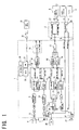
- a digital camera of the present invention has a camera body 1 including: an operation part 30; a CPU 31 for performing various control procedures in response to an operation signal from the operation part 30; and a memory 32 into which a control procedure to be performed by the CPU 31 is written.
- the CPU 31 and the memory 32 are connected to a bus 33.
- image signal light from an optical system 6 is converted to an electric signal in a CCD 8.
- the electric signal is A/D converted, and is supplied thereafter to a JPEG encoding circuit 11 and to an MPEG-4 video encoding circuit 12.
- An audio signal from a microphone 7 is A/D converted, and is supplied thereafter to an AAC audio encoding circuit 13.
- the JPEG encoding circuit 11 has an output terminal connected to the bus 33, and creates a photographic file under control of the CPU 31.
- the MPEG-4 video encoding circuit 12 and the AAC audio encoding circuit 13 have output terminals connected to the bus 33, and create a moving image file and an audio file under control of the CPU 31.
- the created photographic file is supplied through the bus 33 to a JPEG decoding circuit 20.
- the created moving image file is supplied through the bus 33 to an MPEG-4 video decoding circuit 21 and to an AAC audio decoding circuit 22.
- the created audio file is supplied to the MPEG-4 video encoding circuit 12.
- the outputs of the JPEG decoding circuit 20 and the MPEG-4 video decoding circuit 21 are converted to image data in a video encoder 23.
- the image data is then passed to a changeover switch SW1 and an output amplifier 24, and is thereafter output to an image output terminal 1b.
- the image data is also passed to an LCD driver 34, and is thereafter output to a liquid crystal display 35 by the switching of the changeover switch SW1.
- the output of the AAC audio decoding circuit 22 is converted to an audio signal in a D/A conversion circuit 25.
- the audio signal is then passed to an output amplifier 26 and a changeover switch SW2, and is thereafter output to an audio output terminal 1c.
- the audio signal is also passed to the output amplifier 26 and a speaker amplifier 36, and is thereafter output to a speaker 37 by the switching of the changeover switch SW2.
- the camera body 1 has a card drive 15 to and from which an external memory card 16 such as an SD card can be attached and detached.
- a memory controller 14 is placed between the card drive 15 and the bus 33.
- the camera body 1 also has a USB terminal 1a to which a USB interface 17 is connected.
- a USB device controller 18 and a USB host controller 19 are placed in parallel relation between the USB interface 17 and the bus 33.
- a cradle 2 can be connected to the USB terminal 1a, to the image output terminal 1b, and to the audio output terminal 1c of the camera body 1.
- the cradle 2 is provided with a USB device connector 27 and a USB host connector 28 to be connected in parallel relation to the USB terminal 1a, and an AV connector 29 to be connected to the image output terminal 1b and to the audio output terminal 1c.
- An external hard disk drive 3 can be connected to the USB host connector 28 of the cradle 2.
- a monitor television receiver 4 and a speaker 5 can be connected to the AV connector 29.
- the camera body 1 is provided with a light receiving part 38.
- the light receiving part 38 receives an infrared signal from a remote controller 39 and supplies the received signal to the CPU 31, thereby allowing remote control operation.
- the USB host controller 19 of the camera body 1 and the USB host connector 28 of the cradle 2 are novel constituent elements the conventional structure lacks. Further, control by the CPU 31 described later employs a novel control procedure the conventional structure lacks.
- An image capture system can be formed by connecting the external hard disk drive 3 to the camera body 1 through the cradle 2. As described later, this structure largely differs from the conventional structure in that a decoder or a video output circuit is not required to be connected to the external hard disk drive 3.
- the photographic file written in the external memory card 16 is thereafter read under control of the memory controller 14.
- the read photographic file is supplied to the JPEG decoding circuit 20 to obtain image data from the output amplifier 24.
- the image data is then supplied from the cradle 2 to the monitor television receiver 4, so that a still image can be played back.
- the moving image file written in the external memory card 16 is read under control of the memory controller 14.
- the read moving image file is supplied to the MPEG-4 video decoding circuit 21 and to the AAC audio decoding circuit 22 to obtain image data and an audio signal from the output amplifiers 24 and 26.
- the image data and the audio signal are then supplied from the cradle 2 to the monitor television receiver 4, so that moving images can be played back.
- the audio file written in the external memory card 16 is read under control of the memory controller 14.
- the read audio file is supplied to the AAC audio decoding circuit 22 to obtain an audio signal from the D/A conversion circuit 25.
- the audio signal is then supplied from the cradle 2 to the speaker 5, so that a sound can be played back.
- a photographic file obtained from the JPEG encoding circuit 11 of the camera body 1 is output through the USB interface 17 to the USB terminal 1a under control of the USB host controller 19.
- the output photographic file is then supplied from the USB host connector 28 of the cradle 2 to the external hard disk drive 3, so that a still image can be recorded in the external hard disk drive 3.
- a moving image file obtained from the MPEG-4 video encoding circuit 12 and the AAC audio encoding circuit 13 of the camera body 1 is output through the USB interface 17 to the USB terminal 1a under control of the USB host controller 19.
- the output moving image file is then supplied from the USB host connector 28 of the cradle 2 to the external hard disk drive 3, so that moving images can be recorded in the external hard disk drive 3.
- An audio file obtained from the AAC audio encoding circuit 13 of the camera body 1 is output through the USB interface 17 to the USB terminal 1a under control of the USB host controller 19.
- the output audio file is then supplied from the USB host connector 28 of the cradle 2 to the external hard disk drive 3, so that a sound can be recorded in the external hard disk drive 3.
- a file is read from the external memory card 16 under control of the memory controller 14 of the camera body 1.
- the read file is output through the USB interface 17 to the USB terminal 1a under control of the USB host controller 19, and is then supplied from the USB host connector 28 of the cradle 2 to the external hard disk drive 3.
- the file can be recorded in the external hard disk drive 3.
- a specific file stored in the external hard disk drive 3 is read, passed to the cradle 2, and loaded into the USB interface 17 of the camera body 1.
- the file obtained from the USB interface 17 can be written back to the external memory card 16 under control of the memory controller 14.
- a specific photographic file stored in the external hard disk drive 3 is passed to the cradle 2, and is then loaded into the USB interface 17 of the camera body 1.
- the file obtained from the USB interface 17 is supplied to the JPEG decoding circuit 20 to obtain image data from the output amplifier 24.
- the image data is passed to the cradle 2, and is then supplied to the monitor television receiver 4, so that a still image can be played back.
- a specific moving image file stored in the external hard disk drive 3 is passed to the cradle 2, and is then loaded into the USB interface 17 of the camera body 1.
- the file obtained from the USB interface 17 is supplied to the MPEG-4 video decoding circuit 21 and to the AAC audio decoding circuit 22 to obtain image data and an audio signal from the output amplifiers 24 and 26.
- the image data and the audio signal are passed to the cradle 2, and are then supplied to the monitor television receiver 4 and the speaker 5, so that moving images can be played back.
- a specific audio file stored in the external hard disk drive 3 is passed to the cradle 2, and is then loaded into the USB interface 17 of the camera body 1.
- the file obtained from the USB interface 17 is supplied to the AAC audio decoding circuit 22 to obtain an audio signal from the output amplifier 26.
- the audio signal is passed to the cradle 2, and is then supplied to the speaker 5, so that a sound can be played back.
- Fig. 26 shows a directory structure of files written in the external memory card 16 that employs the DCF standard.
- Fig. 27 shows a directory structure of files stored in the external hard disk drive 3.
- the DCF directory includes a folder "DCIM" placed in the root directory, and lower-level folders "100SANYO” to "999SANYO” that contain files of still images and moving images ("SANY0001" to "SANY9999”).
- the directory structure formed in the external hard disk drive 3 includes DCF directories in the lowest level each employing the directory structure formed in the external memory card 16 in its entirety.
- Roll management folders "ROLL001,” “ROLL0002,” ..., each of which is given a roll number with each DCF directory regarded as a unit, are created in a level higher than that of the DCF directories.
- a date management folder containing the date of transmission is newly created in a level higher than that of the roll management folders, and two or more rolls with the same date are transmitted to the same date management folder.
- a date management folder with a different date is newly created as a date changes.
- a media management folder is created in a level higher than that of the date management folders.
- a resource management folder, an album management folder, and an index file are created to be in parallel with the media management folder.
- a wallpaper image file, a BGM sound file, a switching effect masking file, and others are created in the resource management folder.
- Album files for setting the order of files to be played back, for setting the display period of still images, for setting switching effect, and for setting BGM are created in the album management folder.
- the DCF directory structures formed in the external memory card 16 and the external hard disk drive 3 described above allow a DCF directory to be maintained in data transmission between the external memory card 16 and the external hard disk drive 3. This provides extremely satisfactory access performance of files.
- Figs. 2 to 22 explain control procedures performed by the CPU 31 when an SD card is employed as the external memory card 16.
- Fig. 2 explains a basic flow.
- step S0 an initial checkup is conducted after startup to find a remaining battery level, the available space of the SD card, and the like. Thereafter the presence or absence of a USB cable being connected is determined in step S1.
- step S1 In a camera mode in which a USB cable is not connected, determination is made between a recording mode and a playback mode in step S2. Then, a mode setting is performed according to its result.
- step S3 the type of the cable is determined in step S3. If the cable is judged to be a USB host cable to which an external hard disk drive is connected, a drive structure is checked up in step S4. If there is no library structure, a library structure is formed in step S5, and the flow thereafter goes to step S6.
- step S6 selection is made from a main menu of four items TRANSMISSION, PLAYBACK, ALBUM, and DISCONNECTION. If TRANSMISSION is selected, the flow passes through step S7 to go to a transmission mode. If PLAYBACK is selected, the flow passes through step S8 to go to a playback mode. If ALBUM is selected, the flow passes through step S8' to go to an album mode. If DISCONNECTION is selected, the USB connection is disconnected in step S10, and then the procedure is completed.
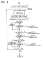
- a transmission direction is set to default "FROM SD (SD card) TO BOX (external hard disk drive)" in step S11.
- step S12 selection is made from a menu of four transmission modes TRANSMISSION EXECUTION, TRANSMISSION DIRECTION SETTING, INFORMATION DISPLAY, and MAIN MENU.
- the data volume of a transmission source is read in step S13, and the space of a transmission destination is read in step S14.
- step S18 If transmission is possible, it is determined in step S18 whether or not TRANSMISSION EXECUTION was selected. If its result is YES, the flow goes to TRANSMISSION EXECUTION. Further, it is determined in step S19 whether or not INFORMATION DISPLAY was selected. If its result is YES, the flow goes to TRANSMISSION DIRECTION SETTING. Still further, it is determined in step S20 whether or not the transmission direction is "FROM BOX TO SD.” If its result is NO, it is determined in step S21 whether or not POST-TRANSMISSION DELETION SETTING should be performed. If its result is YES, the flow goes to POST-TRANSMISSION DELETION SETTING.
- step S21 If a result of step S21 is NO, the flow goes to step S23. If a result of step S20 is YES, deletion setting is invalidated in step S22, and the flow thereafter goes to step S23. It is determined in step S23 whether or not the main menu should be displayed. If its result is NO, the flow returns to step S12. If its result is YES, the flow returns to step S6 of Fig. 2 .
- step S31 it is determined in step S31 whether a transmission direction is "FROM SD TO BOX.” If its result is NO, the flow goes to step S51 of Fig. 5 . In contrast, if a result of step S31 of Fig. 4 is YES, the flow goes to step S32 in which date and time information is read. Then, it is determined in step S33 whether the BOX contains a date folder with the same date. If its result is NO, a date folder with this date is created in step S34, and a roll number is set to "001" in step S34'.
- step S33 if a result of step S33 is YES, the flow goes to step S35 in which the last roll number is read from the date folder with the same date. Then, it is determined in step S36 whether or not the read roll number is at or below "999". If a result of step S36 is NO, an error is displayed in step S38. Thereafter the flow returns to step S12 of Fig. 3 . In contrast, if a result of step S36 of Fig. 4 is YES, 1 is added to the last roll number in step S37, and a result thereby obtained is employed as a roll number.
- a new roll management folder given the roll number is created in the BOX in step S39, and a DCIM folder is created in the new roll in step S40.
- a folder number is set to "100" according to the DCF standard in step S41, the number of folders in a DCIM folder in the SD card is counted in step S42, and the first folder in the SD card is set as a transmission source in step S43.
- step S44 a new folder given the folder number is created in the BOX in step S44, and data in the folder is transmitted from the SD card to the BOX in step S45.
- step S46 it is determined in step S46 whether or not there is a folder yet to be transmitted. If its result is YES, the flow goes to step S47 in which a next folder in the SD card is set as a transmission source. Then, a folder number is counted up in step S48.
- step S49 it is further determined in step S49 whether the data should be deleted after transmission. If its result is YES, the data in the SD card as a transmission source is deleted in step S50, and the flow thereafter returns to step S6 of Fig. 2 .
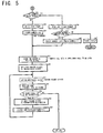
- step S31 of Fig. 4 it is first determine in step S51 of Fig. 5 whether or not there is a DCIM folder. If its result is NO, a DCIM folder is created in step S52, and then a folder number is set to "100" in step S53. If a result of step S51 is YES, the last folder number is read in step S54. Then, it is determined in step S55 whether or not the read folder number is at or below "999". If its result is NO, an error is displayed in step S57. Thereafter the flow returns to step S12 of Fig. 3 . In contrast, if a result of step S55 of Fig. 5 is YES, 1 is added to the last folder number in step S56, and a result thereby obtained is employed as a folder number.
- step S58 the number of folders in a roll is counted in step S58, and the first folder in the roll is set as a transmission source in step S59. Thereafter, a new folder given the folder number is created in the SD card in step S60, and data in the folder is transmitted from the BOX to the SD card in step S61. Next, it is determined in step S62 whether or not there is a folder yet to be transmitted. If its result is YES, a next folder in the BOX is set as a transmission source in step S63. Thereafter a folder number is counted up in step S64, and then the flow returns to step 60. If a next result of step S62 is NO, the flow returns to step S6 of Fig. 2 .
- a transmission direction is selected from “FROM SD TO BOX,” “FROM BOX TO SD,” and “CANCEL” in step S71 of Fig. 6 . If “FROM SD TO BOX” is determined in step S72, the flow goes to step S73 in which the transmission direction is set to "FROM SD TO BOX.” If “FROM BOX TO SD” is determined in step S74, the flow goes to step S75 in which the transmission direction is set to "FROM BOX TO SD.” After the display of a transmission direction is updated in step S76, the flow returns to step S12 of Fig. 3 . In contrast, if “CANCEL” is determined in step S74 of Fig. 6 , it is determined in step S77 whether or not canceling should be performed. If its result is NO, the flow returns to step S71. If its result is YES, the flow returns to step S12 of Fig. 3 .
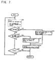
- step S81 of Fig. 7 display of information is selected from “BOX INFORMATION,” “SD CARD INFORMATION,” and “CANCEL” in step S81 of Fig. 7 .
- step S82 the flow goes to step S83 in which the available space of the BOX and the number of rolls stored are read.
- step S85 in which SD data volume and the number of files are read.
- step S86 an information display screen is updated in step S86, and the flow thereafter returns to step S12 of Fig. 3 .
- step S87 it is determined in step S87 whether or not canceling should be performed. If its result is NO, the flow returns to step S81. If its result is YES, the flow returns to step S12 of Fig. 3 .
- step S91 of Fig. 8 selection is made between "DELETE AFTER TRANSMISSION” and “NOT DELETE AFTER TRANSMISSION” in step S91 of Fig. 8 . If “DELETE AFTER TRANSMISSION” is determined in step S92, “DELETE” is set ON in step S94. If “NOT DELETE AFTER TRANSMISSION” is determined in step S93, “DELETE” is set OFF in step S95, and then the flow returns to step S12 of Fig. 3 . In contrast, no determination is made in step S93 of Fig. 8 , it is determined in step S96 whether or not canceling should be performed. If its result is NO, the flow returns to step S91. If its result is YES, the flow returns to step S12 of Fig. 3 .
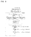
- step S101 of Fig. 9 In the playback mode, default "BOX” is set by default as media setting in step S101 of Fig. 9 , and "ROLL VIEW” is set as view setting in step S102. Thereafter in step S103, it is determined which one of "ROLL,” “CALENDAR,” and “SD CARD” is set in the view setting.
- a roll view display such as a roll selection list and view selection (see Fig. 23(d) ) is presented in step S104.
- a calendar view display such as a date selection list and view selection (see Fig. 23(e) ) is presented in step S105.
- a roll selection display such as a roll selection list and view selection (see Fig. 23(g) ) is presented in step S107.
- SD CARD is set, an SD card view display such as card selection (see Fig. 23(f) ) is presented in step S106. Roll information is thereby read and a selection list is displayed according to each view setting, so that a roll to be played back is specified.
- step S108 It is determined in step S108 whether or not a roll to be played back is decided. If its result is YES, the flow goes to a roll playback procedure (B-1). Next, it is determined in step S109 whether or not view selection was made. If its result is YES, the flow goes to a view selection procedure (B-3). Further, it is determined in step S110 whether or not a "T" key was operated. If its result is YES, the flow goes to a folder selection procedure (B-4). If a result of step S110 is NO, the flow returns to step S103 to repeat determination, of the view setting.
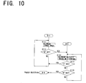
- step S112 determines whether or not a "W" key was operated. If its result is NO, the flow returns to step S111 to continue the playback of the single image. If a result of step S112 is YES, multiple images are played back on nine screens (see Fig. 23(i) ) in step S113. Then, it is determined in step S114 whether or not the "T" key was operated. If its result is YES, the flow returns to step S111 to play back a single image.
- step S114 If a result of step S114 is NO, the flow goes to step S115 in which it is determined whether or not the "W" key was operated. If its result is NO, the flow returns to step S113 to continue the playback of the multiple images on nine screens. If its result is YES, the flow goes to the folder selection (B-4). As described, in the roll playback, a playback mode incorporated as an original camera function is employed when a roll to be played back is decided.
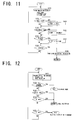
- a view selection display for making selection from "ROLL VIEW,” “CALENDAR VIEW,” and “SD CARD VIEW” (see Figs. 23(a), (b), (c) ) is presented in step S131 of Fig. 11 .
- a roll is set to "VIEW” in step S133.
- CALENDAR VIEW is determined in step S134, a calendar is set to "VIEW” in step S135.
- SD CARD VIEW" is determined in step S136, an SD card is set to "VIEW” in step S137.
- step S122 it is determined in step S122 whether or not a folder to be played back is decided. If its result is YES, the flow goes to the playback mode (B-1). If a result of step S122 is NO, the flow goes to step S123 in which it is determined whether or not an operation for roll selection was performed. If its result is YES, the flow returns to step S103 of Fig. 9 to perform roll selection.
- step S123 If a result of step S123 is NO, the flow goes to step S124 in which it is determined whether or not the "W" key was operated. If its result is YES, the flow returns to step S103 of Fig. 9 to perform roll selection. In contrast, if a result of step S124 is NO, the flow goes to step S125 in which it is determined whether or not the "T" key was operated. If its result is NO, the flow returns to step S121 to repeat the display of the folder selection screen. If its result is YES, the flow goes to step S113 of Fig. 10 in which multiple images are played back on nine screens.
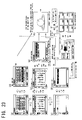
- Fig. 23 shows transitions of a series of display screens in response to operations when "PLAYBACK” is selected from “DATA TRANSMISSION,” “PLAYBACK,” and “ALBUM” on the main menu.
- a roll (date) view of Fig. 23(d) is displayed.
- a roll number and a date are displayed as a pair.
- a predetermined single file contained in the selected roll such as the last file in the last folder
- a target of display can be switched to a next file by operating an image-feed key, with one file displayed as shown in (h).
- a target of display can be switched among folders. If a target of display is to be switched to a different roll, a roll is selected first.
- an SD card view switching screen of (c) appears.
- an SD card view of (f) appears.
- an indication that a card is a target of playback is displayed.
- a predetermined single file can directly be displayed as shown in (h) only by selecting one roll in the roll (date) view of Fig. 23(d) . Then, display is switched to a next image in this state, so that a desirable single image can be displayed. Or, after a roll is selected on the roll (date) view of Fig. 23(d) , a folder is selected on the folder selection screen of (j), and a file is selected on the display of multiple screens of (i), a desirable single file can finally be displayed as shown in (h). Thus, a user can select a preferable way from these two ways of file display.
- step S141 of Fig. 13 a list of album files already created is searched first, and a result thereof is displayed in step S141 of Fig. 13 .
- step S142 an album menu is displayed on which it is determined whether an album to be played back should be selected from the album list, whether an album should be edited (changed), whether an album should be deleted, or whether an album should be newly played back (see Fig. 24(b) ).
- step S143 If an album to be played back is selected, the flow goes to an album playback procedure (C-1) in step S143. If NEW ALBUM CREATION is selected, the flow goes to a new album creation procedure (C-2) in step S144. If ALBUM EDITION is selected, the flow goes to an album edition procedure (C-3) in step S145. If ALBUM DELETION is selected, the flow goes to an album deletion procedure (album deletion) in step S146. If MAIN MENU is selected, the main menu is displayed again in step S147.
- step S151 of Fig. 14 the first file in an album is displayed in step S151 of Fig. 14 , and thereafter, playback of the album is started in step S152. Then, it is determined in step S153 whether or not an operation for stopping the album playback was performed. If its result is YES, the flow returns to step S141 of Fig. 13 in which the search of the album list and display are performed. If a result of step S153 of Fig. 14 is NO, the flow goes to step S154 in which it is determined whether or not the album has been played back to the end. If its result is YES, the flow returns to step S141 of Fig. 13 in which the search and display of the album list are performed.
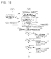
- a file counter FC, a file pointer F_PTR, and an insert pointer I_PTR are each set to zero in step S163, and the flag of an edit marker is set to "False” in step S164. Thereafter the flow goes to step S167.
- the file counter FC is read, and the file pointer F_PTR and the insert pointer I_PTR are each set to zero in step S165 of Fig. 15 . Further, the flag of an edit marker is set to "True” in step S166. Thereafter the flow goes to step S167.
- step S167 the head of the last roll is designated first as a reference position of a file when it is added.
- step S169 the display of an album creation operation screen is updated in step S168.
- step S169 it is determined in step S169 whether or not file addition was instructed. If its result is YES, an "insert pointer” described later is displayed in step S170, and "ADD" is thereafter set as a command variable cmd.
- step S172 whether or not file move was instructed. If its result is YES, a "file pointer” described later is displayed in step S173, and "MOVE" is thereafter set as the command variable cmd. Further, it is determined in step S175 whether or not file deletion was instructed. If its result is YES, a "file pointer” is displayed in step S176, and "DELETE" is thereafter set as the command variable cmd.
- step S178 of Fig. 16 it is determined in step S178 of Fig. 16 whether or not an operation for bringing the pointers forward was performed. If its result is YES, it is determined in step S179 whether or not the pointers can be moved. If its result is YES, the flow goes to step S180 in which the file pointer F_PTR and the insert pointer I_PTR are each counted up by one. Next, it is determined in step S181 whether or not an operation for bringing the pointers backward was performed. If its result is YES, it is determined in step S182 whether or not the pointers can be moved. If its result is YES, the flow goes to step S183 in which the file pointer F_PTR and the insert pointer I_PTR are each counted down by one.
- step S184 it is determined in step S184 whether or not an operation for executing the command variable cmd was performed. If its result is YES, it is determined in step S185 whether or not the command variable cmd is "ADD.” If its result is YES, the flow goes to an addition procedure described later. It is determined in step S186 whether or not the command variable cmd is "MOVE.” If its result is YES, the flow goes to a move procedure described later. Further, it is determined in step S187 whether or not the command variable cmd is "DELETE.” If its result is YES, the flow goes to a deletion procedure described later.
- step S184 If a result of step S184 is NO, the flow goes to step S188 in which it is determined whether or not NEW ALBUM CREATION or ALBUM EDITION is completed. If its result is NO, the flow returns to step S168 of Fig. 15 to update the display of the album creation operation screen. In contrast, if a result of step S188 of Fig. 16 is YES, the flow goes to an album setting procedure described later.
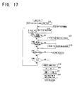
- step S193 the position of an additional file is read in step S191 of Fig. 17 , and an additional file selection screen containing a file list (see Fig. 24(f) ) is displayed in step S192. Then, it is determined in step S193 whether or not an operation for bringing file selection forward was performed. If its result is YES, a selection mark is brought forward in step S194. Next, it is determined in step S195 whether or not an operation for bringing file selection backward was performed. If its result is YES, a selection mark is brought backward in step S196. The move is performed in this way under the same condition as that in the playback mode. Next, it is determined in step S197 whether or not an operation for folder selection was performed. If its result is YES, the flow goes to a folder selection procedure described later.
- step S197 it is determined in step S198 whether or not an operation for accepting the selected file was performed. If its result is NO, the flow returns to step S192 so that the additional file selection screen continues to be displayed. In contrast, if a result of step S198 is YES, the flow goes to step S199 in which the album file is operated to add the selected file to the position of the insert pointer I_PTR.
- step S200 the file counter FC is counted up by one in step S200, and the file pointer F_PTR and the insert pointer I_PTR are each counted up by one in step S201.
- the pointers are thereby incremented according to the additional file.
- the position of the additional file is saved in step S202, and the flow thereafter returns to step S167 of Fig. 15 .
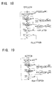
- a folder selection screen containing a folder list (see Fig. 24(g) ) is displayed in step S211. Then, it is determined in step S212 whether or not an operation for bringing folder selection forward was performed. If its result is YES, a selection mark is brought forward in step S213. Next, it is determined in step S214 whether or not an operation for bringing folder selection backward was performed. If its result is YES, a selection mark is brought backward in step S215. It is also determined in step S216 whether or not an operation for roll selection was performed. If its result is YES, the flow goes to a roll selection procedure described later.
- step S216 determines whether or not an operation for accepting the selected folder was performed. If its result is NO, the flow returns to step S211 so that the folder selection screen continues to be displayed. In contrast, if a result of step S217 is YES, the flow returns to step S192 of Fig. 17 to display the additional file selection screen.
- a roll selection screen containing a roll list (see Fig. 24(h) ) is displayed in step S221 of Fig 19 . Then, it is determined in step S222 whether or not an operation for bringing roll selection forward was performed. If its result is YES, a selection mark is brought forward in step S223. Next, it is determined in step S224 whether or not an operation for bringing roll selection backward was performed. If its result is YES, a selection mark is brought backward in step S225. Next, it is determined in step S226 whether or not an operation for accepting the selected roll was performed. If its result is NO, the flow returns to step S221 so that the roll selection screen continues to be displayed. If a result of step S226 is YES, the flow returns to step S211 of Fig. 18 to display the folder selection screen.
- step S231 of Fig. 20 an indication for conforming a file to be moved is displayed in step S231 of Fig. 20 , and thereafter, an "insert pointer" (see Fig. 24(j) ) is displayed in step S232.
- step S233 it is determined in step S233 whether or not an operation for bringing the insert pointer forward was performed. If its result is YES, it is determined in step S234 whether or not the insert pointer can be moved. If its result is YES, the insert pointer I_PTR is counted up by one in step S235, and the display of the album creation operation screen is updated in step S236.
- step S237 it is determined in step S237 whether or not an operation for bringing the insert pointer backward was performed. If its result is YES, it is determined in step S238 whether or not the insert pointer can be moved. If its result is YES, the insert pointer I_PTR is counted down by one in step S239, and the display of the album creation operation screen is updated in step 5240.
- step S241 it is determined in step S241 whether or not specification of a location to which the file is to be moved is completed. If its result is NO, the flow returns to step S233 to continue the move of the insert pointer. In contrast, if a result of step S241 is YES, the flow goes to step S242 in which the album file is operated and the file to be moved is moved to the position of the insert pointer I_PTR. Then, the flow returns to step S167 of Fig. 15 .
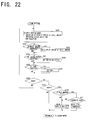
- step S261 of Fig. 22 an album setting menu including selection of display period of still images, selection of switching effect, selection of BGM and the like is displayed in step S261 of Fig. 22 .
- step S262 it is determined in step S262 whether or not "DISPLAY PERIOD OF STILL IMAGES” was selected. If its result is YES, the flow goes to step S263 to set the display period of still images.
- step S264 whether or not "SWITCHING EFFECT” was selected. If its result is YES, the flow goes to step S265 to set switching effect. It is also determined in step S266 whether or not "BGM” was selected. If its result is YES, the flow goes to step S267 to set BGM.
- step S268 it is determined in step S268 whether or not an operation for saving the album setting was performed. If its result is NO, the flow returns to step S261 so that the setting menu continues to be displayed. If a result of step S268 is YES, it is further determined in step S269 whether or not the album setting was saved. If its result is NO, the flow returns to step S141 of Fig. 13 to repeat the procedures on the album menu.
- step S269 if a result of step S269 is YES, the flow goes to step S270 in which it is determined whether or not an edit marker is "True.” If its result is NO, it is judged that a newly created album is being processed. Then, the new album is saved in step S272, and the flow thereafter returns to step S141 of Fig. 13 to repeat the procedures on the album menu.
- step S270 of Fig. 22 if a result of step S270 of Fig. 22 is YES, it is judged that the already existing album is being edited. Then, it is further determined in step S271 whether or not the album is to be overwritten. If its result is NO, the flow goes to step S272 to perform a newly save. If its result is YES, the flow goes to step S273 to overwrite the album. Thereafter the flow returns to step S141 of Fig. 13 to repeat the procedures on the album menu.
- Fig. 24 shows transitions of a series of display screens in response to operations when "ALBUM” is selected from “DATA TRANSMISSION,” “PLAYBACK,” and “ALBUM” on the main menu.
- “ALBUM” is selected from the main menu including "DATA TRANSMISSION,” “PLAYBACK,” and “ALBUM” on the main menu shown in Fig. 24(a)
- a selection screen of an album file to be played back is displayed as shown in (b).
- the selected album file can be played back.
- the selected, album file is displayed in a box in dashed lines as shown in (d). If the selection is confirmed, selection buttons "ADD,” “MOVE,” and “DELETE” appear as shown in (e).
- an insert pointer indicating an insertion position of a file appears in the form of a triangular mark. After the insertion position is determined by a key operation, a file to be added can be designated while switching is made among the file selection screen shown in (f), the folder selection screen shown in (g), and the roll selection screen shown in (h). After one file is selected from the file selection screen of (f), the screen of (e) is displayed again. Then, the selected file is inserted into the position of the insert pointer, by which the file is added.
- a file to be moved is displayed in a box in bold lines as shown in (i).
- the selected file is indicated by a file pointer (box in dashed lines) as shown in (j), and the thumbnail image of the selected file is displayed at all times on the screen.
- an insert pointer triangular mark
- the insert pointer is moved to designate the destination. If a file to be moved disappears from the screen as a result of scrolling in this process, the thumbnail of the file to be moved is displayed on the screen, so that no inconvenience is caused.
- a sequence of files including the file to be moved that has been moved to the destination is displayed as shown in (k).
- Fig. 25 shows how a file is added and moved using the pointers described above.
- an insert pointer in the form of a triangular mark appears, and a new file "New" is inserted into the position of the insert pointer.
- a file "A" selected as a file to be moved is identified by a pointer in the form of a box in bold lines.
- the file to be moved is confirmed, the file is identified by a file pointer in the form of a box in dashed lines. Then, the file identified by the file pointer is moved to the position of an insert pointer in the form of a triangular mark.
- a file and a position can be selected among folders or rolls.
- a file can freely be added to a file list of files to be played back, or moved.
- file selected as a file to be deleted is identified by a pointer in the form of a box in bold lines.
- the file identified by the pointer is removed from the file list by executing deletion.
- the file itself is not deleted.
- the digital camera of the present invention described above has a structure in which the external hard disk drive 3 is connected through the cradle 2 to the camera body 1 as shown in Fig. 1 .
- a file written in the external memory card 16 can be transmitted to the external hard disk drive 3 under control of the CPU 31 of the camera body 1.
- this does not require control of data transmission by a personal computer by connecting the personal computer to an external hard disk drive, thereby providing convenience.
- a desirable file is selected from a plurality of files accumulated in the external hard disk drive 3, and the selected file is loaded into the camera body 1. Then, the file is decoded in the JPEG decoding circuit 20, the MPEG-4 video decoding circuit 21, or the AAC audio decoding circuit 22 incorporated in the camera body 1, so that an image or a sound can be played back. So, unlike the conventional structure, this does not require a decoder or a video output circuit to be connected to an external hard disk drive, thereby simplifying a structure.
- the structure of each part of the present invention is not limited to that shown in the embodiment described above.
- Various modifications may be devised within the technical scope defined in claims.
- the embodiment shown in Fig. 1 employs a structure in which the cradle 2 is connected to the camera body 1.
- the USB device connector 27, the USB host connector 28 and the AV connector 29 of the cradle 2 may be provided in the camera body 1, so that the cradle 2 can be omitted.
- the external memory card 16 such as an SD card is employed as an external memory
- the external hard disk drive 3 is employed as an external storage device, to which the present invention is not intended to be confined.
- Various types of known external memories and external storage devices may be employed.
Landscapes
- Engineering & Computer Science (AREA)
- Multimedia (AREA)
- Signal Processing (AREA)
- Television Signal Processing For Recording (AREA)
- Studio Devices (AREA)
- Information Retrieval, Db Structures And Fs Structures Therefor (AREA)
- Processing Or Creating Images (AREA)
Priority Applications (1)
| Application Number | Priority Date | Filing Date | Title |
|---|---|---|---|
| EP10007850A EP2247103A1 (de) | 2007-03-27 | 2008-03-25 | Bildaufnahmevorrichtung und -system |
Applications Claiming Priority (4)
| Application Number | Priority Date | Filing Date | Title |
|---|---|---|---|
| JP2007082692 | 2007-03-27 | ||
| JP2007206521 | 2007-08-08 | ||
| JP2007227898A JP5116407B2 (ja) | 2007-03-27 | 2007-09-03 | 撮像装置及び撮像システム |
| PCT/JP2008/055529 WO2008117791A1 (ja) | 2007-03-27 | 2008-03-25 | 撮像装置及び撮像システム |
Publications (2)
| Publication Number | Publication Date |
|---|---|
| EP2136557A1 true EP2136557A1 (de) | 2009-12-23 |
| EP2136557A4 EP2136557A4 (de) | 2010-04-07 |
Family
ID=39788525
Family Applications (2)
| Application Number | Title | Priority Date | Filing Date |
|---|---|---|---|
| EP10007850A Withdrawn EP2247103A1 (de) | 2007-03-27 | 2008-03-25 | Bildaufnahmevorrichtung und -system |
| EP08738824A Ceased EP2136557A4 (de) | 2007-03-27 | 2008-03-25 | Bildaufnahmevorrichtung und bildaufnahmesystem |
Family Applications Before (1)
| Application Number | Title | Priority Date | Filing Date |
|---|---|---|---|
| EP10007850A Withdrawn EP2247103A1 (de) | 2007-03-27 | 2008-03-25 | Bildaufnahmevorrichtung und -system |
Country Status (5)
| Country | Link |
|---|---|
| US (1) | US8319849B2 (de) |
| EP (2) | EP2247103A1 (de) |
| JP (1) | JP5116407B2 (de) |
| CN (4) | CN102547129A (de) |
| WO (1) | WO2008117791A1 (de) |
Families Citing this family (16)
| Publication number | Priority date | Publication date | Assignee | Title |
|---|---|---|---|---|
| JP4601652B2 (ja) * | 2007-03-27 | 2010-12-22 | 三洋電機株式会社 | 撮像装置 |
| CN102202202B (zh) * | 2010-03-24 | 2013-01-02 | 华晶科技股份有限公司 | 可选径的影像管线装置 |
| US9396354B1 (en) | 2014-05-28 | 2016-07-19 | Snapchat, Inc. | Apparatus and method for automated privacy protection in distributed images |
| US9537811B2 (en) | 2014-10-02 | 2017-01-03 | Snap Inc. | Ephemeral gallery of ephemeral messages |
| US9113301B1 (en) | 2014-06-13 | 2015-08-18 | Snapchat, Inc. | Geo-location based event gallery |
| US10824654B2 (en) | 2014-09-18 | 2020-11-03 | Snap Inc. | Geolocation-based pictographs |
| US11216869B2 (en) | 2014-09-23 | 2022-01-04 | Snap Inc. | User interface to augment an image using geolocation |
| US10284508B1 (en) | 2014-10-02 | 2019-05-07 | Snap Inc. | Ephemeral gallery of ephemeral messages with opt-in permanence |
| US10311916B2 (en) | 2014-12-19 | 2019-06-04 | Snap Inc. | Gallery of videos set to an audio time line |
| US9385983B1 (en) | 2014-12-19 | 2016-07-05 | Snapchat, Inc. | Gallery of messages from individuals with a shared interest |
| US10133705B1 (en) | 2015-01-19 | 2018-11-20 | Snap Inc. | Multichannel system |
| KR102662169B1 (ko) | 2015-03-18 | 2024-05-03 | 스냅 인코포레이티드 | 지오-펜스 인가 프로비저닝 |
| US10135949B1 (en) | 2015-05-05 | 2018-11-20 | Snap Inc. | Systems and methods for story and sub-story navigation |
| US10354425B2 (en) | 2015-12-18 | 2019-07-16 | Snap Inc. | Method and system for providing context relevant media augmentation |
| US10582277B2 (en) | 2017-03-27 | 2020-03-03 | Snap Inc. | Generating a stitched data stream |
| US10581782B2 (en) | 2017-03-27 | 2020-03-03 | Snap Inc. | Generating a stitched data stream |
Family Cites Families (29)
| Publication number | Priority date | Publication date | Assignee | Title |
|---|---|---|---|---|
| JP3103151B2 (ja) | 1990-09-03 | 2000-10-23 | 富士写真フイルム株式会社 | 電子スチル・カメラおよびその動作制御方法 |
| JP3015183B2 (ja) * | 1991-12-16 | 2000-03-06 | 富士写真フイルム株式会社 | ディジタル電子スチル・カメラ |
| JP3342146B2 (ja) | 1993-12-29 | 2002-11-05 | キヤノン株式会社 | 画像情報管理装置 |
| JPH10108122A (ja) * | 1996-09-26 | 1998-04-24 | Nikon Corp | 画像再生装置 |
| JP3096684B2 (ja) * | 1998-03-25 | 2000-10-10 | 三洋電機株式会社 | デジタルカメラ |
| JP2000196986A (ja) * | 1998-12-25 | 2000-07-14 | Olympus Optical Co Ltd | 電子的撮像装置 |
| US6976229B1 (en) * | 1999-12-16 | 2005-12-13 | Ricoh Co., Ltd. | Method and apparatus for storytelling with digital photographs |
| JP2002135692A (ja) * | 2000-10-27 | 2002-05-10 | Toshiba Corp | 電子カメラ装置及びファイル管理方法 |
| JP2002140219A (ja) * | 2000-11-01 | 2002-05-17 | Toshiba Corp | ファイル処理方法、ファイル処理装置、ファイル管理用記録媒体 |
| JP4532759B2 (ja) * | 2001-02-23 | 2010-08-25 | キヤノン株式会社 | 撮像装置 |
| JP2002278996A (ja) * | 2001-03-22 | 2002-09-27 | Sony Corp | 記録装置および記録方法、並びに記録媒体 |
| JP2002359763A (ja) | 2001-06-01 | 2002-12-13 | Fuji Photo Film Co Ltd | デジタルカメラ用スタンド |
| JP2003114820A (ja) | 2001-07-31 | 2003-04-18 | Sanyo Electric Co Ltd | 電子アルバム装置 |
| US7444354B2 (en) * | 2001-09-14 | 2008-10-28 | Fujifilm Corporation | Method and apparatus for storing images, method and apparatus for instructing image filing, image storing system, method and apparatus for image evaluation, and programs therefor |
| JP2003091441A (ja) | 2001-09-18 | 2003-03-28 | Nikon System:Kk | 画像処理装置および方法、記録媒体、並びにプログラム |
| KR100563670B1 (ko) * | 2002-01-28 | 2006-03-28 | 엘지전자 주식회사 | 재기록 가능 고밀도 기록매체의 정지영상 기록방법 |
| JP4005470B2 (ja) * | 2002-10-09 | 2007-11-07 | オリンパス株式会社 | 情報処理装置及び情報処理プログラム |
| US20040213092A1 (en) * | 2003-04-23 | 2004-10-28 | Konica Minolta Photo Imaging, Inc. | Input data recording apparatus, and input data recording method |
| US7295933B2 (en) * | 2003-07-15 | 2007-11-13 | Cidra Corporation | Configurable multi-function flow measurement apparatus having an array of sensors |
| JP4168268B2 (ja) * | 2003-07-16 | 2008-10-22 | 富士フイルム株式会社 | 電子機器 |
| US7840892B2 (en) * | 2003-08-29 | 2010-11-23 | Nokia Corporation | Organization and maintenance of images using metadata |
| JP2005149170A (ja) * | 2003-11-17 | 2005-06-09 | Innotech Corp | データ送受信システムおよびデータ送受信プログラム |
| JP2004229328A (ja) * | 2004-05-06 | 2004-08-12 | Olympus Corp | 電子的撮像装置 |
| WO2006009023A1 (ja) * | 2004-07-21 | 2006-01-26 | Konica Minolta Holdings, Inc. | 情報生成装置及び情報生成プログラム |
| JP2006246120A (ja) | 2005-03-04 | 2006-09-14 | Noritsu Koki Co Ltd | 画像プリント処理装置 |
| US20060209214A1 (en) * | 2005-03-17 | 2006-09-21 | Xerox Corporation | Digital photo album systems and methods |
| JP4725183B2 (ja) | 2005-05-11 | 2011-07-13 | ソニー株式会社 | 撮像装置、および方法 |
| US20060290788A1 (en) * | 2005-06-27 | 2006-12-28 | Fuji Photo Film Co., Ltd | Image capturing apparatus, control method and program therefor |
| US8106856B2 (en) * | 2006-09-06 | 2012-01-31 | Apple Inc. | Portable electronic device for photo management |
-
2007
- 2007-09-03 JP JP2007227898A patent/JP5116407B2/ja not_active Expired - Fee Related
-
2008
- 2008-03-25 CN CN2012100484000A patent/CN102547129A/zh active Pending
- 2008-03-25 EP EP10007850A patent/EP2247103A1/de not_active Withdrawn
- 2008-03-25 WO PCT/JP2008/055529 patent/WO2008117791A1/ja not_active Ceased
- 2008-03-25 EP EP08738824A patent/EP2136557A4/de not_active Ceased
- 2008-03-25 US US12/593,451 patent/US8319849B2/en not_active Expired - Fee Related
- 2008-03-25 CN CN2012100483987A patent/CN102611848A/zh active Pending
- 2008-03-25 CN CN2012100482819A patent/CN102611847A/zh active Pending
- 2008-03-25 CN CN2008800095589A patent/CN101652992B/zh not_active Expired - Fee Related
Also Published As
| Publication number | Publication date |
|---|---|
| CN101652992A (zh) | 2010-02-17 |
| CN101652992B (zh) | 2012-06-27 |
| CN102611848A (zh) | 2012-07-25 |
| WO2008117791A1 (ja) | 2008-10-02 |
| US8319849B2 (en) | 2012-11-27 |
| EP2136557A4 (de) | 2010-04-07 |
| US20100073509A1 (en) | 2010-03-25 |
| CN102547129A (zh) | 2012-07-04 |
| CN102611847A (zh) | 2012-07-25 |
| EP2247103A1 (de) | 2010-11-03 |
| JP5116407B2 (ja) | 2013-01-09 |
| JP2009060510A (ja) | 2009-03-19 |
Similar Documents
| Publication | Publication Date | Title |
|---|---|---|
| EP2247103A1 (de) | Bildaufnahmevorrichtung und -system | |
| JP4354806B2 (ja) | 動画像管理装置及び方法 | |
| US7617107B2 (en) | Information processing device and information processing program | |
| JP3402659B2 (ja) | 画像取り扱い装置 | |
| CN101431610B (zh) | 摄像设备 | |
| CN1908884B (zh) | 电子设备、数据处理方法、数据控制方法和内容数据处理系统 | |
| KR20080060155A (ko) | 정보 처리 장치, 정보 처리 방법, 프로그램 | |
| KR20070003611A (ko) | 파일 액세스 방법, 특정 이미지 파일 재생 방법, 및 이미지파일을 재생할 수 있는 카메라 장치 | |
| EP2134088A1 (de) | Bildverarbeitungsvorrichtung | |
| JP5165038B2 (ja) | 画像処理装置 | |
| JP4677373B2 (ja) | 撮像装置、システム及びそれらの制御方法、プログラム、記憶媒体 | |
| JP4677352B2 (ja) | 記録再生装置及び記録再生方法 | |
| JP3820252B2 (ja) | 画像取り扱い装置 | |
| JPH06225194A (ja) | カメラ | |
| JP2009296053A (ja) | 撮像装置及びその制御方法、並びに撮像システム | |
| JP2001061128A (ja) | 撮像装置 | |
| JP2007122793A (ja) | 再生装置 | |
| JP2004129312A (ja) | 画像取り扱い装置 | |
| JP2004056814A (ja) | 電子カメラシステム | |
| JP2004104770A (ja) | 電子カメラシステム | |
| JPH0728853A (ja) | 画像取り扱い装置 | |
| JPH11317929A (ja) | 画像再生装置 | |
| JP2004064778A (ja) | 電子カメラ | |
| JPH0728453A (ja) | 画像取り扱い装置 | |
| JPH0730841A (ja) | 画像取り扱い装置 |
Legal Events
| Date | Code | Title | Description |
|---|---|---|---|
| PUAI | Public reference made under article 153(3) epc to a published international application that has entered the european phase |
Free format text: ORIGINAL CODE: 0009012 |
|
| 17P | Request for examination filed |
Effective date: 20090928 |
|
| AK | Designated contracting states |
Kind code of ref document: A1 Designated state(s): AT BE BG CH CY CZ DE DK EE ES FI FR GB GR HR HU IE IS IT LI LT LU LV MC MT NL NO PL PT RO SE SI SK TR |
|
| A4 | Supplementary search report drawn up and despatched |
Effective date: 20100308 |
|
| RIC1 | Information provided on ipc code assigned before grant |
Ipc: H04N 5/77 20060101ALI20100302BHEP Ipc: H04N 5/225 20060101ALI20100302BHEP Ipc: H04N 9/804 20060101ALI20100302BHEP Ipc: H04N 5/91 20060101AFI20081015BHEP Ipc: H04N 5/765 20060101ALI20100302BHEP |
|
| DAX | Request for extension of the european patent (deleted) | ||
| RIC1 | Information provided on ipc code assigned before grant |
Ipc: H04N 5/77 20060101ALI20101130BHEP Ipc: H04N 9/804 20060101ALI20101130BHEP Ipc: H04N 5/765 20060101ALI20101130BHEP Ipc: H04N 5/225 20060101ALI20101130BHEP Ipc: H04N 5/91 20060101AFI20101130BHEP |
|
| 17Q | First examination report despatched |
Effective date: 20110126 |
|
| REG | Reference to a national code |
Ref country code: DE Ref legal event code: R003 |
|
| STAA | Information on the status of an ep patent application or granted ep patent |
Free format text: STATUS: THE APPLICATION HAS BEEN REFUSED |
|
| 18R | Application refused |
Effective date: 20111117 |