EP2136261A2 - Aufzeichnungsmedium-Positionierungsvorrichtung und Bilderzeugungsvorrichtung mit der Vorrichtung - Google Patents
Aufzeichnungsmedium-Positionierungsvorrichtung und Bilderzeugungsvorrichtung mit der Vorrichtung Download PDFInfo
- Publication number
- EP2136261A2 EP2136261A2 EP09251577A EP09251577A EP2136261A2 EP 2136261 A2 EP2136261 A2 EP 2136261A2 EP 09251577 A EP09251577 A EP 09251577A EP 09251577 A EP09251577 A EP 09251577A EP 2136261 A2 EP2136261 A2 EP 2136261A2
- Authority
- EP
- European Patent Office
- Prior art keywords
- recording
- shift
- medium
- recording medium
- sheet
- Prior art date
- Legal status (The legal status is an assumption and is not a legal conclusion. Google has not performed a legal analysis and makes no representation as to the accuracy of the status listed.)
- Withdrawn
Links
- 238000011144 upstream manufacturing Methods 0.000 claims abstract description 11
- 238000000926 separation method Methods 0.000 claims description 3
- 238000012546 transfer Methods 0.000 description 32
- 238000010586 diagram Methods 0.000 description 14
- 230000015572 biosynthetic process Effects 0.000 description 8
- 230000009471 action Effects 0.000 description 3
- 238000006073 displacement reaction Methods 0.000 description 3
- 238000000034 method Methods 0.000 description 3
- 230000007935 neutral effect Effects 0.000 description 3
- 230000008569 process Effects 0.000 description 3
- 238000012360 testing method Methods 0.000 description 3
- 230000015556 catabolic process Effects 0.000 description 2
- 238000004140 cleaning Methods 0.000 description 2
- 230000007423 decrease Effects 0.000 description 2
- 238000006731 degradation reaction Methods 0.000 description 2
- 238000012986 modification Methods 0.000 description 2
- 230000004048 modification Effects 0.000 description 2
- 238000005452 bending Methods 0.000 description 1
- 238000006243 chemical reaction Methods 0.000 description 1
- 239000003086 colorant Substances 0.000 description 1
- 238000012937 correction Methods 0.000 description 1
- 230000000593 degrading effect Effects 0.000 description 1
- 238000001514 detection method Methods 0.000 description 1
- 230000000694 effects Effects 0.000 description 1
- 238000011156 evaluation Methods 0.000 description 1
- 238000010438 heat treatment Methods 0.000 description 1
- 230000007246 mechanism Effects 0.000 description 1
- 239000000155 melt Substances 0.000 description 1
- 239000002245 particle Substances 0.000 description 1
- 238000002360 preparation method Methods 0.000 description 1
- 230000002265 prevention Effects 0.000 description 1
- 230000009467 reduction Effects 0.000 description 1
- 238000005549 size reduction Methods 0.000 description 1
- 238000003860 storage Methods 0.000 description 1
Images







Classifications
-
- G—PHYSICS
- G03—PHOTOGRAPHY; CINEMATOGRAPHY; ANALOGOUS TECHNIQUES USING WAVES OTHER THAN OPTICAL WAVES; ELECTROGRAPHY; HOLOGRAPHY
- G03G—ELECTROGRAPHY; ELECTROPHOTOGRAPHY; MAGNETOGRAPHY
- G03G15/00—Apparatus for electrographic processes using a charge pattern
- G03G15/65—Apparatus which relate to the handling of copy material
- G03G15/6555—Handling of sheet copy material taking place in a specific part of the copy material feeding path
- G03G15/6558—Feeding path after the copy sheet preparation and up to the transfer point, e.g. registering; Deskewing; Correct timing of sheet feeding to the transfer point
- G03G15/6567—Feeding path after the copy sheet preparation and up to the transfer point, e.g. registering; Deskewing; Correct timing of sheet feeding to the transfer point for deskewing or aligning
-
- G—PHYSICS
- G03—PHOTOGRAPHY; CINEMATOGRAPHY; ANALOGOUS TECHNIQUES USING WAVES OTHER THAN OPTICAL WAVES; ELECTROGRAPHY; HOLOGRAPHY
- G03G—ELECTROGRAPHY; ELECTROPHOTOGRAPHY; MAGNETOGRAPHY
- G03G15/00—Apparatus for electrographic processes using a charge pattern
- G03G15/65—Apparatus which relate to the handling of copy material
- G03G15/6555—Handling of sheet copy material taking place in a specific part of the copy material feeding path
- G03G15/6558—Feeding path after the copy sheet preparation and up to the transfer point, e.g. registering; Deskewing; Correct timing of sheet feeding to the transfer point
- G03G15/6561—Feeding path after the copy sheet preparation and up to the transfer point, e.g. registering; Deskewing; Correct timing of sheet feeding to the transfer point for sheet registration
- G03G15/6564—Feeding path after the copy sheet preparation and up to the transfer point, e.g. registering; Deskewing; Correct timing of sheet feeding to the transfer point for sheet registration with correct timing of sheet feeding
-
- G—PHYSICS
- G03—PHOTOGRAPHY; CINEMATOGRAPHY; ANALOGOUS TECHNIQUES USING WAVES OTHER THAN OPTICAL WAVES; ELECTROGRAPHY; HOLOGRAPHY
- G03G—ELECTROGRAPHY; ELECTROPHOTOGRAPHY; MAGNETOGRAPHY
- G03G2215/00—Apparatus for electrophotographic processes
- G03G2215/00362—Apparatus for electrophotographic processes relating to the copy medium handling
- G03G2215/00367—The feeding path segment where particular handling of the copy medium occurs, segments being adjacent and non-overlapping. Each segment is identified by the most downstream point in the segment, so that for instance the segment labelled "Fixing device" is referring to the path between the "Transfer device" and the "Fixing device"
- G03G2215/00409—Transfer device
-
- G—PHYSICS
- G03—PHOTOGRAPHY; CINEMATOGRAPHY; ANALOGOUS TECHNIQUES USING WAVES OTHER THAN OPTICAL WAVES; ELECTROGRAPHY; HOLOGRAPHY
- G03G—ELECTROGRAPHY; ELECTROPHOTOGRAPHY; MAGNETOGRAPHY
- G03G2215/00—Apparatus for electrophotographic processes
- G03G2215/00362—Apparatus for electrophotographic processes relating to the copy medium handling
- G03G2215/00535—Stable handling of copy medium
- G03G2215/00556—Control of copy medium feeding
- G03G2215/00561—Aligning or deskewing
- G03G2215/00565—Mechanical details
-
- G—PHYSICS
- G03—PHOTOGRAPHY; CINEMATOGRAPHY; ANALOGOUS TECHNIQUES USING WAVES OTHER THAN OPTICAL WAVES; ELECTROGRAPHY; HOLOGRAPHY
- G03G—ELECTROGRAPHY; ELECTROPHOTOGRAPHY; MAGNETOGRAPHY
- G03G2215/00—Apparatus for electrophotographic processes
- G03G2215/00362—Apparatus for electrophotographic processes relating to the copy medium handling
- G03G2215/00535—Stable handling of copy medium
- G03G2215/00611—Detector details, e.g. optical detector
- G03G2215/00616—Optical detector
Definitions
- Illustrative embodiments of the present invention relate to a recording-medium positioning device and an image forming apparatus employing the recording-medium positioning device, and more specifically, to a recording-medium positioning device capable of preventing image-fixing failure and a reduction in service life of a fixing member due to damage caused by edge portions of a recording medium, and an image forming apparatus employing the recording-medium positioning device.
- Multi-color image forming apparatuses such as a full-color printer and a spot-color printer, are used as copiers, printers, facsimile machines, plotters, and multi-functional devices combining several of the foregoing capabilities.
- a conventional color image forming apparatus includes a plurality of photoconductive drums arranged in tandem in a travel direction of an endless intermediate transfer belt. When electrostatic latent images are formed on the photoconductive drums, different color toners are adhered to the electrostatic latent images to form toner images on the photoconductive drums. The toner images on the photoconductive drums are transferred in turn onto a transfer belt.
- Such a conventional image forming apparatus feeds a sheet from a sheet feed unit, conveys the sheet toward a transfer position of the toner image, temporarily stops the sheet with a pair of registration rollers located on an upstream side of the transfer position in a direction (hereinafter, a "sheet conveyance direction") in which the sheet is conveyed, and drives the pair of registration rollers to feed the sheet to the transfer position in sync with the toner image conveyed on the transfer belt.
- a shift mechanism is provided at an upstream side of a pair of registration rollers to shift the sheet in the sheet width direction within a sheet placement area.
- the conventional image forming apparatus feeds the sheet to a transfer position with the pair of registration rollers to transfer the image onto the sheet at the transfer position.
- the sheet having the transferred image is conveyed to a fixing device and pressed and heated with a fixing member.
- a sheet conveyance line is invariably maintained.
- certain portions of the fixing member experience wear due to repeated contact with edges of the sheets. Such worn portions may degrade the quality of an image fixed on the sheet or reduce the service life of the fixing member.
- one conventional image forming apparatus includes a plurality of fixing devices arranged in tandem or parallel (one to another) in a sheet conveyance direction, and switches the plurality of fixing devices to perform fixing operation.
- a plurality of fixing devices arranged in tandem or parallel (one to another) in a sheet conveyance direction, and switches the plurality of fixing devices to perform fixing operation.
- such an arrangement involving a plurality of fixing devices is not advantageous in terms of size reduction of the image forming apparatus.
- another conventional image forming apparatus includes an entry-position shift unit at an upstream side of a fixing device.
- the entry-position shift unit shifts an entry position, at which the recording medium entries a nip portion of a fixing member, in a direction perpendicular to a sheet conveyance direction.
- the recording medium invariably passes several specific, fixed portions of the fixing member. Consequently, after a number of recording media passes the fixing device, these specific fixed portions of the fixing member experience wear due to repeated contact with edges of the recording media, degrading image quality at the specific worn portions.
- FIGS. 11A to 11E illustrates conveyance of a sheet P using the above-described conventional entry-position shift unit.
- the sheet P is conveyed from a sheet-feed cassette to a conveyance belt 28 along a center line of the conveyance belt 28, which is driven by a belt drive motor 68, not shown.
- the sheet P is on a conveyance guide 32, and is conveyed by conveyance sub-belts 28A and 28B rotating at the same speed, as shown in FIG. 11A .
- FIG. 11B when the rotation speed V1 of the belt drive motor 68 slows down, the rotation speed V2 of the conveyance sub-belt 28B becomes faster than the rotation speed of the conveyance sub-belt 28A.
- the conveyance speed of the right side of the sheet P becomes faster than the conveyance speed of the left side of the sheet P, and therefore the sheet P is tilted with respect to the conveyance direction of the sheet P and shifted toward the left side, as shown in FIG. 11C .
- the sheet P is conveyed with an edge portion of the sheet P abutted against a guide rib 32H as illustrated in FIG. 11D .
- the sheet conveyance line varies depending on the size, type, and thickness of sheet, causing a plurality of worn portions in end portions "Z" of the fixing member, as shown in FIG. 11E .
- FIGS. 12A and 12B illustrate such worn states of a fixing member in the related art.
- FIG. 12A illustrates an example of a worn portion 111 observed when one sheet passes a fixing member 110.
- FIG. 12B illustrates a worn state observed when a number of sheets passes the fixing member 110.
- two worn portions 111 and 112 arise in the fixing member 110.
- the worn portions 111 and 112 may cause uneven fixing, resulting in uneven image quality.
- the present disclosure provides an image forming apparatus capable of suppressing wear on a fixing member caused by edge portions of a recording medium and preventing degradation in image quality due to such wear.
- a recording-medium positioning device includes a gate, a roller pair, a roller-pair shift unit, a recording-medium detector, and a drive control device.
- the gate is disposed at an upstream side of a fixing device in a conveyance direction of a recording medium on a conveyance path and is movable between an open position to allow the recording medium to pass and a closed position to position the recording medium by abutting the recording medium against the gate.
- the roller pair includes two roller members disposed at an upstream side of the gate. The roller members sandwich the recording medium on the conveyance path in a thickness direction of the recording medium and are movable between a contact position to feed the recording medium and a separation position to separate from the recording medium.
- the roller-pair shift unit moves the roller pair in accordance with a first position of the recording medium in the conveyance direction to shift the recording medium in a width direction of the recording medium perpendicular to the conveyance direction of the recording medium.
- the recording-medium detector is disposed between the fixing device and the gate and detects a second position of the recording medium in the width direction of the recording medium.
- the drive control device moves the recording medium to a reference position by driving the roller-pair shift unit in accordance with the second position detected by the recording-medium detector and cyclically shifts the reference position in accordance with an instruction from an upper-level device.
- an image forming apparatus includes the above-mentioned recording-medium positioning device.
- FIG. 1 is a schematic view illustrating a configuration of the image forming apparatus 1000.
- the image forming apparatus 1000 is described as a color image forming apparatus using four colors of toner.
- the image forming apparatus according to the invention is not limited to the color image forming apparatus and may be any suitable type of image forming apparatus employing a fixing device.
- the image forming apparatus 1000 includes four image-forming units 1a, 1b, 1c, and 1d aligned along a transfer belt 10.
- the image forming unit 1a further includes a photoconductive drum 2a serving as an image carrier, a drum charger 3a, an exposure device 4a, a developing device 5a, a transfer device 6a, and a cleaning device 7a.
- the other image forming units 1b 1c, and 1d have a configuration identical or substantially similar to the image forming unit 1a, differing only in the color of the image they form.
- the image forming units 1a, 1b, 1c, and 1d form color images of yellow, magenta, cyan, and black, respectively.
- the photoconductive drum 2a Upon receiving a start instruction signal of image formation from a printer control device, not shown, the photoconductive drum 2a starts to rotate in a direction indicated by an arrow B illustrated in FIG. 1 and continues to rotate until the image formation is finished.
- a high voltage is supplied to the charger 3a and the surface of the photoconductive drum 2a is uniformly charged with a negative charge.
- the transfer device 6a serving as a primary transfer unit
- the first toner image is transferred onto the transfer belt 10 that rotates in the direction indicated by arrow A by action of a high voltage supplied to the transfer device 6a.
- the first toner image passes a primary transfer position (image transfer portion)
- residual toner remaining on the photoconductive drum 2a is removed by the cleaning device 7a in preparation for a subsequent image formation.
- the image forming unit 1b performs image formation in a similar manner, and a second toner image formed on the photoconductive drum 2b is transferred onto the transfer belt 10 by action of a high voltage supplied to the transfer device 6b.
- the timing at which the first toner image transferred from the image forming unit 1a onto the transfer belt 10 reaches the transfer device 6b is adjusted so as to match the timing at which the second toner image formed on the photoconductive drum 2b is transferred onto the transfer belt 10.
- the second toner image formed with the image forming unit 1b overlaps the first toner image formed with the image forming unit 1a on the transfer belt 10.
- toner images formed on the image forming units 1c and 1d are superposed one on another on the first and second toner images to form a full-color toner image on the transfer belt 10.
- a sheet feed unit, not shown, of the image forming apparatus 1000 feeds a sheet 8 in a direction indicated by arrow C so that the sheet 8 arrives at the sheet feed device 9 serving as a secondary transfer unit at the same time as the full-color image on the transfer belt 10 does. Then, the full-color toner image is transferred onto the sheet 8 by action of a high voltage supplied to the sheet transfer device 9.
- the sheet 8 is then conveyed to a fixing device 11, which includes a heating drum 11a, a pressure drum 11b, a fixing belt 11c, and a conversion roller 11d.
- the fixing device 11 melts and fixes the full-color toner image onto the sheet 8.
- FIGS. 2A and 2B illustrate a configuration of the recording-medium positioning device 200.
- the recording-medium positioning device 200 includes a gate 13 to position a front end of the sheet 8 by abutting the sheet 8 against the gate 13, and a pair of conveyance rollers 15 and a pair of registration rollers 16 located upstream from the gate 13 in a sheet conveyance direction of the sheet 8.
- the recording-medium positioning device 200 also includes a sheet detector 17, a timing roller 18, and a conveyance belt 19 that are located downstream from the gate 13 in the sheet conveyance direction.
- a shift unit 40 serves as a roller driving unit. Within the shift unit 40 are located the gate 13 and the pair of registration rollers 16. The pair of registration rollers 16 is mounted in the shift unit 40 so as to be movable in a recording-medium width direction 26 that is perpendicular to the sheet conveyance direction.
- the gate 13 is movable between an open position that allows the sheet 8 to pass below the gate 13 and a closed position at which the sheet 8 is positioned by abutting the sheet 8 against the gate 13.
- Each of the pair of registration rollers 16 and the pair of conveyance rollers 15 includes two roller members rotated and separated by a driving device. The two roller members sandwich the sheet 8 on a conveyance path in the thickness direction, and move between a contact position to feed the sheet 8 and a separation position to separate from the sheet 8. In the present illustrative embodiment, when the pair of registration rollers 16 is separated from the sheet 8, the gate 13 is closed.
- the sheet detector 17 is a detector that detects the location of a recording medium and is disposed between the gate 13 and the sheet transfer device 9 downstream from the gate 13 in the sheet conveyance direction.
- the sheet detector 17 detects displacement of the sheet 8 in a sheet (recording-medium) width direction perpendicular to the sheet conveyance direction.
- the shift unit 40 is driven to align an edge of the sheet 8 to a reference position 24. As described below, the reference position 24 is cyclically shifted in accordance with an instruction from an upper-level device, preventing uneven wear on the fixing device.
- the sheet 8 from the sheet feeder is conveyed to the gate 13 at a certain speed V1 in the direction indicated by the arrow C.
- V1 the speed indicated by the arrow C.
- a rear end portion of the sheet 8 abutted against the gate 13 is fed (overfed) with the pair of conveyance rollers 15 toward the downstream side, bending the sheet 8.
- Such overfeed corrects a skew of the front end of the sheet 8.
- the pair of registration rollers 16 is closed to press the sheet 8, and the front end of the sheet 8 is positioned at the gate 13.
- the pair of registration rollers 16 feeds the sheet 8 at a certain speed in the direction indicated by the arrow C so that the arrival of a front edge of the toner image on the transfer belt 10 in the belt rotation direction is timed to coincide with the arrival of a certain position of a front end portion of the sheet 8.
- FIGS. 3A-3C are diagrams illustrating structure and operation of the shift unit 40.
- the shift unit 40 includes a base 41 provided with the pair of registration rollers 16, a cam 42 rotated by a driving device, a spring 43 that presses the base 41 against the cam 42, a cam position detector 44 that detects a rotational position of the cam 42, and a rotatable position detection member 45 attached to the cam 42 and including a cut-out portion detected with the cam position detector 44.
- the cam 42 is rotated in a clockwise (CW) direction (see FIG. 3C ) or a counter-clockwise (CCW) direction (see FIG. 3B ) to move the base 41 from a home position (H.P) 46 toward either an operator side or a side opposite the operator side in the recording-medium width direction 26 perpendicular to the conveyance direction of the sheet 8.
- CW clockwise
- CCW counter-clockwise
- H.P home position
- a drive control device drives the driving device for the cam 42 in accordance with a signal from the sheet detector 17 to move the shift unit 40 and moves the pair of registration rollers 16 in accordance with a shift instruction from an upper-level device to cyclically shift the reference position 24 in the recording-medium width direction 26.
- the shift instruction from the upper-level device is input to the exposure devices 4a, 4b, 4c, and 4d as well as the drive control device.
- the exposure devices 4a, 4b, 4c, and 4d shift the exposure positions of the photoconductive drums 2a, 2b, 2c, and 2d, respectively, by an amount equal to an amount of shift (to be described later) of the sheet 8 in the recording-medium width direction 26.
- image formation is performed in accordance with a certain reference position on a recording medium.
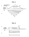
- FIGS. 4 to 6 illustrates shift patterns of the reference position 24.
- FIGS. 4(a) , 5(a), and 6(a) schematically illustrate shift patterns
- FIGS. 4(b) , 5(b), and 6(b) schematically illustrate worn states of a fixing member 100.
- the reference position 24 is shifted in accordance with a shift pattern in which the shift width of the reference position 24 is gradually reduced to a certain width as illustrated in FIG. 4(a) .
- the number of times an edge portion of the sheet 8 passes a given area of the fixing member 100 decreases at a portion closer to an edge of the given area compared to a middle portion of the given area.
- a worn portion 101 is formed in a substantially trapezoidal shape as illustrated in FIG. 4(b) . Accordingly, in this example, the boundary between the worn portion 101 and an unworn portion is less remarkable, and a narrow edge portion of the substantially-trapezoidal worn portion 101 is not so severely worn.
- formation of a step between the narrow edge and each oblique edge can be suppressed, preventing uneven fixing of a desired image.
- the reference position 24 is shifted in accordance with a shift pattern in which the shift width of the reference position 24 is gradually reduced to a certain width as illustrated in FIG. 5(a) .
- the number of times an edge portion of the sheet 8 passes a given area of the fixing member 100 decreases at a portion closer to an edge of the given area compared to a middle portion of the given area.
- a worn portion 102 is formed in a substantially triangle shape as illustrated in FIG. 5(b) .
- the boundary between the worn portion 101 and an unworn portion is less remarkable and, since the number of times the end portion of the sheet 8 passes the given area of the fixing member 100 increases at a portion around a peak of the substantially-triangular worn portion 102, results in relatively heavy wear near the peak.
- the reference position 24 is repeatedly shifted with a certain width.
- a worn portion 103 is formed in a substantially rectangular shape as illustrated in FIG. 6(b) .
- the degree of wear is suppressed as a whole although the boundary between the worn portion 103 and an unworn portion is relatively sharply defined compared to the above-described examples.
- the shift pattern in which the shift unit 40 is driven can be selected from among a plurality of different shift patterns, such as the above-described shift patterns, depending on the configuration of the image forming apparatus 1000 and the conditions under which it is used.
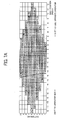
- FIGS. 7A and 7B illustrate the first shift pattern.
- FIG. 7A is a schematic diagram illustrating the first shift pattern
- FIG. 7B is a schematic diagram illustrating the number of printed sheets at each shift position.
- a worn portion is formed in a substantially trapezoidal shape as illustrated in FIG. 4(a) , and the first shift pattern includes a set of 10 patterns (pattern 1 to 10).
- pattern 1 to 10 In the first shift pattern, from a neutral position "0" of the reference position 24, the reference position 24 is shifted in positive and negative directions according to, for example, the following patterns 1 to 10.
- the negative direction indicates an operator side
- the positive direction indicates a side opposite the operator side.
- the drive control device performs the patterns 1 to 10 (cell Nos. 1 to 160) in turn.
- the drive control device returns to the pattern 1 and repeats the process from the pattern 1 to the pattern 10.
- FIG. 7B illustrates the number of stop operations and the number of printed sheets at each of the positions "-12" to "+12".
- the shift from one cell to another cell is carried out each time a certain number of sheets passes.
- the shift operation may be repeated, for example, at a certain time interval.
- the shift amount between adjacent points is set to 0.0847 mm, which corresponds to 300 dpi, a resolution of the sheet detector 17 in this example. It may be preferable that the minimum shift unit is smaller. However, since the degree of shift accuracy in this example is substantially ⁇ 0.1 mm and setting the shift amount to a value smaller than 0.0847 mm may be an excessive specification in terms of the degree of shift accuracy, the shift amount is set to 0.0847 mm as described above. In other words, since the shift amount of the shift unit 40 varies in a range of ⁇ 0.1 mm, the minimum shift amount is set to 0.0847 mm in this example.
- the maximum shift amount of the shift unit 40 is ⁇ 1.016 mm (0.0847 mm X 12 dots) at the pattern 6.
- the maximum shift amount in this example is set to ⁇ 1 mm taking mechanical limitations into account. Since the movable range of the shift unit 40 is ⁇ 5 mm, ⁇ 4 mm is allocated to correction for a sheet-feed displacement and the remaining ⁇ 1 mm is used for cyclical shift.
- the maximum number of steps of the shift unit 40 is 25 (from the positions "-12” to “+12" including the position "0").
- the total number of 10 patterns is selected so that a worn portion of the fixing member is formed in a substantially trapezoidal shape.
- the total number of patterns and the number of shifts can be varied.
- a position-information storage device is provided to store a shift position of the reference position 24 in a shift pattern, a number code of the shift pattern, and the number of sheets printed at the shift position.
- the reference position 24 is determined based on the position information. For example, when the power is turned off at the position "+2" (cell No. 28) in the shift pattern 3 and then turned on again, the shift of the reference position 24 is restarted from the cell No. 28.
- the degree of wear on a fixing member can be continuously managed, effectively increasing the service life of the fixing member.
- FIG. 8 is a graph showing results of a test that the inventor performed to evaluate the effectiveness of the shift patterns, in which the total number of sheets was set to 9,000, the total number of patterns was set to three, and the number of sheets passing each cell was set to 200.
- the evaluation test was performed under the above-described conditions, no fixing failure was found and image formation performance was excellent.
- the boundary between a worn portion and an unworn portion is less remarkable, a narrow-edge portion of the worn portion of a substantially trapezoidal shape is less worn, and no remarkable step arises between a narrow edge and each oblique edge of the substantially-trapezoidal worn portion, preventing uneven fixing of an image on the sheet.
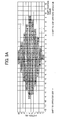
- FIGS. 9A and 9B illustrate the second shift pattern.
- FIG. 9A is a graph illustrating the second shift pattern
- FIG. 9B is a graph illustrating the number of printed sheets at each shift position.
- the second shift pattern includes a set of 10 patterns (Patterns 1 to 10).
- the reference position 24 is shifted in the positive and negative directions according to, for example, the following patterns 1 to 10.
- the drive control device performs the patterns 1 to 10 (cell Nos. 1 to 100) in turn.
- the drive control device returns to the pattern 1 and repeats the process from the pattern 1 to the pattern 10.
- FIG. 9B illustrates the number of stop operations and the number of printed sheets at each of the positions "-9" to "+9".
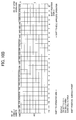
- FIGS. 10A and 10B illustrate the third shift pattern.
- FIG. 10A is a graph illustrating the third shift pattern
- FIG. 10B is a graph illustrating the number of printed sheets at each shift position.
- the third shift pattern includes a set of 10 patterns (Patterns 1 to 10).
- the reference position 24 is shifted in the positive and negative directions according to, for example, the following patterns 1 to 10.
- the drive control device performs the patterns 1 to 10 (cell Nos. 1 to 250) in turn.
- the drive control device returns to the pattern 1 and repeats the process from the pattern 1 to the pattern 10.
- the recording-medium positioning device 200 and the image forming apparatus 1000 can prevent a fixing member from being unevenly worn by edges of a recording medium. As a result, degradation in image quality at a certain position of the fixing member can be suppressed, allowing excellent image formation.
Landscapes
- Physics & Mathematics (AREA)
- General Physics & Mathematics (AREA)
- Control Or Security For Electrophotography (AREA)
- Fixing For Electrophotography (AREA)
- Color Electrophotography (AREA)
- Registering Or Overturning Sheets (AREA)
Applications Claiming Priority (1)
| Application Number | Priority Date | Filing Date | Title |
|---|---|---|---|
| JP2008161243A JP2010002653A (ja) | 2008-06-20 | 2008-06-20 | 記録媒体位置決め装置及び画像形成装置 |
Publications (2)
| Publication Number | Publication Date |
|---|---|
| EP2136261A2 true EP2136261A2 (de) | 2009-12-23 |
| EP2136261A3 EP2136261A3 (de) | 2013-07-10 |
Family
ID=41057006
Family Applications (1)
| Application Number | Title | Priority Date | Filing Date |
|---|---|---|---|
| EP09251577.4A Withdrawn EP2136261A3 (de) | 2008-06-20 | 2009-06-17 | Aufzeichnungsmedium-Positionierungsvorrichtung und Bilderzeugungsvorrichtung mit der Vorrichtung |
Country Status (3)
| Country | Link |
|---|---|
| US (1) | US8494433B2 (de) |
| EP (1) | EP2136261A3 (de) |
| JP (1) | JP2010002653A (de) |
Cited By (1)
| Publication number | Priority date | Publication date | Assignee | Title |
|---|---|---|---|---|
| CN103163762A (zh) * | 2011-12-09 | 2013-06-19 | 柯尼卡美能达商用科技株式会社 | 图像形成装置 |
Families Citing this family (9)
| Publication number | Priority date | Publication date | Assignee | Title |
|---|---|---|---|---|
| JP5445251B2 (ja) * | 2010-03-16 | 2014-03-19 | 株式会社リコー | 画像形成装置 |
| JP5743577B2 (ja) * | 2011-02-03 | 2015-07-01 | キヤノン株式会社 | 像加熱装置 |
| JP5691806B2 (ja) * | 2011-04-28 | 2015-04-01 | コニカミノルタ株式会社 | 画像形成装置 |
| JP5522131B2 (ja) * | 2011-08-02 | 2014-06-18 | コニカミノルタ株式会社 | 画像形成装置および画像形成システム |
| JP5423767B2 (ja) * | 2011-10-27 | 2014-02-19 | コニカミノルタ株式会社 | 画像形成装置 |
| JP2013238752A (ja) * | 2012-05-16 | 2013-11-28 | Konica Minolta Inc | 画像形成装置 |
| JP6425128B2 (ja) | 2014-11-28 | 2018-11-21 | 株式会社リコー | 用紙搬送装置及び画像形成装置 |
| US10197961B2 (en) * | 2016-02-16 | 2019-02-05 | Canon Kabushiki Kaisha | Image forming apparatus |
| JP2020095163A (ja) * | 2018-12-13 | 2020-06-18 | 京セラドキュメントソリューションズ株式会社 | 画像形成装置 |
Citations (2)
| Publication number | Priority date | Publication date | Assignee | Title |
|---|---|---|---|---|
| JP2003131525A (ja) | 2001-10-26 | 2003-05-09 | Fuji Xerox Co Ltd | 画像形成装置 |
| EP1870358A1 (de) | 2006-06-21 | 2007-12-26 | Ricoh Company, Ltd. | Papierfördergerät und Bilderzeugungsgerät mit dem Papierfördergerät |
Family Cites Families (10)
| Publication number | Priority date | Publication date | Assignee | Title |
|---|---|---|---|---|
| JP2000092292A (ja) * | 1998-09-16 | 2000-03-31 | Nec Corp | イメージセンサ及び画像読取装置 |
| JP2000221834A (ja) | 1999-02-03 | 2000-08-11 | Minolta Co Ltd | 定着装置 |
| JP2000221821A (ja) | 1999-02-03 | 2000-08-11 | Minolta Co Ltd | 定着装置 |
| JP2001354346A (ja) * | 2000-06-12 | 2001-12-25 | Sharp Corp | 画像形成装置の用紙搬送機構 |
| JP2003263090A (ja) * | 2002-01-07 | 2003-09-19 | Ricoh Co Ltd | 画像形成装置及び給送装置 |
| JP2005134795A (ja) | 2003-10-31 | 2005-05-26 | Ricoh Co Ltd | 定着装置 |
| JP2006072246A (ja) | 2004-09-06 | 2006-03-16 | Fuji Xerox Co Ltd | 画像形成装置 |
| JP4469321B2 (ja) * | 2005-10-14 | 2010-05-26 | 株式会社リコー | 画像形成装置 |
| JP4730390B2 (ja) * | 2008-04-11 | 2011-07-20 | 富士ゼロックス株式会社 | 記録材移動装置及び画像形成装置 |
| CN101910958B (zh) * | 2008-08-18 | 2012-06-06 | 柯尼卡美能达商用科技株式会社 | 图像形成装置 |
-
2008
- 2008-06-20 JP JP2008161243A patent/JP2010002653A/ja active Pending
-
2009
- 2009-06-17 EP EP09251577.4A patent/EP2136261A3/de not_active Withdrawn
- 2009-06-19 US US12/457,738 patent/US8494433B2/en not_active Expired - Fee Related
Patent Citations (2)
| Publication number | Priority date | Publication date | Assignee | Title |
|---|---|---|---|---|
| JP2003131525A (ja) | 2001-10-26 | 2003-05-09 | Fuji Xerox Co Ltd | 画像形成装置 |
| EP1870358A1 (de) | 2006-06-21 | 2007-12-26 | Ricoh Company, Ltd. | Papierfördergerät und Bilderzeugungsgerät mit dem Papierfördergerät |
Cited By (1)
| Publication number | Priority date | Publication date | Assignee | Title |
|---|---|---|---|---|
| CN103163762A (zh) * | 2011-12-09 | 2013-06-19 | 柯尼卡美能达商用科技株式会社 | 图像形成装置 |
Also Published As
| Publication number | Publication date |
|---|---|
| EP2136261A3 (de) | 2013-07-10 |
| US8494433B2 (en) | 2013-07-23 |
| US20090317114A1 (en) | 2009-12-24 |
| JP2010002653A (ja) | 2010-01-07 |
Similar Documents
| Publication | Publication Date | Title |
|---|---|---|
| US8494433B2 (en) | Recording-medium positioning device and image forming apparatus employing the device | |
| US8249468B2 (en) | Image forming apparatus | |
| US8135320B2 (en) | Image forming apparatus | |
| US9352916B2 (en) | Sheet conveying device, sheet discharging device, and image forming apparatus | |
| US9908727B2 (en) | Sheet conveyance apparatus and image forming apparatus | |
| US20140086643A1 (en) | Image forming apparatus | |
| JP2022112901A (ja) | 転写ユニットおよびそれを備えた画像形成装置 | |
| JP2022129622A (ja) | 転写ユニットおよびそれを備えた画像形成装置 | |
| US10126688B2 (en) | Transfer unit and image forming apparatus including same | |
| JP2023022929A (ja) | 転写ユニットおよびそれを備えた画像形成装置 | |
| JP2010215374A (ja) | 画像形成装置 | |
| JP2022112903A (ja) | 転写ユニットおよびそれを備えた画像形成装置 | |
| JP2022112902A (ja) | 転写ユニットおよびそれを備えた画像形成装置 | |
| US7556260B2 (en) | Image forming apparatus | |
| US8909112B2 (en) | Image forming apparatus having support members with predetermined electric potentials | |
| JP4213854B2 (ja) | シート搬送装置および画像形成装置 | |
| US20080112744A1 (en) | Sheet conveying apparatus and image forming apparatus | |
| US6418294B2 (en) | Color image forming apparatus with intermediate transfer member length a non-integral multiple of image pitch | |
| CN205708985U (zh) | 供纸辊、供纸输送装置和图像形成装置 | |
| US9244419B2 (en) | Sheet compression apparatus and image forming apparatus | |
| US9637336B2 (en) | Sheet conveying apparatus and image forming apparatus | |
| JP4447700B2 (ja) | 画像形成装置 | |
| US10221030B2 (en) | Sheet conveying apparatus and image forming apparatus | |
| JP5162815B2 (ja) | 画像形成装置 | |
| JP4534878B2 (ja) | シート供給装置及び画像形成装置 |
Legal Events
| Date | Code | Title | Description |
|---|---|---|---|
| PUAI | Public reference made under article 153(3) epc to a published international application that has entered the european phase |
Free format text: ORIGINAL CODE: 0009012 |
|
| AK | Designated contracting states |
Kind code of ref document: A2 Designated state(s): AT BE BG CH CY CZ DE DK EE ES FI FR GB GR HR HU IE IS IT LI LT LU LV MC MK MT NL NO PL PT RO SE SI SK TR |
|
| PUAL | Search report despatched |
Free format text: ORIGINAL CODE: 0009013 |
|
| AK | Designated contracting states |
Kind code of ref document: A3 Designated state(s): AT BE BG CH CY CZ DE DK EE ES FI FR GB GR HR HU IE IS IT LI LT LU LV MC MK MT NL NO PL PT RO SE SI SK TR |
|
| AX | Request for extension of the european patent |
Extension state: AL BA RS |
|
| RIC1 | Information provided on ipc code assigned before grant |
Ipc: G03G 15/00 20060101AFI20130606BHEP |
|
| 17P | Request for examination filed |
Effective date: 20131116 |
|
| RBV | Designated contracting states (corrected) |
Designated state(s): AT BE BG CH CY CZ DE DK EE ES FI FR GB GR HR HU IE IS IT LI LT LU LV MC MK MT NL NO PL PT RO SE SI SK TR |
|
| STAA | Information on the status of an ep patent application or granted ep patent |
Free format text: STATUS: EXAMINATION IS IN PROGRESS |
|
| 17Q | First examination report despatched |
Effective date: 20171121 |
|
| STAA | Information on the status of an ep patent application or granted ep patent |
Free format text: STATUS: THE APPLICATION IS DEEMED TO BE WITHDRAWN |
|
| 18D | Application deemed to be withdrawn |
Effective date: 20190809 |