EP2136253B1 - Trägerkernmaterial für ein elektrofotogrfisches entwicklungsmittel, verfahren zur herstellung des trägerkernmaterials, träger für ein elektrofotografisches entwicklungsmittel und elektrofotografisches entwicklungsmittel - Google Patents
Trägerkernmaterial für ein elektrofotogrfisches entwicklungsmittel, verfahren zur herstellung des trägerkernmaterials, träger für ein elektrofotografisches entwicklungsmittel und elektrofotografisches entwicklungsmittel Download PDFInfo
- Publication number
- EP2136253B1 EP2136253B1 EP08740128.7A EP08740128A EP2136253B1 EP 2136253 B1 EP2136253 B1 EP 2136253B1 EP 08740128 A EP08740128 A EP 08740128A EP 2136253 B1 EP2136253 B1 EP 2136253B1
- Authority
- EP
- European Patent Office
- Prior art keywords
- carrier
- core material
- electrophotographic developer
- particle size
- powders
- Prior art date
- Legal status (The legal status is an assumption and is not a legal conclusion. Google has not performed a legal analysis and makes no representation as to the accuracy of the status listed.)
- Active
Links
- 239000011162 core material Substances 0.000 title claims description 56
- 238000000034 method Methods 0.000 title claims description 15
- 239000002245 particle Substances 0.000 claims description 144
- 239000002994 raw material Substances 0.000 claims description 49
- 239000000843 powder Substances 0.000 claims description 48
- 238000005245 sintering Methods 0.000 claims description 21
- 238000001144 powder X-ray diffraction data Methods 0.000 claims description 16
- 238000004519 manufacturing process Methods 0.000 claims description 15
- 238000010298 pulverizing process Methods 0.000 claims description 10
- 239000002002 slurry Substances 0.000 claims description 10
- 239000000463 material Substances 0.000 claims description 9
- 230000001186 cumulative effect Effects 0.000 claims description 6
- 239000011347 resin Substances 0.000 claims description 6
- 229920005989 resin Polymers 0.000 claims description 6
- 238000003756 stirring Methods 0.000 claims description 3
- 238000001035 drying Methods 0.000 claims description 2
- 239000010419 fine particle Substances 0.000 claims description 2
- 239000000203 mixture Substances 0.000 description 35
- 238000002441 X-ray diffraction Methods 0.000 description 30
- 230000000052 comparative effect Effects 0.000 description 26
- 238000002156 mixing Methods 0.000 description 19
- QVGXLLKOCUKJST-UHFFFAOYSA-N atomic oxygen Chemical compound [O] QVGXLLKOCUKJST-UHFFFAOYSA-N 0.000 description 9
- 239000001301 oxygen Substances 0.000 description 9
- 229910052760 oxygen Inorganic materials 0.000 description 9
- 238000011161 development Methods 0.000 description 8
- 238000012545 processing Methods 0.000 description 8
- 229910000859 α-Fe Inorganic materials 0.000 description 8
- JEIPFZHSYJVQDO-UHFFFAOYSA-N iron(III) oxide Inorganic materials O=[Fe]O[Fe]=O JEIPFZHSYJVQDO-UHFFFAOYSA-N 0.000 description 7
- 239000006247 magnetic powder Substances 0.000 description 7
- AMWRITDGCCNYAT-UHFFFAOYSA-L manganese oxide Inorganic materials [Mn].O[Mn]=O.O[Mn]=O AMWRITDGCCNYAT-UHFFFAOYSA-L 0.000 description 7
- 239000000395 magnesium oxide Substances 0.000 description 6
- 238000005259 measurement Methods 0.000 description 6
- 230000003647 oxidation Effects 0.000 description 6
- 238000007254 oxidation reaction Methods 0.000 description 6
- 239000002270 dispersing agent Substances 0.000 description 4
- 108091008695 photoreceptors Proteins 0.000 description 4
- 238000012216 screening Methods 0.000 description 4
- 239000000126 substance Substances 0.000 description 4
- CPLXHLVBOLITMK-UHFFFAOYSA-N Magnesium oxide Chemical compound [Mg]=O CPLXHLVBOLITMK-UHFFFAOYSA-N 0.000 description 3
- 239000011230 binding agent Substances 0.000 description 3
- 229910052751 metal Inorganic materials 0.000 description 3
- 239000002184 metal Substances 0.000 description 3
- 150000002739 metals Chemical class 0.000 description 3
- QGZKDVFQNNGYKY-UHFFFAOYSA-O Ammonium Chemical compound [NH4+] QGZKDVFQNNGYKY-UHFFFAOYSA-O 0.000 description 2
- 229910001035 Soft ferrite Inorganic materials 0.000 description 2
- 238000004364 calculation method Methods 0.000 description 2
- -1 carbonate compound Chemical class 0.000 description 2
- 230000000694 effects Effects 0.000 description 2
- SZVJSHCCFOBDDC-UHFFFAOYSA-N ferrosoferric oxide Chemical compound O=[Fe]O[Fe]O[Fe]=O SZVJSHCCFOBDDC-UHFFFAOYSA-N 0.000 description 2
- 238000005469 granulation Methods 0.000 description 2
- 230000003179 granulation Effects 0.000 description 2
- 150000002500 ions Chemical class 0.000 description 2
- 230000005415 magnetization Effects 0.000 description 2
- NUJOXMJBOLGQSY-UHFFFAOYSA-N manganese dioxide Chemical compound O=[Mn]=O NUJOXMJBOLGQSY-UHFFFAOYSA-N 0.000 description 2
- 229920001296 polysiloxane Polymers 0.000 description 2
- 238000000634 powder X-ray diffraction Methods 0.000 description 2
- 239000007921 spray Substances 0.000 description 2
- 238000012546 transfer Methods 0.000 description 2
- XLYOFNOQVPJJNP-UHFFFAOYSA-N water Substances O XLYOFNOQVPJJNP-UHFFFAOYSA-N 0.000 description 2
- QIVUCLWGARAQIO-OLIXTKCUSA-N (3s)-n-[(3s,5s,6r)-6-methyl-2-oxo-1-(2,2,2-trifluoroethyl)-5-(2,3,6-trifluorophenyl)piperidin-3-yl]-2-oxospiro[1h-pyrrolo[2,3-b]pyridine-3,6'-5,7-dihydrocyclopenta[b]pyridine]-3'-carboxamide Chemical compound C1([C@H]2[C@H](N(C(=O)[C@@H](NC(=O)C=3C=C4C[C@]5(CC4=NC=3)C3=CC=CN=C3NC5=O)C2)CC(F)(F)F)C)=C(F)C=CC(F)=C1F QIVUCLWGARAQIO-OLIXTKCUSA-N 0.000 description 1
- IJGRMHOSHXDMSA-UHFFFAOYSA-N Atomic nitrogen Chemical compound N#N IJGRMHOSHXDMSA-UHFFFAOYSA-N 0.000 description 1
- OAICVXFJPJFONN-UHFFFAOYSA-N Phosphorus Chemical compound [P] OAICVXFJPJFONN-UHFFFAOYSA-N 0.000 description 1
- 239000004372 Polyvinyl alcohol Substances 0.000 description 1
- 230000002159 abnormal effect Effects 0.000 description 1
- 230000005856 abnormality Effects 0.000 description 1
- 230000001133 acceleration Effects 0.000 description 1
- KGBXLFKZBHKPEV-UHFFFAOYSA-N boric acid Chemical compound OB(O)O KGBXLFKZBHKPEV-UHFFFAOYSA-N 0.000 description 1
- 239000004327 boric acid Substances 0.000 description 1
- 239000000969 carrier Substances 0.000 description 1
- 238000000576 coating method Methods 0.000 description 1
- 229910017052 cobalt Inorganic materials 0.000 description 1
- 239000010941 cobalt Substances 0.000 description 1
- GUTLYIVDDKVIGB-UHFFFAOYSA-N cobalt atom Chemical compound [Co] GUTLYIVDDKVIGB-UHFFFAOYSA-N 0.000 description 1
- 238000007796 conventional method Methods 0.000 description 1
- 229910001873 dinitrogen Inorganic materials 0.000 description 1
- 239000007789 gas Substances 0.000 description 1
- 230000010354 integration Effects 0.000 description 1
- 239000000314 lubricant Substances 0.000 description 1
- 239000011777 magnesium Substances 0.000 description 1
- 239000001095 magnesium carbonate Substances 0.000 description 1
- ZLNQQNXFFQJAID-UHFFFAOYSA-L magnesium carbonate Chemical compound [Mg+2].[O-]C([O-])=O ZLNQQNXFFQJAID-UHFFFAOYSA-L 0.000 description 1
- 229910000021 magnesium carbonate Inorganic materials 0.000 description 1
- VTHJTEIRLNZDEV-UHFFFAOYSA-L magnesium dihydroxide Chemical compound [OH-].[OH-].[Mg+2] VTHJTEIRLNZDEV-UHFFFAOYSA-L 0.000 description 1
- 239000000347 magnesium hydroxide Substances 0.000 description 1
- 229910001862 magnesium hydroxide Inorganic materials 0.000 description 1
- 239000011656 manganese carbonate Substances 0.000 description 1
- 229910000016 manganese(II) carbonate Inorganic materials 0.000 description 1
- GEYXPJBPASPPLI-UHFFFAOYSA-N manganese(III) oxide Inorganic materials O=[Mn]O[Mn]=O GEYXPJBPASPPLI-UHFFFAOYSA-N 0.000 description 1
- 238000000691 measurement method Methods 0.000 description 1
- 239000011268 mixed slurry Substances 0.000 description 1
- XULSCZPZVQIMFM-IPZQJPLYSA-N odevixibat Chemical compound C12=CC(SC)=C(OCC(=O)N[C@@H](C(=O)N[C@@H](CC)C(O)=O)C=3C=CC(O)=CC=3)C=C2S(=O)(=O)NC(CCCC)(CCCC)CN1C1=CC=CC=C1 XULSCZPZVQIMFM-IPZQJPLYSA-N 0.000 description 1
- 229910052698 phosphorus Inorganic materials 0.000 description 1
- 239000011574 phosphorus Substances 0.000 description 1
- 229920002451 polyvinyl alcohol Polymers 0.000 description 1
- 230000001737 promoting effect Effects 0.000 description 1
- 230000000630 rising effect Effects 0.000 description 1
- 239000007787 solid Substances 0.000 description 1
- 238000001694 spray drying Methods 0.000 description 1
- 239000011800 void material Substances 0.000 description 1
Images

Classifications
-
- G—PHYSICS
- G03—PHOTOGRAPHY; CINEMATOGRAPHY; ANALOGOUS TECHNIQUES USING WAVES OTHER THAN OPTICAL WAVES; ELECTROGRAPHY; HOLOGRAPHY
- G03G—ELECTROGRAPHY; ELECTROPHOTOGRAPHY; MAGNETOGRAPHY
- G03G9/00—Developers
- G03G9/08—Developers with toner particles
- G03G9/10—Developers with toner particles characterised by carrier particles
- G03G9/113—Developers with toner particles characterised by carrier particles having coatings applied thereto
-
- G—PHYSICS
- G03—PHOTOGRAPHY; CINEMATOGRAPHY; ANALOGOUS TECHNIQUES USING WAVES OTHER THAN OPTICAL WAVES; ELECTROGRAPHY; HOLOGRAPHY
- G03G—ELECTROGRAPHY; ELECTROPHOTOGRAPHY; MAGNETOGRAPHY
- G03G9/00—Developers
- G03G9/08—Developers with toner particles
- G03G9/10—Developers with toner particles characterised by carrier particles
- G03G9/107—Developers with toner particles characterised by carrier particles having magnetic components
- G03G9/1087—Specified elemental magnetic metal or alloy, e.g. alnico comprising iron, nickel, cobalt, and aluminum, or permalloy comprising iron and nickel
-
- G—PHYSICS
- G03—PHOTOGRAPHY; CINEMATOGRAPHY; ANALOGOUS TECHNIQUES USING WAVES OTHER THAN OPTICAL WAVES; ELECTROGRAPHY; HOLOGRAPHY
- G03G—ELECTROGRAPHY; ELECTROPHOTOGRAPHY; MAGNETOGRAPHY
- G03G9/00—Developers
- G03G9/08—Developers with toner particles
- G03G9/10—Developers with toner particles characterised by carrier particles
- G03G9/107—Developers with toner particles characterised by carrier particles having magnetic components
- G03G9/108—Ferrite carrier, e.g. magnetite
- G03G9/1085—Ferrite carrier, e.g. magnetite with non-ferrous metal oxide, e.g. MgO-Fe2O3
-
- G—PHYSICS
- G03—PHOTOGRAPHY; CINEMATOGRAPHY; ANALOGOUS TECHNIQUES USING WAVES OTHER THAN OPTICAL WAVES; ELECTROGRAPHY; HOLOGRAPHY
- G03G—ELECTROGRAPHY; ELECTROPHOTOGRAPHY; MAGNETOGRAPHY
- G03G9/00—Developers
- G03G9/08—Developers with toner particles
- G03G9/10—Developers with toner particles characterised by carrier particles
- G03G9/113—Developers with toner particles characterised by carrier particles having coatings applied thereto
- G03G9/1131—Coating methods; Structure of coatings
-
- G—PHYSICS
- G03—PHOTOGRAPHY; CINEMATOGRAPHY; ANALOGOUS TECHNIQUES USING WAVES OTHER THAN OPTICAL WAVES; ELECTROGRAPHY; HOLOGRAPHY
- G03G—ELECTROGRAPHY; ELECTROPHOTOGRAPHY; MAGNETOGRAPHY
- G03G9/00—Developers
- G03G9/08—Developers with toner particles
- G03G9/10—Developers with toner particles characterised by carrier particles
- G03G9/113—Developers with toner particles characterised by carrier particles having coatings applied thereto
- G03G9/1132—Macromolecular components of coatings
- G03G9/1135—Macromolecular components of coatings obtained otherwise than by reactions only involving carbon-to-carbon unsaturated bonds
- G03G9/1136—Macromolecular components of coatings obtained otherwise than by reactions only involving carbon-to-carbon unsaturated bonds containing silicon atoms
Definitions
- the present invention relates to a carrier core material for electrophotographic developer used in a carrier for two-component electrophotographic developer used as a mixture with toner in a two-component electrophotographic developer and a manufacturing method of the same, a carrier for electrophotographic developer, and an electrophotographic developer.
- carrier adhesion is a phenomenon in which a carrier used in an electrophotographic developer scatters during the electrophotographic development process and adheres to the photoreceptor or other development apparatus.
- the carrier In a development apparatus, the carrier is prevented from scattering by an existence of a magnetic force and an electrostatic force to let the carrier hold on the development sleeve against a centrifugal force, added to the carrier by rotation of the development sleeve.
- the centrifugal force obtained by the rotation of the development sleeve is greater than the holding force. Consequently, a phenomenon (carrier adhesion) occurs in which the carrier scatters from the magnetic brush and adheres to the photoreceptor.
- the carrier adhered to the photoreceptor sometimes unfavorably reaches the transfer unit. In a state that the carrier is adhered to the photoreceptor, a toner image around the carrier is not transferred to transfer paper, thereby causing image abnormality.
- carrier scattering is generally considered to occur mainly by the carrier with particle size smaller than 22 ⁇ m. Therefore, by taking a measure such that the content of the carrier having particle size smaller than 22 ⁇ m is set to be less than 1 wt% of the electrophotographic developer, it can be so considered that the carrier scattering can be prevented.
- Patent Document 1 proposes a carrier, with a volume average particle size of core material particles set to be 25 ⁇ m to 45 ⁇ m, an average void diameter set to be 10 ⁇ m to 20 ⁇ m, proportion of particles having 22 ⁇ m or smaller particle size set to be less than 1%, magnetization in a magnetic field 7.958x10 4 (1000 Oe) set to be 67 - 88 A.m 2 / Kg (emu/g) and a difference between magnetization of scattered materials and that of a main body set to be 10 A.m2/kg (emu/g) or smaller.
- Patent Document 1 Japanese Patent Laid Open Publication No. 2002-296846
- an object of the present invention is to provide a carrier for electrophotographic developer capable of realizing a high image quality and full colorization and simultaneously capable of reducing scattering, and a manufacturing method of the same, and the electrophotographic developer including this carrier.
- a second knowledge is that when the magnetic susceptibility of the carrier is high beyond a prescribed value, a magnetic brush formed in a developing device becomes excessively hard, and therefore excellent image characteristics can not be obtained.
- the holding force among particles around the low magnetic susceptibility particles becomes locally weak in a magnetic brush formed by the carrier. Because the holding force among carriers (particles) becomes weak, carrier scattering occurs in this weakened portion. Therefore, the amount of carrier scattering increases in proportion to the increase in the existence ratio of the low magnetic susceptibility particles contained in the carrier.
- magnetic susceptibility described in the present invention is expressed, unless otherwise specified, by ⁇ 1000 (unit: A.m2/kg (emu/g)) which is a magnetic susceptibility in an external magnetic field 7.958x10 4 A/m (1000 Oe) and a low magnetic susceptibility particles are particles satisfying ⁇ 1000 ⁇ 15 A.m2/kg (emu/g)
- the inventors of the present invention perform study on the reduction of the existence ratio of the low magnetic susceptibility particles in the carrier, to prevent the carrier from scattering.
- the existence ratio of the low magnetic susceptibility particles in the carrier is extremely low, such as several hundred ppm or less, even in cases where serious carrier scattering occurs. Therefore, it is found that the existence ratio of the low magnetic susceptibility particles cannot be measured correctly by ordinary screening methods such as a magnetic screening method.
- the inventors of the present invention focus on a half-value width of a peak in a carrier's powder X-ray diffraction (XRD) pattern and obtains a knowledge that as the half-value width of the carrier becomes narrower, the existence ratio of the low magnetic susceptibility particles becomes lower, and thus, carrier scattering can be prevented.
- XRD X-ray diffraction
- the cause for the existence of the low magnetic susceptibility particles in the carrier is the occurrence of the particle having a composition significantly different from that of a general population of the carrier due to some reason caused during a manufacturing process.
- This particle has the same crystalline structure as that of the general population of the carrier but has a different composition. Therefore, a lattice constant is changed.
- the powder XRD pattern of the low magnetic susceptibility particles is similar to the powder XRD pattern of the general population of the carrier, the peak position is slightly deviated. Therefore, the powder XRD pattern of the carrier, in which low magnetic susceptibility particles are mixed, is formed in a pattern having a broader peak in which a plurality of slightly deviated XRD patterns are overlapped on one another.
- the existence ratio in the carrier of the low magnetic susceptibility particles is several hundreds ppm or less and is extremely small, even when serious carrier scattering occurs. Therefore, in the normal screening method such as a magnetic screening method, it is found that the existence ratio of the low magnetic susceptibility particles can not be accurately measured.
- the inventors of the present invention focus on a half-value width of the peak in the powder X-ray diffraction (XRD) pattern and obtain a knowledge that as the half-value width of the carrier becomes narrower, the existence ratio of the low magnetic susceptibility particles becomes lower, and thus, carrier scattering can be prevented.
- XRD powder X-ray diffraction
- the cause for the existence of the low magnetic susceptibility particles in the carrier is the occurrence of the particle having a composition significantly different from that of the general population of the carrier due to some reason caused during the manufacturing process.
- This particle has the same crystalline structure as that of the general population of the carrier but has a different composition. Therefore, the lattice constant is changed.
- the powder XRD pattern of the low magnetic susceptibility particle is similar to the powder XRD pattern of the general population of the carrier, the peak position is slightly deviated.
- the powder XRD pattern of the carrier in which low magnetic susceptibility particles are mixed, is formed in a pattern having a broader peak in which a plurality of slightly deviated XRD patterns are overlapped on one another.
- the peak width in the XRD pattern of the carrier becomes narrower, the existence ratio of the low magnetic susceptibility particles becomes small.
- the carrier with the carrier scattering suppressed, can be defined by using the half-value width of the peak in the powder XRD pattern, and further a manufacturing method is found, capable of manufacturing the magnetic powders, wherein the half-value width of the peak in the powder XRD pattern is defined.
- the inventors of the present invention make a strenuous effort to study on solving the problem that excellent image characteristics can not be obtained, because the aforementioned magnetic brush is excessively hard.
- the inventors achieve a point that the magnetic susceptibility of the carrier in the external magnetic field 7.958x10 4 A/m (1000 Oe) may be set to 65 A.m 2 /kg (65 emu/g) or less.
- first means for solving the problem provides a carrier core material for electrophotographic developer expressed by a general formula Mg x Mn (1-x) Fe y O 4 (where 0 ⁇ x ⁇ 1, and 1.6 ⁇ y ⁇ 2.4), wherein a half-value width B of a peak having a maximum intensity in a powder XRD pattern satisfies B ⁇ 0.180 (degree).
- Second means provides the carrier core material for electrophotographic developer described in the first means, wherein a general formula is expressed by Mg x Mn (1-x) Fe y O 4 (where 0 ⁇ x ⁇ 0.8, and 1.6 ⁇ y ⁇ 2.4).
- Third means provides the carrier for electrophotographic developer according to the first means or the second means, wherein magnetic susceptibility ⁇ 1000 in an external magnetic field 7.958x10 4 A/m (1000 Oe) satisfies 15 A.m2/kg (15 emu/g) ⁇ ⁇ 1000 ⁇ 65 A.m 2 /kg (65 emu/g)
- Fourth means provides the carrier for electrophotographic developer according to any one of the first to third means, wherein an average particle size is 10 ⁇ m or more and 80 ⁇ m or less.
- Fifth means provides a method for manufacturing a carrier core material for electrophotographic developer including the steps of:
- Sixth means provides the carrier for electrophotographic developer, wherein the carrier core material according to any one of the first to fourth means is coated with resin.
- Seventh means provides an electrophotographic developer, including the carrier for electrophotographic developer according to the sixth means and toner.
- a carrier for electrophotographic developer and an electrophotographic developer capable of significantly reducing scattering of a carrier in a developing machine when used as an electrophotographic developer for copiers, printers,
- a carrier core material for electrophotographic developer (2) a method for manufacturing a carrier core material for electrophotographic developer, (3) a carrier for electrophotographic developer, and (4) an electrophotographic developer.
- Carrier core material for electrophotographic developer 1. Carrier core material for electrophotographic developer
- Mg x Mn (1-x) Fe y O 4 (satisfying 0 ⁇ x ⁇ 1, 1.6 ⁇ y ⁇ 2.4), and further preferably (0 ⁇ x ⁇ 0.8, 1.6 ⁇ y ⁇ 2.4), being soft ferrite, is used as a substance, becoming the carrier core material constituting the carrier of the present invention.
- the substance expressed by the aforementioned composition formula makes it possible to have the magnetic susceptibility of 65 A.m 2 / kg (65 emu/g) or less of the carrier in the external magnetic field 7.958x10 4 A/m (1000 Oe) without controlling the oxygen concentration of the atmosphere by adjusting values of x, y, or without using the means involving the generation of characteristic variation of the particles such as lowering the sintering temperature, and further makes it possible to adjust powder characteristics such as apparent densities or fluidity.
- the magnetic phase expressed by this composition formula has a high stability even in a state of high oxygen concentration (for example, in an atmospheric air), and the generation of the low magnetic susceptibility particles due to excess oxidation can be suppressed, in the step of sintering.
- the carrier core material for electrophotographic developer according to the present invention has a half-value width B of the maximum peak of the substance, becoming the core material, satisfying B ⁇ 0.180 (degree) in the powder XRD pattern. This shows that, as described above, the narrower the half-value width of the material is, the less the existence ratio of the low magnetic susceptibility particles are. Further, when the value of B satisfies this relation, the carrier scattering is extremely lessened.
- the average particle size is preferably set to be 10 ⁇ m or more and 80 ⁇ m or less. This is because when the particle size is in this range or more, the image characteristics are deteriorated, and reversely when the particle size is too small, a magnetic force per one particle is lowered and the carrier scattering can be hardly suppressed.
- classification processing is performed by shifter, etc, during or after the manufacturing step, so as to have the aforementioned particle size distribution.
- the magnetic powders used as the carrier core material for electrophotographic developer are manufactured through the steps of mixing powders that become raw materials, then adding binder, etc, thereto, and granulating the powders up to a proper particle size, and thereafter obtaining a magnetic phase by sintering.
- the inventors of the present invention obtains a knowledge that it is effective that powders, becoming raw materials, are made finer in advance, and these raw material powders are sufficiently mixed.
- the generation of low magnetic susceptibility particles can be prevented by sufficiently mixing the raw material particles in the mixing and granulating process to thereby homogenize the composition of each particle, as an effect of making raw material powders finer and as an effect of sufficiently mixing the raw material powders.
- a simple substance of a constitution of the magnetic phase, being a target, or each kind of oxide or carbonate compound is used as the raw materials.
- metals Fe, Fe 3 O 4 , Fe 2 O 3 are suitably used as a Fe supply source
- metals Mn, MnO 2 , Mn 2 O 3 , Mn 3 O 4 , and MnCO 3 are suitably used as a Mn supply source
- metals Mg, MgO, MgCO 3 , and Mg(OH) 2 are suitably used as a Mg supply source.
- Each raw material is weighed and mixed, so that a mixing ratio of Fe, Mn, and Mg after sintering reaches a target composition.
- the particle of each raw material is made finer so that the average particle size is set to be 1.0 ⁇ m or less in a stage of not being granulated, such as a dry state.
- the value of D90 is desired to be 1.0 ⁇ m or less, when the particle size at cumulative curve of 90% is expressed by D90.
- the particle size is adjusted by applying pulverization processing to the raw material powders by a ball mill and a jet mill.
- the pulverization processing may be performed in a stage before mixing each raw material powder, or may be performed in a stage after mixing each raw material powder so as to be a target composition.
- the raw material powders thus made to be finer are turned into slurry by stirring them in the medium solution.
- the mixing ratio of the raw material powders and the medium solution is desirably set, so that the concentration of a solid portion of the slurry occupies 50 to 90 mass%.
- the medium solution obtained by adding binder and dispersant to water is prepared.
- the binder for example, polyvinyl alcohol can be suitably used, and the concentration in the medium solution may be set to be about 0.5 to 2 mass%.
- the dispersant for example, polycarboxyl ammonium-based one can be suitably used, and its concentration in the medium solution may also be set to be about 0.5 to 2 mass%.
- phosphorus and boric acid, etc can be added as a lubricant agent and a sintering accelerator.
- each raw material can be slurried by being stirred in a vessel.
- pulverization processing is preferably added by a wet-type ball mill. This is because by adding the pulverization processing using the wet-type ball mill, powders can be made finer simultaneously with mixing of the raw materials.
- Granulation can be suitably performed by introducing the raw materials thus slurried to a spray drier.
- An atmosphere temperature at the time of performing spray-drying may be set to be about 100 to 300°C.
- granulated powders, with particle size set to be about 10 to 200 ⁇ m can be obtained.
- the particle size of the obtained granulated powder is desirably adjusted by removing excessively large particle of the granulated powders, such as the particle having particle size exceeding 100 ⁇ m, by using a vibration screen, etc, in consideration of a final particle size as a product.
- the sintering temperature may be set to a temperature range of generating a target magnetic phase.
- sintering is generally performed in a temperature range of 1000 to 1300°C.
- the atmosphere during sintering may be adjusted to be a range of generating a target magnetic phase at the sintering temperature.
- atmospheric air or low oxygen atmosphere formed by flowing inactive gas can be used.
- Pulverization processing is applied to the obtained sintered material by using a hammer mill or a ball mill, etc, to thereby turn it into powders, and thereafter by performing classification using shifter, a target particle size distribution is provided.
- the carrier core material for electrophotographic developer according to the present invention can be obtained.
- the carrier core material for electrophotographic developer according to the present invention can be coated with silicone-based resin, etc, and the carrier for electrophotographic developer can be obtained by imparting chargeability and improving durability.
- a coating method using the silicone-based resin may be performed by a publicly-known technique.
- the electrophotographic developer according to the present invention can be obtained.
- Fe 2 O 3 (average particle size:0.6 ⁇ m) 7.6kg, Mn 3 O 4 (average particle size:0.9 ⁇ m) 1.1kg, and MgO(average particle size:0.8 ⁇ m) 1.3kg were dispersed into pure water 3.0kg, then polycarboxyl ammonium-based dispersant 60g was added as a dispersant, to thereby obtain a mixture.
- This mixture was subjected to pulverization processing by using the wet-type ball mill (media diameter 2mm), to thereby obtain a mixed slurry of Fe 2 O 3 , Mn 3 O 4 , and MgO.
- the XRD pattern of the obtained carrier core material for electrophotographic developer according to example 1 was measured and shown in table 1, and FIG. 1 and FIG. 2 . Note that details of the measuring method will be described later.
- the carrier core material for electrophotographic developer of example 2 having average particle size 35 ⁇ m, was obtained in the same way as the example 1, other than a point that Fe 2 O 3 was set to be 7.1kg, Mn 3 O 4 was set to be 2.4kg, and MgO was set to be 0.5kg.
- the XRD pattern of the obtained carrier core material for electrophotogrpahic developer according to the example 2 was measured in the same way as the example 1, and shown in table 1 and FIG. 2 .
- the XRD pattern of the carrier core material for electrophotographic developer according to the example 3 was measured in the same way as the example 1, and shown in table 1 and FIG. 3 .
- the carrier core material for electrophotographic developer according to example 4 with average particle size set to be 35 ⁇ m, was obtained in the same way as the example 3, other than a point that Fe 2 O 3 was set to be 8.2kg, Mn 3 O 4 was set to be 0.4kg, and MgO was set to be 1.5kg.
- the XRD pattern of the obtained carrier core material for electrophotographic developer according to the example 4 was measured in the same way as the example 1, and shown in table 1 and FIG. 3 .
- the XRD pattern of the obtained carrier core material for electrophotographic developer according to example 5 was measured in the same way as the example 1, and shown in table 1 and FIG. 3 .
- the obtained carrier core material for electrophotographic developer according to comparative example 1 was obtained, in the same way as the example 1, other than a point that no pulverization processing was performed to the slurry, becoming raw materials, by using the wet-type ball mill. Note that value D90 of the particle size distribution of the raw materials was 1.50 ⁇ m, and it was confirmed that rough particles exist in the slurry.
- the XRD pattern of the obtained carrier core material for electrophotogrpahic developer according to comparative example 1 was measured in the same way as the example 1, and shown in table 1 and FIG. 1 .
- the carrier core material for electrophotographic developer according to comparative example 2 with average particle size set to be 35 ⁇ m, was obtained in the same way as the example 1, other than a point that Fe 2 O 3 was set to be 6.8kg, and Mn 3 O 4 was set to be 3.2kg.
- the half-value width of a peak being a maximum peak (311) of the powder XRD pattern, magnetic susceptibility, and carrier scattering amount, in the carrier core material for electrophotographic developer according to examples 1 to 5 and comparative examples 1 and 2, are shown in table 1.
- the carrier scattering amount of the example 1 is standardized as "1", showing that the larger this value is, the more increased the carrier scattering amount is.
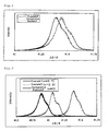
- FIG. 1 A measurement result of the XRD pattern of the carrier core material for electrophotographic developer according to the example 1 and the comparative example 1 is shown in FIG. 1 , for the purpose of examination. The measurement was performed when (2 ⁇ / ⁇ ) is a value between 41.00° and 41.75° where the peak having a maximum intensity appears.
- the peak of the comparative example 1 is broad in such a manner as being spread in the form of a skirt toward a higher angle side, compared with the peak of the example 1.
- the XRD pattern shows that there is a small existence ratio of the low magnetic susceptibility particles in the magnetic powders according to the example 1.
- the magnetic powders of the comparative example 1 contain particles with deviated composition, namely, contains a plurality of low magnetic susceptibility particles.
- Measurement results of the half-value widths in the XRD pattern of the carrier core material for electrophotographic developer according to the example 1 and the comparative example 1 indicate 0.137 and 0.195, respectively (these values are described in table 1)
- the same mixing ratio of the raw materials and sintering conditions are the same.
- the raw material particle size is different between the example 1 and the comparative example 1.
- value D90 of the particle size distribution of the example 1 is 1.0 ⁇ m or less, and it is found that the example 1 is manufactured under a condition that there are no rough raw material particles. From the data of the example 1 and the comparative example 1, it is found that the half-value width of the XRD peak having the maximum intensity is narrower, as the value D90 of the raw materials is smaller.
- the half-value width becomes narrower, and this is because as a result of uniformly mixing the raw material powders by using fine raw materials, the existence ratio of the particles that deviate in composition is lowered. Accordingly, it can be considered that the ratio of the low magnetic susceptibility particles generated due to deviation in composition is also lowered.
- the carrier scattering amount of the comparative example 1 is extremely increased, such as about five times the carrier of the example 1, corresponding to a level that causes a serious problem in the electrophotographic development. Accordingly, it is found that in order to suppress the carrier scattering for performing excellent electrophotographic development, it is necessary to use the carrier core material, with the half-value width of the XRD peak having the maximum intensity set to be 0.190 or less or preferably set to be 0.180 or less.
- examples 1 and 2 and the comparative example 2 in which the value of x is changed in the composition formula Mg x Mn (1-x) Fe y O 4 will be described. From FIG. 2 , it is found that the value of x is increased, and as the composition ratio of Mg is increased, the position of the XRD peak is shifted toward the higher angle side. This is because ion radius of Mg is smaller than Mn ion radius.
- These low magnetic susceptibility particles are generated as a result of causing oxidation of the carrier particles by oxygen that slightly exists in the furnace in the step of sintering. Meanwhile, it can be considered that the carrier particles of the example 1 and the example 2 having Mg in the ferrite and satisfying 0 ⁇ x are prevented from being oxidized, and the low magnetic susceptibility particles are reduced. Values of the half-value widths of the carrier powders according to the examples 1 and 2, and comparative example 2 were respectively 0.137, 0.145, and 0.182 (these values are described in table 1).
- the XRD pattern of the carrier particles according to examples 3 to 5 sintered in the atmospheric air is shown in FIG. 3 .
- the position of the peak is slightly changed by the change of the values of x, y in the composition formula Mg x Mn (1-x) Fe y O 4 .
- values of the half-value widths were not changed so much, and the values were respectively 0.157 (example 3), 0.160 (example 4), and 0.167 (example 5). Therefore, it was confirmed that the carrier powders have narrow half-value widths of the XRD pattern, even if sintering was performed in an atmosphere of higher oxygen partial pressure, than that of the examples 1, 2 and the comparative example 1.
- the magnetic susceptibility ( ⁇ 1000 ) was 15 A.m 2 /kg (15 emu/g) or more and 65 A.m 2 /kg (65 emu/g) or less. Accordingly, it was found that there were less particles of high magnetic susceptibility for excessively hardening the magnetic brush, in addition to the fact that there were less amount of the low magnetic susceptibility particles. Meanwhile, in a case of the carrier particles according to the comparative example 2 not containing Mg, the magnetic susceptibility ( ⁇ 1000 ) was 71 A.m 2 /kg (71 emu/g) and it was found that this was a level for excessively hardening the magnetic brush.
- the carrier scattering amount was about 1.5 times that of the example 1, corresponding to a level not problematic in practical use. This is because by adding Mg as described above, particles with extremely low magnetic susceptibility are reduced.
- the carrier with less low magnetic susceptibility particles and suppressed carrier scattering, could be manufactured.
- the particle size distribution of the raw materials and the carrier core material was measured by using Microtrac (produced by Nikkiso, Model:9320-X100). From the obtained particle size distribution, 50 vol.%-cumulative particle size D50 and 90 vol.%-cumulative particle size D90 were calculated. Note that in the present invention, the value of this D50 was described as the average particle size of powders.
- the magnetic susceptibility was measured by using VSM(produced by TOEI INDUSTRY Co., LTD.VSM-7), and magnetic susceptibility ⁇ 1000(emu/g) in external magnetic field 7.958x10 4 A/m (1000 Oe) was obtained.
- the powder XRD pattern of the carrier core material was measured by using an X-Ray Diffractometer (produced by Rigaku, RINT2000). Cobalt was used in an X-ray source, to thereby generate X-ray, with acceleration voltage set to be 40kV, and current set to be 30mA. A diverging slit opening angle was 1/2°, a scattering slit opening angle was 1/2°, and a light receiving slit width was 0.15mm. Measurement was performed by step scan, with measurement interval set to be 0.002°, count time set to be 5 seconds, and the number of integration set to be 3, to thereby perform accurate measurement of the half-value widths.
- the carrier for electrophotographic developer was generally used, with the carrier core material coated with resin.
- the shape of the XRD pattern and the half-value width of the peak are not changed, because the X-ray transmits through the resin.
- the carrier core material was filled into a magnetic drum having diameter 50mm and surface magnetic force 1000Gauss, then this magnetic drum was rotated at 270rpm for 30 minutes, and thereafter scattered particles are recovered, and weights thereof were measured.
Landscapes
- Physics & Mathematics (AREA)
- General Physics & Mathematics (AREA)
- Chemical & Material Sciences (AREA)
- Chemical Kinetics & Catalysis (AREA)
- Spectroscopy & Molecular Physics (AREA)
- Engineering & Computer Science (AREA)
- Metallurgy (AREA)
- Developing Agents For Electrophotography (AREA)
Claims (7)
- Trägerkernmaterial für Elektrofotografie-Entwickler, ausgedrückt durch eine allgemeine Formel MgxMn(1-x)FeyO4, welche 0 < x < 1 und 1,6 ≤ y ≤ 2,4 erfüllt, wobei eine Halbwertsbreite B eines Peaks mit einer maximalen Intensität in einem Pulverröntgen-Beugungsmuster B ≤ 0,180 Grad erfüllt.
- Trägerkernmaterial für Elektrofotografie-Entwickler gemäß Anspruch 1, wobei eine allgemeine Formel durch MgxMn(1-x)FeyO4, welche 0 < x ≤ 0,8 und 1,6 ≤ y ≤ 2,4 erfüllt, ausgedrückt wird.
- Trägerkernmaterial für Elektrofotografie-Entwickler gemäß Anspruch 1 oder 2, wobei die magnetische Suszeptibilität σ1000 in einem externen Magnetfeld von 7,958x104 A/m (1000 Oe) 15 A·m2/kg (emu/g) ≤ σ1000 ≤ 65 A·m2/kg (emu/g) erfüllt.
- Trägerkernmaterial für Elektrofotografie-Entwickler gemäß einem der Ansprüche 1 bis 3, wobei eine mittlere Teilchengröße 10 µm oder mehr und 80 µm oder weniger ist.
- Verfahren zur Herstellung eines Trägerkernmaterials für Elektrofotografie-Entwickler, umfassend die Schritte:das Herstellen von Fe-Rohmaterialpulver, Mn-Rohmaterialpulver und Mg-Rohmaterialpulver, danach das Aufteilen des gesamten Volumens an Teilchen in die jeweilige Teilchengröße, und das Erhalten einer Sammelkurve eines Volumens in jeder Teilchengröße von der Seite einer Kleinteilchenseite, mit dem gesamten Volumen der Teilchen eingestellt als 100%, und das Feinermachen der Teilchen, so daß ein Wert von D90 auf 1,0 µm oder weniger eingestellt wird, wenn die Teilchengröße bei der Sammelkurve von 90% durch D90 ausgedrückt wird,das Überführen der erhaltenen feinen Teilchen in eine Aufschlämmung durch Rühren der Pulver in ein Lösungsmedium,das Erhalten von granulierten Pulvern durch Trocknen und Granulieren der erhaltenen Aufschlämmung,das Erhalten eines gesinterten Materials mit einer magnetischen Phase durch Sintern der erhaltenen granulierten Pulver, unddas Überführen des erhaltenen gesinterten Materials in Pulver durch Anwenden von Pulverisierungsverfahren darauf, um danach eine vorgeschriebene Teilchengrößenverteilung aufzuweisen.
- Träger für Elektrofotografie-Entwickler, worin das Trägerkernmaterial gemäß einem der Ansprüche 1 bis 4 mit Harz beschichtet ist.
- Elektrofotografie-Entwickler, welcher den Träger für Elektrofotografie-Entwickler gemäß Anspruch 6 und Toner einschließt.
Applications Claiming Priority (2)
| Application Number | Priority Date | Filing Date | Title |
|---|---|---|---|
| JP2007103290A JP5038002B2 (ja) | 2007-04-10 | 2007-04-10 | 電子写真現像剤用キャリア芯材およびその製造方法、電子写真現像剤用キャリア、並びに電子写真現像剤 |
| PCT/JP2008/057025 WO2008126869A1 (ja) | 2007-04-10 | 2008-04-09 | 電子写真現像剤用キャリア芯材およびその製造方法、電子写真現像剤用キャリア、並びに電子写真現像剤 |
Publications (3)
| Publication Number | Publication Date |
|---|---|
| EP2136253A1 EP2136253A1 (de) | 2009-12-23 |
| EP2136253A4 EP2136253A4 (de) | 2010-06-30 |
| EP2136253B1 true EP2136253B1 (de) | 2015-11-18 |
Family
ID=39863966
Family Applications (1)
| Application Number | Title | Priority Date | Filing Date |
|---|---|---|---|
| EP08740128.7A Active EP2136253B1 (de) | 2007-04-10 | 2008-04-09 | Trägerkernmaterial für ein elektrofotogrfisches entwicklungsmittel, verfahren zur herstellung des trägerkernmaterials, träger für ein elektrofotografisches entwicklungsmittel und elektrofotografisches entwicklungsmittel |
Country Status (6)
| Country | Link |
|---|---|
| US (1) | US8592123B2 (de) |
| EP (1) | EP2136253B1 (de) |
| JP (1) | JP5038002B2 (de) |
| KR (1) | KR101468247B1 (de) |
| CN (1) | CN101663622B (de) |
| WO (1) | WO2008126869A1 (de) |
Families Citing this family (7)
| Publication number | Priority date | Publication date | Assignee | Title |
|---|---|---|---|---|
| JP5298481B2 (ja) * | 2006-09-14 | 2013-09-25 | コニカミノルタ株式会社 | キャリアの製造方法 |
| JP2011107286A (ja) * | 2009-11-13 | 2011-06-02 | Dowa Electronics Materials Co Ltd | 電子写真現像用キャリア芯材およびその製造方法、電子写真現像用キャリア並びに二成分系電子写真現像剤 |
| JP5478322B2 (ja) * | 2010-03-30 | 2014-04-23 | Dowaエレクトロニクス株式会社 | フェライト粒子及びそれを用いた電子写真現像用キャリア、電子写真用現像剤並びにフェライト粒子の製造方法 |
| EP2555056B1 (de) * | 2010-03-31 | 2017-01-25 | DOWA Electronics Materials Co., Ltd. | Trägerkernmaterial für elektrofotografisches entwicklungsmittel, träger für elektrofotografisches entwicklungsmittel und elektrofotografisches entwicklungsmittel |
| JP5977924B2 (ja) * | 2011-03-16 | 2016-08-24 | Dowaエレクトロニクス株式会社 | 電子写真現像剤用キャリア芯材の製造方法、電子写真現像剤用キャリアの製造方法、および電子写真現像剤の製造方法 |
| JP6494453B2 (ja) * | 2015-07-10 | 2019-04-03 | Dowaエレクトロニクス株式会社 | キャリア芯材並びにこれを用いた電子写真現像用キャリア及び電子写真用現像剤 |
| US10409188B2 (en) * | 2017-02-10 | 2019-09-10 | Canon Kabushiki Kaisha | Magnetic carrier, two-component developer, replenishing developer, and image forming method |
Family Cites Families (11)
| Publication number | Priority date | Publication date | Assignee | Title |
|---|---|---|---|---|
| JP4734598B2 (ja) * | 1999-09-21 | 2011-07-27 | Dowaエレクトロニクス株式会社 | ソフトフェライトの製造法 |
| JP3828727B2 (ja) * | 2000-08-04 | 2006-10-04 | 三井金属鉱業株式会社 | 酸化鉄粒子 |
| JP2002296846A (ja) | 2001-03-30 | 2002-10-09 | Powdertech Co Ltd | 電子写真現像剤用キャリア及び該キャリアを用いた現像剤 |
| JP2006038961A (ja) * | 2004-07-22 | 2006-02-09 | Fuji Xerox Co Ltd | 静電荷像現像用キャリア、静電荷像現像剤、静電荷像現像用キャリアの製造方法および画像形成方法 |
| JP4578295B2 (ja) * | 2005-03-18 | 2010-11-10 | 京セラミタ株式会社 | 2成分現像剤用磁性トナーおよび該現像剤を用いた画像形成方法 |
| CN1851560A (zh) * | 2005-04-22 | 2006-10-25 | 株式会社理光 | 电子照相调色剂、显影剂以及图像形成装置 |
| JP2006323211A (ja) * | 2005-05-19 | 2006-11-30 | Dowa Mining Co Ltd | 電子写真現像用キャリアおよびその製造方法、並びに電子写真現像剤 |
| JP4781015B2 (ja) * | 2005-06-03 | 2011-09-28 | パウダーテック株式会社 | 電子写真用フェライトキャリア芯材、電子写真用フェライトキャリア及びこれらの製造方法、並びに該フェライトキャリアを用いた電子写真用現像剤 |
| JP4862181B2 (ja) * | 2005-06-22 | 2012-01-25 | Dowaエレクトロニクス株式会社 | 電子写真現像用キャリア芯材およびその製造方法、電子写真現像用キャリア、並びに電子写真現像剤 |
| JP2007034149A (ja) * | 2005-07-29 | 2007-02-08 | Fujifilm Holdings Corp | 回転検出方法及び装置、及び写真フイルムパトローネのフイルム係止検出方法及び装置 |
| EP2439594B1 (de) * | 2005-09-29 | 2013-07-24 | DOWA IP Creation Co., Ltd. | Trägerkernmaterial für elektrofotografischen Entwickler, Träger für elektrofotografischen Entwickler, Verfahren zu dessen Herstellung und elektrofotografischer Entwickler |
-
2007
- 2007-04-10 JP JP2007103290A patent/JP5038002B2/ja active Active
-
2008
- 2008-04-09 WO PCT/JP2008/057025 patent/WO2008126869A1/ja active Application Filing
- 2008-04-09 EP EP08740128.7A patent/EP2136253B1/de active Active
- 2008-04-09 US US12/450,321 patent/US8592123B2/en active Active
- 2008-04-09 KR KR1020097023383A patent/KR101468247B1/ko not_active IP Right Cessation
- 2008-04-09 CN CN200880011592XA patent/CN101663622B/zh not_active Expired - Fee Related
Also Published As
| Publication number | Publication date |
|---|---|
| CN101663622A (zh) | 2010-03-03 |
| EP2136253A1 (de) | 2009-12-23 |
| CN101663622B (zh) | 2013-03-20 |
| KR101468247B1 (ko) | 2014-12-03 |
| US20100075244A1 (en) | 2010-03-25 |
| JP5038002B2 (ja) | 2012-10-03 |
| JP2008261955A (ja) | 2008-10-30 |
| WO2008126869A1 (ja) | 2008-10-23 |
| US8592123B2 (en) | 2013-11-26 |
| EP2136253A4 (de) | 2010-06-30 |
| KR20090126325A (ko) | 2009-12-08 |
Similar Documents
| Publication | Publication Date | Title |
|---|---|---|
| EP2131248B1 (de) | Trägerkernmaterial für einen elektrofotografischen entwickler und verfahren zu seiner herstellung, träger für einen elektrofotografischen entwickler und elektrofotografischer entwickler | |
| EP2136253B1 (de) | Trägerkernmaterial für ein elektrofotogrfisches entwicklungsmittel, verfahren zur herstellung des trägerkernmaterials, träger für ein elektrofotografisches entwicklungsmittel und elektrofotografisches entwicklungsmittel | |
| EP2557457B1 (de) | Ferritträger-kernmaterial für elektrofotografische entwickler, ferritträger und herstellungsverfahren für beides sowie elektrofotografische entwickler mit dem ferritträger | |
| JP2008241742A5 (de) | ||
| EP2615499B1 (de) | Poröses Ferritkernmaterial für elektrofotografischen Entwickler, harzbeschichteter Ferrit-Träger und elektrofotografischer Entwickler, der den Ferrit-Träger verwendet | |
| EP3932870A1 (de) | Ferritteilchen, trägerkernmaterial für elektrofotografischen entwickler, träger für elektrofotografischen entwickler und elektrofotografischer entwickler | |
| JP2008261955A5 (de) | ||
| EP2980023A1 (de) | Ferritteilchen und träger für einen elektrofotografischen entwickler damit, elektrofotografischer entwickler und verfahren zur herstellung der ferritteilchen | |
| EP1840660A2 (de) | Ferromagnetisches Pulver, Träger für einen elektrofotografischen Entwickler, Herstellungsverfahren dafür und elektrofotografischer Entwickler | |
| JP2011170272A (ja) | 電子写真現像剤用キャリア芯材およびその製造方法 | |
| JP2009237155A (ja) | 電子写真現像剤用キャリア芯材およびその製造方法、電子写真現像剤用キャリア、並びに電子写真現像剤 | |
| EP4130884A1 (de) | Ferritteilchen, kernmaterial für elektrofotografischen entwicklerträger, elektrofotografischer entwicklerträger und elektrofotografischer entwickler | |
| EP2891925B1 (de) | Trägerkernmaterial für einen elektrofotografischen entwickler, träger für einen elektrofotografischen entwickler und elektrofotografischer entwickler | |
| JP5260118B2 (ja) | 電子写真現像剤用キャリア芯材およびその製造方法、電子写真現像剤用磁性キャリア並びに電子写真現像剤 | |
| JP2010002519A (ja) | 電子写真現像剤用キャリア芯材とその製造方法、電子写真現像剤用キャリア並びに電子写真現像剤 | |
| EP4130885A1 (de) | Ferritteilchen, kernmaterial für elektrofotografischen entwicklerträger, elektrofotografischer entwicklerträger und elektrofotografischer entwickler | |
| JP5748258B2 (ja) | 電子写真現像剤用キャリア芯材およびその製造方法 | |
| EP4349788A1 (de) | Ferritteilchen, träger für elektrofotografischen entwickler, elektrofotografischer entwickler und ferritteilchenherstellungsverfahren | |
| JP2011107286A (ja) | 電子写真現像用キャリア芯材およびその製造方法、電子写真現像用キャリア並びに二成分系電子写真現像剤 | |
| EP4349789A1 (de) | Ferritteilchen, träger für elektrofotografischen entwickler, elektrofotografischer entwickler und verfahren zur herstellung des ferritteilchens | |
| JP2009237049A (ja) | 電子写真現像剤用キャリア芯材およびその製造方法 | |
| WO2014050644A1 (ja) | 焼結粒子及びそれを用いた電子写真現像剤用キャリア、電子写真用現像剤並びに焼結粒子の製造方法 | |
| EP3492989A1 (de) | Ferritträgerkernmaterial für elektrofotografischen entwickler, träger für elektrofotografischen entwickler und elektrofotografischer entwickler |
Legal Events
| Date | Code | Title | Description |
|---|---|---|---|
| PUAI | Public reference made under article 153(3) epc to a published international application that has entered the european phase |
Free format text: ORIGINAL CODE: 0009012 |
|
| 17P | Request for examination filed |
Effective date: 20091015 |
|
| AK | Designated contracting states |
Kind code of ref document: A1 Designated state(s): AT BE BG CH CY CZ DE DK EE ES FI FR GB GR HR HU IE IS IT LI LT LU LV MC MT NL NO PL PT RO SE SI SK TR |
|
| A4 | Supplementary search report drawn up and despatched |
Effective date: 20100528 |
|
| DAX | Request for extension of the european patent (deleted) | ||
| 17Q | First examination report despatched |
Effective date: 20120917 |
|
| GRAP | Despatch of communication of intention to grant a patent |
Free format text: ORIGINAL CODE: EPIDOSNIGR1 |
|
| INTG | Intention to grant announced |
Effective date: 20150529 |
|
| GRAS | Grant fee paid |
Free format text: ORIGINAL CODE: EPIDOSNIGR3 |
|
| GRAP | Despatch of communication of intention to grant a patent |
Free format text: ORIGINAL CODE: EPIDOSNIGR1 |
|
| GRAA | (expected) grant |
Free format text: ORIGINAL CODE: 0009210 |
|
| INTG | Intention to grant announced |
Effective date: 20150929 |
|
| AK | Designated contracting states |
Kind code of ref document: B1 Designated state(s): AT BE BG CH CY CZ DE DK EE ES FI FR GB GR HR HU IE IS IT LI LT LU LV MC MT NL NO PL PT RO SE SI SK TR |
|
| REG | Reference to a national code |
Ref country code: GB Ref legal event code: FG4D |
|
| REG | Reference to a national code |
Ref country code: CH Ref legal event code: EP |
|
| REG | Reference to a national code |
Ref country code: AT Ref legal event code: REF Ref document number: 761844 Country of ref document: AT Kind code of ref document: T Effective date: 20151215 |
|
| REG | Reference to a national code |
Ref country code: IE Ref legal event code: FG4D |
|
| REG | Reference to a national code |
Ref country code: DE Ref legal event code: R096 Ref document number: 602008041256 Country of ref document: DE |
|
| REG | Reference to a national code |
Ref country code: NL Ref legal event code: FP |
|
| REG | Reference to a national code |
Ref country code: FR Ref legal event code: PLFP Year of fee payment: 9 |
|
| REG | Reference to a national code |
Ref country code: LT Ref legal event code: MG4D |
|
| REG | Reference to a national code |
Ref country code: AT Ref legal event code: MK05 Ref document number: 761844 Country of ref document: AT Kind code of ref document: T Effective date: 20151118 |
|
| PG25 | Lapsed in a contracting state [announced via postgrant information from national office to epo] |
Ref country code: HR Free format text: LAPSE BECAUSE OF FAILURE TO SUBMIT A TRANSLATION OF THE DESCRIPTION OR TO PAY THE FEE WITHIN THE PRESCRIBED TIME-LIMIT Effective date: 20151118 Ref country code: ES Free format text: LAPSE BECAUSE OF FAILURE TO SUBMIT A TRANSLATION OF THE DESCRIPTION OR TO PAY THE FEE WITHIN THE PRESCRIBED TIME-LIMIT Effective date: 20151118 Ref country code: IT Free format text: LAPSE BECAUSE OF FAILURE TO SUBMIT A TRANSLATION OF THE DESCRIPTION OR TO PAY THE FEE WITHIN THE PRESCRIBED TIME-LIMIT Effective date: 20151118 Ref country code: LT Free format text: LAPSE BECAUSE OF FAILURE TO SUBMIT A TRANSLATION OF THE DESCRIPTION OR TO PAY THE FEE WITHIN THE PRESCRIBED TIME-LIMIT Effective date: 20151118 Ref country code: IS Free format text: LAPSE BECAUSE OF FAILURE TO SUBMIT A TRANSLATION OF THE DESCRIPTION OR TO PAY THE FEE WITHIN THE PRESCRIBED TIME-LIMIT Effective date: 20160318 Ref country code: NO Free format text: LAPSE BECAUSE OF FAILURE TO SUBMIT A TRANSLATION OF THE DESCRIPTION OR TO PAY THE FEE WITHIN THE PRESCRIBED TIME-LIMIT Effective date: 20160218 |
|
| PG25 | Lapsed in a contracting state [announced via postgrant information from national office to epo] |
Ref country code: AT Free format text: LAPSE BECAUSE OF FAILURE TO SUBMIT A TRANSLATION OF THE DESCRIPTION OR TO PAY THE FEE WITHIN THE PRESCRIBED TIME-LIMIT Effective date: 20151118 Ref country code: LV Free format text: LAPSE BECAUSE OF FAILURE TO SUBMIT A TRANSLATION OF THE DESCRIPTION OR TO PAY THE FEE WITHIN THE PRESCRIBED TIME-LIMIT Effective date: 20151118 Ref country code: GR Free format text: LAPSE BECAUSE OF FAILURE TO SUBMIT A TRANSLATION OF THE DESCRIPTION OR TO PAY THE FEE WITHIN THE PRESCRIBED TIME-LIMIT Effective date: 20160219 Ref country code: PT Free format text: LAPSE BECAUSE OF FAILURE TO SUBMIT A TRANSLATION OF THE DESCRIPTION OR TO PAY THE FEE WITHIN THE PRESCRIBED TIME-LIMIT Effective date: 20160318 Ref country code: SE Free format text: LAPSE BECAUSE OF FAILURE TO SUBMIT A TRANSLATION OF THE DESCRIPTION OR TO PAY THE FEE WITHIN THE PRESCRIBED TIME-LIMIT Effective date: 20151118 Ref country code: PL Free format text: LAPSE BECAUSE OF FAILURE TO SUBMIT A TRANSLATION OF THE DESCRIPTION OR TO PAY THE FEE WITHIN THE PRESCRIBED TIME-LIMIT Effective date: 20151118 Ref country code: FI Free format text: LAPSE BECAUSE OF FAILURE TO SUBMIT A TRANSLATION OF THE DESCRIPTION OR TO PAY THE FEE WITHIN THE PRESCRIBED TIME-LIMIT Effective date: 20151118 |
|
| PG25 | Lapsed in a contracting state [announced via postgrant information from national office to epo] |
Ref country code: CZ Free format text: LAPSE BECAUSE OF FAILURE TO SUBMIT A TRANSLATION OF THE DESCRIPTION OR TO PAY THE FEE WITHIN THE PRESCRIBED TIME-LIMIT Effective date: 20151118 |
|
| REG | Reference to a national code |
Ref country code: DE Ref legal event code: R097 Ref document number: 602008041256 Country of ref document: DE |
|
| PG25 | Lapsed in a contracting state [announced via postgrant information from national office to epo] |
Ref country code: RO Free format text: LAPSE BECAUSE OF FAILURE TO SUBMIT A TRANSLATION OF THE DESCRIPTION OR TO PAY THE FEE WITHIN THE PRESCRIBED TIME-LIMIT Effective date: 20151118 Ref country code: DK Free format text: LAPSE BECAUSE OF FAILURE TO SUBMIT A TRANSLATION OF THE DESCRIPTION OR TO PAY THE FEE WITHIN THE PRESCRIBED TIME-LIMIT Effective date: 20151118 Ref country code: SK Free format text: LAPSE BECAUSE OF FAILURE TO SUBMIT A TRANSLATION OF THE DESCRIPTION OR TO PAY THE FEE WITHIN THE PRESCRIBED TIME-LIMIT Effective date: 20151118 Ref country code: EE Free format text: LAPSE BECAUSE OF FAILURE TO SUBMIT A TRANSLATION OF THE DESCRIPTION OR TO PAY THE FEE WITHIN THE PRESCRIBED TIME-LIMIT Effective date: 20151118 Ref country code: BE Free format text: LAPSE BECAUSE OF NON-PAYMENT OF DUE FEES Effective date: 20160430 |
|
| PLBE | No opposition filed within time limit |
Free format text: ORIGINAL CODE: 0009261 |
|
| STAA | Information on the status of an ep patent application or granted ep patent |
Free format text: STATUS: NO OPPOSITION FILED WITHIN TIME LIMIT |
|
| 26N | No opposition filed |
Effective date: 20160819 |
|
| PG25 | Lapsed in a contracting state [announced via postgrant information from national office to epo] |
Ref country code: SI Free format text: LAPSE BECAUSE OF FAILURE TO SUBMIT A TRANSLATION OF THE DESCRIPTION OR TO PAY THE FEE WITHIN THE PRESCRIBED TIME-LIMIT Effective date: 20151118 |
|
| REG | Reference to a national code |
Ref country code: CH Ref legal event code: PL |
|
| PG25 | Lapsed in a contracting state [announced via postgrant information from national office to epo] |
Ref country code: BE Free format text: LAPSE BECAUSE OF FAILURE TO SUBMIT A TRANSLATION OF THE DESCRIPTION OR TO PAY THE FEE WITHIN THE PRESCRIBED TIME-LIMIT Effective date: 20151118 Ref country code: LU Free format text: LAPSE BECAUSE OF FAILURE TO SUBMIT A TRANSLATION OF THE DESCRIPTION OR TO PAY THE FEE WITHIN THE PRESCRIBED TIME-LIMIT Effective date: 20160409 |
|
| REG | Reference to a national code |
Ref country code: IE Ref legal event code: MM4A |
|
| PG25 | Lapsed in a contracting state [announced via postgrant information from national office to epo] |
Ref country code: LI Free format text: LAPSE BECAUSE OF NON-PAYMENT OF DUE FEES Effective date: 20160430 Ref country code: CH Free format text: LAPSE BECAUSE OF NON-PAYMENT OF DUE FEES Effective date: 20160430 |
|
| REG | Reference to a national code |
Ref country code: FR Ref legal event code: PLFP Year of fee payment: 10 |
|
| PGFP | Annual fee paid to national office [announced via postgrant information from national office to epo] |
Ref country code: NL Payment date: 20170320 Year of fee payment: 10 |
|
| PG25 | Lapsed in a contracting state [announced via postgrant information from national office to epo] |
Ref country code: IE Free format text: LAPSE BECAUSE OF NON-PAYMENT OF DUE FEES Effective date: 20160409 |
|
| PGFP | Annual fee paid to national office [announced via postgrant information from national office to epo] |
Ref country code: GB Payment date: 20170405 Year of fee payment: 10 |
|
| REG | Reference to a national code |
Ref country code: FR Ref legal event code: PLFP Year of fee payment: 11 |
|
| PG25 | Lapsed in a contracting state [announced via postgrant information from national office to epo] |
Ref country code: HU Free format text: LAPSE BECAUSE OF FAILURE TO SUBMIT A TRANSLATION OF THE DESCRIPTION OR TO PAY THE FEE WITHIN THE PRESCRIBED TIME-LIMIT; INVALID AB INITIO Effective date: 20080409 Ref country code: CY Free format text: LAPSE BECAUSE OF FAILURE TO SUBMIT A TRANSLATION OF THE DESCRIPTION OR TO PAY THE FEE WITHIN THE PRESCRIBED TIME-LIMIT Effective date: 20151118 |
|
| PG25 | Lapsed in a contracting state [announced via postgrant information from national office to epo] |
Ref country code: TR Free format text: LAPSE BECAUSE OF FAILURE TO SUBMIT A TRANSLATION OF THE DESCRIPTION OR TO PAY THE FEE WITHIN THE PRESCRIBED TIME-LIMIT Effective date: 20151118 Ref country code: MC Free format text: LAPSE BECAUSE OF FAILURE TO SUBMIT A TRANSLATION OF THE DESCRIPTION OR TO PAY THE FEE WITHIN THE PRESCRIBED TIME-LIMIT Effective date: 20151118 Ref country code: MT Free format text: LAPSE BECAUSE OF NON-PAYMENT OF DUE FEES Effective date: 20160430 |
|
| PG25 | Lapsed in a contracting state [announced via postgrant information from national office to epo] |
Ref country code: BG Free format text: LAPSE BECAUSE OF FAILURE TO SUBMIT A TRANSLATION OF THE DESCRIPTION OR TO PAY THE FEE WITHIN THE PRESCRIBED TIME-LIMIT Effective date: 20151118 |
|
| REG | Reference to a national code |
Ref country code: NL Ref legal event code: MM Effective date: 20180501 |
|
| GBPC | Gb: european patent ceased through non-payment of renewal fee |
Effective date: 20180409 |
|
| PG25 | Lapsed in a contracting state [announced via postgrant information from national office to epo] |
Ref country code: NL Free format text: LAPSE BECAUSE OF NON-PAYMENT OF DUE FEES Effective date: 20180501 |
|
| PG25 | Lapsed in a contracting state [announced via postgrant information from national office to epo] |
Ref country code: GB Free format text: LAPSE BECAUSE OF NON-PAYMENT OF DUE FEES Effective date: 20180409 |
|
| PGFP | Annual fee paid to national office [announced via postgrant information from national office to epo] |
Ref country code: FR Payment date: 20240308 Year of fee payment: 17 |
|
| PGFP | Annual fee paid to national office [announced via postgrant information from national office to epo] |
Ref country code: DE Payment date: 20240227 Year of fee payment: 17 |