EP2136235A2 - Optisches Lichtquellensystem - Google Patents
Optisches Lichtquellensystem Download PDFInfo
- Publication number
- EP2136235A2 EP2136235A2 EP09007896A EP09007896A EP2136235A2 EP 2136235 A2 EP2136235 A2 EP 2136235A2 EP 09007896 A EP09007896 A EP 09007896A EP 09007896 A EP09007896 A EP 09007896A EP 2136235 A2 EP2136235 A2 EP 2136235A2
- Authority
- EP
- European Patent Office
- Prior art keywords
- optical system
- light source
- light
- lens group
- magnification conversion
- Prior art date
- Legal status (The legal status is an assumption and is not a legal conclusion. Google has not performed a legal analysis and makes no representation as to the accuracy of the status listed.)
- Granted
Links
Images




Classifications
-
- G—PHYSICS
- G02—OPTICS
- G02B—OPTICAL ELEMENTS, SYSTEMS OR APPARATUS
- G02B23/00—Telescopes, e.g. binoculars; Periscopes; Instruments for viewing the inside of hollow bodies; Viewfinders; Optical aiming or sighting devices
- G02B23/24—Instruments or systems for viewing the inside of hollow bodies, e.g. fibrescopes
- G02B23/2407—Optical details
- G02B23/2461—Illumination
Definitions
- the present invention relates generally to a light source optical system, and more particularly to a light guide illumination apparatus for endoscopes.
- the color imaging mode for electronic scopes generally includes the "mosaic filter mode” and the "field sequential illumination mode".
- the mosaic filter mode a solid-state image pickup device with a color filter formed per pixel is used on an imaging plane to obtain color images by white illumination.
- the field sequential mode on the other hand, a black-and-white solid-state image pickup device is used, and color filters for R, G, B, etc. are mounted in a light source apparatus that is an illumination means to time-divide illumination light thereby obtaining color images.
- the former allocates colors to the limited number of pixels; so it is lower in resolving power than the latter using a monochromatic solid-state image pickup device, and renders it difficult to control color reproduction because the color filters are on the imaging plane of the image pickup device.
- the latter enables color reproduction to be controlled by altering the characteristics of the color filters mounted in the light source apparatus, and makes better color reproduction possible.
- the interference type For the color filters located in the light source apparatus operating in the field sequential mode, the interference type is generally used. With this interference type filters, there is a change in the transmittance (reflectance) characteristics depending on the angle of incidence of light rays. For instance, when it comes to a filter designed such that the desired characteristics are obtained at the angle of incidence of 0° , the larger the angle of incidence, the more the transmitted wavelength shifts or ripples to a short wavelength side and the more of deviation there is from the desired characteristics with the result that color reproduction goes worse. To obtain the desired characteristics with the interference type filters yet with high precision, it is necessary to keep the angle of incidence from growing wide: this requirement is an imperative challenge to designing light source optical systems.
- a typical light source optical system of the field sequential illumination mode with color filters located in it is set forth in Patent Publication 1.
- this light source optical system as shown in Fig. 8 , light emanating from a light source 1 is somewhat moderately collected by a front unit 2a of a collective lens system 2, entering a filter 5. The light is then collected by a rear unit 2b of the collective lens system 2, entering the entrance end surface of a light guide 6.
- Such arrangement has some defects: it renders it difficult to diminish the diameter of light beams on the color filter surface, resulting in a bulky filter size and thus an increase in the size of the light source optical system.
- the angle of incidence of light onto the filters is wide with the result that color reproduction becomes inferior due to the above change in the angle-of-incidence characteristics.
- this optical system is built up of a collective optical system 2 for collecting parallel light beams emanating from a light source 1, a magnification conversion optical system 3 for reducing the diameter of light beams after passing through the collective optical system 2, and a positive lens group 4 that is located on an entrance end surface side of a light guide 6 with respect to the magnification conversion optical system 3 and collects light from the magnification conversion optical system 3 onto the entrance end surface of the light guide 6, with a color filter 5 interposed between the magnification conversion optical system 3 and the positive lens group 4.
- the parallel light beams from the light source 1 are subjected to magnification conversion into reduced, substantially parallel light beams. It is thus possible not only to diminish the diameter of light beams onto an interference coating surface thereby reducing apparatus size but also to keep the angle of incidence from growing wide thereby achieving satisfactory color reproduction.
- a color wheel 10 comprising R, G and B color filters 11R, 11G and 11B and a light block plate 12 for controlling exposure and light blocking. With this color wheel it is possible to improve brightness more because the smaller the diameter of light beams at that wheel position, the higher the efficiency of light use becomes.
- color filters dedicated to each viewing method must be mounted in an associated light source optical system: as color filter space grows wider, it allows for more color filters well fit for many viewing methods.
- the present invention has for its object to provide a light source optical system that is compatible with various viewing methods, prevents an associated light source apparatus from getting bulky, and makes sure brightness.
- a light source optical system comprising, in order from a light source, a collective optical system for collecting light from the light source, a magnification conversion optical system for reducing a pupil magnification, and a positive lens group for collecting light from said magnification conversion optical system, characterized by satisfying the following condition (1): d ⁇ f 2 ⁇ B + f 3 ⁇ F ⁇ d + f 3 ⁇ F where d is the principal point-to-point distance of said collective optical system and said magnification conversion optical system, f 2B is the rear focal length of said collective optical system, and f 3F is the front focal length of said magnification optical system.
- the light source optical system of the invention is further characterized by satisfying the following condition (2) with respect to the focal length of said positive lens group for collecting light from said magnification conversion optical system.
- condition (2) with respect to the focal length of said positive lens group for collecting light from said magnification conversion optical system.
- f 4 is the focal length of said positive lens group
- h 4 is the height of light rays at a chief plane of said positive lens group
- x is the principal point-to-point distance of said magnification conversion optical system and said positive lens group.
- the light source optical system of the invention is further characterized in that said positive lens group for collecting light from said magnification conversion optical system comprises at least two lenses, and satisfies the following condition (3): n 4 ⁇ b ⁇ n 4 ⁇ i where n 4b is the refractive index of a lens located in said positive lens group and on a light source side, and n 4i is the refractive index of a lens located in said positive lens group and on an exit side.
- the invention also provides a light source optical system comprising, in order from a light source side, a collective optical system for collecting light from the light source, a magnification conversion optical system for reducing a pupil magnification, and a positive lens group for collecting light from said magnification conversion optical system, characterized in that an achromatic lens is located between said light source and said collective optical system.
- Fig. 1 is illustrative of the basic arrangement of the inventive light source optical system for endoscopes.
- reference numeral 1 is a light source comprising a reflector 1a and a light source lamp 1b located substantially at the focal position of the reflector;
- 2 is a collective lens system (collective optical system) for collecting light emanating from the light source 1;
- 3 is a magnification conversion optical system for reducing the diameter of a light beam after passing through the collective lens system 2;
- 4 is a positive lens group that is located on an object side with respect to the magnification conversion optical system 3 for collecting and guiding light from the magnification conversion optical system 3 to a light guide 6;
- 5 is a color wheel that is located between the magnification conversion optical system 3 and the positive lens group 4, and comprises a plurality of color filters.
- the inventive light source optical system for endoscopes should be configured in such a way as to satisfy the following condition (1). d ⁇ f 2 ⁇ B + f 3 ⁇ F ⁇ d + f 3 ⁇ F
- the principal point-to-point distance d of the collective lens system 2 and the magnification conversion optical system 3 is less than the sum of the rear focal length f 2B of the collective lens system 2 and the front focal length f 3F of the magnification conversion optical system 3, i.e., when the left side of Condition (1) is satisfied, it is then possible to locate the color filters 5 at a position where the diameter of a light beam is smaller than that of a parallel light beam between the magnification conversion optical system 3 and the positive lens group 4 in such an optical system as to satisfy the lower limit to Condition (1) as indicated by a solid line in Fig. 2 . It is thus possible to reduce the size of the color filters 5 and color wheel.
- the sum of the focal lengths of the collective lens system 2 and magnification conversion optical system 3 exceeds the upper limit to Condition (1) (that is, the position where the rear focal length position of the collective lens system 2 is coincidence with the front principal point position of the magnification conversion optical system 3), the light converged by the collective lens system 2 will spread out after passing through the magnification conversion optical system 3. Then, the angle of incidence of light rays onto the color filters 5 will grow wide, giving rise to deterioration in color reproduction. For this reason, the sum of the focal lengths of the collective lens system (collective optical system) 2 and magnification conversion optical system 3 must be less than the upper limit to Condition (1).
- the color wheel is located at a position near to the magnification conversion optical system 3. It is then preferable that a light block plate is located more on the light source side than the color filters 5, because exposure and light blocking are implemented with a more reduced light beam diameter so that the efficiency of light use can be much more improved.
- the range of the focal length of the positive lens group 4 for allowing light rays passing through the magnification conversion optical system 4 to be efficiently incident onto the light guide 6 is determined by the following condition (2).
- Condition (2) is provided to limit the focal length of the positive lens group 4 so that in the optical system that satisfies Condition (1), the range of the angle of incidence of light rays onto the light guide 6 is determined.
- the focal length f 4 of the positive lens group 4 must satisfy: tanu / h 4 ⁇ 1 / f 4 ⁇ tanu / h 4 + 1 / x
- the NA of the light guide 6 should preferably be in the range of 0.5 to 0.9.
- Condition (2) 0.5 / h 4 ⁇ 1 / f 4 ⁇ 1 / x + 2 / h 4 light rays passing through the optical system here could be efficiently incident onto the light guide 6.
- the height of light rays incident onto the light source-side lens 4a in the positive lens group 4 is greater than that at the exit-side lens 4b.
- the radius of curvature of that lens 4a must be small to gather light to the end surface of the light guide 6.
- light rays incident onto the light source-side lens 4a are high, and to prevent that lens 4a from breaking off at the edge, it must have a greater thickness. This is not preferable in view of not only optical performance considerations such as total reflection but cost as well.
- the lens 4a located in the positive lens group 4 and more on the light source side is formed of a vitreous material having a refractive index higher than that of the exit-side lens 4b. That is, it is desired to satisfy Condition (3): n 4 ⁇ b ⁇ n 4 ⁇ i
- Such a light source optical system as depicted in Fig. 4 comprises a plurality of lenses, each having large positive power, and so has an extremely strong convex power as a whole, causing chromatic aberrations to occur more.
- an achromatic lens 2a is interposed between the light source 1 and the collective lens 2b in the collective optical system 2 so that there is stabilized image quality achievable with reduced or minimized chromatic aberrations.
- Such a light source optical system is small in terms of the angle of light emanating from the light source 1 and large in terms of the NA of light incident onto the light guide 6, and so it is preferable that a vitreous material having a combination of high refractive index and high dispersion, and a combination of low refractive index and low dispersion to hold back spherical aberrations is used for the achromatic lens 2a.
- the size of the collective lens 2a can then be reduced by lowering the height of on-axis light rays after passing through the achromatic lens 2a.
- the achromatic lens 2a is located with its convex surface lying on the exit side, on the other hand, on-axis and off-axis light rays after passing through the achromatic lens can be well separated at the lens surface of the collective lens 2b in terms of height. Accordingly, when an aspheric lens is used for the collective lens 2b, there is a merit obtained that correction of aberrations is facilitated by aspheric design. Taking advantage of such features, it is preferable to determine the orientation of the convex surface of the achromatic lens depending on what purpose and specifications the light source is used for and in.
- f c is the composite focal length of the achromatic lens
- f 2 is the focal length of the collective optical system
- a reflection type infrared cut filter 7 located between the light source 1 and the collective optical system 2 satisfies the following condition, and an absorption type infrared filter 8 is located with the filter surface lying in the direction vertical to an optical axis.
- ⁇ is the angle of the reflection type infrared cut filter 7 with the direction vertical to the optical axis
- D is the pupil diameter of the light source lamp that forms the light source
- L is the distance from the pupil position of the light source lamp up to the surface of the reflection type infrared cut filter 7.
- the reflection type infrared cut filter 7 is located in such a way as to satisfy Condition (4), light rays do hardly enter the light source 1 even when parallel light emanating from the light source 1 is reflected at the surface of the infrared cut filter 7, resulting in prevention of deterioration of the light source.
- the absorption type infrared cut filter 8 is mounted in a predivided form so as to keep it from breaking due to the absorption of infrared radiation. Note here that the absorption type infrared cut filter 8 is all sand polished on the sides, and as light strikes there, there is scattering. If that filter is on the tilt, light strikes upon the sides of the cracks; in other words, that filter should be located vertically to the optical axis.
- the reflection or absorption type infrared cut filter is used in such arrangement, it can then be used safely without incurring inconveniences due to heat even in an endoscope light source where large quantities of light are projected.
- a light source optical system for endoscopes provided that is compatible with various viewing methods, prevents an associated light source apparatus from getting bulky, makes sure brightness, and is less susceptible to color changes.
- surface Nos. 0, 1, 2, 3, ... are indicated by r 0 , r 1 , r 2 , r 3 , ...
- surface No. 0 is the light source
- the effective diameter of the light source is indicated by the entrance pupil diameter of the light source.
- Aspheric surface shape is given by the following formula, provided that the Z-axis is defined by an optical axis direction, and the Y-axis is defined by the direction vertical to the optical axis.
- Z CY 2 / 1 + 1 - 1 + K ⁇ C 2 ⁇ Y 2 + A 4 ⁇ Y 4 + A 6 ⁇ Y 6 + A 8 ⁇ Y 8 + A 10 ⁇ Y 10 + A 12 ⁇ Y 12 +
- K is a conic coefficient
- a 4 , A 6 , A 8 , A 10 and A 12 are the fourth-, sixth-, eighth-, tenth- and twelfth-order aspheric coefficients.
- Example 1 light emanating from a light source 1 comprising a reflector 1a formed of paraboloid and a light source lamp 1b located substantially at the focal position thereof is collected by a collective optical system 2 comprising an achromatic lens 2a and a collective lens 2b, after which the light passes through a magnification conversion optical system 3 where a pupil is reduced, and then through a rotary filter 5.
- the light from the magnification conversion optical system 3 is collected through a positive lens group 4 onto a light guide 6 (the 19 th surface).
- a reflection type infrared cut filter 7 and an absorption type infrared cut filter 8 are interposed between the light source 1 and the collective optical system 2. More specifically, the reflection type infrared cut filter 7 is tilted from the direction vertical to the optical axis, and the absorption type infrared cut filter 8 is located in the direction vertical to the optical axis.
- the magnification conversion optical system 3 is made up of one aspheric lens having positive power, and the positive lens group 4 after the rotary filter 5 is made up of a spherical lens 4a and an aspheric lens 4b.
- the collective optical system 2 is made up of an achromatic lens 2a with the convex surface lying on the light source 1 side and an aspheric lens 2b.
- the size of the aspheric lens 2b can be diminished.
- the collective optical system 2 is made up of an achromatic lens 2a with the convex surface lying on the light guide 6 side and an aspheric lens 2b.
- On-axis and off-axis light rays after passing through the achromatic lens 2a are well separated in height on the lens surface of the aspheric lens 2b, offering a merit that correction of aberrations is facilitated by aspheric design.
- the first and second surfaces in the data described later are the reflection type infrared cut filter 7 that is located at a tilt of 15° from the direction vertical to the optical axis, and the third and fourth surfaces are the absorption type infrared cut filter 8 that is located vertically to the optical axis.
- the exit side surface (the ninth surface) of the collective lens 2b, the exit side surface (the twelfth surface) of the aspheric lens that is the magnification conversion optical system 3, and the entrance side surface (the seventeenth surface) of the aspheric lens 4b in the positive lens group 4 is made up of an aspheric surface represented by the aforesaid formula (a).
- Example 3 that is a modification to Example 1, there are the lens data of the optical system given, wherein chromatic aberrations on the surface of the blade stop are held back.
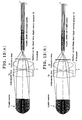
- Figs. 11(A) and 11(B) Light quantity control (light control) by the blade stop is shown in Figs. 11(A) and 11(B) , and shown in Fig. 12 is a graph of one exemplary relationship between stop-down quantity and color temperature when the blade stop 13 shown in Fig. 11 is opened or closed. If there is a color distribution on a light beam on the blade stop surface ( Fig. 11(A) shows that there is a coloring around the light beam due to the chromatic aberrations of the optical system, and Fig. 11(B) shows that with the blade stop reduced, that coloring prevails), there is then a color temperature change depending on the stop-down quantity. Accordingly, the quantity of color separation of light lays on the surface of the blade stop 13, for instance, should preferably be reduced in consideration of the light beam diameter and the shape of the blade stop 13.
- Fig. 13 is illustrative in conception of correction of chromatic aberrations on the blade stop surface. More specifically, Fig. 13(A) is illustrative in conception of an optical path taken per color, and Fig. 13(B) is illustrative of how chromatic aberrations on the light guide surface are held back. For the sake of simplification, the collective lens 2b is shown in the form of one lens. Note here that a light guidance rod 9 is located at the entrance end of the light guide 6.
- a complement to the above angle dependence of spectral transmittance of optical fibers and the color distribution of light beams on the blade stop surface may be necessary because they are not shown in the drawings.
- the spectral transmittance of optical fibers is such that as the angle of incident light grows large, it causes the red component to decrease (the blue component to increase relatively).
- the angle distribution of incident light onto optical fibers grows predominantly wide or the blue component increases.
- the color distribution in an area - where light is not shaded when there is a large stop-down quantity (there is a large quantity of shading) - turns red, it is then possible to hold back the color change of illumination light guided through the optical fibers.
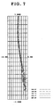
- Fig. 7 is a coma diagram for the optical system of Example 1, when light emanating from the light source 1 makes an angle of 4° with the optical axis, with the numerical aperture of light rays passing on the entrance pupil as ordinate and the amount of aberrations (mm) as abscissa.
- the optical system is designed such that coma has a somewhat positive value without being completely corrected, i.e., light rays gaining height on the entrance pupil are not collected on an optical system side with respect to the collection position of paraxial light rays, then off-axis light rays can efficiently be incident onto the end surface of the light guide 6 because they do not exceed the NA of the light guide.
- the aspheric lens is designed such that the curvature becomes weak in the effective diameter with a distance from the center of the lens.
- Examples 1 and 2 satisfy Conditions (1), (2) and (3) according to the invention.
- Example 1 Example 2 (1) d 36.279 34.266 f 2B +f 3F 37.436 35.576 d+f 3F 46.151 44.138 (2) 0.5/h 4 0.104 0.104 1/f 4 0.136 0.134 1/x+2/h 4 0.464 0.462 (3) n 4b 1.697 1.697 n 41 1.518 1.518
- Examples 1 and 2 also satisfy Condition (4) according to the invention, as follows.
Landscapes
- Physics & Mathematics (AREA)
- Astronomy & Astrophysics (AREA)
- General Physics & Mathematics (AREA)
- Optics & Photonics (AREA)
- Lenses (AREA)
- Endoscopes (AREA)
- Instruments For Viewing The Inside Of Hollow Bodies (AREA)
- Microscoopes, Condenser (AREA)
Applications Claiming Priority (1)
| Application Number | Priority Date | Filing Date | Title |
|---|---|---|---|
| JP2008157596A JP2009300916A (ja) | 2008-06-17 | 2008-06-17 | 光源光学系 |
Publications (3)
| Publication Number | Publication Date |
|---|---|
| EP2136235A2 true EP2136235A2 (de) | 2009-12-23 |
| EP2136235A3 EP2136235A3 (de) | 2010-10-06 |
| EP2136235B1 EP2136235B1 (de) | 2018-05-23 |
Family
ID=41059860
Family Applications (1)
| Application Number | Title | Priority Date | Filing Date |
|---|---|---|---|
| EP09007896.5A Active EP2136235B1 (de) | 2008-06-17 | 2009-06-16 | Optisches Lichtquellensystem |
Country Status (3)
| Country | Link |
|---|---|
| US (1) | US8218233B2 (de) |
| EP (1) | EP2136235B1 (de) |
| JP (1) | JP2009300916A (de) |
Cited By (1)
| Publication number | Priority date | Publication date | Assignee | Title |
|---|---|---|---|---|
| EP2543921A4 (de) * | 2010-06-10 | 2014-04-02 | Olympus Medical Systems Corp | Lichtquellenvorrichtung |
Families Citing this family (2)
| Publication number | Priority date | Publication date | Assignee | Title |
|---|---|---|---|---|
| US10107483B2 (en) | 2015-12-04 | 2018-10-23 | Kerr Corporation | Headlight |
| JP7208253B2 (ja) * | 2018-09-28 | 2023-01-18 | i-PRO株式会社 | 内視鏡 |
Citations (1)
| Publication number | Priority date | Publication date | Assignee | Title |
|---|---|---|---|---|
| JPH07303604A (ja) | 1994-05-13 | 1995-11-21 | Olympus Optical Co Ltd | 内視鏡用光源光学系 |
Family Cites Families (9)
| Publication number | Priority date | Publication date | Assignee | Title |
|---|---|---|---|---|
| JPH0625827B2 (ja) * | 1985-08-19 | 1994-04-06 | オリンパス光学工業株式会社 | 内視鏡用光源光学系 |
| JP2826315B2 (ja) | 1987-12-01 | 1998-11-18 | オリンパス光学工業株式会社 | 内視鏡用光源光学系 |
| JPH03118509A (ja) * | 1989-10-02 | 1991-05-21 | Olympus Optical Co Ltd | 内視鏡用光源光学系 |
| US5823943A (en) * | 1994-08-02 | 1998-10-20 | Olympus Optical Co., Ltd | Light source device for endoscopes |
| US5680257A (en) * | 1995-07-31 | 1997-10-21 | Texas Instruments Incorporated | Light collection optics for spatial light modulator |
| JP4311826B2 (ja) | 1999-09-14 | 2009-08-12 | オリンパス株式会社 | ライトガイド照明装置 |
| JP2001166214A (ja) * | 1999-12-03 | 2001-06-22 | Olympus Optical Co Ltd | 光学装置 |
| WO2004079428A1 (ja) * | 2003-03-03 | 2004-09-16 | Nikon Corporation | 顕微鏡デジタル画像取得システム |
| JP2005342034A (ja) | 2004-05-31 | 2005-12-15 | Pentax Corp | 内視鏡用光源装置 |
-
2008
- 2008-06-17 JP JP2008157596A patent/JP2009300916A/ja active Pending
-
2009
- 2009-06-16 EP EP09007896.5A patent/EP2136235B1/de active Active
- 2009-06-16 US US12/485,887 patent/US8218233B2/en active Active
Patent Citations (1)
| Publication number | Priority date | Publication date | Assignee | Title |
|---|---|---|---|---|
| JPH07303604A (ja) | 1994-05-13 | 1995-11-21 | Olympus Optical Co Ltd | 内視鏡用光源光学系 |
Cited By (1)
| Publication number | Priority date | Publication date | Assignee | Title |
|---|---|---|---|---|
| EP2543921A4 (de) * | 2010-06-10 | 2014-04-02 | Olympus Medical Systems Corp | Lichtquellenvorrichtung |
Also Published As
| Publication number | Publication date |
|---|---|
| US8218233B2 (en) | 2012-07-10 |
| US20090310211A1 (en) | 2009-12-17 |
| EP2136235B1 (de) | 2018-05-23 |
| JP2009300916A (ja) | 2009-12-24 |
| EP2136235A3 (de) | 2010-10-06 |
Similar Documents
| Publication | Publication Date | Title |
|---|---|---|
| US5936773A (en) | Image-forming optical apparatus having a decentered optical surface | |
| US8203798B2 (en) | Objective optical system | |
| KR101302271B1 (ko) | 어안 렌즈 및 촬상 장치 | |
| JP4245800B2 (ja) | 内視鏡対物レンズ | |
| US8477417B2 (en) | Imaging optical system, microscope apparatus including the imaging optical system, and stereoscopic microscope apparatus | |
| US11054630B2 (en) | Camera lens system for an endoscope, method for producing a camera lens system and an endoscope | |
| US20150301317A1 (en) | Infrared camera apparatus | |
| JPH0910170A (ja) | 内視鏡対物光学系 | |
| JP7416466B2 (ja) | 顕微観察装置及び検出器 | |
| US12484763B2 (en) | Objective optical system, image pickup apparatus, and endoscope | |
| EP2136235B1 (de) | Optisches Lichtquellensystem | |
| JP4066079B2 (ja) | 対物レンズ及びそれを用いた光学装置 | |
| CN110262000A (zh) | 一种小型化长焦透雾镜头和光电设备 | |
| JP2582144B2 (ja) | 撮影レンズ | |
| CN114755812B (zh) | 投影镜头系统以及图像投影装置 | |
| JP4683212B2 (ja) | 魚眼レンズ及び撮像装置 | |
| JP3376089B2 (ja) | 内視鏡用光源光学系 | |
| JPH11326757A (ja) | 赤外線用対物光学系 | |
| JP3851417B2 (ja) | 内視鏡対物光学系 | |
| JP2000187155A (ja) | 内視鏡対物光学系 | |
| US10146038B2 (en) | Disk scanning apparatus and microscope apparatus | |
| JP2013174905A (ja) | 光源光学系 | |
| CN222672044U (zh) | 一种荧光摄像卡口及内窥镜系统 | |
| JP2003075720A (ja) | 撮像用結像レンズ | |
| JP2007225642A (ja) | 赤外線吸収ガラスを用いた撮像レンズ |
Legal Events
| Date | Code | Title | Description |
|---|---|---|---|
| PUAI | Public reference made under article 153(3) epc to a published international application that has entered the european phase |
Free format text: ORIGINAL CODE: 0009012 |
|
| AK | Designated contracting states |
Kind code of ref document: A2 Designated state(s): AT BE BG CH CY CZ DE DK EE ES FI FR GB GR HR HU IE IS IT LI LT LU LV MC MK MT NL NO PL PT RO SE SI SK TR |
|
| PUAL | Search report despatched |
Free format text: ORIGINAL CODE: 0009013 |
|
| AK | Designated contracting states |
Kind code of ref document: A3 Designated state(s): AT BE BG CH CY CZ DE DK EE ES FI FR GB GR HR HU IE IS IT LI LT LU LV MC MK MT NL NO PL PT RO SE SI SK TR |
|
| AX | Request for extension of the european patent |
Extension state: AL BA RS |
|
| 17P | Request for examination filed |
Effective date: 20101203 |
|
| 17Q | First examination report despatched |
Effective date: 20120308 |
|
| RAP1 | Party data changed (applicant data changed or rights of an application transferred) |
Owner name: OLYMPUS CORPORATION |
|
| RAP1 | Party data changed (applicant data changed or rights of an application transferred) |
Owner name: OLYMPUS CORPORATION |
|
| RAP1 | Party data changed (applicant data changed or rights of an application transferred) |
Owner name: OLYMPUS CORPORATION |
|
| RIN1 | Information on inventor provided before grant (corrected) |
Inventor name: UNO, KANAE Inventor name: HANANO, KAZUNARI |
|
| GRAP | Despatch of communication of intention to grant a patent |
Free format text: ORIGINAL CODE: EPIDOSNIGR1 |
|
| INTG | Intention to grant announced |
Effective date: 20171214 |
|
| RIN1 | Information on inventor provided before grant (corrected) |
Inventor name: HANANO, KAZUNARI Inventor name: UNO, KANAE |
|
| GRAS | Grant fee paid |
Free format text: ORIGINAL CODE: EPIDOSNIGR3 |
|
| GRAA | (expected) grant |
Free format text: ORIGINAL CODE: 0009210 |
|
| AK | Designated contracting states |
Kind code of ref document: B1 Designated state(s): AT BE BG CH CY CZ DE DK EE ES FI FR GB GR HR HU IE IS IT LI LT LU LV MC MK MT NL NO PL PT RO SE SI SK TR |
|
| REG | Reference to a national code |
Ref country code: GB Ref legal event code: FG4D |
|
| REG | Reference to a national code |
Ref country code: CH Ref legal event code: EP |
|
| REG | Reference to a national code |
Ref country code: IE Ref legal event code: FG4D |
|
| REG | Reference to a national code |
Ref country code: AT Ref legal event code: REF Ref document number: 1001971 Country of ref document: AT Kind code of ref document: T Effective date: 20180615 |
|
| REG | Reference to a national code |
Ref country code: DE Ref legal event code: R096 Ref document number: 602009052407 Country of ref document: DE |
|
| REG | Reference to a national code |
Ref country code: NL Ref legal event code: MP Effective date: 20180523 |
|
| REG | Reference to a national code |
Ref country code: LT Ref legal event code: MG4D |
|
| PG25 | Lapsed in a contracting state [announced via postgrant information from national office to epo] |
Ref country code: NO Free format text: LAPSE BECAUSE OF FAILURE TO SUBMIT A TRANSLATION OF THE DESCRIPTION OR TO PAY THE FEE WITHIN THE PRESCRIBED TIME-LIMIT Effective date: 20180823 Ref country code: SE Free format text: LAPSE BECAUSE OF FAILURE TO SUBMIT A TRANSLATION OF THE DESCRIPTION OR TO PAY THE FEE WITHIN THE PRESCRIBED TIME-LIMIT Effective date: 20180523 Ref country code: BG Free format text: LAPSE BECAUSE OF FAILURE TO SUBMIT A TRANSLATION OF THE DESCRIPTION OR TO PAY THE FEE WITHIN THE PRESCRIBED TIME-LIMIT Effective date: 20180823 Ref country code: FI Free format text: LAPSE BECAUSE OF FAILURE TO SUBMIT A TRANSLATION OF THE DESCRIPTION OR TO PAY THE FEE WITHIN THE PRESCRIBED TIME-LIMIT Effective date: 20180523 Ref country code: LT Free format text: LAPSE BECAUSE OF FAILURE TO SUBMIT A TRANSLATION OF THE DESCRIPTION OR TO PAY THE FEE WITHIN THE PRESCRIBED TIME-LIMIT Effective date: 20180523 Ref country code: ES Free format text: LAPSE BECAUSE OF FAILURE TO SUBMIT A TRANSLATION OF THE DESCRIPTION OR TO PAY THE FEE WITHIN THE PRESCRIBED TIME-LIMIT Effective date: 20180523 |
|
| PG25 | Lapsed in a contracting state [announced via postgrant information from national office to epo] |
Ref country code: LV Free format text: LAPSE BECAUSE OF FAILURE TO SUBMIT A TRANSLATION OF THE DESCRIPTION OR TO PAY THE FEE WITHIN THE PRESCRIBED TIME-LIMIT Effective date: 20180523 Ref country code: NL Free format text: LAPSE BECAUSE OF FAILURE TO SUBMIT A TRANSLATION OF THE DESCRIPTION OR TO PAY THE FEE WITHIN THE PRESCRIBED TIME-LIMIT Effective date: 20180523 Ref country code: HR Free format text: LAPSE BECAUSE OF FAILURE TO SUBMIT A TRANSLATION OF THE DESCRIPTION OR TO PAY THE FEE WITHIN THE PRESCRIBED TIME-LIMIT Effective date: 20180523 Ref country code: GR Free format text: LAPSE BECAUSE OF FAILURE TO SUBMIT A TRANSLATION OF THE DESCRIPTION OR TO PAY THE FEE WITHIN THE PRESCRIBED TIME-LIMIT Effective date: 20180824 |
|
| REG | Reference to a national code |
Ref country code: AT Ref legal event code: MK05 Ref document number: 1001971 Country of ref document: AT Kind code of ref document: T Effective date: 20180523 |
|
| PG25 | Lapsed in a contracting state [announced via postgrant information from national office to epo] |
Ref country code: AT Free format text: LAPSE BECAUSE OF FAILURE TO SUBMIT A TRANSLATION OF THE DESCRIPTION OR TO PAY THE FEE WITHIN THE PRESCRIBED TIME-LIMIT Effective date: 20180523 Ref country code: PL Free format text: LAPSE BECAUSE OF FAILURE TO SUBMIT A TRANSLATION OF THE DESCRIPTION OR TO PAY THE FEE WITHIN THE PRESCRIBED TIME-LIMIT Effective date: 20180523 Ref country code: DK Free format text: LAPSE BECAUSE OF FAILURE TO SUBMIT A TRANSLATION OF THE DESCRIPTION OR TO PAY THE FEE WITHIN THE PRESCRIBED TIME-LIMIT Effective date: 20180523 Ref country code: EE Free format text: LAPSE BECAUSE OF FAILURE TO SUBMIT A TRANSLATION OF THE DESCRIPTION OR TO PAY THE FEE WITHIN THE PRESCRIBED TIME-LIMIT Effective date: 20180523 Ref country code: RO Free format text: LAPSE BECAUSE OF FAILURE TO SUBMIT A TRANSLATION OF THE DESCRIPTION OR TO PAY THE FEE WITHIN THE PRESCRIBED TIME-LIMIT Effective date: 20180523 Ref country code: CZ Free format text: LAPSE BECAUSE OF FAILURE TO SUBMIT A TRANSLATION OF THE DESCRIPTION OR TO PAY THE FEE WITHIN THE PRESCRIBED TIME-LIMIT Effective date: 20180523 Ref country code: SK Free format text: LAPSE BECAUSE OF FAILURE TO SUBMIT A TRANSLATION OF THE DESCRIPTION OR TO PAY THE FEE WITHIN THE PRESCRIBED TIME-LIMIT Effective date: 20180523 |
|
| REG | Reference to a national code |
Ref country code: CH Ref legal event code: PL |
|
| REG | Reference to a national code |
Ref country code: DE Ref legal event code: R097 Ref document number: 602009052407 Country of ref document: DE |
|
| PG25 | Lapsed in a contracting state [announced via postgrant information from national office to epo] |
Ref country code: IT Free format text: LAPSE BECAUSE OF FAILURE TO SUBMIT A TRANSLATION OF THE DESCRIPTION OR TO PAY THE FEE WITHIN THE PRESCRIBED TIME-LIMIT Effective date: 20180523 |
|
| REG | Reference to a national code |
Ref country code: BE Ref legal event code: MM Effective date: 20180630 |
|
| REG | Reference to a national code |
Ref country code: IE Ref legal event code: MM4A |
|
| PG25 | Lapsed in a contracting state [announced via postgrant information from national office to epo] |
Ref country code: LU Free format text: LAPSE BECAUSE OF NON-PAYMENT OF DUE FEES Effective date: 20180616 Ref country code: MC Free format text: LAPSE BECAUSE OF FAILURE TO SUBMIT A TRANSLATION OF THE DESCRIPTION OR TO PAY THE FEE WITHIN THE PRESCRIBED TIME-LIMIT Effective date: 20180523 |
|
| PLBE | No opposition filed within time limit |
Free format text: ORIGINAL CODE: 0009261 |
|
| STAA | Information on the status of an ep patent application or granted ep patent |
Free format text: STATUS: NO OPPOSITION FILED WITHIN TIME LIMIT |
|
| GBPC | Gb: european patent ceased through non-payment of renewal fee |
Effective date: 20180823 |
|
| PG25 | Lapsed in a contracting state [announced via postgrant information from national office to epo] |
Ref country code: FR Free format text: LAPSE BECAUSE OF NON-PAYMENT OF DUE FEES Effective date: 20180723 Ref country code: IE Free format text: LAPSE BECAUSE OF NON-PAYMENT OF DUE FEES Effective date: 20180616 Ref country code: CH Free format text: LAPSE BECAUSE OF NON-PAYMENT OF DUE FEES Effective date: 20180630 Ref country code: LI Free format text: LAPSE BECAUSE OF NON-PAYMENT OF DUE FEES Effective date: 20180630 |
|
| 26N | No opposition filed |
Effective date: 20190226 |
|
| PG25 | Lapsed in a contracting state [announced via postgrant information from national office to epo] |
Ref country code: BE Free format text: LAPSE BECAUSE OF NON-PAYMENT OF DUE FEES Effective date: 20180630 Ref country code: SI Free format text: LAPSE BECAUSE OF FAILURE TO SUBMIT A TRANSLATION OF THE DESCRIPTION OR TO PAY THE FEE WITHIN THE PRESCRIBED TIME-LIMIT Effective date: 20180523 |
|
| PG25 | Lapsed in a contracting state [announced via postgrant information from national office to epo] |
Ref country code: GB Free format text: LAPSE BECAUSE OF NON-PAYMENT OF DUE FEES Effective date: 20180823 |
|
| PG25 | Lapsed in a contracting state [announced via postgrant information from national office to epo] |
Ref country code: MT Free format text: LAPSE BECAUSE OF NON-PAYMENT OF DUE FEES Effective date: 20180616 |
|
| PG25 | Lapsed in a contracting state [announced via postgrant information from national office to epo] |
Ref country code: TR Free format text: LAPSE BECAUSE OF FAILURE TO SUBMIT A TRANSLATION OF THE DESCRIPTION OR TO PAY THE FEE WITHIN THE PRESCRIBED TIME-LIMIT Effective date: 20180523 |
|
| PG25 | Lapsed in a contracting state [announced via postgrant information from national office to epo] |
Ref country code: HU Free format text: LAPSE BECAUSE OF FAILURE TO SUBMIT A TRANSLATION OF THE DESCRIPTION OR TO PAY THE FEE WITHIN THE PRESCRIBED TIME-LIMIT; INVALID AB INITIO Effective date: 20090616 Ref country code: PT Free format text: LAPSE BECAUSE OF FAILURE TO SUBMIT A TRANSLATION OF THE DESCRIPTION OR TO PAY THE FEE WITHIN THE PRESCRIBED TIME-LIMIT Effective date: 20180523 |
|
| PG25 | Lapsed in a contracting state [announced via postgrant information from national office to epo] |
Ref country code: CY Free format text: LAPSE BECAUSE OF FAILURE TO SUBMIT A TRANSLATION OF THE DESCRIPTION OR TO PAY THE FEE WITHIN THE PRESCRIBED TIME-LIMIT Effective date: 20180523 Ref country code: MK Free format text: LAPSE BECAUSE OF NON-PAYMENT OF DUE FEES Effective date: 20180523 |
|
| PG25 | Lapsed in a contracting state [announced via postgrant information from national office to epo] |
Ref country code: IS Free format text: LAPSE BECAUSE OF FAILURE TO SUBMIT A TRANSLATION OF THE DESCRIPTION OR TO PAY THE FEE WITHIN THE PRESCRIBED TIME-LIMIT Effective date: 20180923 |
|
| P01 | Opt-out of the competence of the unified patent court (upc) registered |
Effective date: 20230528 |
|
| PGFP | Annual fee paid to national office [announced via postgrant information from national office to epo] |
Ref country code: DE Payment date: 20250618 Year of fee payment: 17 |