EP2136142A1 - Verfahren zur herstellung von glühkerzen und glühkerze - Google Patents
Verfahren zur herstellung von glühkerzen und glühkerze Download PDFInfo
- Publication number
- EP2136142A1 EP2136142A1 EP07738328A EP07738328A EP2136142A1 EP 2136142 A1 EP2136142 A1 EP 2136142A1 EP 07738328 A EP07738328 A EP 07738328A EP 07738328 A EP07738328 A EP 07738328A EP 2136142 A1 EP2136142 A1 EP 2136142A1
- Authority
- EP
- European Patent Office
- Prior art keywords
- distal end
- heating coil
- glow plug
- center pole
- manufacturing
- Prior art date
- Legal status (The legal status is an assumption and is not a legal conclusion. Google has not performed a legal analysis and makes no representation as to the accuracy of the status listed.)
- Withdrawn
Links
Images


Classifications
-
- F—MECHANICAL ENGINEERING; LIGHTING; HEATING; WEAPONS; BLASTING
- F23—COMBUSTION APPARATUS; COMBUSTION PROCESSES
- F23Q—IGNITION; EXTINGUISHING-DEVICES
- F23Q7/00—Incandescent ignition; Igniters using electrically-produced heat, e.g. lighters for cigarettes; Electrically-heated glowing plugs
- F23Q7/001—Glowing plugs for internal-combustion engines
-
- F—MECHANICAL ENGINEERING; LIGHTING; HEATING; WEAPONS; BLASTING
- F02—COMBUSTION ENGINES; HOT-GAS OR COMBUSTION-PRODUCT ENGINE PLANTS
- F02D—CONTROLLING COMBUSTION ENGINES
- F02D41/00—Electrical control of supply of combustible mixture or its constituents
- F02D41/20—Output circuits, e.g. for controlling currents in command coils
- F02D2041/2086—Output circuits, e.g. for controlling currents in command coils with means for detecting circuit failures
- F02D2041/2093—Output circuits, e.g. for controlling currents in command coils with means for detecting circuit failures detecting short circuits
-
- F—MECHANICAL ENGINEERING; LIGHTING; HEATING; WEAPONS; BLASTING
- F02—COMBUSTION ENGINES; HOT-GAS OR COMBUSTION-PRODUCT ENGINE PLANTS
- F02P—IGNITION, OTHER THAN COMPRESSION IGNITION, FOR INTERNAL-COMBUSTION ENGINES; TESTING OF IGNITION TIMING IN COMPRESSION-IGNITION ENGINES
- F02P19/00—Incandescent ignition, e.g. during starting of internal combustion engines; Combination of incandescent and spark ignition
- F02P19/02—Incandescent ignition, e.g. during starting of internal combustion engines; Combination of incandescent and spark ignition electric, e.g. layout of circuits of apparatus having glowing plugs
-
- F—MECHANICAL ENGINEERING; LIGHTING; HEATING; WEAPONS; BLASTING
- F23—COMBUSTION APPARATUS; COMBUSTION PROCESSES
- F23Q—IGNITION; EXTINGUISHING-DEVICES
- F23Q7/00—Incandescent ignition; Igniters using electrically-produced heat, e.g. lighters for cigarettes; Electrically-heated glowing plugs
- F23Q7/001—Glowing plugs for internal-combustion engines
- F23Q2007/004—Manufacturing or assembling methods
-
- H—ELECTRICITY
- H05—ELECTRIC TECHNIQUES NOT OTHERWISE PROVIDED FOR
- H05B—ELECTRIC HEATING; ELECTRIC LIGHT SOURCES NOT OTHERWISE PROVIDED FOR; CIRCUIT ARRANGEMENTS FOR ELECTRIC LIGHT SOURCES, IN GENERAL
- H05B2203/00—Aspects relating to Ohmic resistive heating covered by group H05B3/00
- H05B2203/027—Heaters specially adapted for glow plug igniters
-
- Y—GENERAL TAGGING OF NEW TECHNOLOGICAL DEVELOPMENTS; GENERAL TAGGING OF CROSS-SECTIONAL TECHNOLOGIES SPANNING OVER SEVERAL SECTIONS OF THE IPC; TECHNICAL SUBJECTS COVERED BY FORMER USPC CROSS-REFERENCE ART COLLECTIONS [XRACs] AND DIGESTS
- Y10—TECHNICAL SUBJECTS COVERED BY FORMER USPC
- Y10T—TECHNICAL SUBJECTS COVERED BY FORMER US CLASSIFICATION
- Y10T29/00—Metal working
- Y10T29/49—Method of mechanical manufacture
- Y10T29/49002—Electrical device making
- Y10T29/49082—Resistor making
- Y10T29/49083—Heater type
Definitions
- the present invention relates to a method for manufacturing a glow plug and a glow plug manufactured by this manufacturing method.
- this glow plug 100 is comprised of a cylindrical metal shell 3 extending in the direction of an axis O; a heating tube 4 which has a cylindrical shape extending in the direction of the axis O, has its distal end 4a closed, and is fixed within the metal shell 3 with its distal end 4a projecting from a distal end of the metal shell 3; a center pole 6 which has a rod shape extending in the direction of the axis O, with its distal end located within the heating tube 4 and its rear end projecting from a rear end of the metal shell 3; and a heating coil 5 which has a helical shape extending in the direction of the axis O, with its distal end 5a joined to the distal end 4a of the heating tube 4 within the heating tube 4 and its rear end joined to the distal end of the center pole 6.
- the center pole 6 consists of a first center pole 8 and a second center pole 9 having its distal
- this glow plug 100 is manufactured as follows. Namely, as a first step, as shown in Fig. 6 , an inserting portion 8a formed at the distal end of the first center pole 8 is first inserted into an insertion receiving portion 5b which is formed at the rear end of the heating coil 5 to thereby provide an overlapping portion 90a where the inserting portion 8a of the first center pole 8 and the insertion receiving portion 5b of the heating coil 5 abut against each other and overlap in the radial direction. As a result, a first glow plug intermediate body 90 is obtained.
- the overlapping portion 90a is sandwiched by two electrodes 81 and 82 in the radial direction.
- the both electrodes 81 and 82 are connected to a power supply 80 by means of a switch S80.
- the switch S80 is then turned on to apply a current across the both electrodes 81 and 82.
- the insertion receiving portion 5b of the heating coil 5 and the inserting portion 8a of the first center pole 8 are hence welded to form a weld portion 90b to thereby obtain a second glow plug intermediate body 91.
- this second glow plug intermediate body 91 is assembled to the metal shell 3 and the like so as to be formed into a glow plug.
- the cylindrical heating tube 4 whose both ends are open is first prepared, and the distal end 5a of the heating coil 5 of the second glow plug intermediate body 91 is inserted into this heating tube 4. Then, the heating tube 4 and the distal end 5a of the heating coil 5 are spot welded in this state, and the distal end 4a of the heating tube 4 is closed. Subsequently, an insulating material 7 such as a magnesium powder is sealed in the heating tube 4, and a sealant E such as fluoro rubber or silicon rubber is inserted between a rear end 4b of the heating tube 4 and the first center pole 8, and an outer periphery of the heating tube 4 is subjected to swaging. A sheathed heater 2 is thereby obtained.
- a sealant E such as fluoro rubber or silicon rubber
- the distal end 9a of the second center pole 9 is welded to the rear end 8b of the first center pole 8 to thereby form the center pole 6.
- the sheathed heater 2 is inserted into the cylindrical metal shell 3, and the sheathed heater 2 is fixed in the metal shell 3 in a state in which the distal end 4a of the heating tube 4 projects on the distal end side of the metal shell 3.
- An O-ring 16, an insulating bush 14, and a nut 15 are then provided on the second center pole 9 of the center pole 6 projecting from the rear end of the metal shell 3, and the second center pole 9 is fixed to the metal shell 3 in an insulated state.
- the glow plug thus obtained is used in a diesel engine.
- the heating tube 4 with the center pole 6 and the heating coil 5 accommodated therein has its cross-sectional area reduction rate set to be greater than a conventional level, and a processing load acting on the weld portion 90b is also greater than before.
- the heating coil 5 is likely to come into contact with the inner cylindrical surface of the heating tube 4, possibly resulting in a defect in quality such as a short-circuit fault and variations in performance when applying current.
- the invention has been devised in view of the above-described conventional circumstances, and the problem to be solved is to provide a method for manufacturing a glow plug which is capable of suppressing a defect in quality such as a short-circuit fault and variations in performance when applying current.
- the present inventors conducted various investigations into causes of defects in quality such as a short-circuit fault and variations in performance when applying current in the conventional manufacturing method. Then, the present inventors clarified the causes as described below, and came to complete the invention.
- one of the causes lies in that, in the conventional manufacturing method, if a current applied across the electrodes 81 and 82 is increased to enhance the welding strength, the amount of weld penetration of the heating coil 5 inevitably increases, with the result that the deformation of the heating coil 5 unfavorably becomes large at the distal end position C of the weld portion 90b.
- the weld portion 90b is formed such that the distal end position A of the overlapping portion 90a substantially coincides with the distal end position C of the weld portion 90b.
- the electrodes 81 and 82 are disposed such that the distal end position A of the overlapping portion 90a substantially coincides with the distal end face B of each of the electrodes 81 and 82.
- a method for manufacturing a glow plug in accordance with a first aspect of the invention thus completed is a method for manufacturing a glow plug including a cylindrical metal shell extending in an axial direction, a heating tube which has a cylindrical shape extending in the axial direction, has its distal end closed, and is fixed within the metal shell with its distal end projecting from a distal end of the metal shell, a center pole which has a rod shape extending in the axial direction, with its distal end located within the heating tube and its rear end projecting from a rear end of the metal shell, and a heating coil which has a helical shape extending in the axial direction, with its distal end joined to the distal end of the heating tube within the heating tube and its rear end joined to the distal end of the center pole, comprising:
- the weld portion is formed such that a 1/2 turn or more of winding of the heating coil in a state of being not welded to the inserting portion is present between a distal end position of the weld portion and a distal end position of the overlapping portion.
- a method for manufacturing a glow plug in accordance with a second aspect of the invention is a method for manufacturing a glow plug including a cylindrical metal shell extending in an axial direction, a heating tube which has a cylindrical shape extending in the axial direction, has its distal end closed, and is fixed within the metal shell with its distal end projecting from a distal end of the metal shell, a center pole which has a rod shape extending in the axial direction, with its distal end located within the heating tube and its rear end projecting from a rear end of the metal shell, and a heating coil which has a helical shape extending in the axial direction, with its distal end joined to the distal end of the heating tube within the heating tube and its rear end joined to the distal end of the center pole, comprising;
- the electrodes are disposed such that a 1/2 turn or more of winding of the heating coil is present between a distal end face of each of the electrodes and a distal end position of the overlapping portion.
- the overlapping portion and the weld portion are specified in the first and second steps. Then, a 1/2 turn or more of winding of the heating coil in a state of being not welded to the inserting portion is caused to be present between the distal end position of the weld portion and the distal end position of the overlapping portion.
- the electrodes and the overlapping portion are specified in the first and second steps. Then, a 1/2 turn or more of winding of the heating coil is caused to be present between the distal end face of each of the electrodes and the distal end position of the overlapping portion.
- the axis of the heating coil is prevented from becoming bent on the distal end side located forwardly of the distal end position of the weld portion.
- the method for manufacturing the glow plug in accordance with the first and second aspects of the invention it is possible to suppress a defect in quality such as a short-circuit fault and variations in the performance when applying current.
- the glow plug which is obtained by the manufacturing method in accordance with the first and second aspects of the invention can be made smaller in diameter, so that it is possible to increase the temperature rise speed and cope with a reduction in the diameter of the glow hole due to the demand for a more compact and lightweight diesel engine.
- the manufacturing method in accordance with the first aspect of the invention is a method for manufacturing such that the overlapping portion and the weld portion satisfy the above-described positional relationship, and the plurality of electrodes which are disposed around the overlapping portion at the time of forming the weld portion are not defined.
- this is a method for manufacturing such that, in manufacturing the second glow plug intermediate body, the weld portion where the inserting portion of the center pole and the insertion receiving portion of the heating coil are welded together is formed, and a nonwelded portion where the insertion receiving portion of the heating coil is only engaged with the inserting portion of the center pole is formed on the distal end side located forwardly of the formed weld portion, thereby allowing the center pole to axially support the heating coil from inside.
- the electrodes of a welding machine at the time of manufacturing the second glow plug intermediate body are disposed as shown in the manufacturing method in accordance with the second aspect of the invention. If the second glow plug intermediate body is manufactured by disposing the electrodes in this manner, the weld portion is formed such that a 1/2 turn or more of winding of the heating coil in a state of being not welded to the inserting portion is present between the distal end position of the weld portion and the distal end position of the overlapping portion.
- the first manufacturing method is a manufacturing method which places emphasis on the completion accuracy of the second glow plug intermediate body
- the manufacturing method in accordance with the second aspect of the invention is a manufacturing method which places emphasis on the operating efficiency.
- the weld portion is preferably formed such that three or more turns of winding of the heating coil in a state of being not welded to the inserting portion are not present between the distal end position of the weld portion and the distal end position of the overlapping portion.
- the electrodes are preferably disposed such that three or more turns of winding of the heating coil are not present between the distal end face of each of the electrodes and the distal end position of the overlapping portion.
- the advantages of the invention can be offered without making the nonwelded portion in the inserting portion of the center pole inordinately long. If the nonwelded portion in the inserting portion of the center pole is made inordinately long, the resistance value is likely to vary, variations in the performance when applying current become large, so that it is not favorable.
- the outside diameter of the inserting portion in the overlapping portion is preferably larger than the inside diameter of the insertion receiving portion.
- the heating coil can be easily supported by the inserting portion of the center pole which tightens, and the axis of the heating coil is further prevented from becoming bent on the distal end side located forwardly of the weld portion.
- the inserting portion of the center pole may be provided with chamfering at its edge portion.
- the inserting portion may have a first tapered surface which becomes smaller in diameter toward its distal end and forms at least a portion of the overlapping portion and a second tapered surface which becomes smaller in diameter toward its distal end continuously from the first tapered surface and is smaller in diameter than the inside diameter of the insertion receiving portion.
- a large-diameter portion which is contiguous to a rear end of the inserting portion and has an outside diameter larger than a total of an inside diameter of the insertion receiving portion and a wire diameter of the heating coil is preferably formed in the center pole.
- the operation of providing the overlapping portion of a fixed length can be easily carried out. As a result, the operating efficiency can be improved.
- the flow plug of the invention is a glow plug comprising: a cylindrical metal shell extending in an axial direction; a heating tube which has a cylindrical shape extending in the axial direction, has its distal end closed, and is fixed within the metal shell with its distal end projecting from a distal end of the metal shell; a center pole which has a rod shape extending in the axial direction, with its distal end located within the heating tube and its rear end projecting from a rear end of the metal shell; and a heating coil which has a helical shape extending in the axial direction, with its distal end joined to the distal end of the heating tube within the heating tube and its rear end joined to the distal end of the center pole,
- an inserting portion formed at the distal end of the center pole is inserted into an insertion receiving portion formed at a rear end of the heating coil, to thereby form an overlapping portion where the inserting portion and the insertion receiving portion abut against each other and overlap in a radial direction, the inserting portion and the insertion receiving portion are welded together at the overlapping portion so as to form a weld portion, and a 1/2 turn or more of winding of the heating coil in a state of being not welded to the inserting portion is present between a distal end position of the weld portion and a distal end position of the overlapping portion.
- the glow plug of the invention having the above-described construction can be made smaller in diameter, so that it is possible to increase the temperature rise speed and cope with a reduction in the diameter of the glow hole due to the demand for a more compact and lightweight diesel engine.
- the center pole may be formed of a plurality of members.
- the inserting portion is formed at the distal end of the distal end-side member.
- the inserting portion is formed at a distal end of that member.
- the electrodes are not limited to two or even-numbered pieces insofar as they are capable of sandwiching the overlapping portion in the radial direction.
- a glow plug 1A in accordance with the manufacturing method of Example 1 is substantially similar to the conventional glow plug 100.
- the same reference numerals will be used for the construction identical to the conventional mechanical construction shown in Fig. 5 , and a description thereof will be omitted.
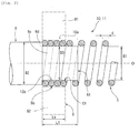
- This glow plug 1A is manufactured as follows. First, a heating coil 5 is prepared, as shown in Figs. 1 and 2 .
- Thematerial of the heating coil 5 is a Co-Ni-Fe alloy, an Fe alloy, an Ni alloy, or the like.
- the inside diameter D1 of the heating coil 5 is 2.6 mm, and its wire diameter d is 0.25 mm.
- a first center pole 8 is prepared.
- the first center pole 8 is a rod-like member extending in the direction of an axis O and is a distal end-side member among a plurality of members making up a center pole 6.
- the material of the first center pole 8 is, for example, SCM435, and a cylindrical inserting portion 8c is formed at a distal end of the first center pole 8, while a large-diameter portion 8d is formed in such a manner as to be contiguous to the rear end of the inserting portion.
- the outside diameter D3 of the inserting portion 8c is 2.65 mm which is slightly larger than the inside diameter D1 of the heating coil 5, and the outside diameter D2 of the large-diameter portion 8d is 2.9 mm which is larger than the total of the inside diameter D1 of the heating coil 5 and the wire diameter d of the heating coil 5.
- the length L1 in the direction of the axis O between a distal end position A1 of the inserting portion 8c and a distal end face of the large-diameter portion 8d is 1.75 mm.
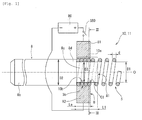
- the inserting portion 8c of the first center pole 8 is inserted into an insertion receiving portion 5b of the heating coil 5, to thereby provide an overlapping portion 10a where the inserting portion 8c of the first center pole 8 and the insertion receiving portion 5b of the heating coil 5 abut against each other and overlap in the radial direction.
- the arrangement provided is such that as the rear end of the heating coil 5 abuts against the distal end face of the large-diameter portion 8d and stops, the overlapping portion 10a of a fixed length is provided.
- the length of the overlapping portion 10a in the direction of the axis O is always equal to the length L1 in the direction of the axis O between the distal end position A1 of the inserting portion 8c and the distal end face of the large-diameter portion 8d. Further, because the outside diameter D3 of the inserting portion 8c is slightly larger than the inside diameter D1 of the insertion receiving portion 5b, the heating coil 5 is in a state in which it tightens the inserting portion 8c. A first glow plug intermediate body 10 is thus obtained.
- the electrodes 81 and 82 are similar to the conventional ones and their length Le in the direction of the axis O is 1.25 mm.
- the length L1 in the direction of the axis O between the distal end position A1 of the inserting portion 8c and the distal end face of the large-diameter portion 8d is extended and set to 1.75 mm although it was substantially identical to the length Le of the electrodes 81 and 82 in the direction of the axis O.
- the setting provided is such that the heating coil 5 is present by a length of 0.5 mm (about one turn) between the distal end face B of each of the electrodes 81 and 82 and the distal end position A1 of the overlapping portion 10a.
- a predetermined load is applied perpendicularly to a portion of the overlapping portion 10a through the electrodes 81 and 82.
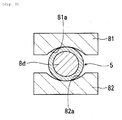
- semicylindrical concave portions 81a and 82a are respectively provided at portions of the electrodes 81 and 82 which come into contact with the insertion receiving portion 5b of the heating coil 5.
- the electrodes 81 and 82 are capable of effecting centering with respect to the insertion receiving portion 5b of the heating coil 5, so that the load can be easily applied to the overlapping portion 10a.
- the electrodes 81 and 82 are connected to a power supply 80 through a switch S80, and as a current is applied across the electrodes 81 and 82 by turning on the switch S80, the inserting portion 8c of the first center pole 8 and the insertion receiving portion 5b of the heating coil 5 are welded together.
- a weld portion 10b is formed such that about one turn of winding (a length of 0.5 mm) of the heating coil 5 in a state of being not welded to the inserting portion 8c of the first center pole 8 is present between a distal end position C1 of the weld portion 10b and the distal end position A1 of the overlapping portion 10a.
- a second glow plug intermediate body 11 in which the first center pole 8 and the heating coil 5 are joined is thus obtained.
- the second glow plug intermediate bodies 11 of Example 1 and the second glow plug intermediate bodies of Comparative Example 1 thus fabricated are each assembled to a metal shell 3 and the like in the same way as the conventional one shown in Fig. 5 , and are respectively formed into the glow plugs 1A of Example 1 and glow plugs 1A' of Comparative Example. Since the assembling procedure and the like are also similar to the conventional one, a description thereof will be omitted.
- the glow plugs 1A and 1A' thus obtained are used in diesel engines.
- the respective electrodes 81 and 82 and the overlapping portion 10a are specified in the above-described first and second steps. Further, about one turn of winding of the heating coil 5 is present between the distal end face B of each of the electrodes 81 and 82 and the distal end position A1 of the overlapping portion 10a.
- the overlapping portion 10a and the weld portion 10b are specified in the above-described first and second steps. Further, about one turn of winding of the heating coil 5 in a state of being not welded to the inserting portion 8c is present between the distal end position C1 of the weld portion 10b and the distal end position A1 of the overlapping portion 10a.
- the method for manufacturing the glow plug 1A of Example 1 it is possible to suppress a defect in quality such as a short-circuit fault and variations in the performance when applying current.
- the glow plug 1A which is obtained by this method for manufacturing the glow plug 1A can be made smaller in diameter, so that it is possible to increase the temperature rise speed and cope with a reduction in the diameter of the glow hole due to the demand for a more compact and lightweight diesel engine.
- the electrodes 81 and 82 are disposed such that three or more turns of winding of the heating coil 5 will not be present between the distal end face B of each of the electrodes 81 and 82 and the distal end position A1 of the overlapping portion 10a.
- the weld portion 10b is formed such that with three or more turns of winding of the heating coil 5 in a state of being not welded to the inserting portion 8c of the first center pole 8 will not be present between the distal end position C1 of the weld portion 10b and the distal end position A1 of the overlapping portion 10a.
- the heating coil 5 can be easily supported by the inserting portion 8c of the first center pole 8 which tightens.
- the axis of the heating coil 5 is further prevented from becoming bent on the distal end side located forwardly of the weld portion 10b.
- the large-diameter portion 8d which is contiguous to the rear end of the inserting portion 8c and has the outside diameter D2 larger than the total of the inside diameter D1 of the insertion receiving portion 5b and the wire diameter d of the heating coil 5, is formed in the first center pole 8.
- the operation of providing the overlapping portion 10a of a fixed length can be easily carried out. As a result, the operating efficiency can be improved.
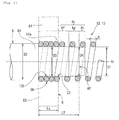
- an inserting portion 8e is adopted which has a cylindrical surface 8f, a first tapered surface 8g contiguous to the distal end side of the cylindrical surface 8f, and a second tapered surface 8h contiguous to the distal end side of the first tapered surface 8g.
- the other arrangements are similar to those of the method for manufacturing the glow plug 1A of Example 1, so that a description thereof will be omitted.
- the first tapered surface 8g becomes smaller in diameter toward its distal end and forms at least a portion of an overlapping portion 12a. Since the outside diameter D4 of a distal end of the first tapered surface 8g is set equal to the inside diameter D1 of the insertion receiving portion 5b, a distal end position A2 of the overlapping portion 12a is the distal end of the first tapered surface 8g. For this reason, when the inserting portion 8e of the first center pole 8 is inserted into the insertion receiving portion 5b of the heating coil 5, the first tapered surface 8g acts so as to guide the inserting portion 8e into the heating coil 5. In addition, the length L2 in the direction of the axis O between the distal end position A2 of the overlapping portion 12a and the distal end face of the large-diameter portion 8d is 2.25 mm.
- the second tapered surface 8h becomes smaller in diameter toward its distal end continuously from the first tapered surface 8g and is smaller in diameter than the inside diameter D1 of the insertion receiving portion 5b. For this reason, the operation of inserting the foremost end of the inserting portion 8e of the first center pole 8 into the insertion receiving portion 5b of the heating coil 5 is further facilitated.
- a first glow plug intermediate body 12 provided with the overlapping portion 12a is obtained in the first step.
- the electrodes 81 and 82 are similar to the conventional ones and their length Le in the direction of the axis O is 1. 25 mm.
- the length L2 in the direction of the axis O between the distal end position A2 of the overlapping portion 12a and the distal end face of the large-diameter portion 8d is further extended and set to 2.25 mm although it was substantially identical to the length Le of the electrodes 81 and 82 in the direction of the axis O.
- the setting provided is such that the heating coil 5 is present by a length of 1.0 mm (about two turns) between the distal end face B of each of the electrodes 81 and 82 and the distal end position A2 of the overlapping portion 12a.
- a portion of the overlapping portion 12a is welded by means of the electrodes 81 and 82 in the same way as in the method for manufacturing the glow plug 1A of Example 1.
- a weld portion 12b is formed such that about two turns of winding (a length of 1.0 mm) of the heating coil 5 in a state of being not welded to the inserting portion 8e of the first center pole 8 are present between a distal end position C2 of the weld portion 12b and the distal end position A2 of the overlapping portion 12a.
- a second glow plug intermediate body 13 in which the first center pole 8 and the heating coil 5 are joined is thus obtained.
- This second glow plug intermediate body 13 is also formed into the glow plug 1B in the same way as the second glow plug intermediate body 11 of Example 1.
- the respective electrodes 81 and 82 and the overlapping portion 12a are specified in the above-described first and second steps. Further, about two turns of winding of the heating coil 5 are present between the distal end face B of each of the electrodes 81 and 82 and the distal end position A2 of the overlapping portion 12a.
- the overlapping portion 12a and the weld portion 12b are specified in the above-described first and second steps. Further, about two turns of winding of the heating coil 5 in a state of being not welded to the inserting portion 8e are present between the distal end position C2 of the weld portion 12b and the distal end position A2 of the overlapping portion 12a.
- the axis of the heating coil 5 is prevented from becoming bent on the distal end side located forwardly of the weld portion 12b for the same reason as that for the second glow plug intermediate body 11 obtained by the manufacturing method according to Example 1.
- the inserting portion 8e of the first center pole 8 has, in addition to the cylindrical surface 8f, the aforementioned first tapered surface 8g and second tapered surface 8h. For this reason, in the first step, the operation of inserting the inserting portion 8e of the first center pole 8 into the insertion receiving portion 5b of the heating coil 5 can be easily carried out. As a result, the operating efficiency can be improved.
- the heating coil is not limited to the case where it is constituted by one member as in the heating coil 5, and the heating coil may be constituted by a plurality of materials having different temperature coefficients of resistance (one having a self-controlling function consisting of a so-called control coil and heating coil).
- the inside diameter D1 of the heating coil 5 described in Examples 1 and 2 suffices if the inside diameter D1 is provided at the insertion receiving portion 5b of the heating coil 5, and the inside diameter at other than the insertion receiving portion 5b may be larger than D1.
- the invention is applicable to a glow plug.
Landscapes
- Engineering & Computer Science (AREA)
- Chemical & Material Sciences (AREA)
- Combustion & Propulsion (AREA)
- Mechanical Engineering (AREA)
- General Engineering & Computer Science (AREA)
- Resistance Heating (AREA)
Applications Claiming Priority (1)
| Application Number | Priority Date | Filing Date | Title |
|---|---|---|---|
| PCT/JP2007/054856 WO2008126171A1 (ja) | 2007-03-12 | 2007-03-12 | グロープラグの製造方法及びグロープラグ |
Publications (1)
| Publication Number | Publication Date |
|---|---|
| EP2136142A1 true EP2136142A1 (de) | 2009-12-23 |
Family
ID=39863354
Family Applications (1)
| Application Number | Title | Priority Date | Filing Date |
|---|---|---|---|
| EP07738328A Withdrawn EP2136142A1 (de) | 2007-03-12 | 2007-03-12 | Verfahren zur herstellung von glühkerzen und glühkerze |
Country Status (4)
| Country | Link |
|---|---|
| US (1) | US20090314761A1 (de) |
| EP (1) | EP2136142A1 (de) |
| CN (1) | CN101365912A (de) |
| WO (1) | WO2008126171A1 (de) |
Cited By (2)
| Publication number | Priority date | Publication date | Assignee | Title |
|---|---|---|---|---|
| EP3333483A1 (de) * | 2016-12-12 | 2018-06-13 | NGK Spark Plug Co., Ltd. | Glühkerze |
| JP2018096670A (ja) * | 2016-12-12 | 2018-06-21 | 日本特殊陶業株式会社 | グロープラグ |
Families Citing this family (3)
| Publication number | Priority date | Publication date | Assignee | Title |
|---|---|---|---|---|
| US20090184101A1 (en) * | 2007-12-17 | 2009-07-23 | John Hoffman | Sheathed glow plug |
| JP5922946B2 (ja) * | 2012-02-22 | 2016-05-24 | 日本特殊陶業株式会社 | グロープラグ |
| JP6426346B2 (ja) * | 2014-01-16 | 2018-11-21 | 日本特殊陶業株式会社 | グロープラグ |
Family Cites Families (3)
| Publication number | Priority date | Publication date | Assignee | Title |
|---|---|---|---|---|
| JPH0415408A (ja) * | 1990-05-09 | 1992-01-20 | Ngk Spark Plug Co Ltd | シーズ型グロープラグ |
| JPH05332539A (ja) * | 1992-06-01 | 1993-12-14 | Jidosha Kiki Co Ltd | シーズヒータおよびその製造方法 |
| JP4373183B2 (ja) * | 2003-10-31 | 2009-11-25 | 日本特殊陶業株式会社 | グロープラグの製造方法 |
-
2007
- 2007-03-12 EP EP07738328A patent/EP2136142A1/de not_active Withdrawn
- 2007-03-12 WO PCT/JP2007/054856 patent/WO2008126171A1/ja not_active Ceased
- 2007-03-12 CN CNA2007800004706A patent/CN101365912A/zh active Pending
- 2007-03-12 US US11/915,932 patent/US20090314761A1/en not_active Abandoned
Non-Patent Citations (1)
| Title |
|---|
| See references of WO2008126171A1 * |
Cited By (2)
| Publication number | Priority date | Publication date | Assignee | Title |
|---|---|---|---|---|
| EP3333483A1 (de) * | 2016-12-12 | 2018-06-13 | NGK Spark Plug Co., Ltd. | Glühkerze |
| JP2018096670A (ja) * | 2016-12-12 | 2018-06-21 | 日本特殊陶業株式会社 | グロープラグ |
Also Published As
| Publication number | Publication date |
|---|---|
| CN101365912A (zh) | 2009-02-11 |
| US20090314761A1 (en) | 2009-12-24 |
| WO2008126171A1 (ja) | 2008-10-23 |
Similar Documents
| Publication | Publication Date | Title |
|---|---|---|
| EP1926189A1 (de) | Zündkerze | |
| US20090314761A1 (en) | Method for manufacturing glow plug and glow plug | |
| JP5757828B2 (ja) | グロープラグ及びその製造方法 | |
| EP2833492B1 (de) | Zündkerze | |
| JP4870640B2 (ja) | グロープラグおよびその製造方法 | |
| JP5455522B2 (ja) | グロープラグ及びその製造方法 | |
| US20050093412A1 (en) | Spark plug center electrode assembly | |
| KR101638723B1 (ko) | 글로 플러그 | |
| KR101603468B1 (ko) | 글로 플러그 및 그 제조방법 | |
| EP2116772B1 (de) | Verfahren zum herstellen eines glühstiftes | |
| JP4123668B2 (ja) | グロープラグの製造方法 | |
| KR101679945B1 (ko) | 글로 플러그 및 그 제조방법 | |
| JP5525051B2 (ja) | グロープラグ | |
| JP4480663B2 (ja) | グロープラグの製造方法及びグロープラグ | |
| KR20090127448A (ko) | 글로우 플러그의 제조방법 및 글로우 플러그 | |
| JP4309757B2 (ja) | セラミックヒーター | |
| US11990731B2 (en) | Spark plug electrode and method of manufacturing same | |
| JP4871193B2 (ja) | グロープラグ及びその製造方法 | |
| JP4695536B2 (ja) | グロープラグ | |
| JP4510588B2 (ja) | グロープラグ | |
| JP4342289B2 (ja) | スパークプラグ用主体金具の製造方法及びスパークプラグの製造方法 | |
| EP3396249B1 (de) | Glühkerze | |
| JP7004456B2 (ja) | ヒータの製造方法及びヒータ | |
| JP6720039B2 (ja) | グロープラグ | |
| JP2001155840A (ja) | スパークプラグの製造方法 |
Legal Events
| Date | Code | Title | Description |
|---|---|---|---|
| PUAI | Public reference made under article 153(3) epc to a published international application that has entered the european phase |
Free format text: ORIGINAL CODE: 0009012 |
|
| 17P | Request for examination filed |
Effective date: 20071130 |
|
| AK | Designated contracting states |
Kind code of ref document: A1 Designated state(s): DE FR |
|
| DAX | Request for extension of the european patent (deleted) | ||
| STAA | Information on the status of an ep patent application or granted ep patent |
Free format text: STATUS: THE APPLICATION IS DEEMED TO BE WITHDRAWN |
|
| 18D | Application deemed to be withdrawn |
Effective date: 20100413 |