EP2136120A1 - Collier de serrage à ergot d'accrochage embouti - Google Patents
Collier de serrage à ergot d'accrochage embouti Download PDFInfo
- Publication number
- EP2136120A1 EP2136120A1 EP09162820A EP09162820A EP2136120A1 EP 2136120 A1 EP2136120 A1 EP 2136120A1 EP 09162820 A EP09162820 A EP 09162820A EP 09162820 A EP09162820 A EP 09162820A EP 2136120 A1 EP2136120 A1 EP 2136120A1
- Authority
- EP
- European Patent Office
- Prior art keywords
- lug
- strip
- boss
- ear
- common
- Prior art date
- Legal status (The legal status is an assumption and is not a legal conclusion. Google has not performed a legal analysis and makes no representation as to the accuracy of the status listed.)
- Granted
Links
- 239000002184 metal Substances 0.000 claims abstract description 8
- 238000000034 method Methods 0.000 claims abstract description 6
- 238000004519 manufacturing process Methods 0.000 claims description 3
- 238000004873 anchoring Methods 0.000 abstract 2
- 210000005069 ears Anatomy 0.000 description 4
- 230000015572 biosynthetic process Effects 0.000 description 3
- 230000005484 gravity Effects 0.000 description 3
- 239000000463 material Substances 0.000 description 3
- 238000005096 rolling process Methods 0.000 description 2
- 238000005482 strain hardening Methods 0.000 description 2
- 230000003313 weakening effect Effects 0.000 description 2
- 230000005540 biological transmission Effects 0.000 description 1
- 210000000080 chela (arthropods) Anatomy 0.000 description 1
- 238000004140 cleaning Methods 0.000 description 1
- 230000003247 decreasing effect Effects 0.000 description 1
- 230000010339 dilation Effects 0.000 description 1
- 230000000694 effects Effects 0.000 description 1
- 238000005259 measurement Methods 0.000 description 1
- 238000004804 winding Methods 0.000 description 1
Images


Classifications
-
- B—PERFORMING OPERATIONS; TRANSPORTING
- B65—CONVEYING; PACKING; STORING; HANDLING THIN OR FILAMENTARY MATERIAL
- B65D—CONTAINERS FOR STORAGE OR TRANSPORT OF ARTICLES OR MATERIALS, e.g. BAGS, BARRELS, BOTTLES, BOXES, CANS, CARTONS, CRATES, DRUMS, JARS, TANKS, HOPPERS, FORWARDING CONTAINERS; ACCESSORIES, CLOSURES, OR FITTINGS THEREFOR; PACKAGING ELEMENTS; PACKAGES
- B65D63/00—Flexible elongated elements, e.g. straps, for bundling or supporting articles
- B65D63/02—Metallic straps, tapes, or bands; Joints between ends thereof
-
- F—MECHANICAL ENGINEERING; LIGHTING; HEATING; WEAPONS; BLASTING
- F16—ENGINEERING ELEMENTS AND UNITS; GENERAL MEASURES FOR PRODUCING AND MAINTAINING EFFECTIVE FUNCTIONING OF MACHINES OR INSTALLATIONS; THERMAL INSULATION IN GENERAL
- F16L—PIPES; JOINTS OR FITTINGS FOR PIPES; SUPPORTS FOR PIPES, CABLES OR PROTECTIVE TUBING; MEANS FOR THERMAL INSULATION IN GENERAL
- F16L33/00—Arrangements for connecting hoses to rigid members; Rigid hose connectors, i.e. single members engaging both hoses
- F16L33/02—Hose-clips
- F16L33/035—Hose-clips fixed by means of teeth or hooks
-
- B—PERFORMING OPERATIONS; TRANSPORTING
- B65—CONVEYING; PACKING; STORING; HANDLING THIN OR FILAMENTARY MATERIAL
- B65D—CONTAINERS FOR STORAGE OR TRANSPORT OF ARTICLES OR MATERIALS, e.g. BAGS, BARRELS, BOTTLES, BOXES, CANS, CARTONS, CRATES, DRUMS, JARS, TANKS, HOPPERS, FORWARDING CONTAINERS; ACCESSORIES, CLOSURES, OR FITTINGS THEREFOR; PACKAGING ELEMENTS; PACKAGES
- B65D63/00—Flexible elongated elements, e.g. straps, for bundling or supporting articles
- B65D63/02—Metallic straps, tapes, or bands; Joints between ends thereof
- B65D63/04—Joints produced by deformation of ends of elements
-
- F—MECHANICAL ENGINEERING; LIGHTING; HEATING; WEAPONS; BLASTING
- F16—ENGINEERING ELEMENTS AND UNITS; GENERAL MEASURES FOR PRODUCING AND MAINTAINING EFFECTIVE FUNCTIONING OF MACHINES OR INSTALLATIONS; THERMAL INSULATION IN GENERAL
- F16B—DEVICES FOR FASTENING OR SECURING CONSTRUCTIONAL ELEMENTS OR MACHINE PARTS TOGETHER, e.g. NAILS, BOLTS, CIRCLIPS, CLAMPS, CLIPS OR WEDGES; JOINTS OR JOINTING
- F16B2/00—Friction-grip releasable fastenings
- F16B2/02—Clamps, i.e. with gripping action effected by positive means other than the inherent resistance to deformation of the material of the fastening
- F16B2/06—Clamps, i.e. with gripping action effected by positive means other than the inherent resistance to deformation of the material of the fastening external, i.e. with contracting action
- F16B2/08—Clamps, i.e. with gripping action effected by positive means other than the inherent resistance to deformation of the material of the fastening external, i.e. with contracting action using bands
-
- F—MECHANICAL ENGINEERING; LIGHTING; HEATING; WEAPONS; BLASTING
- F16—ENGINEERING ELEMENTS AND UNITS; GENERAL MEASURES FOR PRODUCING AND MAINTAINING EFFECTIVE FUNCTIONING OF MACHINES OR INSTALLATIONS; THERMAL INSULATION IN GENERAL
- F16L—PIPES; JOINTS OR FITTINGS FOR PIPES; SUPPORTS FOR PIPES, CABLES OR PROTECTIVE TUBING; MEANS FOR THERMAL INSULATION IN GENERAL
- F16L33/00—Arrangements for connecting hoses to rigid members; Rigid hose connectors, i.e. single members engaging both hoses
- F16L33/02—Hose-clips
-
- Y—GENERAL TAGGING OF NEW TECHNOLOGICAL DEVELOPMENTS; GENERAL TAGGING OF CROSS-SECTIONAL TECHNOLOGIES SPANNING OVER SEVERAL SECTIONS OF THE IPC; TECHNICAL SUBJECTS COVERED BY FORMER USPC CROSS-REFERENCE ART COLLECTIONS [XRACs] AND DIGESTS
- Y10—TECHNICAL SUBJECTS COVERED BY FORMER USPC
- Y10T—TECHNICAL SUBJECTS COVERED BY FORMER US CLASSIFICATION
- Y10T24/00—Buckles, buttons, clasps, etc.
- Y10T24/14—Bale and package ties, hose clamps
- Y10T24/1457—Metal bands
- Y10T24/1478—Circumferentially swagged band clamp
-
- Y—GENERAL TAGGING OF NEW TECHNOLOGICAL DEVELOPMENTS; GENERAL TAGGING OF CROSS-SECTIONAL TECHNOLOGIES SPANNING OVER SEVERAL SECTIONS OF THE IPC; TECHNICAL SUBJECTS COVERED BY FORMER USPC CROSS-REFERENCE ART COLLECTIONS [XRACs] AND DIGESTS
- Y10—TECHNICAL SUBJECTS COVERED BY FORMER USPC
- Y10T—TECHNICAL SUBJECTS COVERED BY FORMER US CLASSIFICATION
- Y10T24/00—Buckles, buttons, clasps, etc.
- Y10T24/14—Bale and package ties, hose clamps
- Y10T24/1457—Metal bands
- Y10T24/148—End-to-end integral band end connection
-
- Y—GENERAL TAGGING OF NEW TECHNOLOGICAL DEVELOPMENTS; GENERAL TAGGING OF CROSS-SECTIONAL TECHNOLOGIES SPANNING OVER SEVERAL SECTIONS OF THE IPC; TECHNICAL SUBJECTS COVERED BY FORMER USPC CROSS-REFERENCE ART COLLECTIONS [XRACs] AND DIGESTS
- Y10—TECHNICAL SUBJECTS COVERED BY FORMER USPC
- Y10T—TECHNICAL SUBJECTS COVERED BY FORMER US CLASSIFICATION
- Y10T24/00—Buckles, buttons, clasps, etc.
- Y10T24/14—Bale and package ties, hose clamps
- Y10T24/1457—Metal bands
- Y10T24/1482—Ratchet and tool tightened band clamp
Definitions
- the present invention relates to a clamp made from a metal strip wound on itself, comprising a hooking lug formed radially projecting outwardly near the first end of the band and an ear, formed radially outwardly in the vicinity of the second end of the strip and having a lumen into which a free end portion of the lug can be inserted for hooking and clamping the collar while the ear capping a foot portion of the lug, the collar further having gripping surfaces for a gripping tool, which project radially outwardly and are respectively located at the back of the ear and at the rear of the lug.
- a collar of this type is known by US 4,713,863 .
- the hooking lug is formed at the top of a first ear, while the light in which this pin penetrates to achieve the attachment is formed on the top of a second ear.
- These ears have a generally L-shaped overturned and are made by successive folds, which extend transversely over the entire width of the strip.
- the height of the ears measured from the plane of the band, is of the order of 2/3 of the radius of the collar.
- the ears are very flexible so that the collar has a relatively low overall stiffness.
- the large radial height of the ears may be a disadvantage for some applications, especially when the collar is used to tighten a rotating part, because the center of gravity of the collar is very far from the geometric center of the circle that forms the collar band when it is closed.
- EP 0 846 906 discloses another collar of the aforementioned type, wherein the hooking lug is formed by a double radial fold which extends transversely over the entire width of the strip. To stiffen this double fold, stiffening ribs are formed at the foot of the pin. However, the rib which is located at the rear of the lug forms a ramp which is an inconvenience for the engagement of a pincer clamping tool with the foot of the lug.
- the ear has a generally L-shaped overturned shape, and is formed by a succession of folds that extend transversely over the entire width of the strip. The ear is stiffened in the elbow of the L by a rib.
- stiffenings foot of the lug and elbow of the ear
- the ear and the hooking lug have a radial height of the order of half the radius of the circle formed by the collar when closed. This very significant radial height may also deport the center of gravity with respect to the geometric center of the aforementioned circle, which poses difficulties previously mentioned when the collar is intended to tighten a rotating part.
- the object of the invention is to improve the state of the prior art by ensuring that the hooking lug can be extremely rigid, without this rigidity being acquired to the detriment of the gripping surface situated at the rear of this device. ergot, and while allowing the pin can have a low radial height.
- the lug being formed in the common boss, it has a high rigidity. Indeed, the boss is obtained by a process of the stamping type, and not by transverse folds extending over the entire width of the strip. As a result, its rigidity is much greater than that of a shape that would be obtained by transverse bends.
- the lug is attached to the portion of the boss that carries the gripping surface by the side cheeks that contribute greatly to its rigidity.
- being formed by a boss it may have a low radial height.
- the lug has a free hooking end formed by the edge of a blank, the common lateral cheeks extending on the respective sides of the lug between the plane of the band and an end of the edge of the blank. the cut.
- the edge of the cut offers a possibility of attachment, in the light of the ear, which is both easy to obtain and extremely reliable.
- the clamping collar has lateral margins extending, in the plane of the band, on either side of the common lateral cheeks.
- these lateral margins further stiffens the common boss.
- they Preferably, they have a width of the order of at least about 1/8 th , preferably between 1/7 th and 1/5 th , of the total width of the band.
- the lug has a maximum radial height at most substantially equal to the maximum radial height of the portion of the common boss in which is formed the gripping surface located at the rear of the lug, and the common boss has a recess at the rear of the lug, adjacent to said lug.
- the lug is located in the radial space of the common boss and the recess located at the rear of the lug allows the front edge of the light of the hooking ear to be placed in front of the ergot, at a height less than the maximum radial height of the latter, to achieve a reliable attachment.
- the lug can thus be made on a very small radial height.
- the ear has a front portion in which the light is formed and which is close to the plane of the band relative to a rear part of the ear.
- the light of the ear has a leading edge which is substantially located in the plane of the band.
- the ear is formed by an ear boss, on either side of which are formed lateral margins which extend substantially in the plane of the strip. These arrangements also allow the ear to be performed on a very low radial height. In addition, it has a high rigidity due to its formation in a boss made for example by stamping.
- the invention also aims to provide a clamping collar in which the clamping is obtained by hooking a hooking lug on a hooking lug radially projecting, providing continuity of support of the collar on the object to be tightened by this collar, even under the ear, in which are provided pre-latching means for closing the collar and to maintain it in the closed state when the ear is not hooked on the pin, and wherein the amount of material used is limited. In particular, it is necessary to prevent the band from being too long in relation to the diameter of the collar.
- the first end of the strip has a flap which extends to the front of the lug and which carries a pre-latching projection
- the second end of the strip has, at the back of the ear, a longitudinal pre-latching slot in which said projection is engaged to pre-hook the collar, and the pre-latching projection is formed in a free end portion of the flap having a width less than the width of the strip, while the pre-latching slot extends , away from the ear, at least to an internal recess adapted to receive said free end portion of the flap.
- the flap serves both to achieve the pre-latching and the continuity of support on the object to be tightened.
- the pre-latching projection is formed at the free end of this flap, it may have just the length required for this purpose.
- this free end portion of the flap in which is formed the pre-latching projection engages in the internal recess to avoid a discontinuity of the support at the free end of this bib.
- the internal recess has sides that are substantially in the plane of the strip, so that the free end of the flap has a width less than the width of the strip to fit between these sides.
- the pre-latching projection is formed by a tongue, cut in the strip and straightened, and the cutout in which the tongue is formed is offset relative to a median longitudinal axis of the strip.
- the pretensioning projection being cut in the free end portion of the flap which has a reduced width relative to that of the strip, the fact of shifting the above-mentioned cutout with respect to a median longitudinal axis of the strip makes it possible to make a tongue of sufficient length to, once straightened, have the required height of projection, without the edges of the cut are too close to the longitudinal edges of the flap.
- the pre-latching slot may have a relatively large width, while remaining centered on the median longitudinal axis of the strip, to receive this offset pre-latching projection.
- the pre-latching slot is also offset with respect to said longitudinal axis, in the same direction as the cutout in which the tongue is formed.
- the width of the pre-fastening strip may be substantially equal to the thickness of the strip, which is also the thickness of the pre-fastening protrusion so that this slot does not substantially limit the rigidity of the collar.
- the invention also relates to a method for producing a clamping collar, in which a strip of metal is provided, a hooking lug projecting radially outwardly in the vicinity of the first end of the strip is produced.
- a hooking lug projecting radially outwardly in the vicinity of the first end of the strip is produced.
- an ear projecting radially outwardly in the vicinity of the second end of the band, an ear having a light in which can be inserted a free end portion of the lug for hooking and tightening the collar while the The ear covers a portion of the foot of the lug, gripping surfaces for a gripping tool are produced that project radially outwards and are located respectively at the back of the ear and at the rear of the lug. ergot, and we roll the tape on itself.
- the aim of the invention is to provide a method for producing a collar whose pre-latching pin may have a small radial height, while being extremely rigid, and without impairing the quality of the tool grip on the surface of the device. socket located at the rear of this pin. At the same time, it is to achieve this pin and the aforementioned socket surface simply, economically and reliably.
- the common boss can be made in a simple manner, having both the lug and the gripping surface located at the rear of the latter, so that the lug has a high rigidity.
- the fact of preserving the aforementioned lateral cheeks makes it possible to further stiffen the boss.
- the common boss is formed by forming the lug in a front part of this common boss, forming the hooking surface in a rear part of this boss and cleaning, to the rear of the lug, a recess adjacent this lug.
- the lug can be made particularly simple while being extremely rigid.
- a substantially transverse cut is made in the common boss, so as to delimit said front and rear portions of this boss on either side of the cut.
- the edge of the cut on the side of the lug then forms a hooking surface for the corresponding edge of the light of the ear, which promotes an extremely reliable attachment.
- the front portion of the intermediate common boss is raised and a rear end portion of the rear portion of the boss is raised.
- common intermediate forming, in said rear portion, the recess adjacent to the lug.
- the common boss may initially be made on a very small radial height in a first tool path. In a second pass, one can at the same time raise the front part of the common boss and the rear part of this boss forming the recess between the two. The aforementioned cut, if present, can be performed in the same second tool pass.
- the clamp according to the invention is made from a metal strip 1 wound on itself.
- This is a metal type conventional, the strip being cut in particular from a strip suitable for producing the clamps. It can be seen that, even in the uncompressed state of the necklace represented on the figure 1 , the band is wound on itself over 360 °, so that the two ends of this band overlap.
- the overlapping angular range can be 20 ° (for a diameter of the order of 100 mm or more) to 90 ° (for a diameter of about 20 mm) .
- a hooking lug 10 is formed protruding radially outwardly near the first end 1A of the strip.
- a hooking lug 12 is formed radially outwardly in the vicinity of the second end 1B of the strip.
- the plane of the strip corresponds to the zones of the strip wound on itself, not deformed outwards or inwards. So, "the plan of the band” is on the figure 2 materialized by a circle C defined by the collar, having a geometric center O.
- the “outward” meaning means the direction going away from this geometric center or opposite to this geometric center.
- the inner face of the band is the one facing the center O, while the outer face is the opposite side.
- the ear 12 has a slot 13 in which is inserted the pin 10 in the tight state of the collar.
- the free edge 10A of the lug cooperates with the front edge 13A of the light.
- the light 13 has a length, measured in the longitudinal direction of the strip, which is sufficient so that, in the tight state, the entire head 10B of the lug 10 passes into this light 13.
- it only a free end portion of the lug, in which the maximum height H of this lug is measured by ratio to the plane of the band exceeds in this light.
- the ear covers a foot portion 10C of the lug, that is to say that, considered with respect to the ear, this foot portion is located behind the rear edge 13B of the ear.
- the collar has gripping surfaces for a clamping tool which also project radially outwardly.
- This tool being in particular of the clamp type, it has shown in broken lines its two jaws, 2A and 2B. We thus see a first engaging surface 14 located behind the lug 10 and a second engaging surface 16 located behind the lug 12.
- the lug 10 and the engaging surface 14 are formed in a common boss 18. They have side cheeks 20, which are raised relative to the plane of the strip and are common to them. These lateral cheeks extend on each of the two longitudinal sides of the common boss 18. On the figure 2 it can be seen that the lateral cheeks 20 extend, on the respective sides of the lug, between the plane C of the band and an end 10'A of the edge of the cut forming the hooking edge 10A of the lug . We also see that these lateral cheeks extend over a height h which is advantageously of the order of at least substantially 1/4 of the maximum height H of the pin, for example of the order of 1/3 of this maximum height.
- figure 2 shows only one of the side cheeks, as it is a side view of the necklace.
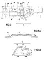
- the conformation is similar on the other side, the common boss being symmetrical with respect to the median longitudinal axis A of the band, as can be seen in particular on the figure 3 , on which we also note that the ear 12 is also symmetrical with respect to this axis A.
- the edge of the blank 10A has a convex shape when viewed from above. This promotes the attachment on the edge 13A of the light 13 of the ear.
- the collar has lateral margins 22 which extend on either side of the common lateral cheeks 20. As can be better understood by considering the figure 2 these lateral margins 22 extend in the plane C of the band.
- the width I of each lateral margin 22 is substantially equal to 1/7 th or more of the width L of the strip at the location of the measurement. We notice on the figure 3 than, in the central region of the common boss 18, the width of the strip is locally decreased.
- the deformed material for producing the boss has a thickness which is not significantly reduced with respect to the thickness e of the strip. This is particularly important in the middle region of the common boss 18, in which is the junction zone between the lug 10 and the rear portion of the boss, and in which the fact of obtaining a high rigidity is particularly important.
- the lug 10 is formed in a portion of the common boss 18 which is narrower than the tooling surface 14 located at the rear of the lug.
- the width LE of the lug 10 is substantially equal to 2/3 of the width LP of the gripping surface 14. This makes it possible to obtain a very wide gripping surface, giving sufficient grip to the tightening tool, while achieving a hooking lug 10 of lesser width, allowing it to be capped by the lug 12, itself formed by a boss that does not extend over the entire width of the strip.
- the gripping surfaces 14 and 16 have the bowl-like shapes, which favors the gripping of the gripper-like tool.
- the maximum radial height H of the lug 10 is substantially equal to the maximum radial height H 'of the common boss portion 18 in which the engaging surface 14 is formed.
- the heights H and H' are advantageously of the order from 2 to 5 mm, preferably of the order of 2.5 to 3 mm, for a collar whose strip has a thickness of the order of 0.6 to 0.8 mm. It should be noted that, to promote attachment, the height H may be slightly greater than the height H '.
- the term "substantially equal” covers the fact that H is between H 'and 1.3.H', preferably between 1.1H and 1.1H.
- the common boss has a recess 24 at the rear of the lug, adjacent to this lug. Indeed, the bottom of the recess 24 starts at the base of the free edge 10A of the lug. From this plumb, the recess goes back to the height H '. This recess thus provides, immediately behind the spigot, the clearance necessary for the edge 10B of the lumen 13 formed in the lug 12 to be placed under the edge 10A of the lug 10. The material remains present in the recess 24, so as to avoid any weakening of the common boss 18, the only cut is the incision of the common boss, which serves to form the edge 10A of the lug 10.
- the ear 12 has a front portion 12A, which is the one in which the light 13 is formed, which is close to the plane C of the band relative to the rear portion 12B of this ear.
- this rear portion 12 is, like the rear portion of the boss 18, sufficiently raised relative to the plane of the strip so that the engagement surfaces 14 and 16 have a sufficient height, substantially equal to the height H 'above, as well for the boss 18 that for the ear 12.
- the ear in its front portion 12A, the ear is profiled to approach the plane of the band, so as to achieve the attachment to a minimum radial height.
- the free end portion 1'B of the second end 1B of the strip has a slightly raised central portion 26, to match the slope of the recess 24 and come to wedge laterally on the latter.
- the width of this central portion 26 raised is slightly greater than the width LE of the lug 10 and corresponds to the width of the outer face of the recess 24, so that when the ear comes to cap this lug during the hanging, it self-center on this lug, then on this recess.
- the approximation of the front portion 12A of the ear relative to the plane is such that the front edge 13A of the light 13 is substantially located in the plane of the strip.
- the head 10B of the lug 10 is in turn substantially flat or, more specifically, it has an outer surface substantially parallel to the plane of the strip. There is thus the demarcation between the foot 10C of the pin and the head 10B of the latter, a work hardening favoring the rigidity of the pin.
- the first end 1A of the band 1 has a flap 28 which extends to the front of the lug. More specifically, this flap 28 extends between the lug 10 and the free end 1'A of the strip. This flap has a projection 30 which serves to pre-hook the collar. Indeed, the second end 1B of the band 1 has, at the rear of the ear, a longitudinal pre-latching slot 32 in which the projection 30 is engaged to achieve a pre-latching of the collar.
- this projection 30 is formed in a free end portion 28A of the flap 28, whose width LS is less than the nominal width LB of the strip.
- This nominal width is the current width of the strip in the regions in which its width is not reduced by the presence of the boss, as has been mentioned with reference to the figure 3 .
- the pre-latching slot 32 extends, away from the ear 12, at least to an internal recess 34.
- This is a recess on the inner face of the collar, facing the geometric center O, while its delimitation forms a boss on the outer side of the band, as seen on the figure 5 .
- the width L34 of the internal recess 34 is adapted to receive the free end portion 28A of the flange in the tightened state of the collar.
- the depth of the internal recess 34 is substantially equal to the thickness of the strip, so that, when the free end portion 28A of the flap is disposed in this recess, the inner face of the flap and the internal faces of the margins 35 of the recess 34 are located on the same circle. There is thus a continuity of support on the object to be clamped by the collar.
- the projection 30 being located in this free end portion 28, in the immediate vicinity of the free end 1'A of the strip, it is not necessary to significantly extend the flap beyond this projection 30, so that the length of the band is calculated to the fairest.
- the pre-hooking protrusion 30 is formed by a tongue, which is cut in the strip (the inner face of the corresponding cutout 36 is seen on the figure 1 ). This tongue remains attached to the band by one of its longitudinal edges 30A (see figure 1 ) according to which it is folded to be radially straightened.
- the width LF of the slot 32 being substantially equal to the thickness of the strip, that is to say to the width of the foot of the projection 30, the free end 30B of this projection, formed from of the tongue, is folded to prevent the projection 30 comes out of the slot inwardly.
- the total width LD of the cutout 36 in which the tongue forming the protrusion 30 is made is of the order of 3 times the thickness of the strip. In this way, the length of the tongue in which the projection 30 is formed is sufficient for this tongue can pass through the slot 32, being folded at its free end 30B to form the projection 30.
- the cutout 36 in which the aforementioned tongue is formed is offset with respect to the median longitudinal axis A of the strip.
- the edge 30A of this cutout through which the tongue is attached to the strip is not on this axis A, but at a distance D of the axis in question.
- the foot of the projection 30 is thus offset laterally with respect to the median longitudinal axis of the strip. This ensures that, although the cutout 36 is formed in the free end portion 28A of the flap whose width LS is reduced relative to the nominal width LB of the strip, this cutout does not come too close to longitudinal edges of the band.
- the longitudinal edges 30A and 36A of the cutout 36 are substantially equidistant from the longitudinal edges of the strip in the free end portion 28A. This distance d is equal to about 1/4 to 1/3 of the nominal width LB of the strip. This prevents the presence of the cutout 36 from weakening the mechanical strength of the strip in the region in which it is formed.
- the slot 32 is also not centered on the median longitudinal axis A of the strip. Indeed, the bandwidths LF1 and LF2 measured on either side of the slot 32 are unequal. The difference between these two widths is substantially equal to the offset distance D of the edge 30A of the cut 36 above.
- the pre-hooking used to maintain the collar in the closed state even before it is tightened can be achieved by calculating at the most just the length of the band, and by determining the width LF of the slot 32 optimally, for avoid too large a width that would locally weaken the mechanical strength of the band.
- the strip has, between the common boss 18 and the lug 12, more precisely between the common boss 18 and the internal recess 34, a central slot 40, on either side of which transverse corrugations 42 are formed. , 44 in opposition of phase.
- These undulations form waves projecting radially from the plane of the strip.
- the peaks of the corrugations 42 correspond to the valleys of the corrugations 44.
- the corrugations form reserves of elasticity or capacity, making it possible to increase the length collar, once tightened, to adapt the clamping force to dilations of the object clamped by the collar, especially under the effect of temperature changes. This arrangement in opposition of phase makes it possible to avoid a discontinuity of support under the undulations.
- the fact of choosing a large number of waves in wave makes it possible to obtain a large reserve of capacity, while realizing these undulations with a low radial height, for example of the same order of magnitude as the heights H and H 'above, ie 2 to 5 mm, preferably 2 to 3 mm for a collar whose strip has a thickness of 0.6 to 0.8 mm.
- the ear 12 is formed by an ear boss, on either side of which are formed lateral margins 12 'which extend substantially in the plane of the band. This conformation reinforces the rigidity of the ear. Of course, the width of the ear, measured on its inner face, is sufficient for the latter to cap the foot of the boss 10. According to the method of the invention, the metal strip 1 is provided, it is carried out. hook 10 and the lug 12 projecting radially outwardly, this ear is equipped with light 13, the gripping surfaces 14 and 16 are made and the tape is wound on itself. It is possible to carry out some of the above-mentioned steps while the strip is flat, or to wind it up during the formation steps.
- the bosses are at least partly made while the strip is flat, and the longitudinal margins formed on either side of the common boss 18 and on either side of the lug 12 serve as surfaces of rolling, facilitating the winding of the band.
- the common boss 18 is formed which has side cheeks 20 raised with respect to the plane of the strip.
- FIGS. 6A and 6B show two successive steps of formation of the common boss 18, with the lug 10 and the gripping surface 14.
- a first pass it produces an intermediate common boss 18 'on a height h' lower than the final height H 'of the boss common.
- a front portion of the intermediate common boss 18 ' is raised to form the lug 10
- a rear portion of this intermediate common boss is raised to form the gripping surface 14, while providing a recess 24 between the lug 10 and the gripping surface 14.
- the height of the base of the recess 24, which is the height h of the common lateral cheeks 20, is substantially equal to the height h 'of the intermediate common boss.
- the front portion of the intermediate boss 18 ' it is sufficient to raise the front portion of the intermediate boss 18 ', while practicing the cut which serves to spare the hooking edge 10A of the lug, and to raise the rear portion of the boss intermediate common 18 'progressively, thereby forming the recess 24.
- the cut forming the attachment edge 10A is made substantially transversely, except that it may have a convex shape, as can be seen in particular on the figure 3 .
- the front portions 19A and rear 19B of the common boss 18 are delimited on either side of this cut.
- the common boss 18 ' can be made flat, while the following steps of realization of the boss 18 can be made flat or, at least in part, while the strip has already been wound.
- the cut is made 36, and the tongue thus formed is folded substantially perpendicular to the plane of the strip.
- the strip is then rolled so as to pass this straightened tongue through the slot, and then the free end portion of the tongue is folded at the end of rolling.
- the flap 28 has longitudinal stiffening ribs.
- these ribs are formed to project on the inner face of the strip. the band. They could however also be formed in external projection.
- the rear end 46A of the central rib 46 remote from the free end 1'A of the strip, slightly encroaches on the foot 10C of the hooking peg 10. As a result, at the base of this foot, an important work hardening which strengthens the rigidity of the pin 10.
- the ribs 48 extend rearwardly, that is to say away from the free end 1'A, along the side cheeks of the common boss 18. Their rear ends 48A are located slightly beyond the zone of attachment of the cut forming the free edge 10A of the lug with the side cheeks 20. This reinforces the rigidity of these cheeks side and avoids the risk of tearing on the sides of the cut in question.
- the collar of the invention is suitable for any use in which an effective and simple to implement clamping is sought, together with a small radial size of the collar.
- the collar can for example be used for clamping a pipe on a nozzle, in the engine compartment of a vehicle, or for tightening a bellows, for example a steering column bellows.
- the collar of the invention is particularly suitable for clamping rotating parts such as transmission bellows. Indeed, its center of gravity is very close to the geometric center of the circle that it forms and its tightening is effected by hooking, very reliably.
Abstract
Description
- La présente invention concerne un collier de serrage réalisé à partir d'une bande de métal enroulée sur elle-même, comprenant un ergot d'accrochage formé en saillie radiale vers l'extérieur au voisinage de la première extrémité de la bande et une oreille, formée en saillie radiale vers l'extérieur au voisinage de la deuxième extrémité de la bande et présentant une lumière dans laquelle peut être insérée une partie d'extrémité libre de l'ergot pour l'accrochage et le serrage du collier alors que l'oreille coiffe une partie de pied de l'ergot, le collier présentant en outre des surfaces de prise pour un outil de serrage, qui sont en saillie radiale vers l'extérieur et sont respectivement situées à l'arrière de l'oreille et à l'arrière de l'ergot.
- Un collier de ce type est connu par
US 4,713,863 . Dans ce collier, l'ergot d'accrochage est formé au sommet d'une première oreille, tandis que la lumière dans laquelle pénètre cet ergot pour réaliser l'accrochage est formée sur le sommet une deuxième oreille. Ces oreilles ont une forme globalement en L renversé et sont réalisées par des plis successifs, qui s'étendent transversalement sur toute la largeur de la bande. De plus, la hauteur des oreilles, mesurée à partir du plan de la bande, est de l'ordre des 2/3 du rayon du collier. Il en résulte que les oreilles sont très flexibles de sorte que le collier présente une rigidité globale relativement faible. De plus, la grande hauteur radiale des oreilles peut présenter un inconvénient pour certaines applications, en particulier lorsque le collier sert à serrer une pièce rotative, car le centre de gravité du collier est très éloigné du centre géométrique du cercle que forme la bande du collier lorsque celui-ci est fermé. -
EP 0 846 906 divulgue un autre collier du type précité, dans lequel l'ergot d'accrochage est formé par un double pli radial qui s'étend transversalement sur toute la largeur de la bande. Pour rigidifier ce double pli, des nervures de rigidification sont formées au pied de l'ergot. Toutefois, la nervure qui est située à l'arrière de l'ergot forme une rampe qui constitue une gêne pour la venue en prise d'un outil de serrage du genre pince avec le pied de l'ergot. L'oreille présente une forme globalement en L renversé, et est formée par une succession de plis qui s'étendent transversalement sur toute la largeur de la bande. L'oreille est rigidifiée dans le coude du L par une nervure. Ces rigidifications (pied de l'ergot et coude de l'oreille) peuvent s'avérer insuffisantes pour certaines applications. De plus, l'oreille et l'ergot d'accrochage présentent une hauteur radiale de l'ordre de la moitié du rayon du cercle formé par le collier lorsqu'il est fermé. Cette hauteur radiale très significative risque également de déporter le centre de gravité par rapport au centre géométrique du cercle précité, ce qui pose des difficultés précédemment évoquées lorsque le collier est destiné à serrer une pièce rotative. - L'invention vise à améliorer l'état de la technique précité en faisant en sorte que l'ergot d'accrochage puisse être extrêmement rigide, sans que cette rigidité ne soit acquise au détriment de la surface de prise située à l'arrière de cet ergot, et tout en permettant que l'ergot puisse présenter une hauteur radiale faible.
- Ce but est atteint grâce au fait que l'ergot et la surface de prise qui est située à l'arrière de cet ergot sont formés dans un bossage commun et présentent des joues latérales, relevées par rapport au plan de la bande, qui leur sont communes.
- L'ergot étant formé dans le bossage commun, il présente une grande rigidité. En effet, le bossage est obtenu par un procédé du type emboutissage, et non pas par des plis transversaux s'étendant sur toute la largeur de la bande. De ce fait, sa rigidité est beaucoup plus grande que celle d'une forme qui serait obtenue par des pliages transversaux. L'ergot est rattaché à la partie du bossage qui porte la surface de prise par les joues latérales qui contribuent grandement à sa rigidité. De plus, étant formé par un bossage, il peut présenter une faible hauteur radiale.
- Avantageusement, l'ergot présente une extrémité libre d'accrochage formée par le bord d'une découpe, les joues latérales communes s'étendant, sur les côtés respectifs de l'ergot, entre le plan de la bande et une extrémité du bord de la découpe.
- Le bord de la découpe offre une possibilité d'accrochage, dans la lumière de l'oreille, qui est à la fois aisée à obtenir et extrêmement fiable.
- De préférence, le collier de serrage présente des marges latérales s'étendant, dans le plan de la bande, de part et d'autre des joues latérales communes.
- La présence de ces marges latérales rigidifie encore le bossage commun. De préférence, elles présentent une largeur de l'ordre d'au moins environ 1/8ème, de préférence entre 1/7ème et 1/5ème, de la largeur totale de la bande.
- Avantageusement, l'ergot présente une hauteur radiale maximale au plus sensiblement égale à la hauteur radiale maximale de la partie du bossage commun dans laquelle est formée la surface de prise située à l'arrière de l'ergot, et le bossage commun présente un décrochement à l'arrière de l'ergot, adjacent audit ergot.
- Ainsi, l'ergot est situé dans l'encombrement radial du bossage commun et le décrochement situé à l'arrière de l'ergot permet au bord avant de la lumière de l'oreille d'accrochage de venir se placer en avant de l'ergot, à une hauteur inférieure à la hauteur radiale maximale de ce dernier, pour réaliser un accrochage fiable. L'ergot peut ainsi être réalisé sur une très faible hauteur radiale.
- Avantageusement, l'oreille présente une partie avant, dans laquelle est formée la lumière et qui se rapproche du plan de la bande par rapport à une partie arrière de l'oreille. De plus, avantageusement, la lumière de l'oreille présente un bord avant qui est sensiblement situé dans le plan de la bande.
- De préférence, l'oreille est formée par un bossage d'oreille, de part et d'autre duquel sont ménagées des marges latérales qui s'étendent sensiblement dans le plan de la bande. Ces dispositions permettent également à l'oreille d'être réalisée sur une très faible hauteur radiale. De plus, elle présente une rigidité importante du fait de sa formation dans un bossage réalisé par exemple par emboutissage.
- L'invention vise également à réaliser un collier de serrage dans lequel le serrage est obtenu par accrochage d'une oreille d'accrochage sur un ergot d'accrochage en saillie radiale, réalisant une continuité d'appui du collier sur l'objet devant être serré par ce collier, même sous l'oreille, dans lequel sont prévus des moyens de pré-accrochage permettant de fermer le collier et de le maintenir à l'état fermé lorsque l'oreille n'est pas accrochée sur l'ergot, et dans lequel la quantité de matériau utilisé est limitée. Il s'agit en particulier d'éviter que la bande ait une longueur trop importante au regard du diamètre du collier.
- Ainsi, selon un mode de réalisation avantageux, la première extrémité de la bande présente une bavette qui s'étend à l'avant de l'ergot et qui porte une saillie de pré-accrochage, tandis que la deuxième extrémité de la bande présente, à l'arrière de l'oreille, une fente longitudinale de pré-accrochage dans laquelle ladite saillie est engagée pour réaliser un pré-accrochage du collier, et la saillie de pré-accrochage est formée dans une portion d'extrémité libre de la bavette ayant une largeur inférieure à la largeur de la bande, tandis que la fente de pré-accrochage s'étend, en s'éloignant de l'oreille, au moins jusqu'à un renfoncement interne apte à recevoir ladite portion d'extrémité libre de la bavette.
- La bavette sert à la fois à réaliser le pré-accrochage et la continuité d'appui sur l'objet devant être serré. Dans la mesure où la saillie de pré-accrochage est formée à l'extrémité libre de cette bavette, celle-ci peut avoir juste la longueur requise à cet effet. De plus, à l'état serré, cette portion d'extrémité libre de la bavette dans laquelle est formée la saillie de pré-accrochage vient s'engager dans le renfoncement interne pour éviter une discontinuité de l'appui à l'extrémité libre de cette bavette. Par définition, le renfoncement interne présente des côtés qui sont sensiblement dans le plan de la bande, de sorte que l'extrémité libre de la bavette présente une largeur inférieure à la largeur de la bande pour s'insérer entre ces côtés.
- Avantageusement, la saillie de pré-accrochage est formée par une languette, découpée dans la bande et redressée, et la découpe dans laquelle est formée cette languette est décalée par rapport à un axe longitudinal médian de la bande.
- La saillie de pré-accrochage étant découpée dans la portion d'extrémité libre de la bavette qui a une largeur réduite par rapport à celle de la bande, le fait de décaler la découpe précitée par rapport à un axe longitudinal médian de la bande permet de réaliser une languette de longueur suffisante pour, une fois redressée, présenter la hauteur de saillie requise, sans pour autant que les bords de la découpe ne soient trop proches des bords longitudinaux de la bavette. La fente de pré-accrochage peut présenter une largeur relativement importante, tout en restant centrée sur l'axe longitudinal médian de la bande, pour recevoir cette saillie de pré-accrochage décalé.
- Toutefois, il est avantageux que la fente de pré-accrochage soit également décalée par rapport audit axe longitudinal, dans le même sens que la découpe dans laquelle est formée la languette. Dans ce cas, la largeur de la bande de pré-accrochage peut être sensiblement égale à l'épaisseur de la bande, qui est également l'épaisseur de la saillie de pré-accrochage de sorte que cette fente ne limite pas sensiblement la rigidité du collier.
- L'invention concerne également un procédé pour fabriquer un collier de serrage, dans lequel on fournit une bande de métal, on réalise un ergot d'accrochage en saillie radiale vers l'extérieur au voisinage de la première extrémité de la bande, on réalise, en saillie radiale vers l'extérieur au voisinage de la deuxième extrémité de la bande, une oreille présentant une lumière dans laquelle peut être insérée une partie d'extrémité libre de l'ergot pour l'accrochage et le serrage du collier alors que l'oreille coiffe une partie de pied de l'ergot, on réalise des surfaces de prise pour un outil de serrage qui sont en saillie radiale vers l'extérieur et sont respectivement situées à l'arrière de l'oreille et à l'arrière de l'ergot, et on enroule la bande sur elle-même.
- L'invention vise à proposer un procédé permettant de réaliser un collier dont l'ergot de pré-accrochage puisse présenter une faible hauteur radiale, tout en étant extrêmement rigide, et sans nuire à la qualité de la prise d'outil sur la surface de prise située à l'arrière de cet ergot. Dans le même temps, il s'agit de réaliser cet ergot et la surface de prise précitée de manière simple, économique et fiable.
- Ce but est atteint grâce au fait que, pour réaliser l'ergot et la surface de prise qui est située à l'arrière de l'ergot, on forme un bossage commun présentant des joues latérales relevées par rapport au plan de la bande.
- Le bossage commun peut être réalisé de manière simple, en présentant à la fois l'ergot et la surface de prise situés à l'arrière de ce dernier, de sorte que l'ergot présente une forte rigidité. De plus, le fait de préserver les joues latérales précitées permet de rigidifier encore le bossage.
- Avantageusement, après avoir réalisé un bossage commun intermédiaire, on forme le bossage commun en formant l'ergot dans une partie avant de ce bossage commun, on forme la surface d'accrochage dans une partie arrière de ce bossage et on ménage, à l'arrière de l'ergot, un décrochement adjacent à cet ergot.
- Ainsi, l'ergot peut être réalisé de manière particulièrement simple tout en étant extrêmement rigide.
- Avantageusement, pour former l'ergot, on réalise une découpe sensiblement transversale dans le bossage commun, de manière à délimiter lesdites parties avant et arrière de ce bossage de part et d'autre de la découpe.
- Le bord de la découpe située du côté de l'ergot forme alors une surface d'accrochage pour le bord correspondant de la lumière de l'oreille, ce qui favorise un accrochage extrêmement fiable.
- Il est également avantageux que, pour former l'ergot et la surface de prise située à l'arrière de l'ergot, on relève la partie avant du bossage commun intermédiaire et on relève une portion d'extrémité arrière de la partie arrière du bossage commun intermédiaire en formant, dans ladite partie arrière, le décrochement adjacent à l'ergot.
- Le bossage commun peut être initialement réalisé sur une très faible hauteur radiale dans une première passe d'outils. Dans une deuxième passe, on peut en même temps relever la partie avant du bossage commun et la partie arrière de ce bossage en formant le décrochement entre les deux. La découpe précitée, si elle est présente, peut être réalisée dans la même deuxième passe d'outils.
- L'invention sera bien comprise et ses avantages apparaîtront mieux à la lecture de la description détaillée qui suit, d'un mode de réalisation représenté à titre d'exemple non limitatif. La description se réfère aux dessins annexés sur lesquels :
- la
figure 1 est une vue en perspective du collier selon l'invention, à l'état pré-accroché, non serré ; - la
figure 2 est une vue de côté de lafigure 1 , prise selon la flèche II; - la
figure 3 est une vue de dessus de lafigure 2 , prise selon la flèche III ; - la
figure 4 est une vue analogue à lafigure 1 , montrant le collier à l'état serré ; - la
figure 5 est une vue en perspective du collier de lafigure 4 , pris de dessous, selon la flèche V ; et - les
figures 6A et 6B illustrent deux étapes successives de la réalisation du bossage commun. - Le collier de serrage selon l'invention est réalisé à partir d'une bande de métal 1 enroulée sur elle-même. Il s'agit d'un métal de type classique, la bande étant en particulier découpée à partir d'un feuillard convenant à la réalisation des colliers de serrage. On voit que, même à l'état non serré du collier représenté sur la
figure 1 , la bande est enroulée sur elle-même sur plus de 360°, de sorte que les deux extrémités de cette bande se recouvrent. Selon le diamètre du collier à l'état serré, la plage angulaire de recouvrement peut être de 20° (pour un diamètre de l'ordre de 100 mm ou davantage) à 90° (pour un diamètre de l'ordre de 20 mm). - Un ergot d'accrochage 10 est formé en saillie radiale vers l'extérieur au voisinage de la première extrémité 1A de la bande. Une oreille d'accrochage 12 est formée en saillie radiale vers l'extérieur au voisinage de la deuxième extrémité 1B de la bande.
- Dans toute la suite, par convention, on considèrera que, pour un élément situé dans une portion d'extrémité de la bande, le sens « vers l'avant » s'appréciera en allant de l'élément en question vers l'extrémité libre de la portion d'extrémité considérée. Ainsi, considéré par rapport à l'ergot d'accrochage 10, le sens vers l'avant est indiqué par la flèche F1, tandis que le sens vers l'arrière est indiqué par la flèche F2. De même, lorsque l'on considère l'oreille, le sens vers l'avant est indiqué par la flèche G1 et le sens vers l'arrière est indiqué par la flèche G2.
- Egalement par convention, on considèrera que, "le plan de la bande" correspond aux zones de la bande enroulée sur elle-même, non déformées vers l'extérieur ou vers l'intérieur. Ainsi, "le plan de la bande" est sur la
figure 2 matérialisé par un cercle C défini par le collier, ayant un centre géométrique O. - Encore par convention, le sens « vers l'extérieur » signifie le sens allant en s'éloignant de ce centre géométrique ou opposé à ce centre géométrique. Ainsi, la face interne de la bande est celle qui est tournée vers le centre O, tandis que la face externe est la face opposée.
- Comme on le voit mieux sur la
figure 4 , l'oreille 12 présente une lumière 13 dans laquelle est inséré l'ergot 10 à l'état serré du collier. Dans ce cas, le bord libre 10A de l'ergot coopère avec le bord avant 13A de la lumière. On voit sur lafigure 4 , que la lumière 13 présente une longueur, mesurée dans la direction longitudinale de la bande, qui est suffisante pour que, à l'état serré, toute la tête 10B de l'ergot 10 passe dans cette lumière 13. De manière générale, il suffit qu'une partie d'extrémité libre de l'ergot, dans laquelle la hauteur maximale H de cet ergot est mesurée par rapport au plan de la bande dépasse dans cette lumière. Dans la position serrée représentée sur lafigure 4 , l'oreille coiffe une partie de pied 10C de l'ergot, c'est-à-dire que, considérée par rapport à l'oreille, cette partie de pied est située en arrière du bord arrière 13B de l'oreille. - Comme on le voit mieux sur la
figure 2 , le collier présente des surfaces de prise pour un outil de serrage, qui sont également en saillie radiale vers l'extérieur. Cet outil étant en particulier du genre pince, on a montré en traits interrompus ses deux mâchoires, 2A et 2B. On voit ainsi une première surface de prise 14, située en arrière de l'ergot 10 et une deuxième surface de prise 16 située en arrière de l'oreille 12. - L'ergot 10 et la surface de prise 14 sont formés dans un bossage commun 18. Ils présentent des joues latérales 20, qui sont relevées par rapport au plan de la bande et qui leur sont communes. Ces joues latérales s'étendent sur chacun des deux côtés longitudinaux du bossage commun 18. Sur la
figure 2 , on voit que les joues latérales 20 s'étendent, sur les côtés respectifs de l'ergot, entre le plan C de la bande et une extrémité 10'A du bord de la découpe formant le bord d'accrochage 10A de l'ergot. On voit également que ces joues latérales s'étendent sur une hauteur h qui est avantageusement de l'ordre d'au moins sensiblement 1/4 de la hauteur maximale H de l'ergot, par exemple de l'ordre de 1/3 de cette hauteur maximale. - On notera que la
figure 2 montre une seule des joues latérales, car elle est une vue de côté du collier. La conformation est analogue de l'autre côté, le bossage commun étant symétrique par rapport à l'axe longitudinal médian A de la bande, ainsi qu'on le voit notamment sur lafigure 3 , sur laquelle on remarque également que l'oreille 12 est également symétrique par rapport à cet axe A. - Sur les
figures 2 et3 , on voit que le bord de la découpe 10A présente, en vue de dessus, une forme convexe. Ceci favorise l'accrochage sur le bord 13A de la lumière 13 de l'oreille. Sur lafigure 3 , on voit encore que le collier présente des marges latérales 22 qui s'étendent de part et d'autre des joues latérales communes 20. Comme on le comprend mieux en considérant lafigure 2 , ces marges latérales 22 s'étendent dans le plan C de la bande. La largeur I de chaque marge latérale 22 est sensiblement égale à 1/7ème ou davantage de la largeur L de la bande, à l'endroit de la mesure. On remarque sur lafigure 3 que, dans la région centrale du bossage commun 18, la largeur de la bande est localement diminuée. Ainsi, la matière déformée pour réaliser le bossage présente une épaisseur qui n'est pas notablement diminuée par rapport à l'épaisseur e de la bande. Ceci est particulièrement important dans la région médiane du bossage commun 18, dans laquelle se trouve la zone de jonction entre l'ergot 10 et la partie arrière du bossage, et dans laquelle le fait d'obtenir une rigidité élevée est particulièrement important. - On voit encore sur la
figure 3 que l'ergot 10 est formé dans une partie du bossage commun 18 qui est moins large que la surface de prise d'outils 14 située à l'arrière de l'ergot. En l'espèce, la largeur LE de l'ergot 10 est sensiblement égale aux 2/3 de la largeur LP de la surface de prise 14. Ceci permet d'obtenir une surface de prise très large, donnant suffisamment de prise à l'outil de serrage, tout en réalisant un ergot d'accrochage 10 de largeur moindre, lui permettant d'être coiffé par l'oreille 12, elle-même formée par un bossage qui ne s'étend pas sur toute la largeur de la bande. - Les surfaces de prise 14 et 16 présentent les formes en cuvette, ce qui favorise la prise de l'outil de serrage du genre pince.
- On voit sur la
figure 2 que la hauteur radiale maximale H de l'ergot 10 est sensiblement égale à la hauteur radiale maximale H' de la partie de bossage commun 18 dans laquelle est formée la surface de prise 14. Les hauteurs H et H' sont avantageusement de l'ordre de 2 à 5 mm, de préférence de l'ordre de 2,5 à 3 mm, pour un collier dont la bande a une épaisseur de l'ordre de 0,6 à 0,8 mm. Il convient de relever que, pour favoriser l'accrochage, la hauteur H peut être très légèrement supérieure à la hauteur H'. En particulier, l'expression « sensiblement égale » recouvre le fait que H soit comprise entre H' et 1,3.H', de préférence entre 1,1.H' et 1,2.H'. Sur cette figure, on voit également que le bossage commun présente un décrochement 24 à l'arrière de l'ergot, adjacent à cet ergot. En effet, le bas du décrochement 24 démarre à l'aplomb du bord libre 10A de l'ergot. A partir de cet aplomb, le décrochement remonte vers l'arrière jusqu'à la hauteur H'. Ce décrochement ménage ainsi, immédiatement à l'arrière de l'ergot, le dégagement nécessaire pour que le bord 10B de la lumière 13 formée dans l'oreille 12 vienne se placer sous le bord 10A de l'ergot 10. La matière reste présente dans le décrochement 24, de manière à éviter tout affaiblissement du bossage commun 18, dont la seule découpe est l'incision du bossage commun, qui sert à former le bord 10A de l'ergot 10. - On voit d'ailleurs que l'oreille 12 présente une partie avant 12A, qui est celle dans laquelle est formée la lumière 13, qui se rapproche du plan C de la bande par rapport à la partie arrière 12B de cette oreille. Ainsi, cette partie arrière 12 est, comme la partie arrière du bossage 18, suffisamment relevée par rapport au plan de la bande pour que les surfaces de prise 14 et 16 présentent une hauteur suffisante, sensiblement égale à la hauteur H' précitée, aussi bien pour le bossage 18 que pour l'oreille 12. Cependant, dans sa partie avant 12A, l'oreille est profilée pour se rapprocher du plan de la bande, de manière à réaliser l'accrochage sur une hauteur radiale minimum. On voit que la partie d'extrémité libre 1'B de la deuxième extrémité 1B de la bande présente une partie centrale 26 légèrement relevée, pour épouser la pente du décrochement 24 et venir se caler latéralement sur ce dernier. La largeur de cette partie centrale 26 relevée est légèrement supérieure à la largeur LE de l'ergot 10 et correspond à la largeur de la face externe du décrochement 24, de sorte que, lorsque l'oreille vient coiffer cet ergot au cours de l'accrochage, elle s'auto-centre sur cet ergot, puis sur ce décrochement.
- Le rapprochement de la partie avant 12A de l'oreille par rapport au plan est tel que le bord avant 13A de la lumière 13 est sensiblement situé dans le plan de la bande.
- La tête 10B de l'ergot 10 est quant à elle sensiblement plate ou, plus précisément, elle présente une surface extérieure sensiblement parallèle au plan de la bande. Il existe ainsi, la démarcation entre le pied 10C de l'ergot et la tête 10B de ce dernier, un écrouissage favorisant la rigidité de l'ergot.
- La première extrémité 1A de la bande 1 présente une bavette 28 qui s'étend à l'avant de l'ergot. Plus précisément, cette bavette 28 s'étend entre l'ergot 10 et l'extrémité libre 1'A de la bande. Cette bavette porte une saillie 30 qui sert au pré-accrochage du collier. En effet, la deuxième extrémité 1B de la bande 1 présente, à l'arrière de l'oreille, une fente longitudinale de pré-accrochage 32 dans laquelle la saillie 30 est engagée pour réaliser un pré-accrochage du collier.
- Plus précisément, cette saillie 30 est formée dans une portion d'extrémité libre 28A de la bavette 28, dont la largeur LS est inférieure à la largeur nominale LB de la bande. Cette largeur nominale est la largeur courante de la bande dans les régions dans lesquelles sa largeur n'est pas réduite par la présence du bossage, comme on l'a évoqué en référence à la
figure 3 . - On voit sur les
figures 1 et5 que la fente de pré-accrochage 32 s'étend, en s'éloignant de l'oreille 12, au moins jusqu'à un renfoncement interne 34. Il s'agit d'un renfoncement sur la face interne du collier, tournée vers le centre géométrique O, tandis que sa délimitation forme un bossage du côté extérieur de la bande, comme on le voit sur lafigure 5 . La largeur L34 du renfoncement interne 34 est adaptée à recevoir la portion d'extrémité libre 28A de la bavette à l'état serré du collier. - La profondeur du renfoncement interne 34, mesurée radialement, est sensiblement égale à l'épaisseur de la bande, de sorte que, lorsque la portion d'extrémité libre 28A de la bavette est disposée dans ce renfoncement, la face interne de la bavette et les faces internes des marges 35 du renfoncement 34 sont situées sur un même cercle. Il existe ainsi une continuité d'appui sur l'objet devant être serré par le collier.
- La saillie 30 étant située dans cette portion d'extrémité libre 28, à proximité immédiate de l'extrémité libre 1'A de la bande, il n'est pas nécessaire de prolonger significativement la bavette au-delà de cette saillie 30, de sorte que la longueur de la bande est calculée au plus juste. La saillie de pré-accrochage 30 est formée par une languette, qui est découpée dans la bande (on voit la face interne de la découpe correspondante 36 sur la
figure 1 ). Cette languette reste rattachée à la bande par l'un de ses bords longitudinaux 30A (voirfigure 1 ) selon lequel elle est pliée pour être redressée radialement. Par ailleurs, la largeur LF de la fente 32 étant sensiblement égale à l'épaisseur de la bande, c'est-à-dire à la largeur du pied de la saillie 30, l'extrémité libre 30B de cette saillie, formée à partir de la languette, est repliée pour éviter que la saillie 30 ne ressorte de la fente vers l'intérieur. La largeur totale LD de la découpe 36 dans laquelle est réalisée la languette formant la saillie 30 est de l'ordre de 3 fois l'épaisseur de la bande. De cette manière, la longueur de la languette dans laquelle est formée la saillie 30 est suffisante pour que cette languette puisse passer à travers la fente 32, en étant repliée à son extrémité libre 30B pour former la saillie 30. - La découpe 36 dans laquelle est formée la languette précitée est décalée par rapport à l'axe longitudinal médian A de la bande. En d'autres termes, le bord 30A de cette découpe par lequel la languette est rattachée à la bande ne se trouve pas sur cet axe A, mais à une distance D de l'axe en question. Le pied de la saillie 30 est donc déporté latéralement par rapport à l'axe longitudinal médian de la bande. On s'assure ainsi que, bien que la découpe 36 soit formée dans la portion d'extrémité libre 28A de la bavette dont la largeur LS est réduite par rapport à la largeur nominale LB de la bande, cette découpe ne vienne pas trop près des bords longitudinaux de la bande. Les bords longitudinaux 30A et 36A de la découpe 36 sont sensiblement situés à égale distance des bords longitudinaux de la bande dans la portion d'extrémité libre 28A. Cette distance d est égale à environ 1/4 à 1/3 de la largeur nominale LB de la bande. On évite ainsi que la présence de la découpe 36 ne vienne affaiblir la résistance mécanique de la bande dans la région dans laquelle elle est formée.
- On voit sur la
figure 5 que la fente 32 n'est pas non plus centrée sur l'axe longitudinal médian A de la bande. En effet, les largeurs de bande LF1 et LF2 mesurées de part et d'autre de la fente 32 sont inégales. La différence entre ces deux largeurs est sensiblement égale à la distance D de déport du bord 30A de la découpe 36 précitée. Ainsi, le pré-accrochage servant à maintenir le collier à l'état fermé même avant son serrage, peut être réalisé en calculant au plus juste la longueur de la bande, et en déterminant la largeur LF de la fente 32 de manière optimale, pour éviter une largeur trop importante qui viendrait localement affaiblir la résistance mécanique de la bande. - Par ailleurs, la bande présente, entre le bossage commun 18 et l'oreille 12, plus précisément entre le bossage commun 18 et le renfoncement interne 34, une fente médiane 40, de part et d'autre de laquelle sont formées des ondulations transversales 42, 44 en opposition de phase. Ces ondulations forment des vagues, en saillie radiale par rapport au plan de la bande. Les sommets des ondulations 42 correspondent aux creux des ondulations 44. Les ondulations forment des réserves d'élasticité ou de capacité, permettant d'augmenter la longueur du collier, une fois serré, pour adapter l'effort de serrage aux dilatations de l'objet serré par le collier, en particulier sous l'effet de variations de température. Cette disposition en opposition de phase permet d'éviter une discontinuité d'appui sous les ondulations. De plus, le fait de choisir un grand nombre d'ondulations en vague (entre 5 et 10) permet d'obtenir une importante réserve de capacité, tout en réalisant ces ondulations avec une faible hauteur radiale, par exemple du même ordre de grandeur que les hauteurs H et H' précitées, soit 2 à 5 mm, de préférence 2 à 3 mm pour un collier dont la bande a une épaisseur de 0,6 à 0,8 mm.
- L'oreille 12 est formée par un bossage d'oreille, de part et d'autre duquel sont ménagées des marges latérales 12' qui s'étendent sensiblement dans le plan de la bande. Cette conformation renforce la rigidité de l'oreille. Bien évidement, la largeur de l'oreille, mesurée sur sa face interne, est suffisante pour que cette dernière puisse coiffer le pied du bossage 10. Selon le procédé de l'invention, on fournit la bande de métal 1, on réalise l'ergot d'accrochage 10 et l'oreille 12 en saillie radiale vers l'extérieur, on équipe cette oreille de la lumière 13, on réalise les surfaces de prise 14 et 16 et on enroule la bande sur elle-même. On peut réaliser une partie des étapes précitées alors que la bande est à plat, ou bien l'enrouler au cours des étapes de formation. De préférence, les bossages sont au moins en partie réalisés alors que la bande est à plat, et les marges longitudinales ménagées, de part et d'autre du bossage commun 18 et de part et d'autre de l'oreille 12 servent de surfaces de roulage, facilitant l'enroulement de la bande. Pour réaliser l'ergot 10 et la surface de prise 14 située à l'arrière de l'ergot, on forme le bossage commun 18 qui présente des joues latérales 20 relevées par rapport au plan de la bande.
- Les
figures 6A et 6B montrent deux étapes successives de formation du bossage commun 18, avec l'ergot 10 et la surface de prise 14. Dans une première passe, on réalise un bossage commun intermédiaire 18' sur une hauteur h' inférieure à la hauteur H' finale du bossage commun. A partir de cette situation, on relève une partie avant du bossage commun intermédiaire 18' pour former l'ergot 10, et on relève une partie arrière de ce bossage commun intermédiaire pour former la surface de prise 14, tout en ménageant un décrochement 24 entre l'ergot 10 et la surface de prise 14. De préférence, la hauteur de la base du décrochement 24, qui est la hauteur h des joues latérales communes 20, est sensiblement égale à la hauteur h' du bossage commun intermédiaire. Ainsi, pour réaliser le bossage commun final, il suffit de relever la partie avant du bossage intermédiaire 18', tout en pratiquant la découpe qui sert à ménager le bord d'accrochage 10A de l'ergot, et de relever la partie arrière du bossage commun intermédiaire 18' progressivement, en formant ainsi le décrochement 24. La découpe formant le bord d'accrochage 10A est réalisée sensiblement transversalement, à ceci près qu'elle peut avoir une forme convexe, comme on le voit en particulier sur lafigure 3 . Les parties avant 19A et arrière 19B du bossage commun 18 sont délimitées de part et d'autre de cette découpe. Le bossage commun 18' peut être réalisé à plat, tandis que les étapes suivantes de réalisation du bossage 18 peuvent être réalisées à plat ou, au moins en partie, alors que la bande a déjà été enroulée. - Pour réaliser la saillie de pré-accrochage 30, on réalise la découpe 36, et on replie la languette ainsi formée sensiblement perpendiculairement au plan de la bande. On roule ensuite la bande, de manière à faire passer cette languette redressée à travers la fente, puis on rabat la portion d'extrémité libre de la languette à l'issue du roulage.
- Il convient encore de relever que, comme on le voit en particulier sur la
figure 3 , la bavette 28 présente des nervures longitudinales de rigidification. Il s'agit en l'espèce d'une nervure centrale 46 alignée sur l'axe longitudinal médian A de la bande, et de deux nervures latérales 48. En l'espèce, ces nervures sont formées pour faire saillie sur la face intérieure de la bande. Elles pourraient toutefois également être formées en saillie externe. On voit que l'extrémité arrière 46A de la nervure centrale 46, éloignée de l'extrémité libre 1'A de la bande, empiète légèrement sur le pied 10C de l'ergot d'accrochage 10. Il en résulte, à la base de ce pied, un écrouissage important qui renforce la rigidité de l'ergot 10. De même, les nervures 48 s'étendent vers l'arrière, c'est-à-dire en s'éloignant de l'extrémité libre 1'A, le long des joues latérales du bossage commun 18. Leurs extrémités arrière 48A sont situées légèrement au-delà de la zone de rattachement de la découpe formant le bord libre 10A de l'ergot avec les joues latérales 20. Ceci renforce la rigidité de ces joues latérales et évite les risques de déchirement sur les côtés de la découpe en question. - De manière générale, le collier de l'invention est adapté à toute utilisation dans laquelle un serrage efficace et simple à mettre en oeuvre est recherché, conjointement avec un faible encombrement radial du collier. Le collier peut par exemple servir au serrage d'un tuyau sur un embout, dans le compartiment moteur d'un véhicule, ou bien au serrage d'un soufflet, par exemple un soufflet de colonne de direction. Le collier de l'invention est particulièrement adapté au serrage de pièces rotatives telles que des soufflets de transmission. En effet, son centre de gravité reste très proche du centre géométrique du cercle qu'il forme et son serrage s'opère par accrochage, de manière très fiable.
Claims (19)
- Collier de serrage réalisé à partir d'une bande de métal (1) enroulée sur elle-même, comprenant un ergot d'accrochage (10) formé en saillie radiale vers l'extérieur au voisinage de la première extrémité (1A) de la bande et une oreille (12), formée en saillie radiale vers l'extérieur au voisinage de la deuxième extrémité (1B) de la bande et présentant une lumière (13) dans laquelle peut être insérée une partie d'extrémité libre (10A) de l'ergot pour l'accrochage et le serrage du collier alors que l'oreille coiffe une partie de pied (10C) de l'ergot, le collier présentant en outre des surfaces de prise (16, 14) pour un outil de serrage, qui sont en saillie radiale vers l'extérieur et sont respectivement situées à l'arrière de l'oreille (12) et à l'arrière de l'ergot (10),
caractérisé en ce que l'ergot (10) et la surface de prise (14) qui est située à l'arrière de cet ergot sont formés dans un bossage commun (18) et présentent des joues latérales (20), relevées par rapport au plan de la bande, qui leur sont communes. - Collier de serrage selon la revendication 1, caractérisé en ce que l'ergot (10) présente une extrémité libre d'accrochage formée par le bord (10A) d'une découpe, les joues latérales communes (20) s'étendant, sur les côtés respectifs de l'ergot, entre le plan (C) de la bande (1) et une extrémité (10'A) du bord de la découpe.
- Collier de serrage selon la revendication 2, caractérisé en ce que le bord de la découpe (10A) présente, en vue de dessus, une forme convexe.
- Collier de serrage selon l'une quelconque des revendication 1 à 3, caractérisé en ce qu'il présente des marges latérales (22) s'étendant, dans le plan de la bande, de part et d'autre des joues latérales communes (20).
- Collier de serrage selon l'une quelconque des revendications 1 à 4, caractérisé en ce que l'ergot (10) est formé dans une partie du bossage commun (18) qui est moins large que la surface de prise d'outil (14) située à l'arrière de l'ergot (10).
- Collier de serrage selon l'une quelconque des revendications 1 à 5, caractérisé en ce que les surfaces de prise (14, 16) présentent des formes en cuvette.
- Collier de serrage selon l'une quelconque des revendications 1 à 6, caractérisé en ce que l'ergot (10) présente une hauteur radiale maximale (H) au plus sensiblement égale à la hauteur radiale maximale (H') de la partie du bossage commun (18) dans laquelle est formée la surface de prise (14) située à l'arrière de l'ergot et en ce que le bossage commun présente un décrochement (24) à l'arrière de l'ergot adjacent audit ergot.
- Collier de serrage selon l'une quelconque des revendications 1 à 7, caractérisé en ce que l'oreille (12) présente une partie avant (12A), dans laquelle est formée la lumière (13) et qui se rapproche du plan (C) de la bande par rapport à une partie arrière (12B) de l'oreille.
- Collier de serrage selon la revendication 8, caractérisé en ce que la lumière (13) de l'oreille (12) présente un bord avant (13A) qui est sensiblement situé dans le plan de la bande.
- Collier de serrage selon l'une quelconque des revendications 1 à 9, caractérisé en ce que l'ergot (10) a une tête (10B) qui présente une surface extérieure sensiblement parallèle au plan (C) de la bande.
- Collier de serrage selon l'une quelconque des revendications 1 à 10, caractérisé en ce que la première extrémité (1A) de la bande (1) présente une bavette (28) qui s'étend à l'avant de l'ergot (10) et qui porte une saillie de pré-accrochage (30), tandis que la deuxième extrémité (1B) de la bande (1) présente, à l'arrière de l'oreille, une fente longitudinale de pré-accrochage (32) dans laquelle ladite saillie (30) est engagée pour réaliser un pré-accrochage du collier et en ce que la saillie de pré-accrochage (30) est formée dans une portion d'extrémité libre (28A) de la bavette (28) ayant une largeur (LS) inférieure à la largeur de la bande, tandis que la fente de pré-accrochage (32) s'étend, en s'éloignant de l'oreille (12), au moins jusqu'à un renfoncement interne (34) apte à recevoir ladite portion d'extrémité libre (28A) de la bavette (28).
- Collier de serrage selon la revendication 11, caractérisé en ce que la saillie de pré-accrochage (30) est formée par une languette, découpée dans la bande et redressée, et en ce que la découpe (36) dans laquelle est formée cette languette est décalée par rapport à un axe longitudinal médian (A) de la bande.
- Collier de serrage selon la revendication 12, caractérisé en ce que la fente de pré-accrochage (32) est également décalée par rapport audit axe longitudinal, dans le même sens que la découpe (36) dans laquelle est formée la languette.
- Collier de serrage selon l'une quelconque des revendications 1 à 13, caractérisé en ce que la bande présente entre le bossage commun (18) et l'oreille (12) une fente longitudinale médiane (40), de part et d'autre de laquelle sont formées des ondulations transversales (42, 44) en opposition de phase.
- Collier de serrage selon l'une quelconque des revendications 1 à 14, caractérisé en ce que l'oreille (12) est formée par un bossage d'oreille, de part et d'autre duquel sont ménagées des marges latérales (12') qui s'étendent sensiblement dans le plan (C) de la bande.
- Procédé pour fabriquer un collier de serrage, dans lequel on fournit une bande de métal (1), on réalise un ergot d'accrochage (10) en saillie radiale vers l'extérieur au voisinage de la première extrémité (1A) de la bande (1), on réalise, en saillie radiale vers l'extérieur au voisinage de la deuxième extrémité (13) de la bande, une oreille (12) présentant une lumière (13) dans laquelle peut être insérée une partie d'extrémité libre (10A) de l'ergot pour l'accrochage et le serrage du collier alors que l'oreille coiffe une partie de pied (10C) de l'ergot, on réalise des surfaces de prise (14, 16) pour un outil de serrage qui sont en saillie radiale vers l'extérieur et sont respectivement situées à l'arrière de l'oreille et à l'arrière de l'ergot, et on enroule la bande sur elle-même,
caractérisé en ce que, pour réaliser l'ergot (10) et la surface de prise (14) qui est située à l'arrière de l'ergot, on forme un bossage commun (18) présentant des joues latérales relevées par rapport au plan de la bande. - Procédé selon la revendication 16, caractérisé en ce que, après avoir réalisé un bossage commun intermédiaire (18'), on forme le bossage commun (18) en formant l'ergot (10) dans une partie avant de ce bossage commun, on forme la surface d'accrochage (14) dans une partie arrière de ce bossage et on ménage, à l'arrière de l'ergot, un décrochement (24) adjacent à cet ergot (10).
- Procédé selon la revendication 17, caractérisé en ce que, pour former l'ergot (10), on réalise une découpe sensiblement transversale dans le bossage commun, de manière à délimiter lesdites parties avant et arrière (19A, 19B) de ce bossage de part et d'autre de la découpe.
- Procédé selon la revendication 17 ou 18, caractérisé en ce que, pour former l'ergot (10) et la surface de prise (14) située à l'arrière de l'ergot (10), on relève la partie avant du bossage commun intermédiaire (18') et on relève une portion d'extrémité arrière de la partie arrière du bossage commun intermédiaire (18') en formant, dans ladite partie arrière, un décrochement (24) adjacent à l'ergot (10).
Applications Claiming Priority (1)
| Application Number | Priority Date | Filing Date | Title |
|---|---|---|---|
| FR0854007A FR2932856B1 (fr) | 2008-06-18 | 2008-06-18 | Collier de serrage a ergot d'accrochage embouti |
Publications (2)
| Publication Number | Publication Date |
|---|---|
| EP2136120A1 true EP2136120A1 (fr) | 2009-12-23 |
| EP2136120B1 EP2136120B1 (fr) | 2011-01-05 |
Family
ID=40282242
Family Applications (1)
| Application Number | Title | Priority Date | Filing Date |
|---|---|---|---|
| EP09162820A Active EP2136120B1 (fr) | 2008-06-18 | 2009-06-16 | Collier de serrage à ergot d'accrochage embouti |
Country Status (8)
| Country | Link |
|---|---|
| US (1) | US8443492B2 (fr) |
| EP (1) | EP2136120B1 (fr) |
| KR (1) | KR101586810B1 (fr) |
| CN (1) | CN101608650B (fr) |
| AT (1) | ATE494507T1 (fr) |
| BR (1) | BRPI0903933B1 (fr) |
| DE (1) | DE602009000523D1 (fr) |
| FR (1) | FR2932856B1 (fr) |
Cited By (1)
| Publication number | Priority date | Publication date | Assignee | Title |
|---|---|---|---|---|
| WO2018007238A1 (fr) * | 2016-07-07 | 2018-01-11 | Norma Germany Gmbh | Collier de serrage |
Families Citing this family (13)
| Publication number | Priority date | Publication date | Assignee | Title |
|---|---|---|---|---|
| FR3017167B1 (fr) | 2014-01-31 | 2016-08-26 | Caillau Ets | Collier de serrage a reserve de capacite dissymetrique |
| CN104070143A (zh) * | 2014-06-30 | 2014-10-01 | 铜陵市青铜时代雕塑有限责任公司 | 一种用于铸造模壳紧固柔性固定带 |
| US11692654B2 (en) * | 2016-03-30 | 2023-07-04 | Nelson Global Products, Inc. | Corrugated band clamp |
| EP3275811A1 (fr) * | 2016-07-28 | 2018-01-31 | CNH Industrial France S.A.S. | Système permettant d'associer deux éléments par leurs parois souples adjacentes |
| WO2018082763A1 (fr) * | 2016-11-02 | 2018-05-11 | Oetiker Schweiz Ag | Collier de serrage |
| CN107035966A (zh) * | 2017-05-22 | 2017-08-11 | 上海宇航系统工程研究所 | 一种运载火箭用高压气瓶固定装置 |
| CA184820S (en) * | 2018-07-04 | 2019-12-13 | Adey Holdings 2008 Ltd | Part of a filter for a central heating system |
| EP3617574B1 (fr) * | 2018-08-30 | 2021-12-01 | Andreas Stihl AG & Co. KG | Pince et appareil de travail doté d'une pince |
| FR3101127B1 (fr) * | 2019-09-23 | 2021-10-01 | Caillau | Collier de serrage |
| CN111891557B (zh) * | 2020-09-17 | 2022-06-24 | 佛山市顺德区宇脉电子有限公司 | 一种弹性自张紧不锈钢扎带 |
| DE102022114748A1 (de) | 2022-06-10 | 2023-12-21 | Oetiker Schweiz Ag | Spannschelle mit verstärkten Verschlusshaken |
| DE102022114750B4 (de) | 2022-06-10 | 2024-02-15 | Oetiker Schweiz Ag | Klemme mit Zunge mit nicht flachem Querprofil |
| DE102022114751A1 (de) | 2022-06-10 | 2023-12-21 | Oetiker Schweiz Ag | Bandschelle mit einer eine Führungsnut aufweisenden Zungenausnehmung |
Citations (3)
| Publication number | Priority date | Publication date | Assignee | Title |
|---|---|---|---|---|
| US4713863A (en) | 1987-01-20 | 1987-12-22 | Triad Metal Products Company | Reuseable clamp with an outwardly projecting ear on each opposing end and having a hook shaped projection on one ear adapted for interlocking coaction with an opening in the other ear |
| GB2235948A (en) * | 1989-09-14 | 1991-03-20 | Rasmussen Gmbh | A hose clip |
| EP0846906A1 (fr) | 1996-12-06 | 1998-06-10 | Rasmussen GmbH | Collier de serrage plat en une pièce |
Family Cites Families (14)
| Publication number | Priority date | Publication date | Assignee | Title |
|---|---|---|---|---|
| FR2598473B2 (fr) * | 1986-02-25 | 1988-12-02 | Caillau Ets | Collier de serrage. |
| FR2617266B1 (fr) * | 1987-06-23 | 1989-12-22 | Caillau Ets | Collier de serrage |
| FR2632049B1 (fr) * | 1988-05-25 | 1990-10-05 | Caillau Ets | Collier de serrage |
| US4987652A (en) * | 1990-02-09 | 1991-01-29 | Spaulding George E | Spring clamp |
| FR2708708B1 (fr) * | 1993-07-30 | 1995-10-27 | Caillau Ets | Collier de serrage. |
| US5390395A (en) * | 1993-12-09 | 1995-02-21 | Hans Oetiker Ag Maschioen- Und Apparatefabrik | Earless, stepless clamp structure |
| FR2729733B1 (fr) * | 1995-01-25 | 1997-04-25 | Caillau Ets | Collier de serrage |
| JPH08232919A (ja) * | 1995-02-24 | 1996-09-10 | Mihama Seisakusho:Kk | 締付けバンド |
| DE19539440C1 (de) * | 1995-10-24 | 1997-04-03 | Rasmussen Gmbh | Federbandschelle |
| DE19750010C1 (de) * | 1997-11-12 | 1999-05-12 | Rasmussen Gmbh | Schelle |
| DE19818179A1 (de) * | 1998-04-23 | 1999-11-04 | Rasmussen Gmbh | Schelle zum Einspannen langgestreckter Gegenstände |
| JP3280341B2 (ja) * | 1999-04-15 | 2002-05-13 | 株式会社パイオラックス | ホースクリップ |
| JP4403728B2 (ja) * | 2003-06-11 | 2010-01-27 | 日本発條株式会社 | ブーツバンド |
| FR2950402B1 (fr) * | 2009-09-24 | 2011-10-21 | Caillau Ets | Collier de serrage. |
-
2008
- 2008-06-18 FR FR0854007A patent/FR2932856B1/fr not_active Expired - Fee Related
-
2009
- 2009-06-08 US US12/455,841 patent/US8443492B2/en active Active
- 2009-06-16 DE DE602009000523T patent/DE602009000523D1/de active Active
- 2009-06-16 AT AT09162820T patent/ATE494507T1/de not_active IP Right Cessation
- 2009-06-16 EP EP09162820A patent/EP2136120B1/fr active Active
- 2009-06-18 CN CN2009101473637A patent/CN101608650B/zh active Active
- 2009-06-18 BR BRPI0903933-3A patent/BRPI0903933B1/pt not_active IP Right Cessation
- 2009-06-18 KR KR1020090054391A patent/KR101586810B1/ko active IP Right Grant
Patent Citations (3)
| Publication number | Priority date | Publication date | Assignee | Title |
|---|---|---|---|---|
| US4713863A (en) | 1987-01-20 | 1987-12-22 | Triad Metal Products Company | Reuseable clamp with an outwardly projecting ear on each opposing end and having a hook shaped projection on one ear adapted for interlocking coaction with an opening in the other ear |
| GB2235948A (en) * | 1989-09-14 | 1991-03-20 | Rasmussen Gmbh | A hose clip |
| EP0846906A1 (fr) | 1996-12-06 | 1998-06-10 | Rasmussen GmbH | Collier de serrage plat en une pièce |
Cited By (2)
| Publication number | Priority date | Publication date | Assignee | Title |
|---|---|---|---|---|
| WO2018007238A1 (fr) * | 2016-07-07 | 2018-01-11 | Norma Germany Gmbh | Collier de serrage |
| CN109416142A (zh) * | 2016-07-07 | 2019-03-01 | 德国诺玛公司 | 软管夹具 |
Also Published As
| Publication number | Publication date |
|---|---|
| FR2932856B1 (fr) | 2010-08-13 |
| CN101608650A (zh) | 2009-12-23 |
| ATE494507T1 (de) | 2011-01-15 |
| US8443492B2 (en) | 2013-05-21 |
| BRPI0903933A2 (pt) | 2010-07-20 |
| KR20090131668A (ko) | 2009-12-29 |
| CN101608650B (zh) | 2013-11-06 |
| US20090313792A1 (en) | 2009-12-24 |
| DE602009000523D1 (de) | 2011-02-17 |
| FR2932856A1 (fr) | 2009-12-25 |
| BRPI0903933B1 (pt) | 2020-02-18 |
| EP2136120B1 (fr) | 2011-01-05 |
| KR101586810B1 (ko) | 2016-01-19 |
Similar Documents
| Publication | Publication Date | Title |
|---|---|---|
| EP2136120B1 (fr) | Collier de serrage à ergot d'accrochage embouti | |
| EP2017518B1 (fr) | Dispositif de serrage avec collier de serrage et pièce de positionnement | |
| EP0276613B1 (fr) | Butée de débrayage, notamment pour véhicule automobile | |
| EP2310734B1 (fr) | Dispositif de serrage comprenant un collier | |
| EP2253556B2 (fr) | Clé de transport à extraction aisée pour profilés creux ou pièces creuses déformables | |
| EP3157837B1 (fr) | Collier de serrage a boucle transversale et outil de serrage | |
| WO2003048624A1 (fr) | Systeme de serrage pour le raccordement etanche de deux tubes ayant des surfaces d'appui. | |
| EP2789888B1 (fr) | Dispositif de serrage pour l'accouplement étanche de tubes lisses | |
| EP3157836B1 (fr) | Collier de serrage a boucle transversale | |
| EP0724106A1 (fr) | Collier de serrage | |
| EP1875116B1 (fr) | Dispositif pour l'accouplement etanche de deux tubes lisses | |
| EP1540229B1 (fr) | Collier de serrage | |
| EP1352192B1 (fr) | Collier de serrage | |
| EP3795878B1 (fr) | Collier de serrage | |
| EP1181479B1 (fr) | Collier de serrage | |
| FR2790214A1 (fr) | Bague a retreindre et son procede de fabrication | |
| EP2480355B1 (fr) | Collier de serrage et son procede de fabrication. | |
| FR2974879A1 (fr) | Collier de serrage a charniere | |
| EP4040027A1 (fr) | Collier de serrage ayant un organe de retenue et un crochet | |
| EP0631085A1 (fr) | Collier de serrage | |
| EP3795877B1 (fr) | Collier de serrage | |
| EP0799774B1 (fr) | Dispositif pour la fixation de moyens de portage et/ou d'identification | |
| FR2818351A1 (fr) | Collier de serrage |
Legal Events
| Date | Code | Title | Description |
|---|---|---|---|
| PUAI | Public reference made under article 153(3) epc to a published international application that has entered the european phase |
Free format text: ORIGINAL CODE: 0009012 |
|
| AK | Designated contracting states |
Kind code of ref document: A1 Designated state(s): AT BE BG CH CY CZ DE DK EE ES FI FR GB GR HR HU IE IS IT LI LT LU LV MC MK MT NL NO PL PT RO SE SI SK TR |
|
| GRAP | Despatch of communication of intention to grant a patent |
Free format text: ORIGINAL CODE: EPIDOSNIGR1 |
|
| 17P | Request for examination filed |
Effective date: 20100603 |
|
| RIC1 | Information provided on ipc code assigned before grant |
Ipc: F16L 33/035 20060101AFI20100624BHEP Ipc: F16B 2/08 20060101ALI20100624BHEP |
|
| GRAS | Grant fee paid |
Free format text: ORIGINAL CODE: EPIDOSNIGR3 |
|
| GRAA | (expected) grant |
Free format text: ORIGINAL CODE: 0009210 |
|
| AK | Designated contracting states |
Kind code of ref document: B1 Designated state(s): AT BE BG CH CY CZ DE DK EE ES FI FR GB GR HR HU IE IS IT LI LT LU LV MC MK MT NL NO PL PT RO SE SI SK TR |
|
| REG | Reference to a national code |
Ref country code: GB Ref legal event code: FG4D Free format text: NOT ENGLISH |
|
| REG | Reference to a national code |
Ref country code: CH Ref legal event code: EP |
|
| REG | Reference to a national code |
Ref country code: IE Ref legal event code: FG4D Free format text: LANGUAGE OF EP DOCUMENT: FRENCH |
|
| REF | Corresponds to: |
Ref document number: 602009000523 Country of ref document: DE Date of ref document: 20110217 Kind code of ref document: P |
|
| REG | Reference to a national code |
Ref country code: DE Ref legal event code: R096 Ref document number: 602009000523 Country of ref document: DE Effective date: 20110217 |
|
| REG | Reference to a national code |
Ref country code: NL Ref legal event code: VDEP Effective date: 20110105 |
|
| PG25 | Lapsed in a contracting state [announced via postgrant information from national office to epo] |
Ref country code: SI Free format text: LAPSE BECAUSE OF FAILURE TO SUBMIT A TRANSLATION OF THE DESCRIPTION OR TO PAY THE FEE WITHIN THE PRESCRIBED TIME-LIMIT Effective date: 20110105 |
|
| LTIE | Lt: invalidation of european patent or patent extension |
Effective date: 20110105 |
|
| PG25 | Lapsed in a contracting state [announced via postgrant information from national office to epo] |
Ref country code: LV Free format text: LAPSE BECAUSE OF FAILURE TO SUBMIT A TRANSLATION OF THE DESCRIPTION OR TO PAY THE FEE WITHIN THE PRESCRIBED TIME-LIMIT Effective date: 20110105 Ref country code: ES Free format text: LAPSE BECAUSE OF FAILURE TO SUBMIT A TRANSLATION OF THE DESCRIPTION OR TO PAY THE FEE WITHIN THE PRESCRIBED TIME-LIMIT Effective date: 20110416 Ref country code: LT Free format text: LAPSE BECAUSE OF FAILURE TO SUBMIT A TRANSLATION OF THE DESCRIPTION OR TO PAY THE FEE WITHIN THE PRESCRIBED TIME-LIMIT Effective date: 20110105 Ref country code: HR Free format text: LAPSE BECAUSE OF FAILURE TO SUBMIT A TRANSLATION OF THE DESCRIPTION OR TO PAY THE FEE WITHIN THE PRESCRIBED TIME-LIMIT Effective date: 20110105 Ref country code: GR Free format text: LAPSE BECAUSE OF FAILURE TO SUBMIT A TRANSLATION OF THE DESCRIPTION OR TO PAY THE FEE WITHIN THE PRESCRIBED TIME-LIMIT Effective date: 20110406 Ref country code: NO Free format text: LAPSE BECAUSE OF FAILURE TO SUBMIT A TRANSLATION OF THE DESCRIPTION OR TO PAY THE FEE WITHIN THE PRESCRIBED TIME-LIMIT Effective date: 20110405 Ref country code: IS Free format text: LAPSE BECAUSE OF FAILURE TO SUBMIT A TRANSLATION OF THE DESCRIPTION OR TO PAY THE FEE WITHIN THE PRESCRIBED TIME-LIMIT Effective date: 20110505 Ref country code: SE Free format text: LAPSE BECAUSE OF FAILURE TO SUBMIT A TRANSLATION OF THE DESCRIPTION OR TO PAY THE FEE WITHIN THE PRESCRIBED TIME-LIMIT Effective date: 20110105 Ref country code: PT Free format text: LAPSE BECAUSE OF FAILURE TO SUBMIT A TRANSLATION OF THE DESCRIPTION OR TO PAY THE FEE WITHIN THE PRESCRIBED TIME-LIMIT Effective date: 20110505 |
|
| REG | Reference to a national code |
Ref country code: IE Ref legal event code: FD4D |
|
| PG25 | Lapsed in a contracting state [announced via postgrant information from national office to epo] |
Ref country code: CY Free format text: LAPSE BECAUSE OF FAILURE TO SUBMIT A TRANSLATION OF THE DESCRIPTION OR TO PAY THE FEE WITHIN THE PRESCRIBED TIME-LIMIT Effective date: 20110105 Ref country code: NL Free format text: LAPSE BECAUSE OF FAILURE TO SUBMIT A TRANSLATION OF THE DESCRIPTION OR TO PAY THE FEE WITHIN THE PRESCRIBED TIME-LIMIT Effective date: 20110105 Ref country code: AT Free format text: LAPSE BECAUSE OF FAILURE TO SUBMIT A TRANSLATION OF THE DESCRIPTION OR TO PAY THE FEE WITHIN THE PRESCRIBED TIME-LIMIT Effective date: 20110105 Ref country code: BG Free format text: LAPSE BECAUSE OF FAILURE TO SUBMIT A TRANSLATION OF THE DESCRIPTION OR TO PAY THE FEE WITHIN THE PRESCRIBED TIME-LIMIT Effective date: 20110405 Ref country code: FI Free format text: LAPSE BECAUSE OF FAILURE TO SUBMIT A TRANSLATION OF THE DESCRIPTION OR TO PAY THE FEE WITHIN THE PRESCRIBED TIME-LIMIT Effective date: 20110105 Ref country code: PL Free format text: LAPSE BECAUSE OF FAILURE TO SUBMIT A TRANSLATION OF THE DESCRIPTION OR TO PAY THE FEE WITHIN THE PRESCRIBED TIME-LIMIT Effective date: 20110105 |
|
| PG25 | Lapsed in a contracting state [announced via postgrant information from national office to epo] |
Ref country code: IE Free format text: LAPSE BECAUSE OF FAILURE TO SUBMIT A TRANSLATION OF THE DESCRIPTION OR TO PAY THE FEE WITHIN THE PRESCRIBED TIME-LIMIT Effective date: 20110105 Ref country code: DK Free format text: LAPSE BECAUSE OF FAILURE TO SUBMIT A TRANSLATION OF THE DESCRIPTION OR TO PAY THE FEE WITHIN THE PRESCRIBED TIME-LIMIT Effective date: 20110105 Ref country code: EE Free format text: LAPSE BECAUSE OF FAILURE TO SUBMIT A TRANSLATION OF THE DESCRIPTION OR TO PAY THE FEE WITHIN THE PRESCRIBED TIME-LIMIT Effective date: 20110105 |
|
| PLBE | No opposition filed within time limit |
Free format text: ORIGINAL CODE: 0009261 |
|
| STAA | Information on the status of an ep patent application or granted ep patent |
Free format text: STATUS: NO OPPOSITION FILED WITHIN TIME LIMIT |
|
| PG25 | Lapsed in a contracting state [announced via postgrant information from national office to epo] |
Ref country code: SK Free format text: LAPSE BECAUSE OF FAILURE TO SUBMIT A TRANSLATION OF THE DESCRIPTION OR TO PAY THE FEE WITHIN THE PRESCRIBED TIME-LIMIT Effective date: 20110105 Ref country code: CZ Free format text: LAPSE BECAUSE OF FAILURE TO SUBMIT A TRANSLATION OF THE DESCRIPTION OR TO PAY THE FEE WITHIN THE PRESCRIBED TIME-LIMIT Effective date: 20110105 Ref country code: RO Free format text: LAPSE BECAUSE OF FAILURE TO SUBMIT A TRANSLATION OF THE DESCRIPTION OR TO PAY THE FEE WITHIN THE PRESCRIBED TIME-LIMIT Effective date: 20110105 |
|
| 26N | No opposition filed |
Effective date: 20111006 |
|
| PG25 | Lapsed in a contracting state [announced via postgrant information from national office to epo] |
Ref country code: MT Free format text: LAPSE BECAUSE OF FAILURE TO SUBMIT A TRANSLATION OF THE DESCRIPTION OR TO PAY THE FEE WITHIN THE PRESCRIBED TIME-LIMIT Effective date: 20110105 |
|
| BERE | Be: lapsed |
Owner name: ETS CAILLAU Effective date: 20110630 |
|
| REG | Reference to a national code |
Ref country code: DE Ref legal event code: R097 Ref document number: 602009000523 Country of ref document: DE Effective date: 20111006 |
|
| PG25 | Lapsed in a contracting state [announced via postgrant information from national office to epo] |
Ref country code: BE Free format text: LAPSE BECAUSE OF NON-PAYMENT OF DUE FEES Effective date: 20110630 |
|
| PG25 | Lapsed in a contracting state [announced via postgrant information from national office to epo] |
Ref country code: MK Free format text: LAPSE BECAUSE OF FAILURE TO SUBMIT A TRANSLATION OF THE DESCRIPTION OR TO PAY THE FEE WITHIN THE PRESCRIBED TIME-LIMIT Effective date: 20110105 |
|
| PG25 | Lapsed in a contracting state [announced via postgrant information from national office to epo] |
Ref country code: MC Free format text: LAPSE BECAUSE OF NON-PAYMENT OF DUE FEES Effective date: 20110630 |
|
| PG25 | Lapsed in a contracting state [announced via postgrant information from national office to epo] |
Ref country code: LU Free format text: LAPSE BECAUSE OF NON-PAYMENT OF DUE FEES Effective date: 20110616 |
|
| PG25 | Lapsed in a contracting state [announced via postgrant information from national office to epo] |
Ref country code: TR Free format text: LAPSE BECAUSE OF FAILURE TO SUBMIT A TRANSLATION OF THE DESCRIPTION OR TO PAY THE FEE WITHIN THE PRESCRIBED TIME-LIMIT Effective date: 20110105 |
|
| PG25 | Lapsed in a contracting state [announced via postgrant information from national office to epo] |
Ref country code: HU Free format text: LAPSE BECAUSE OF FAILURE TO SUBMIT A TRANSLATION OF THE DESCRIPTION OR TO PAY THE FEE WITHIN THE PRESCRIBED TIME-LIMIT Effective date: 20110105 |
|
| REG | Reference to a national code |
Ref country code: CH Ref legal event code: PL |
|
| GBPC | Gb: european patent ceased through non-payment of renewal fee |
Effective date: 20130616 |
|
| PG25 | Lapsed in a contracting state [announced via postgrant information from national office to epo] |
Ref country code: CH Free format text: LAPSE BECAUSE OF NON-PAYMENT OF DUE FEES Effective date: 20130630 Ref country code: GB Free format text: LAPSE BECAUSE OF NON-PAYMENT OF DUE FEES Effective date: 20130616 Ref country code: LI Free format text: LAPSE BECAUSE OF NON-PAYMENT OF DUE FEES Effective date: 20130630 |
|
| REG | Reference to a national code |
Ref country code: FR Ref legal event code: PLFP Year of fee payment: 8 |
|
| REG | Reference to a national code |
Ref country code: FR Ref legal event code: PLFP Year of fee payment: 9 |
|
| REG | Reference to a national code |
Ref country code: FR Ref legal event code: PLFP Year of fee payment: 10 |
|
| PGFP | Annual fee paid to national office [announced via postgrant information from national office to epo] |
Ref country code: IT Payment date: 20220608 Year of fee payment: 14 |
|
| PGFP | Annual fee paid to national office [announced via postgrant information from national office to epo] |
Ref country code: FR Payment date: 20230621 Year of fee payment: 15 Ref country code: DE Payment date: 20230613 Year of fee payment: 15 |