EP2133601A2 - Getriebe und entsprechendes Herstellungsverfahren - Google Patents
Getriebe und entsprechendes Herstellungsverfahren Download PDFInfo
- Publication number
- EP2133601A2 EP2133601A2 EP09251487A EP09251487A EP2133601A2 EP 2133601 A2 EP2133601 A2 EP 2133601A2 EP 09251487 A EP09251487 A EP 09251487A EP 09251487 A EP09251487 A EP 09251487A EP 2133601 A2 EP2133601 A2 EP 2133601A2
- Authority
- EP
- European Patent Office
- Prior art keywords
- shift
- shaft
- lever
- case
- outer lever
- Prior art date
- Legal status (The legal status is an assumption and is not a legal conclusion. Google has not performed a legal analysis and makes no representation as to the accuracy of the status listed.)
- Granted
Links
- 230000005540 biological transmission Effects 0.000 title claims abstract description 69
- 238000004519 manufacturing process Methods 0.000 title claims description 15
- 230000007246 mechanism Effects 0.000 description 10
- 238000007373 indentation Methods 0.000 description 4
- 125000006850 spacer group Chemical group 0.000 description 3
- 238000000034 method Methods 0.000 description 2
- 230000004048 modification Effects 0.000 description 1
- 238000012986 modification Methods 0.000 description 1
- 230000009467 reduction Effects 0.000 description 1
- 230000004044 response Effects 0.000 description 1
- 230000000717 retained effect Effects 0.000 description 1
Images


Classifications
-
- F—MECHANICAL ENGINEERING; LIGHTING; HEATING; WEAPONS; BLASTING
- F16—ENGINEERING ELEMENTS AND UNITS; GENERAL MEASURES FOR PRODUCING AND MAINTAINING EFFECTIVE FUNCTIONING OF MACHINES OR INSTALLATIONS; THERMAL INSULATION IN GENERAL
- F16H—GEARING
- F16H63/00—Control outputs from the control unit to change-speed- or reversing-gearings for conveying rotary motion or to other devices than the final output mechanism
- F16H63/02—Final output mechanisms therefor; Actuating means for the final output mechanisms
- F16H63/30—Constructional features of the final output mechanisms
-
- F—MECHANICAL ENGINEERING; LIGHTING; HEATING; WEAPONS; BLASTING
- F16—ENGINEERING ELEMENTS AND UNITS; GENERAL MEASURES FOR PRODUCING AND MAINTAINING EFFECTIVE FUNCTIONING OF MACHINES OR INSTALLATIONS; THERMAL INSULATION IN GENERAL
- F16H—GEARING
- F16H63/00—Control outputs from the control unit to change-speed- or reversing-gearings for conveying rotary motion or to other devices than the final output mechanism
- F16H63/02—Final output mechanisms therefor; Actuating means for the final output mechanisms
- F16H63/08—Multiple final output mechanisms being moved by a single common final actuating mechanism
- F16H63/20—Multiple final output mechanisms being moved by a single common final actuating mechanism with preselection and subsequent movement of each final output mechanism by movement of the final actuating mechanism in two different ways, e.g. guided by a shift gate
-
- F—MECHANICAL ENGINEERING; LIGHTING; HEATING; WEAPONS; BLASTING
- F16—ENGINEERING ELEMENTS AND UNITS; GENERAL MEASURES FOR PRODUCING AND MAINTAINING EFFECTIVE FUNCTIONING OF MACHINES OR INSTALLATIONS; THERMAL INSULATION IN GENERAL
- F16H—GEARING
- F16H57/00—General details of gearing
- F16H2057/0056—Mounting parts arranged in special position or by special sequence, e.g. for keeping particular parts in his position during assembly
-
- F—MECHANICAL ENGINEERING; LIGHTING; HEATING; WEAPONS; BLASTING
- F16—ENGINEERING ELEMENTS AND UNITS; GENERAL MEASURES FOR PRODUCING AND MAINTAINING EFFECTIVE FUNCTIONING OF MACHINES OR INSTALLATIONS; THERMAL INSULATION IN GENERAL
- F16H—GEARING
- F16H63/00—Control outputs from the control unit to change-speed- or reversing-gearings for conveying rotary motion or to other devices than the final output mechanism
- F16H63/02—Final output mechanisms therefor; Actuating means for the final output mechanisms
- F16H63/30—Constructional features of the final output mechanisms
- F16H2063/3076—Selector shaft assembly, e.g. supporting, assembly or manufacturing of selector or shift shafts; Special details thereof
Definitions
- the invention relates to a transmission and a manufacturing method thereof. More particularly, the invention relates to a transmission having a shift select shaft, and an assembly method of that transmission.
- a first aspect of the invention relates to a transmission that includes a case, an input portion which is inserted into the case and performs one of a shift operation or a select operation, and a shift select shaft that engages with the input portion.
- the input portion has an engaging portion which is capable of engaging with the shift select shaft.
- the engaging portion and the shift select shaft are arranged in the case such that the engaging portion engages with the shift select shaft by the input portion moving toward the outside of the case from a position in which the engaging portion is not engaged with the shift select shaft.
- the engaging portion is able to easily engage with the shift select shaft by the input portion moving toward the outside of the case from a position in which the engaging portion is not engaged with the shift select shaft. As a result, the engaging portion can be engaged with the shift select shaft without dividing the case.
- the engaging portion may include an inner lever that engages with the shift select shaft, and the input portion may include a shift outer lever shaft that engages with the inner lever.
- a second aspect of the invention relates to a manufacturing method of a transmission.
- This manufacturing method includes inserting a shift outer lever shaft into a case, engaging an inner lever in the case with the shift outer lever shaft, moving the inner lever to a position where the inner lever will not engage with the shift select shaft, mounting the shift select shaft in the case, and engaging the inner lever with the shift select shaft in the case by moving the shift outer lever shaft toward the outside of the case.
- the shift outer lever shaft and the inner lever are temporarily mounted before the shift select shaft is mounted.
- members that are necessary when mounting the shift outer lever shaft after the shift select shaft has been mounted can be omitted.
- the shift outer lever shaft may be positioned with respect to the case after engaging the inner lever with the shift select shaft.
- FIG 1 is a side sectional view of a portion of a manual transmission according to an example embodiment of the invention.
- the manual transmission 1 has a transmission case 100 to which various elements for shifting are mounted.
- the transmission case 100 is hollow and the inside of the transmission case 100 is lubricated with oil.
- the shift outer lever shaft 110 is arranged in the transmission case 100. One end of the shift outer lever shaft 110 is retained by the support portion 102 and the other end of the shift outer lever shaft 110 protrudes out of the transmission case 100 and is connected to a shift outer lever 120.
- Splines 112 are formed on the shift outer lever shaft 110. These splines 112 extend in the length direction of the shift outer lever shaft 110.
- An annular groove 119 is formed around the circumference of the shift outer lever shaft 110.
- An E-ring 160 is fit into this annular groove 119.
- the shift outer lever 120 is connected to the shift outer lever shaft 110.
- a driver operates a shift lever, that operation is transmitted to the shift outer lever 120.
- Operation of the shift outer lever 120 causes the shift outer lever shaft 110 to rotate or pivot about its longitudinal axis.
- lock ball mechanism 140 is provided, but it does not necessarily have to be provided.
- One way to enable the shift outer lever 120 to be moved manually is to have the shift outer lever 120 be connected to one end of a wire or cable which is connected at the other end to the shift lever.
- the shift outer lever 120 may be connected to a link mechanism, and the end of this link mechanism may be connected to the shift lever.
- the manual transmission is not limited to a floor shift manual transmission in which the shift lever is arranged on the floor. That is, the manual transmission may also be a column shift manual transmission in which the shift lever is arranged near the steering wheel.
- the tip end portion of the shift inner lever 130 is engaged with a groove portion 151 of a shift select shaft 150.
- the shift select shaft 150 extends in a predetermined direction, and the groove portion 151 is formed by a portion of the shift select shaft 150 which has been cut out.
- the shift select shaft 150 is positioned between the transmission case 100 and the shift inner lever 130 (more specifically, the surface of the shift inner lever 130 that faces the through-hole 105) in the axial direction of the shift outer lever shaft 110 (i.e., in the vertical direction in FIG 1 ).
- the groove portion 151 is formed on the shift select shaft 150 and the tip end portion of the shift inner lever 130 is engaged with the groove portion 151.
- the invention is not limited to this structure.
- a protrusion may be formed on the shift select shaft 150 and this protrusion may engage with an indentation formed in the shift inner lever 130.
- the shift select shaft 150 moves in both the shift direction and the select direction. Movement of the shift select shaft 150 shown in FIG. 1 in the longitudinal direction may correspond to either a shift operation or a select operation. Also, movement in the direction in which the shift select shaft 150 rotates may correspond to either a shift operation or a select operation.
- An inner lever provided on the shift select shaft 150 is able to engage with a shift fork shaft, i.e., a shift rail, of the transmission.
- the shift rail retains a shift fork that has a sleeve spline.
- the sleeve spline also moves in the axial direction, such that a shift is performed.
- the transmission is not limited to a constant-mesh transmission.
- the transmission may also be a selective sliding transmission.
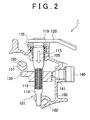
- FIGS. 2 and 3 are side sectional views of the portion shown in FIG 1 , which illustrate a manufacturing method of the manual transmission shown in FIG 1 .
- the shift outer lever shaft 110 is inserted into the through-hole 105 in the direction indicated by the arrow 115.
- the shift outer lever shaft 110 is inserted until the shift outer lever 120 contacts the spacer 170.
- the shift inner lever 130 engages with the splines 112 of the shift outer lever shaft 110.
- the shift select shaft 150 is mounted in the transmission case 100.
- the shift select shaft 150 is mounted in the transmission case 100 in a position between the shift inner lever 130 and the transmission case 100 in the axial direction of the shift outer lever shaft 110.
- the shift inner lever 130 is not engaged with the groove portion 151 of the shift select shaft 150.
- the shift outer lever shaft 110 is moved in the direction indicated by the arrow 116. Accordingly, the shift inner lever 130 also moves in the direction indicated by the arrow 116. As a result, the tip end portion of the shift inner lever 130 engages with the groove portion 151 of the shift select shaft 150, thereby completing assembly of the manual transmission 1 as shown in FIG 1 .
- FIG 4 is a plan view of an E-ring used in this example embodiment of the invention.
- the annular groove 119 comes out above the spacer 170, at which time the E-ring 160 is fitted into the annular groove 119, thereby fixing the position of the shift outer lever shaft 110 in the axial direction.
- the shift function and the select function are carried out by independent component parts and are combined when these parts are assembled.
- the transmission case 100 need only be provided with a hole, and assembly is possible by inserting the shift outer lever shaft 110 into this hole, thereby obviating the need to divide the transmission case 100.
- the shift outer lever shaft 110 is structured so as to be able to be inserted to a point where the shift inner lever 130 will not engage with the shift select shaft 150. More specifically, the shift outer lever 120 and the transmission case 100, and the shift outer lever shaft 110 and the transmission case 100 are designed so that there is sufficient room to enable the shift outer lever shaft 110 to be inserted beyond the position where the shift inner lever 130 engages with the shift select shaft 150 to a position where the two are not engaged with each other.
- the shift outer lever shaft 110 and the shift inner lever 130 may be temporarily mounted in the transmission case 100 before the shift select shaft 150 is mounted in order to place the shift inner lever 130 in a position in the transmission case 100 where it will not engage with the shift select shaft 150 before the shift select shaft 150 is inserted into the transmission case 100.
- a cover and a fastening member which are separately required with a structure in which the shift outer lever shaft 110 and the shift inner lever 130 are mounted after the shift select shaft 150 has been mounted, are able to be omitted.
- the input portion 101 also includes the shift outer lever shaft 110 that engages with the shift inner lever 130.
- the manufacturing method of the transmission includes the steps of i) inserting the shift outer lever shaft 110 into the transmission case 100, ii) engaging the shift inner lever 130 which is not engaged with the shift select shaft 150 inside the transmission case 100, with the shift outer lever shaft 110 and moving the shift inner lever 130 to a position where it will not engage with the shift select shaft 150, iii) mounting the shift select shaft 150 in the transmission case 100 after the shift inner lever 130 has been moved, iv) and engaging the shift inner lever 130 with the shift select shaft 150 by moving the shift outer lever shaft 110 toward the outside of the transmission case 100.
- the manufacturing method may also include the step of positioning the shift outer lever shaft 110 with respect to the transmission case 100 after the shift inner lever 130 is engaged with the shift select shaft 150.
Landscapes
- Engineering & Computer Science (AREA)
- General Engineering & Computer Science (AREA)
- Mechanical Engineering (AREA)
- Gear-Shifting Mechanisms (AREA)
Applications Claiming Priority (1)
| Application Number | Priority Date | Filing Date | Title |
|---|---|---|---|
| JP2008150858A JP4821806B2 (ja) | 2008-06-09 | 2008-06-09 | 変速機およびその製造方法 |
Publications (3)
| Publication Number | Publication Date |
|---|---|
| EP2133601A2 true EP2133601A2 (de) | 2009-12-16 |
| EP2133601A3 EP2133601A3 (de) | 2012-01-25 |
| EP2133601B1 EP2133601B1 (de) | 2015-07-22 |
Family
ID=40953180
Family Applications (1)
| Application Number | Title | Priority Date | Filing Date |
|---|---|---|---|
| EP09251487.6A Ceased EP2133601B1 (de) | 2008-06-09 | 2009-06-04 | Getriebe und entsprechendes Herstellungsverfahren |
Country Status (2)
| Country | Link |
|---|---|
| EP (1) | EP2133601B1 (de) |
| JP (1) | JP4821806B2 (de) |
Families Citing this family (1)
| Publication number | Priority date | Publication date | Assignee | Title |
|---|---|---|---|---|
| KR101447375B1 (ko) * | 2013-07-02 | 2014-11-04 | 현대다이모스(주) | 차량용 변속기의 시프트 레버 |
Citations (2)
| Publication number | Priority date | Publication date | Assignee | Title |
|---|---|---|---|---|
| JPH09280368A (ja) | 1996-04-11 | 1997-10-28 | Fuji Univance:Kk | 変速機のストライキングレバーの組立方法および変速機 |
| JP2007132358A (ja) | 2005-11-08 | 2007-05-31 | Toyota Motor Corp | 手動変速機の操作機構 |
Family Cites Families (5)
| Publication number | Priority date | Publication date | Assignee | Title |
|---|---|---|---|---|
| JPS5232645Y2 (de) * | 1973-10-29 | 1977-07-26 | ||
| JPH03108958U (de) * | 1990-02-23 | 1991-11-08 | ||
| US5101680A (en) * | 1991-07-19 | 1992-04-07 | General Motors Corporation | Inhibitor for a manual transmission shift control |
| JP3475711B2 (ja) * | 1997-04-24 | 2003-12-08 | 三菱自動車エンジニアリング株式会社 | 手動変速機の操作装置 |
| JP4401723B2 (ja) * | 2003-09-25 | 2010-01-20 | 本田技研工業株式会社 | マニュアルトランスミッションの変速操作機構 |
-
2008
- 2008-06-09 JP JP2008150858A patent/JP4821806B2/ja not_active Expired - Fee Related
-
2009
- 2009-06-04 EP EP09251487.6A patent/EP2133601B1/de not_active Ceased
Patent Citations (2)
| Publication number | Priority date | Publication date | Assignee | Title |
|---|---|---|---|---|
| JPH09280368A (ja) | 1996-04-11 | 1997-10-28 | Fuji Univance:Kk | 変速機のストライキングレバーの組立方法および変速機 |
| JP2007132358A (ja) | 2005-11-08 | 2007-05-31 | Toyota Motor Corp | 手動変速機の操作機構 |
Also Published As
| Publication number | Publication date |
|---|---|
| JP4821806B2 (ja) | 2011-11-24 |
| JP2009293781A (ja) | 2009-12-17 |
| EP2133601B1 (de) | 2015-07-22 |
| EP2133601A3 (de) | 2012-01-25 |
Similar Documents
| Publication | Publication Date | Title |
|---|---|---|
| US8146455B2 (en) | Reverse clip cap terminal connector | |
| EP3141780B1 (de) | Gangschaltbetriebsmechanismus | |
| US9926967B2 (en) | Coupling structure for coupling two members | |
| EP1741959B1 (de) | Montagestruktur eines drehelements | |
| EP2133601B1 (de) | Getriebe und entsprechendes Herstellungsverfahren | |
| CN104126086A (zh) | 用于变速器的换挡选择装置 | |
| US7909702B2 (en) | Shaft mounting structure of constant velocity joint | |
| JP4904968B2 (ja) | 車両用手動変速機 | |
| JP4824459B2 (ja) | 機械式クラッチユニット | |
| JP2009085284A (ja) | ピン連結構造及びそれを有する変速機の操作装置 | |
| KR101519229B1 (ko) | 수동변속기 오조작 방지 장치 | |
| US20190128416A1 (en) | Shift device of transmission | |
| JP5051040B2 (ja) | ディファレンシャル装置 | |
| JP2010274702A (ja) | パーキング装置構造 | |
| KR100783539B1 (ko) | 수동 변속기의 변속 조작장치 | |
| KR102761477B1 (ko) | Sbw 액추에이터 | |
| US9074619B2 (en) | Terminal support device mounting structure | |
| JP5258587B2 (ja) | 変速機操作用倍力装置 | |
| US20190195362A1 (en) | Interlock mechanism | |
| JP5274617B2 (ja) | 自動変速機の変速操作機構及びその組立方法 | |
| KR100323416B1 (ko) | 수동 변속기의 중립 위치 설정 기구 | |
| KR20090118138A (ko) | 수동변속 차량의 후진 오조작 방지장치 | |
| JP6221080B2 (ja) | コントロールシャフトの取付構造 | |
| JP2005282721A (ja) | ベルト式無段変速機 | |
| KR20240135243A (ko) | 전자식 변속장치 |
Legal Events
| Date | Code | Title | Description |
|---|---|---|---|
| PUAI | Public reference made under article 153(3) epc to a published international application that has entered the european phase |
Free format text: ORIGINAL CODE: 0009012 |
|
| 17P | Request for examination filed |
Effective date: 20090622 |
|
| AK | Designated contracting states |
Kind code of ref document: A2 Designated state(s): AT BE BG CH CY CZ DE DK EE ES FI FR GB GR HR HU IE IS IT LI LT LU LV MC MK MT NL NO PL PT RO SE SI SK TR |
|
| REG | Reference to a national code |
Ref country code: DE Ref legal event code: R079 Ref document number: 602009032321 Country of ref document: DE Free format text: PREVIOUS MAIN CLASS: F16H0063300000 Ipc: F16H0063200000 |
|
| PUAL | Search report despatched |
Free format text: ORIGINAL CODE: 0009013 |
|
| AK | Designated contracting states |
Kind code of ref document: A3 Designated state(s): AT BE BG CH CY CZ DE DK EE ES FI FR GB GR HR HU IE IS IT LI LT LU LV MC MK MT NL NO PL PT RO SE SI SK TR |
|
| AX | Request for extension of the european patent |
Extension state: AL BA RS |
|
| RIC1 | Information provided on ipc code assigned before grant |
Ipc: F16H 63/30 20060101ALI20111219BHEP Ipc: F16H 63/20 20060101AFI20111219BHEP |
|
| 17Q | First examination report despatched |
Effective date: 20121219 |
|
| RAP1 | Party data changed (applicant data changed or rights of an application transferred) |
Owner name: TOYOTA JIDOSHA KABUSHIKI KAISHA |
|
| GRAP | Despatch of communication of intention to grant a patent |
Free format text: ORIGINAL CODE: EPIDOSNIGR1 |
|
| INTG | Intention to grant announced |
Effective date: 20150113 |
|
| GRAS | Grant fee paid |
Free format text: ORIGINAL CODE: EPIDOSNIGR3 |
|
| GRAA | (expected) grant |
Free format text: ORIGINAL CODE: 0009210 |
|
| RBV | Designated contracting states (corrected) |
Designated state(s): DE |
|
| AK | Designated contracting states |
Kind code of ref document: B1 Designated state(s): DE |
|
| REG | Reference to a national code |
Ref country code: DE Ref legal event code: R096 Ref document number: 602009032321 Country of ref document: DE |
|
| REG | Reference to a national code |
Ref country code: DE Ref legal event code: R084 Ref document number: 602009032321 Country of ref document: DE |
|
| REG | Reference to a national code |
Ref country code: DE Ref legal event code: R097 Ref document number: 602009032321 Country of ref document: DE |
|
| PLBE | No opposition filed within time limit |
Free format text: ORIGINAL CODE: 0009261 |
|
| STAA | Information on the status of an ep patent application or granted ep patent |
Free format text: STATUS: NO OPPOSITION FILED WITHIN TIME LIMIT |
|
| 26N | No opposition filed |
Effective date: 20160425 |
|
| REG | Reference to a national code |
Ref country code: DE Ref legal event code: R081 Ref document number: 602009032321 Country of ref document: DE Owner name: AISIN AI CO., LTD., NISHIO-SHI, JP Free format text: FORMER OWNER: TOYOTA JIDOSHA K.K., TOYOTA-SHI, AICHI-KEN, JP Ref country code: DE Ref legal event code: R082 Ref document number: 602009032321 Country of ref document: DE Representative=s name: TBK, DE Ref country code: DE Ref legal event code: R081 Ref document number: 602009032321 Country of ref document: DE Owner name: AISIN AI CO., LTD., NISHIO, JP Free format text: FORMER OWNER: TOYOTA JIDOSHA K.K., TOYOTA-SHI, AICHI-KEN, JP |
|
| REG | Reference to a national code |
Ref country code: DE Ref legal event code: R082 Ref document number: 602009032321 Country of ref document: DE Representative=s name: TBK, DE Ref country code: DE Ref legal event code: R081 Ref document number: 602009032321 Country of ref document: DE Owner name: AISIN AI CO., LTD., NISHIO-SHI, JP Free format text: FORMER OWNER: AISIN AI CO., LTD., NISHIO, AICHI, JP |
|
| PGFP | Annual fee paid to national office [announced via postgrant information from national office to epo] |
Ref country code: DE Payment date: 20190521 Year of fee payment: 11 |
|
| REG | Reference to a national code |
Ref country code: DE Ref legal event code: R119 Ref document number: 602009032321 Country of ref document: DE |
|
| PG25 | Lapsed in a contracting state [announced via postgrant information from national office to epo] |
Ref country code: DE Free format text: LAPSE BECAUSE OF NON-PAYMENT OF DUE FEES Effective date: 20210101 |