EP2129491B1 - Article abrasif avec revêtement surdimensionné et procédé de fabrication - Google Patents
Article abrasif avec revêtement surdimensionné et procédé de fabrication Download PDFInfo
- Publication number
- EP2129491B1 EP2129491B1 EP08714158A EP08714158A EP2129491B1 EP 2129491 B1 EP2129491 B1 EP 2129491B1 EP 08714158 A EP08714158 A EP 08714158A EP 08714158 A EP08714158 A EP 08714158A EP 2129491 B1 EP2129491 B1 EP 2129491B1
- Authority
- EP
- European Patent Office
- Prior art keywords
- abrasive
- coating
- backing
- laser
- abrasive article
- Prior art date
- Legal status (The legal status is an assumption and is not a legal conclusion. Google has not performed a legal analysis and makes no representation as to the accuracy of the status listed.)
- Not-in-force
Links
- 238000000576 coating method Methods 0.000 title claims abstract description 102
- 239000011248 coating agent Substances 0.000 title claims abstract description 94
- 238000004519 manufacturing process Methods 0.000 title claims description 6
- 238000000034 method Methods 0.000 claims abstract description 32
- 239000002245 particle Substances 0.000 claims description 47
- 239000002131 composite material Substances 0.000 claims description 13
- 229910052751 metal Inorganic materials 0.000 claims description 4
- 239000002184 metal Substances 0.000 claims description 4
- 235000014113 dietary fatty acids Nutrition 0.000 claims description 2
- 239000000194 fatty acid Substances 0.000 claims description 2
- 229930195729 fatty acid Natural products 0.000 claims description 2
- 150000004665 fatty acids Chemical class 0.000 claims description 2
- 150000003839 salts Chemical class 0.000 claims description 2
- QIQXTHQIDYTFRH-UHFFFAOYSA-N octadecanoic acid Chemical compound CCCCCCCCCCCCCCCCCC(O)=O QIQXTHQIDYTFRH-UHFFFAOYSA-N 0.000 claims 1
- 238000006243 chemical reaction Methods 0.000 abstract description 9
- 239000000428 dust Substances 0.000 abstract description 4
- 230000007246 mechanism Effects 0.000 abstract description 2
- CURLTUGMZLYLDI-UHFFFAOYSA-N Carbon dioxide Chemical compound O=C=O CURLTUGMZLYLDI-UHFFFAOYSA-N 0.000 description 22
- 229910002092 carbon dioxide Inorganic materials 0.000 description 18
- 239000010410 layer Substances 0.000 description 18
- 239000000463 material Substances 0.000 description 18
- 239000000853 adhesive Substances 0.000 description 15
- 230000001070 adhesive effect Effects 0.000 description 15
- 239000011230 binding agent Substances 0.000 description 14
- 239000002243 precursor Substances 0.000 description 13
- 239000007789 gas Substances 0.000 description 10
- 238000005520 cutting process Methods 0.000 description 9
- 229920000647 polyepoxide Polymers 0.000 description 9
- 239000011159 matrix material Substances 0.000 description 8
- -1 potassium tetrafluoroborate Chemical compound 0.000 description 8
- 239000002002 slurry Substances 0.000 description 8
- NIXOWILDQLNWCW-UHFFFAOYSA-M acrylate group Chemical class C(C=C)(=O)[O-] NIXOWILDQLNWCW-UHFFFAOYSA-M 0.000 description 7
- IJGRMHOSHXDMSA-UHFFFAOYSA-N Atomic nitrogen Chemical compound N#N IJGRMHOSHXDMSA-UHFFFAOYSA-N 0.000 description 6
- WSFSSNUMVMOOMR-UHFFFAOYSA-N Formaldehyde Chemical compound O=C WSFSSNUMVMOOMR-UHFFFAOYSA-N 0.000 description 6
- 239000003822 epoxy resin Substances 0.000 description 6
- LNEPOXFFQSENCJ-UHFFFAOYSA-N haloperidol Chemical compound C1CC(O)(C=2C=CC(Cl)=CC=2)CCN1CCCC(=O)C1=CC=C(F)C=C1 LNEPOXFFQSENCJ-UHFFFAOYSA-N 0.000 description 6
- 229920005989 resin Polymers 0.000 description 6
- 239000011347 resin Substances 0.000 description 6
- TWNQGVIAIRXVLR-UHFFFAOYSA-N oxo(oxoalumanyloxy)alumane Chemical compound O=[Al]O[Al]=O TWNQGVIAIRXVLR-UHFFFAOYSA-N 0.000 description 5
- 229920001568 phenolic resin Polymers 0.000 description 5
- 150000003254 radicals Chemical class 0.000 description 5
- VYPSYNLAJGMNEJ-UHFFFAOYSA-N silicon dioxide Inorganic materials O=[Si]=O VYPSYNLAJGMNEJ-UHFFFAOYSA-N 0.000 description 5
- NIXOWILDQLNWCW-UHFFFAOYSA-N 2-Propenoic acid Natural products OC(=O)C=C NIXOWILDQLNWCW-UHFFFAOYSA-N 0.000 description 4
- 239000001569 carbon dioxide Substances 0.000 description 4
- 229920003986 novolac Polymers 0.000 description 4
- 239000005011 phenolic resin Substances 0.000 description 4
- 238000012360 testing method Methods 0.000 description 4
- 238000012546 transfer Methods 0.000 description 4
- XOOUIPVCVHRTMJ-UHFFFAOYSA-L zinc stearate Chemical compound [Zn+2].CCCCCCCCCCCCCCCCCC([O-])=O.CCCCCCCCCCCCCCCCCC([O-])=O XOOUIPVCVHRTMJ-UHFFFAOYSA-L 0.000 description 4
- ISWSIDIOOBJBQZ-UHFFFAOYSA-N Phenol Chemical compound OC1=CC=CC=C1 ISWSIDIOOBJBQZ-UHFFFAOYSA-N 0.000 description 3
- 230000008901 benefit Effects 0.000 description 3
- 125000002915 carbonyl group Chemical group [*:2]C([*:1])=O 0.000 description 3
- 239000003795 chemical substances by application Substances 0.000 description 3
- 150000001875 compounds Chemical class 0.000 description 3
- 230000007547 defect Effects 0.000 description 3
- 125000004386 diacrylate group Chemical group 0.000 description 3
- 239000003085 diluting agent Substances 0.000 description 3
- 230000000694 effects Effects 0.000 description 3
- 238000010894 electron beam technology Methods 0.000 description 3
- 150000002148 esters Chemical class 0.000 description 3
- 238000000227 grinding Methods 0.000 description 3
- 239000003999 initiator Substances 0.000 description 3
- 239000012948 isocyanate Chemical class 0.000 description 3
- 150000002513 isocyanates Chemical class 0.000 description 3
- ZFSLODLOARCGLH-UHFFFAOYSA-N isocyanuric acid Chemical class OC1=NC(O)=NC(O)=N1 ZFSLODLOARCGLH-UHFFFAOYSA-N 0.000 description 3
- 239000000203 mixture Substances 0.000 description 3
- 229910052757 nitrogen Inorganic materials 0.000 description 3
- 230000008569 process Effects 0.000 description 3
- 239000000047 product Substances 0.000 description 3
- 229920001169 thermoplastic Polymers 0.000 description 3
- 239000004416 thermosoftening plastic Substances 0.000 description 3
- 238000011282 treatment Methods 0.000 description 3
- MYWOJODOMFBVCB-UHFFFAOYSA-N 1,2,6-trimethylphenanthrene Chemical compound CC1=CC=C2C3=CC(C)=CC=C3C=CC2=C1C MYWOJODOMFBVCB-UHFFFAOYSA-N 0.000 description 2
- MYRTYDVEIRVNKP-UHFFFAOYSA-N 1,2-Divinylbenzene Chemical compound C=CC1=CC=CC=C1C=C MYRTYDVEIRVNKP-UHFFFAOYSA-N 0.000 description 2
- INQDDHNZXOAFFD-UHFFFAOYSA-N 2-[2-(2-prop-2-enoyloxyethoxy)ethoxy]ethyl prop-2-enoate Chemical compound C=CC(=O)OCCOCCOCCOC(=O)C=C INQDDHNZXOAFFD-UHFFFAOYSA-N 0.000 description 2
- KUDUQBURMYMBIJ-UHFFFAOYSA-N 2-prop-2-enoyloxyethyl prop-2-enoate Chemical compound C=CC(=O)OCCOC(=O)C=C KUDUQBURMYMBIJ-UHFFFAOYSA-N 0.000 description 2
- HRPVXLWXLXDGHG-UHFFFAOYSA-N Acrylamide Chemical compound NC(=O)C=C HRPVXLWXLXDGHG-UHFFFAOYSA-N 0.000 description 2
- VTYYLEPIZMXCLO-UHFFFAOYSA-L Calcium carbonate Chemical compound [Ca+2].[O-]C([O-])=O VTYYLEPIZMXCLO-UHFFFAOYSA-L 0.000 description 2
- RTZKZFJDLAIYFH-UHFFFAOYSA-N Diethyl ether Chemical compound CCOCC RTZKZFJDLAIYFH-UHFFFAOYSA-N 0.000 description 2
- 239000004593 Epoxy Substances 0.000 description 2
- UQSXHKLRYXJYBZ-UHFFFAOYSA-N Iron oxide Chemical compound [Fe]=O UQSXHKLRYXJYBZ-UHFFFAOYSA-N 0.000 description 2
- PPBRXRYQALVLMV-UHFFFAOYSA-N Styrene Chemical compound C=CC1=CC=CC=C1 PPBRXRYQALVLMV-UHFFFAOYSA-N 0.000 description 2
- MCMNRKCIXSYSNV-UHFFFAOYSA-N Zirconium dioxide Chemical compound O=[Zr]=O MCMNRKCIXSYSNV-UHFFFAOYSA-N 0.000 description 2
- 125000001931 aliphatic group Chemical group 0.000 description 2
- 150000001408 amides Chemical class 0.000 description 2
- 229920003180 amino resin Chemical class 0.000 description 2
- QVGXLLKOCUKJST-UHFFFAOYSA-N atomic oxygen Chemical compound [O] QVGXLLKOCUKJST-UHFFFAOYSA-N 0.000 description 2
- 125000000751 azo group Chemical group [*]N=N[*] 0.000 description 2
- 230000009286 beneficial effect Effects 0.000 description 2
- 239000012965 benzophenone Substances 0.000 description 2
- 150000008366 benzophenones Chemical class 0.000 description 2
- 150000001735 carboxylic acids Chemical class 0.000 description 2
- 230000000052 comparative effect Effects 0.000 description 2
- 230000007423 decrease Effects 0.000 description 2
- 230000003247 decreasing effect Effects 0.000 description 2
- 229910003460 diamond Inorganic materials 0.000 description 2
- 239000010432 diamond Substances 0.000 description 2
- GYZLOYUZLJXAJU-UHFFFAOYSA-N diglycidyl ether Chemical compound C1OC1COCC1CO1 GYZLOYUZLJXAJU-UHFFFAOYSA-N 0.000 description 2
- 238000005516 engineering process Methods 0.000 description 2
- 125000003700 epoxy group Chemical group 0.000 description 2
- 239000004744 fabric Substances 0.000 description 2
- 239000000835 fiber Substances 0.000 description 2
- 239000011521 glass Substances 0.000 description 2
- 239000012943 hotmelt Substances 0.000 description 2
- 239000001257 hydrogen Substances 0.000 description 2
- 229910052739 hydrogen Inorganic materials 0.000 description 2
- 230000000977 initiatory effect Effects 0.000 description 2
- 238000003475 lamination Methods 0.000 description 2
- 238000003698 laser cutting Methods 0.000 description 2
- 229910052760 oxygen Inorganic materials 0.000 description 2
- 239000001301 oxygen Substances 0.000 description 2
- 229920000728 polyester Polymers 0.000 description 2
- 238000006116 polymerization reaction Methods 0.000 description 2
- 238000012545 processing Methods 0.000 description 2
- 150000004053 quinones Chemical class 0.000 description 2
- 230000005855 radiation Effects 0.000 description 2
- 239000003870 refractory metal Substances 0.000 description 2
- 229920003987 resole Polymers 0.000 description 2
- 230000000717 retained effect Effects 0.000 description 2
- 238000006748 scratching Methods 0.000 description 2
- 230000002393 scratching effect Effects 0.000 description 2
- HBMJWWWQQXIZIP-UHFFFAOYSA-N silicon carbide Chemical compound [Si+]#[C-] HBMJWWWQQXIZIP-UHFFFAOYSA-N 0.000 description 2
- 229910010271 silicon carbide Inorganic materials 0.000 description 2
- 239000000377 silicon dioxide Substances 0.000 description 2
- 239000007787 solid Substances 0.000 description 2
- 238000001228 spectrum Methods 0.000 description 2
- 239000000126 substance Substances 0.000 description 2
- LDHQCZJRKDOVOX-UHFFFAOYSA-N trans-crotonic acid Natural products CC=CC(O)=O LDHQCZJRKDOVOX-UHFFFAOYSA-N 0.000 description 2
- 150000003673 urethanes Chemical class 0.000 description 2
- 238000009423 ventilation Methods 0.000 description 2
- BPXVHIRIPLPOPT-UHFFFAOYSA-N 1,3,5-tris(2-hydroxyethyl)-1,3,5-triazinane-2,4,6-trione Chemical compound OCCN1C(=O)N(CCO)C(=O)N(CCO)C1=O BPXVHIRIPLPOPT-UHFFFAOYSA-N 0.000 description 1
- PBGPBHYPCGDFEZ-UHFFFAOYSA-N 1-ethenylpiperidin-2-one Chemical compound C=CN1CCCCC1=O PBGPBHYPCGDFEZ-UHFFFAOYSA-N 0.000 description 1
- VOBUAPTXJKMNCT-UHFFFAOYSA-N 1-prop-2-enoyloxyhexyl prop-2-enoate Chemical compound CCCCCC(OC(=O)C=C)OC(=O)C=C VOBUAPTXJKMNCT-UHFFFAOYSA-N 0.000 description 1
- PUGOMSLRUSTQGV-UHFFFAOYSA-N 2,3-di(prop-2-enoyloxy)propyl prop-2-enoate Chemical compound C=CC(=O)OCC(OC(=O)C=C)COC(=O)C=C PUGOMSLRUSTQGV-UHFFFAOYSA-N 0.000 description 1
- SMZOUWXMTYCWNB-UHFFFAOYSA-N 2-(2-methoxy-5-methylphenyl)ethanamine Chemical compound COC1=CC=C(C)C=C1CCN SMZOUWXMTYCWNB-UHFFFAOYSA-N 0.000 description 1
- JAHNSTQSQJOJLO-UHFFFAOYSA-N 2-(3-fluorophenyl)-1h-imidazole Chemical compound FC1=CC=CC(C=2NC=CN=2)=C1 JAHNSTQSQJOJLO-UHFFFAOYSA-N 0.000 description 1
- YIJYFLXQHDOQGW-UHFFFAOYSA-N 2-[2,4,6-trioxo-3,5-bis(2-prop-2-enoyloxyethyl)-1,3,5-triazinan-1-yl]ethyl prop-2-enoate Chemical compound C=CC(=O)OCCN1C(=O)N(CCOC(=O)C=C)C(=O)N(CCOC(=O)C=C)C1=O YIJYFLXQHDOQGW-UHFFFAOYSA-N 0.000 description 1
- 229910052580 B4C Inorganic materials 0.000 description 1
- 229910052582 BN Inorganic materials 0.000 description 1
- 239000004342 Benzoyl peroxide Substances 0.000 description 1
- OMPJBNCRMGITSC-UHFFFAOYSA-N Benzoylperoxide Chemical compound C=1C=CC=CC=1C(=O)OOC(=O)C1=CC=CC=C1 OMPJBNCRMGITSC-UHFFFAOYSA-N 0.000 description 1
- 229930185605 Bisphenol Natural products 0.000 description 1
- PZNSFCLAULLKQX-UHFFFAOYSA-N Boron nitride Chemical compound N#B PZNSFCLAULLKQX-UHFFFAOYSA-N 0.000 description 1
- OKTJSMMVPCPJKN-UHFFFAOYSA-N Carbon Chemical compound [C] OKTJSMMVPCPJKN-UHFFFAOYSA-N 0.000 description 1
- UGFAIRIUMAVXCW-UHFFFAOYSA-N Carbon monoxide Chemical compound [O+]#[C-] UGFAIRIUMAVXCW-UHFFFAOYSA-N 0.000 description 1
- YZCKVEUIGOORGS-OUBTZVSYSA-N Deuterium Chemical compound [2H] YZCKVEUIGOORGS-OUBTZVSYSA-N 0.000 description 1
- 239000004641 Diallyl-phthalate Substances 0.000 description 1
- VGGSQFUCUMXWEO-UHFFFAOYSA-N Ethene Chemical compound C=C VGGSQFUCUMXWEO-UHFFFAOYSA-N 0.000 description 1
- JOYRKODLDBILNP-UHFFFAOYSA-N Ethyl urethane Chemical compound CCOC(N)=O JOYRKODLDBILNP-UHFFFAOYSA-N 0.000 description 1
- 239000005977 Ethylene Substances 0.000 description 1
- IAYPIBMASNFSPL-UHFFFAOYSA-N Ethylene oxide Chemical compound C1CO1 IAYPIBMASNFSPL-UHFFFAOYSA-N 0.000 description 1
- KRHYYFGTRYWZRS-UHFFFAOYSA-N Fluorane Chemical compound F KRHYYFGTRYWZRS-UHFFFAOYSA-N 0.000 description 1
- UFHFLCQGNIYNRP-UHFFFAOYSA-N Hydrogen Chemical compound [H][H] UFHFLCQGNIYNRP-UHFFFAOYSA-N 0.000 description 1
- WOBHKFSMXKNTIM-UHFFFAOYSA-N Hydroxyethyl methacrylate Chemical compound CC(=C)C(=O)OCCO WOBHKFSMXKNTIM-UHFFFAOYSA-N 0.000 description 1
- 235000019738 Limestone Nutrition 0.000 description 1
- 229920000877 Melamine resin Polymers 0.000 description 1
- CERQOIWHTDAKMF-UHFFFAOYSA-M Methacrylate Chemical compound CC(=C)C([O-])=O CERQOIWHTDAKMF-UHFFFAOYSA-M 0.000 description 1
- CERQOIWHTDAKMF-UHFFFAOYSA-N Methacrylic acid Chemical compound CC(=C)C(O)=O CERQOIWHTDAKMF-UHFFFAOYSA-N 0.000 description 1
- VVQNEPGJFQJSBK-UHFFFAOYSA-N Methyl methacrylate Chemical compound COC(=O)C(C)=C VVQNEPGJFQJSBK-UHFFFAOYSA-N 0.000 description 1
- CNCOEDDPFOAUMB-UHFFFAOYSA-N N-Methylolacrylamide Chemical compound OCNC(=O)C=C CNCOEDDPFOAUMB-UHFFFAOYSA-N 0.000 description 1
- WHNWPMSKXPGLAX-UHFFFAOYSA-N N-Vinyl-2-pyrrolidone Chemical compound C=CN1CCCC1=O WHNWPMSKXPGLAX-UHFFFAOYSA-N 0.000 description 1
- 229910017502 Nd:YVO4 Inorganic materials 0.000 description 1
- 239000004820 Pressure-sensitive adhesive Substances 0.000 description 1
- OFOBLEOULBTSOW-UHFFFAOYSA-N Propanedioic acid Natural products OC(=O)CC(O)=O OFOBLEOULBTSOW-UHFFFAOYSA-N 0.000 description 1
- 244000028419 Styrax benzoin Species 0.000 description 1
- 235000000126 Styrax benzoin Nutrition 0.000 description 1
- 235000008411 Sumatra benzointree Nutrition 0.000 description 1
- DAKWPKUUDNSNPN-UHFFFAOYSA-N Trimethylolpropane triacrylate Chemical compound C=CC(=O)OCC(CC)(COC(=O)C=C)COC(=O)C=C DAKWPKUUDNSNPN-UHFFFAOYSA-N 0.000 description 1
- 229920001807 Urea-formaldehyde Polymers 0.000 description 1
- QYKIQEUNHZKYBP-UHFFFAOYSA-N Vinyl ether Chemical class C=COC=C QYKIQEUNHZKYBP-UHFFFAOYSA-N 0.000 description 1
- HVVWZTWDBSEWIH-UHFFFAOYSA-N [2-(hydroxymethyl)-3-prop-2-enoyloxy-2-(prop-2-enoyloxymethyl)propyl] prop-2-enoate Chemical compound C=CC(=O)OCC(CO)(COC(=O)C=C)COC(=O)C=C HVVWZTWDBSEWIH-UHFFFAOYSA-N 0.000 description 1
- APZPSKFMSWZPKL-UHFFFAOYSA-N [3-hydroxy-2,2-bis(hydroxymethyl)propyl] 2-methylprop-2-enoate Chemical compound CC(=C)C(=O)OCC(CO)(CO)CO APZPSKFMSWZPKL-UHFFFAOYSA-N 0.000 description 1
- VZPPHXVFMVZRTE-UHFFFAOYSA-N [Kr]F Chemical compound [Kr]F VZPPHXVFMVZRTE-UHFFFAOYSA-N 0.000 description 1
- YKTSYUJCYHOUJP-UHFFFAOYSA-N [O--].[Al+3].[Al+3].[O-][Si]([O-])([O-])[O-] Chemical compound [O--].[Al+3].[Al+3].[O-][Si]([O-])([O-])[O-] YKTSYUJCYHOUJP-UHFFFAOYSA-N 0.000 description 1
- 239000003082 abrasive agent Substances 0.000 description 1
- 238000010521 absorption reaction Methods 0.000 description 1
- 238000009825 accumulation Methods 0.000 description 1
- 150000008062 acetophenones Chemical class 0.000 description 1
- 150000001252 acrylic acid derivatives Chemical class 0.000 description 1
- 230000009471 action Effects 0.000 description 1
- 239000002390 adhesive tape Substances 0.000 description 1
- 230000002411 adverse Effects 0.000 description 1
- PNEYBMLMFCGWSK-UHFFFAOYSA-N aluminium oxide Inorganic materials [O-2].[O-2].[O-2].[Al+3].[Al+3] PNEYBMLMFCGWSK-UHFFFAOYSA-N 0.000 description 1
- 230000003321 amplification Effects 0.000 description 1
- 125000004429 atom Chemical group 0.000 description 1
- 239000011324 bead Substances 0.000 description 1
- WURBFLDFSFBTLW-UHFFFAOYSA-N benzil Chemical compound C=1C=CC=CC=1C(=O)C(=O)C1=CC=CC=C1 WURBFLDFSFBTLW-UHFFFAOYSA-N 0.000 description 1
- 229960002130 benzoin Drugs 0.000 description 1
- 235000019400 benzoyl peroxide Nutrition 0.000 description 1
- 230000015572 biosynthetic process Effects 0.000 description 1
- QUDWYFHPNIMBFC-UHFFFAOYSA-N bis(prop-2-enyl) benzene-1,2-dicarboxylate Chemical compound C=CCOC(=O)C1=CC=CC=C1C(=O)OCC=C QUDWYFHPNIMBFC-UHFFFAOYSA-N 0.000 description 1
- FPODCVUTIPDRTE-UHFFFAOYSA-N bis(prop-2-enyl) hexanedioate Chemical compound C=CCOC(=O)CCCCC(=O)OCC=C FPODCVUTIPDRTE-UHFFFAOYSA-N 0.000 description 1
- IISBACLAFKSPIT-UHFFFAOYSA-N bisphenol A Chemical compound C=1C=C(O)C=CC=1C(C)(C)C1=CC=C(O)C=C1 IISBACLAFKSPIT-UHFFFAOYSA-N 0.000 description 1
- 239000004841 bisphenol A epoxy resin Substances 0.000 description 1
- INAHAJYZKVIDIZ-UHFFFAOYSA-N boron carbide Chemical compound B12B3B4C32B41 INAHAJYZKVIDIZ-UHFFFAOYSA-N 0.000 description 1
- 229910000019 calcium carbonate Inorganic materials 0.000 description 1
- CJZGTCYPCWQAJB-UHFFFAOYSA-L calcium stearate Chemical compound [Ca+2].CCCCCCCCCCCCCCCCCC([O-])=O.CCCCCCCCCCCCCCCCCC([O-])=O CJZGTCYPCWQAJB-UHFFFAOYSA-L 0.000 description 1
- 235000013539 calcium stearate Nutrition 0.000 description 1
- 239000008116 calcium stearate Substances 0.000 description 1
- 229910052799 carbon Inorganic materials 0.000 description 1
- 229910002091 carbon monoxide Inorganic materials 0.000 description 1
- 229940105305 carbon monoxide Drugs 0.000 description 1
- 230000015556 catabolic process Effects 0.000 description 1
- 239000000919 ceramic Substances 0.000 description 1
- CETPSERCERDGAM-UHFFFAOYSA-N ceric oxide Chemical compound O=[Ce]=O CETPSERCERDGAM-UHFFFAOYSA-N 0.000 description 1
- 229910000422 cerium(IV) oxide Inorganic materials 0.000 description 1
- 238000004140 cleaning Methods 0.000 description 1
- 230000001427 coherent effect Effects 0.000 description 1
- 238000002485 combustion reaction Methods 0.000 description 1
- 238000007796 conventional method Methods 0.000 description 1
- VPYURTKRLAYHEQ-UHFFFAOYSA-N copper neon Chemical compound [Ne].[Cu] VPYURTKRLAYHEQ-UHFFFAOYSA-N 0.000 description 1
- 239000007822 coupling agent Substances 0.000 description 1
- LDHQCZJRKDOVOX-NSCUHMNNSA-N crotonic acid Chemical compound C\C=C\C(O)=O LDHQCZJRKDOVOX-NSCUHMNNSA-N 0.000 description 1
- 238000006731 degradation reaction Methods 0.000 description 1
- 230000001419 dependent effect Effects 0.000 description 1
- 238000000151 deposition Methods 0.000 description 1
- 238000013461 design Methods 0.000 description 1
- ISAOCJYIOMOJEB-UHFFFAOYSA-N desyl alcohol Natural products C=1C=CC=CC=1C(O)C(=O)C1=CC=CC=C1 ISAOCJYIOMOJEB-UHFFFAOYSA-N 0.000 description 1
- 230000001627 detrimental effect Effects 0.000 description 1
- 229910052805 deuterium Inorganic materials 0.000 description 1
- KRHYYFGTRYWZRS-DYCDLGHISA-N deuterium fluoride Chemical compound [2H]F KRHYYFGTRYWZRS-DYCDLGHISA-N 0.000 description 1
- QDOXWKRWXJOMAK-UHFFFAOYSA-N dichromium trioxide Chemical compound O=[Cr]O[Cr]=O QDOXWKRWXJOMAK-UHFFFAOYSA-N 0.000 description 1
- 230000005684 electric field Effects 0.000 description 1
- 230000005670 electromagnetic radiation Effects 0.000 description 1
- 230000005686 electrostatic field Effects 0.000 description 1
- SUPCQIBBMFXVTL-UHFFFAOYSA-N ethyl 2-methylprop-2-enoate Chemical compound CCOC(=O)C(C)=C SUPCQIBBMFXVTL-UHFFFAOYSA-N 0.000 description 1
- 230000005284 excitation Effects 0.000 description 1
- 239000012467 final product Substances 0.000 description 1
- SLGWESQGEUXWJQ-UHFFFAOYSA-N formaldehyde;phenol Chemical compound O=C.OC1=CC=CC=C1 SLGWESQGEUXWJQ-UHFFFAOYSA-N 0.000 description 1
- 239000002223 garnet Substances 0.000 description 1
- 235000019382 gum benzoic Nutrition 0.000 description 1
- 239000010440 gypsum Substances 0.000 description 1
- 229910052602 gypsum Inorganic materials 0.000 description 1
- 229910052736 halogen Inorganic materials 0.000 description 1
- 150000002367 halogens Chemical class 0.000 description 1
- 239000001307 helium Substances 0.000 description 1
- 229910052734 helium Inorganic materials 0.000 description 1
- SWQJXJOGLNCZEY-UHFFFAOYSA-N helium atom Chemical compound [He] SWQJXJOGLNCZEY-UHFFFAOYSA-N 0.000 description 1
- FPQDUGZBUIHCCW-UHFFFAOYSA-N helium silver Chemical compound [He].[Ag] FPQDUGZBUIHCCW-UHFFFAOYSA-N 0.000 description 1
- 150000002431 hydrogen Chemical class 0.000 description 1
- 229910000040 hydrogen fluoride Inorganic materials 0.000 description 1
- 229910052500 inorganic mineral Inorganic materials 0.000 description 1
- LDHQCZJRKDOVOX-IHWYPQMZSA-N isocrotonic acid Chemical compound C\C=C/C(O)=O LDHQCZJRKDOVOX-IHWYPQMZSA-N 0.000 description 1
- 239000006028 limestone Substances 0.000 description 1
- VZCYOOQTPOCHFL-UPHRSURJSA-N maleic acid Chemical compound OC(=O)\C=C/C(O)=O VZCYOOQTPOCHFL-UPHRSURJSA-N 0.000 description 1
- 239000011976 maleic acid Substances 0.000 description 1
- 239000004579 marble Substances 0.000 description 1
- 150000002734 metacrylic acid derivatives Chemical class 0.000 description 1
- 150000001247 metal acetylides Chemical class 0.000 description 1
- 229910021645 metal ion Inorganic materials 0.000 description 1
- 229910044991 metal oxide Inorganic materials 0.000 description 1
- 150000004706 metal oxides Chemical class 0.000 description 1
- FQPSGWSUVKBHSU-UHFFFAOYSA-N methacrylamide Chemical compound CC(=C)C(N)=O FQPSGWSUVKBHSU-UHFFFAOYSA-N 0.000 description 1
- LVHBHZANLOWSRM-UHFFFAOYSA-N methylenebutanedioic acid Natural products OC(=O)CC(=C)C(O)=O LVHBHZANLOWSRM-UHFFFAOYSA-N 0.000 description 1
- 239000011707 mineral Substances 0.000 description 1
- 238000012986 modification Methods 0.000 description 1
- 230000004048 modification Effects 0.000 description 1
- 229940088644 n,n-dimethylacrylamide Drugs 0.000 description 1
- YLGYACDQVQQZSW-UHFFFAOYSA-N n,n-dimethylprop-2-enamide Chemical compound CN(C)C(=O)C=C YLGYACDQVQQZSW-UHFFFAOYSA-N 0.000 description 1
- FOGSDLLFGSNQCW-UHFFFAOYSA-N n-[(prop-2-enoylamino)methoxymethyl]prop-2-enamide Chemical compound C=CC(=O)NCOCNC(=O)C=C FOGSDLLFGSNQCW-UHFFFAOYSA-N 0.000 description 1
- QKCGXXHCELUCKW-UHFFFAOYSA-N n-[4-[4-(dinaphthalen-2-ylamino)phenyl]phenyl]-n-naphthalen-2-ylnaphthalen-2-amine Chemical compound C1=CC=CC2=CC(N(C=3C=CC(=CC=3)C=3C=CC(=CC=3)N(C=3C=C4C=CC=CC4=CC=3)C=3C=C4C=CC=CC4=CC=3)C3=CC4=CC=CC=C4C=C3)=CC=C21 QKCGXXHCELUCKW-UHFFFAOYSA-N 0.000 description 1
- YPHQUSNPXDGUHL-UHFFFAOYSA-N n-methylprop-2-enamide Chemical compound CNC(=O)C=C YPHQUSNPXDGUHL-UHFFFAOYSA-N 0.000 description 1
- 150000004767 nitrides Chemical class 0.000 description 1
- 125000004433 nitrogen atom Chemical group N* 0.000 description 1
- QJGQUHMNIGDVPM-UHFFFAOYSA-N nitrogen group Chemical group [N] QJGQUHMNIGDVPM-UHFFFAOYSA-N 0.000 description 1
- 150000002832 nitroso derivatives Chemical class 0.000 description 1
- 239000004745 nonwoven fabric Substances 0.000 description 1
- 238000003199 nucleic acid amplification method Methods 0.000 description 1
- 150000001451 organic peroxides Chemical class 0.000 description 1
- 230000010355 oscillation Effects 0.000 description 1
- 150000002978 peroxides Chemical class 0.000 description 1
- 150000002989 phenols Chemical class 0.000 description 1
- 230000000704 physical effect Effects 0.000 description 1
- 238000005498 polishing Methods 0.000 description 1
- 229920000570 polyether Polymers 0.000 description 1
- 229920000642 polymer Polymers 0.000 description 1
- 229920000098 polyolefin Polymers 0.000 description 1
- 238000009824 pressure lamination Methods 0.000 description 1
- 230000002250 progressing effect Effects 0.000 description 1
- HJWLCRVIBGQPNF-UHFFFAOYSA-N prop-2-enylbenzene Chemical compound C=CCC1=CC=CC=C1 HJWLCRVIBGQPNF-UHFFFAOYSA-N 0.000 description 1
- WVIICGIFSIBFOG-UHFFFAOYSA-N pyrylium Chemical class C1=CC=[O+]C=C1 WVIICGIFSIBFOG-UHFFFAOYSA-N 0.000 description 1
- 239000010453 quartz Substances 0.000 description 1
- 230000002787 reinforcement Effects 0.000 description 1
- 238000007142 ring opening reaction Methods 0.000 description 1
- 239000002356 single layer Substances 0.000 description 1
- 238000007581 slurry coating method Methods 0.000 description 1
- 238000007711 solidification Methods 0.000 description 1
- 230000008023 solidification Effects 0.000 description 1
- 239000002344 surface layer Substances 0.000 description 1
- VZCYOOQTPOCHFL-UHFFFAOYSA-N trans-butenedioic acid Natural products OC(=O)C=CC(O)=O VZCYOOQTPOCHFL-UHFFFAOYSA-N 0.000 description 1
- QWVYNEUUYROOSZ-UHFFFAOYSA-N trioxido(oxo)vanadium;yttrium(3+) Chemical compound [Y+3].[O-][V]([O-])([O-])=O QWVYNEUUYROOSZ-UHFFFAOYSA-N 0.000 description 1
- XSQUKJJJFZCRTK-UHFFFAOYSA-N urea group Chemical group NC(=O)N XSQUKJJJFZCRTK-UHFFFAOYSA-N 0.000 description 1
- 239000002023 wood Substances 0.000 description 1
Images


Classifications
-
- B—PERFORMING OPERATIONS; TRANSPORTING
- B24—GRINDING; POLISHING
- B24D—TOOLS FOR GRINDING, BUFFING OR SHARPENING
- B24D3/00—Physical features of abrasive bodies, or sheets, e.g. abrasive surfaces of special nature; Abrasive bodies or sheets characterised by their constituents
- B24D3/001—Physical features of abrasive bodies, or sheets, e.g. abrasive surfaces of special nature; Abrasive bodies or sheets characterised by their constituents the constituent being used as supporting member
- B24D3/002—Flexible supporting members, e.g. paper, woven, plastic materials
-
- B—PERFORMING OPERATIONS; TRANSPORTING
- B24—GRINDING; POLISHING
- B24D—TOOLS FOR GRINDING, BUFFING OR SHARPENING
- B24D11/00—Constructional features of flexible abrasive materials; Special features in the manufacture of such materials
- B24D11/02—Backings, e.g. foils, webs, mesh fabrics
-
- B—PERFORMING OPERATIONS; TRANSPORTING
- B24—GRINDING; POLISHING
- B24D—TOOLS FOR GRINDING, BUFFING OR SHARPENING
- B24D2203/00—Tool surfaces formed with a pattern
Definitions
- This disclosure relates to abrasive articles and methods of making such abrasive articles.
- abrasive articles have been used to abrade and finish workpiece surfaces for well over a hundred years. These applications have ranged from high stock removal from workpieces such as wood and metal, to fine polishing of ophthalmic lenses, fiber optics and computer read/write heads.
- abrasive articles comprise a plurality of abrasive particles bonded either together (e.g., a bonded abrasive or grinding wheel) or to a backing (e.g., a coated abrasive).
- a coated abrasive there is typically a single layer, or sometimes a plurality of layers, of abrasive particles bonded to the backing.
- the abrasive particles may be bonded to the backing with a "make" and "size” coat, or as a slurry coat.
- abrasive articles for example, discs, endless belts, sanding sponges, and the like.
- the configurations of the abrasive article will affect the intended use of the articles.
- some abrasive articles are configured to be connected to a vacuum source during use, to remove dust and swarf from the abrading surface.
- the exposed tips of the abrasive particles abrade the workpiece. New particle surfaces are continuously being exposed to extend the life of the abrasive article. After a certain time, when the abrasive article no longer has a sufficient amount of decent abrading surfaces left, the coated abrasive is essentially worn out and is typically discarded.
- coated abrasive articles have been known for over a hundred years, there are always improvements being made to the articles and to the methods of making the abrasive articles.
- the present disclosure provides an abrasive article having an abrasive coating (having a plurality of abrasive particles) bonded to a first side of a backing. A supersize coating is present over the abrasive coating and any exposed surfaces of the backing.
- This disclosure also provides methods of making an abrasive article and methods of using that article.
- the methods of making the abrasive article include using a laser to cut through the backing and the abrasive coating, providing cuts that are generally fused, e.g., having generally smooth surfaces, free of asperities, having resolidified melted regions, and that may be glossy. Fused cuts have no mechanical defects, such as crushed or broken abrasive coating components or frayed backing edges.
- the laser is used in a manner so that the side of the abrasive article free of abrasive coating is cut first by the laser; i.e., the laser energy is focused on the side of the abrasive article free of abrasive coating.
- the cuts made by the laser may be internal cuts in the abrasive article.
- a first embodiment of an abrasive article is illustrated as abrasive article 10.
- Abrasive article 10 is commonly referred to as a "coated abrasive article", having a plurality of abrasive particles bonded to a backing.
- This abrasive article 10 has a backing 12, having a first side 12a and an opposite second side 12b.
- An abrasive coating 14 is present on the first side 12a of backing 12.
- Abrasive coating 14 in this embodiment, comprises a plurality of abrasive particles 15 retained by an adhesive matrix 16.
- This adhesive matrix 16 comprises a make coat 18, into which abrasive particles 15 are at least partially embedded, and an overlying size coat 17.
- Abrasive particles 15 are typically oriented in make coat 18, for example by application of an electrostatic field to the particles as they are applied.
- This embodiment of abrasive article 10 includes a supersize coat 19, present over size coat 17.
- a supersize coat or layer if present, is a coating applied on at least a portion of the size layer, and is generally added to provide, for example, a grinding aid, and/or as an anti-loading coating.
- supersize layer 19 may prevent or reduce the accumulation of swarf (the material abraded from a workpiece) on size coat 17 or between abrasive particles 15, and/or in and around apertures 45 (discussed below in respect to FIG. 4a ), which can dramatically reduce the cutting ability and/or the resulting workpiece finish provided by abrasive article 10.
- Useful supersize layers 19 include a grinding aid (e.g., potassium tetrafluoroborate) or metal salts of fatty acids (e.g., zinc stearate or calcium stearate). Other materials may be present in supersize layer 19.
- supersize layer 19 is applied over size coat 17 after conversion (e.g., by laser) of the abrasive article.
- Application of supersize layer 19 after conversion either by non-contact processes (such as by laser conversion) or by contact processes (such as mechanical die cutting), covers newly created or fresh surfaces, including, for example, newly-exposed sidewalls of the abrasive article or aperture(s) therein.
- Application of supersize layer 19 after converting (cutting) the abrasive article covers the cut surfaces and generally increases the life and/or cut rate of the abrasive article and reduces the scratching caused by exposed surfaces.
- Abrasive article 10 is a generic example of an abrasive article having a make/size adhesive matrix. It is understood that alternate configurations of abrasive articles are possible without falling out of the scope of a make/size abrasive articles.
- a second embodiment of an abrasive article is illustrated as abrasive article 20.
- Abrasive article 20 is commonly referred to as a "coated abrasive article", having a plurality of abrasive particles bonded to a backing.
- This abrasive article 20 has a backing 22, having a first side 22a and an opposite second side 22b.
- An abrasive coating 24 is present on the first side 22a of backing 22.
- a supersize layer or coating could be present over at least a portion of abrasive coating 24; this supersize coating could be applied after converting of abrasive article 20.
- Abrasive coating 24, in this embodiment, comprises a plurality of abrasive particles 25 retained by and distributed through an adhesive matrix 26.
- Abrasive article 20 is an example of a slurry coating abrasive article.
- a third embodiment of an abrasive article is illustrated as abrasive article 30.
- Abrasive article 30 is commonly referred to as a "shaped abrasive article", having a plurality of abrasive particles bonded to a backing.
- This abrasive article 30 has a backing 32, having a first side 32a and an opposite second side 32b.
- An abrasive coating 34 is present on the first side 32a of backing 32.
- a supersize layer or coating could be present over at least a portion of abrasive coating 34; this supersize coating could be applied after converting of abrasive article 30.
- Abrasive coating 34 comprises a plurality of abrasive composites 38, which are composites of abrasive particles 35 distributed in an adhesive matrix 36.
- Abrasive composites 38 are separated by a boundary or boundaries associated with the composite shape, resulting in one abrasive composite 38 being separated to some degree from another adjacent abrasive composite 38. If the boundaries are precise, abrasive composites 38 can be referred to as "precisely shaped composites".
- a coated abrasive article has a backing onto which the abrasive coating is applied.
- the backing has a front surface (e.g., side 12a) and back surface (e.g., side 12b) and can be any abrasive backing.
- suitable backings include polymeric film including primed polymeric film, cloth, paper, vulcanized fiber, thermoplastic backings, nonwovens, and combinations thereof.
- Multiple layer backings may be used, as desired.
- Multiple layer backings may be laminates of one or more known backing materials, usually with an adhesive to hold the layers together. Fibrous reinforcement may be added within or on the surface of any of these materials.
- metal is a suitable backing material.
- the backing may also contain a treatment or treatments to seal the backing and/or modify some physical property of the backing. These treatments are well known in the art.
- the backing may include an attachment system on its back surface to enable securing the resulting coated abrasive to a support pad or back-up pad.
- This attachment system can be a pressure sensitive adhesive, one surface of a hook and loop attachment system, an intermeshing attachment system, or a threaded projection.
- the backside (e.g., side 12b) of the abrasive article may also contain a slip resistant or frictional coating. Examples of such coatings include inorganic particulate (e.g., calcium carbonate or quartz) dispersed in an adhesive.
- the abrasive particles typically have a particle size ranging from about 0.1 to 1500 micrometers, usually between about 0.1 to 400 micrometers. In some embodiments, the size is between 0.1 to 100 micrometers and in other embodiments between 0.1 to 40 micrometers. Laser converting, in accordance with this disclosure, is particularly beneficial for abrasive coatings that utilize abrasive particles having a particle size of less than about 40 micrometers.
- Abrasive particles have a Mohs' hardness of at least about 8, and usually at least 9.
- usual abrasive particles include fused aluminum oxide (which includes brown aluminum oxide, heat treated aluminum oxide and white aluminum oxide), ceramic aluminum oxide, green silicon carbide, silicon carbide, chromia, alumina zirconia, diamond, iron oxide, ceria, cubic boron nitride (CBN), boron carbide, garnet and combinations thereof.
- abrasive particle also encompasses when single abrasive particles are bonded together to form an abrasive agglomerate.
- Abrasive agglomerates are described in U.S. Patent Nos. 4,311,489 ; 4,652,275 and 4,799,939 ; precisely shaped abrasive agglomerates are described in U.S. Patent No. 5,549,962 .
- the abrasive particles may include a surface coating, for example, to increase adhesion of abrasive particles to the adhesive matrix, to alter the abrading characteristics of the abrasive particle, or the like.
- surface coatings include coupling agents, halide salts, metal oxides including silica, refractory metal nitrides, refractory metal carbides and the like.
- the abrasive article may include diluent particles, which are not abrasive particles.
- the particle size of these diluent particles may be on the same order of magnitude as the abrasive particles. Examples of such diluent particles include gypsum, marble, limestone, flint, silica, glass bubbles, glass beads, aluminum silicate, and the like.
- the abrasive particles are adhered with a binder to form the abrasive article.
- the binder is an organic or polymeric binder, and is derived from a binder precursor.
- the binder precursor is exposed to an energy source which aids in the initiation of the polymerization or curing of the binder precursor.
- the binder precursor is polymerized or cured and is converted into a solidified binder.
- the adhesive matrix is formed.
- Examples of typical and preferred organic resins for use in coated abrasive articles include phenolic resins, urea-formaldehyde resins, melamine formaldehyde resins, acrylated urethanes, acrylated epoxies, ethylenically unsaturated compounds, aminoplast derivatives having pendant unsaturated carbonyl groups, isocyanurate derivatives having at least one pendant acrylate group, isocyanate derivatives having at least one pendant acrylate group, vinyl ethers, epoxy resins, and mixtures and combinations thereof.
- acrylate encompasses acrylates and methacrylates.
- Phenolic resins are widely used in abrasive article binders because of their thermal properties, availability, and cost. There are two types of phenolic resins, resole and novolac. Resole phenolic resins have a molar ratio of formaldehyde to phenol of greater than or equal to one to one, typically between 1.5:1.0 to 3.0:1.0. Novolac resins have a molar ratio of formaldehyde to phenol of less than one to one.
- Acrylated urethanes are diacrylate esters of hydroxy-terminated, isocyanate extended polyesters or polyethers.
- Acrylated epoxies are diacrylate esters of epoxy resins, such as the diacrylate esters of bisphenol A epoxy resin.
- Ethylenically unsaturated resins include both monomeric and polymeric compounds that contain atoms of carbon, hydrogen, and oxygen, and optionally, nitrogen and the halogens. Oxygen or nitrogen atoms or both are generally present in ether, ester, urethane, amide, and urea groups. Ethylenically unsaturated compounds preferably have a molecular weight of less than about 4,000 and are preferably esters made from the reaction of compounds containing aliphatic monohydroxy groups or aliphatic polyhydroxy groups and unsaturated carboxylic acids, such as acrylic acid, methacrylic acid, itaconic acid, crotonic acid, isocrotonic acid, maleic acid, and the like.
- acrylate resins include methyl methacrylate, ethyl methacrylate, styrene, divinylbenzene, vinyl toluene, ethylene glycol diacrylate, ethylene glycol methacrylate, hexanediol diacrylate, triethylene glycol diacrylate, trimethylolpropane triacrylate, glycerol triacrylate, pentaerythritol triacrylate, pentaerythritol methacrylate, pentaerythritol tetraacrylate and pentaerythritol tetraacrylate.
- ethylenically unsaturated resins include monoallyl, polyallyl, and polymethallyl esters and amides of carboxylic acids, such as diallyl phthalate, diallyl adipate, and N,N-diallyladipamide.
- Still other nitrogen containing compounds include tris(2-acryloyloxyethyl)isocyanurate, 1,3,5-tri(2-methyacryloxyethyl)-triazine, acrylamide, methylacrylamide, N-methylacrylamide, N,N-dimethylacrylamide, N-vinylpyrrolidone, and N-vinylpiperidone.
- the aminoplast resins have at least one pendant alpha, beta-unsaturated carbonyl group per molecule or oligomer.
- These unsaturated carbonyl groups can be acrylate, methacrylate, or acrylamide type groups. Examples of such materials include N-(hydroxymethyl)acrylamide, N,N'-oxydimethylenebisacrylamide, ortho and para acrylamidomethylated phenol, acrylamidomethylated phenolic novolac, and combinations thereof.
- Isocyanurate derivatives having at least one pendant acrylate group and isocyanate derivatives having at least one pendant acrylate group are further described in U.S. Patent No. 4,652,274 .
- a preferred isocyanurate material is a triacrylate of tris(hydroxy ethyl) isocyanurate.
- Epoxy resins have an oxirane and are polymerized by the ring opening. Such epoxide resins include monomeric epoxy resins and oligomeric epoxy resins. Examples of epoxy resins include 2,2-bis[4-(2,3-epoxypropoxy)-phenyl propane] (diglycidyl ether of bisphenol) and glycidyl ethers of phenol formaldehyde novolac.
- a free radical curable resin also generally included is a free radical curing agent or initiator.
- the curing agent is not always required because the electron beam itself generates free radicals.
- free radical thermal initiators include peroxides, e.g., benzoyl peroxide, azo compounds, benzophenones, and quinones.
- peroxides e.g., benzoyl peroxide
- azo compounds e.g., benzophenones
- quinones e.g., benzophenones
- this curing agent is sometimes referred to as a photoinitiator.
- initiators that when exposed to ultraviolet light generate a free radical source, include but are not limited to those selected from the group consisting of organic peroxides, azo compounds, quinones, benzophenones, nitroso compounds, acryl halides, hydrozones, mercapto compounds, pyrylium compounds, triacrylimdazoles, bisimidazoles, chloroalkytriazines, benzoin ethers, benzil ketals, thioxanthones, and acetophenone derivatives, and mixtures thereof.
- coated abrasive articles of this disclosure can be made by known coating processes.
- Abrasive articles having make/size coats are made by applying a make coat precursor to the backing, depositing a plurality of abrasive particles onto the make coat, optionally at least partially curing the make coat precursor, applying a size coat precursor over the abrasive particles, and then curing the size coat precursor to form the size coat.
- Methods of making abrasive articles having make/size coats are well known.
- Slurry coated abrasive articles such as abrasive article 20 of FIG. 2 , are made by forming a slurry of binder precursor material and abrasive particles. The slurry is applied to the backing, and the binder precursor material is cured. Methods of making slurry coated abrasive articles are well known.
- Shaped coated abrasive articles such as abrasive article 30 of FIG. 3 , are made by forming a slurry of binder precursor material and abrasive particles and then applying the slurry to a tool.
- the tool typically has a plurality of cavities, which are the negative of the desired resulting composites.
- the slurry while in the cavities, is brought into contact with the backing.
- the binder precursor material is cured and the tool is removed from the composites.
- Methods of making such coated abrasive articles are well known.
- U.S. Patent No. 5,152,917 describes various methods for making such precisely shaped abrasive articles, as does U.S. Patent No. 5,435,816 , although other methods could be used.
- coated backings are then converted (e.g., cut, punched, slit, etc.) to form the abrasive articles.
- the abrasive articles are converted (e.g. cut, slit, formed, etc.) by a laser, or by laser energy.
- the laser may be used to form the overall shape of the abrasive article (i.e., form external cuts) or may be used to form internal features, such as apertures, in the abrasive article.
- FIG. 4a illustrates an apertured abrasive article 40 made in accordance with this disclosure.
- the backing of abrasive article 40 may include an attachment system or other coating on its back surface. This attachment system or other coating may be provided on the backing either before or after conversion by the laser.
- supersize coating e.g., supersize coat 19 of FIG. 1
- abrasive article 40 is specifically a disc 41 having an abrasive coating 42 on its front side.
- disc 41 is illustrated herein, it is understood that the invention of this disclosure is not limited to disc and similarly shaped abrasive articles 40, but that the invention of this disclosure can also be used with abrasive sheets, belts, wheels, pads, and other abrasive articles.
- the front side of disc 41 corresponds to first side 12a, 22a, 32a, discussed above in relation to FIGS. 1, 2 and 3 and abrasive articles 10, 20, 30, respectively.
- the back side which corresponds to second side 12b, 22b, 32b, does not have an abrasive coating thereon; in some embodiments, however, a friction-enhancing coating may be present on the back side.
- Abrasive coating 42 may be any one of abrasive coatings 14, 24, 34 described above, or may be yet another type of abrasive coating.
- Disc 41 has an outer perimeter 43 and a plurality of apertures 45 present in abrasive coating 42 and surrounded by perimeter 43. Apertures 45 pass through abrasive coating 42 and the backing on which coating 42 is present.
- Disc 41 often has a diameter (defined by outer perimeter 43) of about 7.5 cm to 15 cm, although other sizes (both larger and smaller) and even shapes of abrasive articles can be made according to the methods of this disclosure.
- Apertures 45 often have a diameter of 1 mm to 30 mm.
- Apertures 45 are common in certain abrasive articles. These apertures are commonly referred to as vent holes, ventilation holes, or dust holes. Apertures 45 often provide a self-cleaning of the abrasive article during use, apertures 45 providing passages for retainment and/or removal of dust (swarf) from the abrasive article - workpiece interface.
- Disc 41 in FIG. 4a illustrates a plurality of apertures 45; other numbers and configurations of apertures 45 can be present, depending on the application for disc 41 and the size of disc 41. It is noted that although abrasive article 40 is a disc 41 and apertures 45 are circles, other shapes of abrasive articles 40 and/or apertures 45 can be made by the invention of this disclosure. For example, there may be fewer than 40 apertures, up to 50, up to 100, up to 200, or even greater than 500 apertures 45 in an abrasive article 40. Apertures 45 may have any placement within abrasive article 40, and they may occupy about 1% to about 50% open area, with individual openings of, for example, 1 mm, 10 mm, or even 30 mm in size.
- apertures 45 are arranged in a predetermined pattern.
- suitable patterns include random apertures 45, radial linearly disposed apertures 45, and concentric rings of apertures 45.
- Another example of a suitable pattern, illustrated in FIGS. 4a and 4b is a series of apertures 45 at least partially arrayed in radially-disposed arcs and at least partially arrayed in a random pattern.
- abrasive article 40 (e.g., abrasive disc 41) is divided into two areas, and outer annular region and a central circular region.
- abrasive article 40 has an outer perimeter region 44, defined by radius R, and a central circular region 46, defined by radius r.
- apertures 45 are oriented in a random pattern of different sized apertures.
- apertures 45 are positioned on radially-disposed arcs 48. The size and placement of apertures 45 alternates on each arc 48.
- At least one of outer perimeter 42 and apertures 45 can be formed by a laser (e.g., cut with focused laser energy).
- a laser is particularly well suited for forming apertures 45 and provides cut surfaces that are fused.
- Fused cut surfaces are generally smooth surfaces, free of asperities, with resolidified melted regions, and that may be glossy. Fused cut surfaces have no mechanical defects, such as crushed or broken abrasive coating components or frayed backing edges.
- FIG. 6 shows a prior-art laser-cut aperture in an abrasive article.
- the aperture has been successfully created in abrasive coating 42 and its underlying backing.
- a ridge or recast material 47 has formed.
- Such ridges are often at least 20 micrometers, and in some instances, at least 40 micrometers, higher than the adjacent abrasive coating 42.
- the ridge artifacts inhibit abrasive performance, for example, by reducing abrasive cut due to lifting the abrasive surface from the workpiece and/or by causing undesirable scratches in the workpiece due to increased unit pressure at the ridges.
- abrasive articles e.g., abrasive article 40
- ventilation holes e.g., apertures 45
- problems with laser processing were of such a serious nature, that it has not been possible to use lasers in this function until now.
- the method of this disclosure provides products and processes that remedy the above mentioned problems and thereby achieve a high value final product for use by customers.
- the method involves converting (e.g., cutting) an abrasive article with laser energy impingement initiating on the abrasive back side (i.e., the side opposite the abrasive coating) and progressing through to the face side (i.e., the abrasive coating side).
- converting e.g., cutting
- the abrasive back side i.e., the side opposite the abrasive coating
- the face side i.e., the abrasive coating side.
- any ridge artifacts resulting from converting with a laser through the back to the front are no more than 10 micrometers in height, for example, 5 micrometers or less, or even 2 micrometers or less, above the abrasive coating.
- lasers are sources of light, and specifically are forms of electromagnetic radiation which propagates at a velocity of 3 ⁇ 10 10 cm/s and are characterized by oscillating electric fields.
- the laser used for converting (e.g., perforating or cutting) the abrasive article may be any suitable conventional laser. Examples of suitable lasers include gas laser, chemical lasers, excimer lasers, and solid state lasers. While many laser types may be suitable for the converting of the abrasive articles described herein, low density gain media lasers such as a molecular gas lasers, known as a CO 2 lasers, are particularly useful and are preferred.
- a preferable gas laser is a CO 2 laser, which is a molecular laser that operates on molecular energy levels and uses a mixture of carbon dioxide, nitrogen and helium.
- a CO 2 laser can either provide a continuous or pulsed laser emission. Operation of the carbon dioxide laser involves the excitation of vibrational levels of the nitrogen molecules by collisions with electrons in the electrical discharge, followed by resonant energy transfer to a vibrational level of the carbon dioxide molecules.
- gas lasers include: carbon dioxide lasers, argon-ion lasers, carbonmonoxide lasers, and metal ion lasers, which are gas lasers that generate deep ultraviolet wavelengths, such as helium-silver (HeAg) 224 nm and neon-copper (NeCu) 248 nm lasers. These lasers have particularly narrow oscillation linewidths of less than 3 GHz (0.5 picometers).
- Chemical lasers are powered by a chemical reaction, and can achieve high powers in continuous operation.
- the reaction is the combination of hydrogen or deuterium gas with combustion products of ethylene in nitrogen trifluoride.
- Excimer lasers represent laser technology in the ultraviolet portion of the light spectrum offering the capability of pulsed short-wavelength lasers having high peak power.
- a leading example of an excimer laser is the krypton fluoride laser.
- Yet another type of laser is a high density gain media laser such as solid state laser or dye type lasers. These lasers represent laser technology which can span the infrared to the ultraviolet portion of the light spectrum, and also offer high peak power and high continuous power.
- a high density gain media laser such as solid state laser or dye type lasers.
- These lasers represent laser technology which can span the infrared to the ultraviolet portion of the light spectrum, and also offer high peak power and high continuous power.
- Nd:YVO 4 or neodymium-doped yttrium vanadate laser, and its shorter wavelength harmonics.
- the CO 2 laser is extremely useful because a CO 2 laser beam can be focused to vaporize and/or melt at least the back surface layer of the abrasive backing. Typically, multiple passes (traces) of the laser beam are made to complete each cut.
- the laser power and focusing is preferably adjusted to the laser scan speed and the thickness and energy absorption characteristics of the abrasive backing so that the laser does cut into the underlying abrasive material and to avoid any adverse ridging during the first past.
- the laser beam as such, can be focused on the backside in a manner to only cut or score the, e.g., the back side, to a certain prescribed depth. This partial cut can be repeated until a clean cut through the abrasive article is created.
- One specific example of a suitable pulse laser is as follows
- a suitable continuous wave laser is as follows Manufacturer: Synrad, of Seattle, WA Model Name: Evolution Class: CO 2 Wavelength: 10.6 ⁇ m Max power:
- U.S. Patent No. 6,826,204 provides an example of a super pulsed q-switch CO 2 laser that has a repetition rate of at least 100 kHz, with a wavelength ranging from 9.2 microns to 10.6 microns. It is believed that this laser, and others disclosed in this patent, would help with the edge effect noted in this disclosure. It is believed that these higher reputation rates would provide less of a recast layer and heat-affected zone by operating by more vaporization-dominated material removal rather than by melt-expulsion-dominated mechanisms.
- FIG. 5 is a photomicrograph of a partial aperture in an abrasive article, the aperture having been cut by focused laser energy which was initiated through the side opposite the abrasive coating 42. It can be seen that the abrasive surface is generally flat with no ridge, protrusion, or other raised feature present proximate cut region 49 which defines the aperture. The abrasive surface remote from the aperture has a thickness that is unaffected by the laser converting. The edge of cut region 49 is fused by the laser energy directed thereon.
- FIG. 6 is a photomicrograph of an aperture in an abrasive article, the aperture having been cut by focused laser energy which was initiated through the abrasive coating 42.
- a ridge 47 surrounds the aperture, forming an uneven abrasive coating surface.
- the height of ridge 47 immediately adjacent the aperture was about 165 micrometers greater than the abrasive coating 42 surface.
- FIG. 7 is a photomicrograph of an aperture in a prior art abrasive article, which is believed to have been converted (e.g., cut) using a die cut.
- the aperture in the abrasive coating 42 has a side wall 51 with asperities formed by abrasive particles and backing structure.
- the ridge (e.g., ridge 47 in FIG. 6 ) is formed by melted or otherwise distorted backing material and/or abrasive coating material.
- the backing material may melt or distort, forming a ridge on the abrasive coating side.
- non-thermoplastic polymeric backings e.g., paper backings or cloth backings
- a ridge is still encountered.
- abrasive coating material or other layer either above or below the abrasive coating, that may melt or distort, forming a ridge on the abrasive coating side.
- An abrasive article as illustrated in FIG. 6 having a ridge, is undesirable, at least because the ridges inhibit contact of the abrasive coating to the workpiece being abraded. Having less abrasive coating contacting the workpiece surface decreases the performance of the abrasive article, for example, by any or all of decreasing the cut rate of the workpiece, increasing the occurrence of scratches in the workpiece, and decreasing the life of the abrasive article.
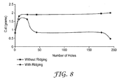
- FIG. 8 shows of graph of performance results.
- the abrasive articles converted (e.g., cut) through the back side first did not have ridging whereas the abrasive articles cut through the front side first did have ridging.
- the cut rate was significantly less (i.e., about 0.8 grams) for the abrasive articles that were cut first through the abrasive coating as compared to the abrasive articles cut first through the back side (i.e., about 2 grams). It is theorized that the dramatic loss of performance was due to the high ridges surrounding each aperture, which do not allow the tips of the abrasive particles to contact and thus effectively abrade the workpiece surface.
- the abrasive articles cut through the back side first did not have ridging whereas the abrasive articles cut through the front side first did have ridging.
- abrasive articles designated “373L” which are identical to “372L” abrasive articles, available from 3M Company, St. Paul, MN, except that the size coating thereon is colored), having abrasive particles of 15 to 200 micrometer, and also "360L", grades P220 to P1000, (also from 3M Company) having conventional make/size coatings and no supersize coating were laminated with an adhesive (identified below) using the conditions identified below.
- the adhesive was laminated to the backside of an abrasive article, opposite the abrasive surface.
- the laminated abrasive was perforated and cut into 5-inch diameter discs with a CO 2 laser through the back side (i.e., the adhesive side). Comparative examples were cut through the front side (i.e., the abrasive side).
- the abrasive articles cut through the back side first did not have ridging whereas the abrasive articles cut through the front side first did have ridging.
- Example 1 Several commercially abrasive articles (“360L" grade P800, from 3M Company) having conventional make/size coatings and no supersize coating were used as the basis for the following test.
- Example 2 the standard abrasive article, having no internal holes, was used.
- Example 2 a zinc stearate supersize coating was applied to an abrasive article having no internal holes.
- Example 3 internal vacuum holes were laser cut, through the back side, of an abrasive article having a zinc stearate supersize coating.
- Example 4 internal vacuum holes were laser cut, through the back side, of an abrasive article, after which a zinc stearate supersize coating was applied.
- the four examples were tested by the following procedure.
- the abrasive article was attached to a "Dynabrade” 5 inch back-up pad having 40 vacuum holes therein.
- a 40 hole "Dynabrade” 5 inch interface pad was also used.
- the back-up pad and abrasive article were attached to a "Dynabrade” 6 inch, pneumatic, self generated vacuum sander; the sander was operated at 90 psi air pressure.
- a clear coated test panel (from ACT Laboratories, "RK148") was sanded for 30 seconds with the abrasive article.
Landscapes
- Engineering & Computer Science (AREA)
- Mechanical Engineering (AREA)
- Polishing Bodies And Polishing Tools (AREA)
Abstract
Claims (10)
- Procédé de fabrication d'un article abrasif, comprenant :(a) le fait de disposer un revêtement abrasif sur un premier côté d'un support, le support ayant aussi un deuxième côté ; caractérisé par(b) la formation d'au moins 10 ouvertures à travers le support et le revêtement abrasif, chaque ouverture comportant une paroi latérale ; et(c) l'application d'un revêtement d'encollage supérieur comprenant un sel métallique d'un acide gras, le revêtement d'encollage supérieur étant présent sur le revêtement abrasif et les parois latérales.
- Procédé selon la revendication 1, dans lequel la formation d'au moins 10 ouvertures comprend :(a) le fait de concentrer une énergie laser sur le support, l'énergie laser traversant le deuxième côté du support avant de traverser le revêtement abrasif.
- Procédé selon la revendication 2, dans lequel la concentration de l'énergie laser sur le support comprend la concentration de l'énergie d'un laser CO2 à travers le support.
- Procédé selon la revendication 1, dans lequel le fait de disposer un revêtement abrasif sur un premier côté d'un support comprend le fait de disposer un revêtement abrasif formé comprenant des composites de forme précise.
- Procédé selon la revendication 1, dans lequel l'article abrasif comprend une région centrale comportant des ouvertures positionnées de façon aléatoire et une région extérieure annulaire comportant une pluralité d'ouvertures groupées le long d'un arc radial.
- Procédé selon la revendication 1, dans lequel le revêtement d'encollage supérieur comprend un stéarate.
- Procédé selon la revendication 1, dans lequel le revêtement abrasif comprend des particules abrasives ayant une taille inférieure à 40 micromètres et dans lequel la paroi latérale est fusionnée et ne s'étend pas sur plus de 10 micromètres au-dessus du revêtement abrasif.
- Procédé selon la revendication 1, dans lequel le revêtement abrasif comprend des particules abrasives ayant une taille inférieure à 35 micromètres et dans lequel la paroi latérale est fusionnée et ne s'étend pas sur plus de 10 micromètres au-dessus du revêtement abrasif.
- Procédé selon la revendication 1, dans lequel le revêtement abrasif comprend un revêtement abrasif formé comprenant des composites.
- Article abrasif pouvant être obtenu par le procédé selon l'une quelconque des revendications 1 à 9.
Applications Claiming Priority (3)
| Application Number | Priority Date | Filing Date | Title |
|---|---|---|---|
| US89300307P | 2007-03-05 | 2007-03-05 | |
| US11/781,598 US8080072B2 (en) | 2007-03-05 | 2007-07-23 | Abrasive article with supersize coating, and methods |
| PCT/US2008/052743 WO2008109211A1 (fr) | 2007-03-05 | 2008-02-01 | Article abrasif avec revêtement surdimensionné et procédé de fabrication |
Publications (2)
| Publication Number | Publication Date |
|---|---|
| EP2129491A1 EP2129491A1 (fr) | 2009-12-09 |
| EP2129491B1 true EP2129491B1 (fr) | 2012-08-15 |
Family
ID=39415225
Family Applications (1)
| Application Number | Title | Priority Date | Filing Date |
|---|---|---|---|
| EP08714158A Not-in-force EP2129491B1 (fr) | 2007-03-05 | 2008-02-01 | Article abrasif avec revêtement surdimensionné et procédé de fabrication |
Country Status (5)
| Country | Link |
|---|---|
| US (1) | US8080072B2 (fr) |
| EP (1) | EP2129491B1 (fr) |
| JP (1) | JP5340966B2 (fr) |
| KR (1) | KR101488037B1 (fr) |
| WO (1) | WO2008109211A1 (fr) |
Families Citing this family (29)
| Publication number | Priority date | Publication date | Assignee | Title |
|---|---|---|---|---|
| US7959694B2 (en) * | 2007-03-05 | 2011-06-14 | 3M Innovative Properties Company | Laser cut abrasive article, and methods |
| EP2459343B1 (fr) * | 2009-07-28 | 2020-06-17 | 3M Innovative Properties Company | Article abrasif revêtu et procédés d'ablation d'articles abrasifs revêtus |
| EP2498951A1 (fr) * | 2009-11-12 | 2012-09-19 | 3M Innovative Properties Company | Tampon lustreur rotatif |
| US9168636B2 (en) | 2009-12-22 | 2015-10-27 | 3M Innovative Properties Company | Flexible abrasive article and methods of making |
| US8932115B2 (en) * | 2010-10-15 | 2015-01-13 | 3M Innovative Properties Company | Abrasive articles |
| JP6392514B2 (ja) | 2010-12-30 | 2018-09-19 | スリーエム イノベイティブ プロパティズ カンパニー | レーザー切断方法及びこれにより製造された物品 |
| EP2551057B1 (fr) | 2011-07-25 | 2016-01-06 | sia Abrasives Industries AG | Procédé de fabrication d'un agent abrasif stratifié, agent abrasif stratifié et utilisation d'un agent abrasif stratifié |
| MX356390B (es) * | 2011-12-31 | 2018-05-28 | Saint Gobain Abrasives Inc | Artículo abrasivo que tiene una distribución no uniforme de aberturas. |
| FI2906392T3 (fi) * | 2012-10-15 | 2025-06-20 | Saint Gobain Abrasives Inc | Hiomahiukkasia, joilla on erityisiä muotoja, ja menetelmiä tällaisten hiukkasten muodostamiseksi |
| TWI589406B (zh) * | 2013-06-28 | 2017-07-01 | 聖高拜磨料有限公司 | 具有浮渣脊之研磨製品及其形成方法 |
| GB2515764A (en) * | 2013-07-02 | 2015-01-07 | 3M Innovative Properties Co | Abrasive article and adapter therefore |
| USD712443S1 (en) | 2013-07-02 | 2014-09-02 | 3M Innovative Properties Company | Abrasive article |
| JP6838811B2 (ja) * | 2014-05-02 | 2021-03-03 | スリーエム イノベイティブ プロパティズ カンパニー | 断続的構造化研磨物品並びに被加工物の研磨方法 |
| WO2017180468A1 (fr) * | 2016-04-13 | 2017-10-19 | 3M Innovative Properties Company | Article abrasif |
| US20180117705A1 (en) * | 2016-11-03 | 2018-05-03 | Menachem Margaliot | Device and method for laser processing of diamonds |
| BR112019013057B1 (pt) | 2016-12-23 | 2023-10-17 | Saint-Gobain Abrasives, Inc. | Abrasivos revestidos apresentando uma composição de melhoria de desempenho |
| US10835920B2 (en) * | 2018-08-03 | 2020-11-17 | Indian Institute Of Technology Ropar | Technology and process for coating a substrate with swarf particles |
| CN113195162A (zh) | 2018-12-18 | 2021-07-30 | 3M创新有限公司 | 图案化磨料基底和方法 |
| EP3898090A1 (fr) | 2018-12-18 | 2021-10-27 | 3M Innovative Properties Company | Article abrasif revêtu ayant des particules d'espacement, procédé de fabrication et appareil associé |
| WO2020128716A1 (fr) | 2018-12-18 | 2020-06-25 | 3M Innovative Properties Company | Dispositif de fabrication d'article abrasif à vitesse d'outillage différentielle |
| WO2020128854A1 (fr) * | 2018-12-18 | 2020-06-25 | 3M Innovative Properties Company | Remblai pour fixer une orientation pour une structure abrasive |
| CN113226645A (zh) | 2018-12-18 | 2021-08-06 | 3M创新有限公司 | 用于磨料制品的掩蔽 |
| US12017327B2 (en) | 2018-12-18 | 2024-06-25 | 3M Innovative Properties Company | Particle reception in abrasive article creation |
| WO2020128853A1 (fr) | 2018-12-18 | 2020-06-25 | 3M Innovative Properties Company | Réceptacle d'épissure d'outillage pour la production d'articles abrasifs |
| CN113195161A (zh) | 2018-12-18 | 2021-07-30 | 3M创新有限公司 | 成型磨料颗粒转移组件 |
| US20210197341A1 (en) * | 2019-12-25 | 2021-07-01 | Saint-Gobain Abrasives, Inc. | Coated abrasive with enhanced supersize composition |
| KR102545180B1 (ko) * | 2021-05-11 | 2023-06-20 | 주식회사 디어포스 | 멀티 집진홀 연마디스크 및 이를 이용가능한 연마패드 조립체 |
| FI130281B (en) * | 2021-11-25 | 2023-06-01 | Mirka Oy | Abrasive product |
| JP7714513B2 (ja) * | 2022-10-28 | 2025-07-29 | 株式会社コバックス | シート状研磨物品 |
Family Cites Families (38)
| Publication number | Priority date | Publication date | Assignee | Title |
|---|---|---|---|---|
| US2307312A (en) | 1941-09-04 | 1943-01-05 | Draper Corp | Abrading wheel |
| US2749681A (en) | 1952-12-31 | 1956-06-12 | Stephen U Sohne A | Grinding disc |
| US3866304A (en) | 1972-08-21 | 1975-02-18 | Alma A Hutchins | Method of piercing air suction holes in abrasive sheet material |
| US4311489A (en) | 1978-08-04 | 1982-01-19 | Norton Company | Coated abrasive having brittle agglomerates of abrasive grain |
| US4652274A (en) | 1985-08-07 | 1987-03-24 | Minnesota Mining And Manufacturing Company | Coated abrasive product having radiation curable binder |
| US4652275A (en) | 1985-08-07 | 1987-03-24 | Minnesota Mining And Manufacturing Company | Erodable agglomerates and abrasive products containing the same |
| US4799939A (en) | 1987-02-26 | 1989-01-24 | Minnesota Mining And Manufacturing Company | Erodable agglomerates and abrasive products containing the same |
| USD325774S (en) | 1987-07-30 | 1992-04-28 | CLM Investments, Inc. | Floor drain strainer |
| US5152917B1 (en) | 1991-02-06 | 1998-01-13 | Minnesota Mining & Mfg | Structured abrasive article |
| EP0660850B1 (fr) * | 1992-09-15 | 1996-06-05 | Minnesota Mining And Manufacturing Company | Abrasifs revetus prepares de compositions de revetements d'uree-aldehyde contenant un cocatalyseur et procedes de fabrication des abrasifs |
| US5435816A (en) | 1993-01-14 | 1995-07-25 | Minnesota Mining And Manufacturing Company | Method of making an abrasive article |
| US5549962A (en) | 1993-06-30 | 1996-08-27 | Minnesota Mining And Manufacturing Company | Precisely shaped particles and method of making the same |
| US5674122A (en) * | 1994-10-27 | 1997-10-07 | Minnesota Mining And Manufacturing Company | Abrasive articles and methods for their manufacture |
| US5533923A (en) | 1995-04-10 | 1996-07-09 | Applied Materials, Inc. | Chemical-mechanical polishing pad providing polishing unformity |
| US5578343A (en) | 1995-06-07 | 1996-11-26 | Norton Company | Mesh-backed abrasive products |
| DE29520566U1 (de) | 1995-12-29 | 1996-02-22 | Jöst, Peter, 69518 Abtsteinach | Direkt oder indirekt mit einer Maschine oder einem manuell betreibbaren Schleifmittelhalter adaptierbarer Schleifkörper sowie ein hierfür geeigneter Adapter |
| CN100361786C (zh) | 2000-12-21 | 2008-01-16 | 新日本制铁株式会社 | Cmp调节器、用于cmp调节器的硬质磨粒的排列方法以及cmp调节器的制造方法 |
| USD460767S1 (en) | 2001-02-15 | 2002-07-23 | Ehwa Diamond Ind. Co.,Ltd. | Saw blade |
| ATE453232T1 (de) | 2001-04-04 | 2010-01-15 | Coherent Deos | Gütegeschalteter co2 laser für materialbearbeitung |
| US7344432B2 (en) | 2001-04-24 | 2008-03-18 | Applied Materials, Inc. | Conductive pad with ion exchange membrane for electrochemical mechanical polishing |
| US7044989B2 (en) * | 2002-07-26 | 2006-05-16 | 3M Innovative Properties Company | Abrasive product, method of making and using the same, and apparatus for making the same |
| TWI238753B (en) | 2002-12-19 | 2005-09-01 | Miyanaga Kk | Diamond disk for grinding |
| US7040973B1 (en) | 2003-09-10 | 2006-05-09 | William Kitts | Abrasive sheet |
| KR100513402B1 (ko) | 2003-09-25 | 2005-09-09 | 삼성전자주식회사 | 화학적 기계적 연마 패드의 컨디셔너 클리닝장치 |
| US7150677B2 (en) | 2004-09-22 | 2006-12-19 | Mitsubishi Materials Corporation | CMP conditioner |
| NZ535658A (en) * | 2004-09-29 | 2007-10-26 | Millers Mechanical Nz Ltd | Apparatus for removing pelt from animal carcass with clamping means automatically varied to suit carcass shape and size |
| US7169029B2 (en) | 2004-12-16 | 2007-01-30 | 3M Innovative Properties Company | Resilient structured sanding article |
| US7252694B2 (en) * | 2005-08-05 | 2007-08-07 | 3M Innovative Properties Company | Abrasive article and methods of making same |
| US7497768B2 (en) * | 2005-08-11 | 2009-03-03 | 3M Innovative Properties Company | Flexible abrasive article and method of making |
| USD550819S1 (en) | 2005-08-23 | 2007-09-11 | Seehoff Gary S | Hair stopper |
| USD538312S1 (en) | 2005-09-16 | 2007-03-13 | 3M Innovative Properties Company | Abrasive article with holes |
| US7393269B2 (en) * | 2005-09-16 | 2008-07-01 | 3M Innovative Properties Company | Abrasive filter assembly and methods of making same |
| USD536714S1 (en) | 2005-09-16 | 2007-02-13 | 3M Innovative Properties Company | Abrasive article with holes |
| USD541317S1 (en) | 2006-02-01 | 2007-04-24 | 3M Innovative Properties Company | Abrasive article with holes |
| USD532800S1 (en) | 2006-02-01 | 2006-11-28 | 3M Innovative Properties Company | Abrasive article with holes |
| USD543562S1 (en) | 2006-02-01 | 2007-05-29 | 3M Innovative Properties Company | Abrasive article with holes |
| JP2008087082A (ja) | 2006-09-29 | 2008-04-17 | Three M Innovative Properties Co | 吸塵用研磨具 |
| US7959694B2 (en) | 2007-03-05 | 2011-06-14 | 3M Innovative Properties Company | Laser cut abrasive article, and methods |
-
2007
- 2007-07-23 US US11/781,598 patent/US8080072B2/en active Active
-
2008
- 2008-02-01 KR KR1020097020605A patent/KR101488037B1/ko not_active Expired - Fee Related
- 2008-02-01 JP JP2009552778A patent/JP5340966B2/ja active Active
- 2008-02-01 EP EP08714158A patent/EP2129491B1/fr not_active Not-in-force
- 2008-02-01 WO PCT/US2008/052743 patent/WO2008109211A1/fr not_active Ceased
Also Published As
| Publication number | Publication date |
|---|---|
| EP2129491A1 (fr) | 2009-12-09 |
| WO2008109211A1 (fr) | 2008-09-12 |
| JP2010520078A (ja) | 2010-06-10 |
| KR101488037B1 (ko) | 2015-01-29 |
| US8080072B2 (en) | 2011-12-20 |
| JP5340966B2 (ja) | 2013-11-13 |
| KR20100015335A (ko) | 2010-02-12 |
| US20080216413A1 (en) | 2008-09-11 |
Similar Documents
| Publication | Publication Date | Title |
|---|---|---|
| EP2129491B1 (fr) | Article abrasif avec revêtement surdimensionné et procédé de fabrication | |
| US7959694B2 (en) | Laser cut abrasive article, and methods | |
| KR101085771B1 (ko) | 포물선 측부를 갖는 구조화된 연마제 | |
| JP5597140B2 (ja) | プラズマ処理された研磨物品及び同物品の作製方法 | |
| EP0719200B1 (fr) | Articles abrasifs ainsi que leurs procedes de fabrication et d'utilisation | |
| US20050064805A1 (en) | Structured abrasive article | |
| US20050060941A1 (en) | Abrasive article and methods of making the same | |
| JPH07247477A (ja) | 被覆性組成物、それらから製造した研磨物品、およびその製造および使用方法 | |
| JPH07164330A (ja) | 研磨材物品およびその製造方法 | |
| CN1767926A (zh) | 制造磨具的方法 | |
| EP1102660B1 (fr) | Article abrasif presentant des parties saillantes sur la surface avant formees separement contenant un agent de meulage et procedes de production | |
| CN105636746B (zh) | 涂覆磨料制品及其制备方法 | |
| EP1670617B1 (fr) | Procédé de fabrication des articles abrasifs revêtus | |
| US20050060945A1 (en) | Method of making a coated abrasive | |
| US20050060944A1 (en) | Method of making a coated abrasive |
Legal Events
| Date | Code | Title | Description |
|---|---|---|---|
| PUAI | Public reference made under article 153(3) epc to a published international application that has entered the european phase |
Free format text: ORIGINAL CODE: 0009012 |
|
| 17P | Request for examination filed |
Effective date: 20090918 |
|
| AK | Designated contracting states |
Kind code of ref document: A1 Designated state(s): AT BE BG CH CY CZ DE DK EE ES FI FR GB GR HR HU IE IS IT LI LT LU LV MC MT NL NO PL PT RO SE SI SK TR |
|
| DAX | Request for extension of the european patent (deleted) | ||
| 17Q | First examination report despatched |
Effective date: 20101201 |
|
| GRAP | Despatch of communication of intention to grant a patent |
Free format text: ORIGINAL CODE: EPIDOSNIGR1 |
|
| GRAS | Grant fee paid |
Free format text: ORIGINAL CODE: EPIDOSNIGR3 |
|
| GRAA | (expected) grant |
Free format text: ORIGINAL CODE: 0009210 |
|
| AK | Designated contracting states |
Kind code of ref document: B1 Designated state(s): AT BE BG CH CY CZ DE DK EE ES FI FR GB GR HR HU IE IS IT LI LT LU LV MC MT NL NO PL PT RO SE SI SK TR |
|
| REG | Reference to a national code |
Ref country code: CH Ref legal event code: EP Ref country code: AT Ref legal event code: REF Ref document number: 570560 Country of ref document: AT Kind code of ref document: T Effective date: 20120815 Ref country code: GB Ref legal event code: FG4D |
|
| REG | Reference to a national code |
Ref country code: IE Ref legal event code: FG4D |
|
| REG | Reference to a national code |
Ref country code: DE Ref legal event code: R096 Ref document number: 602008018012 Country of ref document: DE Effective date: 20121011 |
|
| REG | Reference to a national code |
Ref country code: NL Ref legal event code: VDEP Effective date: 20120815 |
|
| REG | Reference to a national code |
Ref country code: AT Ref legal event code: MK05 Ref document number: 570560 Country of ref document: AT Kind code of ref document: T Effective date: 20120815 |
|
| PG25 | Lapsed in a contracting state [announced via postgrant information from national office to epo] |
Ref country code: FI Free format text: LAPSE BECAUSE OF FAILURE TO SUBMIT A TRANSLATION OF THE DESCRIPTION OR TO PAY THE FEE WITHIN THE PRESCRIBED TIME-LIMIT Effective date: 20120815 Ref country code: CY Free format text: LAPSE BECAUSE OF FAILURE TO SUBMIT A TRANSLATION OF THE DESCRIPTION OR TO PAY THE FEE WITHIN THE PRESCRIBED TIME-LIMIT Effective date: 20120815 Ref country code: HR Free format text: LAPSE BECAUSE OF FAILURE TO SUBMIT A TRANSLATION OF THE DESCRIPTION OR TO PAY THE FEE WITHIN THE PRESCRIBED TIME-LIMIT Effective date: 20120815 Ref country code: AT Free format text: LAPSE BECAUSE OF FAILURE TO SUBMIT A TRANSLATION OF THE DESCRIPTION OR TO PAY THE FEE WITHIN THE PRESCRIBED TIME-LIMIT Effective date: 20120815 Ref country code: LT Free format text: LAPSE BECAUSE OF FAILURE TO SUBMIT A TRANSLATION OF THE DESCRIPTION OR TO PAY THE FEE WITHIN THE PRESCRIBED TIME-LIMIT Effective date: 20120815 Ref country code: NO Free format text: LAPSE BECAUSE OF FAILURE TO SUBMIT A TRANSLATION OF THE DESCRIPTION OR TO PAY THE FEE WITHIN THE PRESCRIBED TIME-LIMIT Effective date: 20121115 Ref country code: IS Free format text: LAPSE BECAUSE OF FAILURE TO SUBMIT A TRANSLATION OF THE DESCRIPTION OR TO PAY THE FEE WITHIN THE PRESCRIBED TIME-LIMIT Effective date: 20121215 |
|
| PG25 | Lapsed in a contracting state [announced via postgrant information from national office to epo] |
Ref country code: PL Free format text: LAPSE BECAUSE OF FAILURE TO SUBMIT A TRANSLATION OF THE DESCRIPTION OR TO PAY THE FEE WITHIN THE PRESCRIBED TIME-LIMIT Effective date: 20120815 Ref country code: PT Free format text: LAPSE BECAUSE OF FAILURE TO SUBMIT A TRANSLATION OF THE DESCRIPTION OR TO PAY THE FEE WITHIN THE PRESCRIBED TIME-LIMIT Effective date: 20121217 Ref country code: SI Free format text: LAPSE BECAUSE OF FAILURE TO SUBMIT A TRANSLATION OF THE DESCRIPTION OR TO PAY THE FEE WITHIN THE PRESCRIBED TIME-LIMIT Effective date: 20120815 Ref country code: SE Free format text: LAPSE BECAUSE OF FAILURE TO SUBMIT A TRANSLATION OF THE DESCRIPTION OR TO PAY THE FEE WITHIN THE PRESCRIBED TIME-LIMIT Effective date: 20120815 Ref country code: BE Free format text: LAPSE BECAUSE OF FAILURE TO SUBMIT A TRANSLATION OF THE DESCRIPTION OR TO PAY THE FEE WITHIN THE PRESCRIBED TIME-LIMIT Effective date: 20120815 Ref country code: LV Free format text: LAPSE BECAUSE OF FAILURE TO SUBMIT A TRANSLATION OF THE DESCRIPTION OR TO PAY THE FEE WITHIN THE PRESCRIBED TIME-LIMIT Effective date: 20120815 Ref country code: GR Free format text: LAPSE BECAUSE OF FAILURE TO SUBMIT A TRANSLATION OF THE DESCRIPTION OR TO PAY THE FEE WITHIN THE PRESCRIBED TIME-LIMIT Effective date: 20121116 |
|
| PG25 | Lapsed in a contracting state [announced via postgrant information from national office to epo] |
Ref country code: NL Free format text: LAPSE BECAUSE OF FAILURE TO SUBMIT A TRANSLATION OF THE DESCRIPTION OR TO PAY THE FEE WITHIN THE PRESCRIBED TIME-LIMIT Effective date: 20120815 |
|
| PG25 | Lapsed in a contracting state [announced via postgrant information from national office to epo] |
Ref country code: RO Free format text: LAPSE BECAUSE OF FAILURE TO SUBMIT A TRANSLATION OF THE DESCRIPTION OR TO PAY THE FEE WITHIN THE PRESCRIBED TIME-LIMIT Effective date: 20120815 Ref country code: EE Free format text: LAPSE BECAUSE OF FAILURE TO SUBMIT A TRANSLATION OF THE DESCRIPTION OR TO PAY THE FEE WITHIN THE PRESCRIBED TIME-LIMIT Effective date: 20120815 Ref country code: CZ Free format text: LAPSE BECAUSE OF FAILURE TO SUBMIT A TRANSLATION OF THE DESCRIPTION OR TO PAY THE FEE WITHIN THE PRESCRIBED TIME-LIMIT Effective date: 20120815 Ref country code: DK Free format text: LAPSE BECAUSE OF FAILURE TO SUBMIT A TRANSLATION OF THE DESCRIPTION OR TO PAY THE FEE WITHIN THE PRESCRIBED TIME-LIMIT Effective date: 20120815 Ref country code: ES Free format text: LAPSE BECAUSE OF FAILURE TO SUBMIT A TRANSLATION OF THE DESCRIPTION OR TO PAY THE FEE WITHIN THE PRESCRIBED TIME-LIMIT Effective date: 20121126 |
|
| PG25 | Lapsed in a contracting state [announced via postgrant information from national office to epo] |
Ref country code: IT Free format text: LAPSE BECAUSE OF FAILURE TO SUBMIT A TRANSLATION OF THE DESCRIPTION OR TO PAY THE FEE WITHIN THE PRESCRIBED TIME-LIMIT Effective date: 20120815 Ref country code: SK Free format text: LAPSE BECAUSE OF FAILURE TO SUBMIT A TRANSLATION OF THE DESCRIPTION OR TO PAY THE FEE WITHIN THE PRESCRIBED TIME-LIMIT Effective date: 20120815 |
|
| PLBE | No opposition filed within time limit |
Free format text: ORIGINAL CODE: 0009261 |
|
| STAA | Information on the status of an ep patent application or granted ep patent |
Free format text: STATUS: NO OPPOSITION FILED WITHIN TIME LIMIT |
|
| 26N | No opposition filed |
Effective date: 20130516 |
|
| PG25 | Lapsed in a contracting state [announced via postgrant information from national office to epo] |
Ref country code: BG Free format text: LAPSE BECAUSE OF FAILURE TO SUBMIT A TRANSLATION OF THE DESCRIPTION OR TO PAY THE FEE WITHIN THE PRESCRIBED TIME-LIMIT Effective date: 20121115 |
|
| REG | Reference to a national code |
Ref country code: DE Ref legal event code: R097 Ref document number: 602008018012 Country of ref document: DE Effective date: 20130516 |
|
| PG25 | Lapsed in a contracting state [announced via postgrant information from national office to epo] |
Ref country code: MC Free format text: LAPSE BECAUSE OF NON-PAYMENT OF DUE FEES Effective date: 20130228 |
|
| REG | Reference to a national code |
Ref country code: CH Ref legal event code: PL |
|
| GBPC | Gb: european patent ceased through non-payment of renewal fee |
Effective date: 20130201 |
|
| PG25 | Lapsed in a contracting state [announced via postgrant information from national office to epo] |
Ref country code: CH Free format text: LAPSE BECAUSE OF NON-PAYMENT OF DUE FEES Effective date: 20130228 Ref country code: LI Free format text: LAPSE BECAUSE OF NON-PAYMENT OF DUE FEES Effective date: 20130228 |
|
| REG | Reference to a national code |
Ref country code: FR Ref legal event code: ST Effective date: 20131031 |
|
| REG | Reference to a national code |
Ref country code: IE Ref legal event code: MM4A |
|
| PG25 | Lapsed in a contracting state [announced via postgrant information from national office to epo] |
Ref country code: GB Free format text: LAPSE BECAUSE OF NON-PAYMENT OF DUE FEES Effective date: 20130201 Ref country code: IE Free format text: LAPSE BECAUSE OF NON-PAYMENT OF DUE FEES Effective date: 20130201 Ref country code: FR Free format text: LAPSE BECAUSE OF NON-PAYMENT OF DUE FEES Effective date: 20130228 |
|
| PG25 | Lapsed in a contracting state [announced via postgrant information from national office to epo] |
Ref country code: MT Free format text: LAPSE BECAUSE OF FAILURE TO SUBMIT A TRANSLATION OF THE DESCRIPTION OR TO PAY THE FEE WITHIN THE PRESCRIBED TIME-LIMIT Effective date: 20120815 |
|
| PG25 | Lapsed in a contracting state [announced via postgrant information from national office to epo] |
Ref country code: TR Free format text: LAPSE BECAUSE OF FAILURE TO SUBMIT A TRANSLATION OF THE DESCRIPTION OR TO PAY THE FEE WITHIN THE PRESCRIBED TIME-LIMIT Effective date: 20120815 |
|
| PG25 | Lapsed in a contracting state [announced via postgrant information from national office to epo] |
Ref country code: LU Free format text: LAPSE BECAUSE OF NON-PAYMENT OF DUE FEES Effective date: 20130201 Ref country code: HU Free format text: LAPSE BECAUSE OF FAILURE TO SUBMIT A TRANSLATION OF THE DESCRIPTION OR TO PAY THE FEE WITHIN THE PRESCRIBED TIME-LIMIT; INVALID AB INITIO Effective date: 20080201 |
|
| PGFP | Annual fee paid to national office [announced via postgrant information from national office to epo] |
Ref country code: DE Payment date: 20220119 Year of fee payment: 15 |
|
| REG | Reference to a national code |
Ref country code: DE Ref legal event code: R119 Ref document number: 602008018012 Country of ref document: DE |
|
| PG25 | Lapsed in a contracting state [announced via postgrant information from national office to epo] |
Ref country code: DE Free format text: LAPSE BECAUSE OF NON-PAYMENT OF DUE FEES Effective date: 20230901 |