EP2129477B1 - Dispositif de filtration - Google Patents
Dispositif de filtration Download PDFInfo
- Publication number
- EP2129477B1 EP2129477B1 EP08734932.0A EP08734932A EP2129477B1 EP 2129477 B1 EP2129477 B1 EP 2129477B1 EP 08734932 A EP08734932 A EP 08734932A EP 2129477 B1 EP2129477 B1 EP 2129477B1
- Authority
- EP
- European Patent Office
- Prior art keywords
- sieve
- bar
- screen
- accordance
- Prior art date
- Legal status (The legal status is an assumption and is not a legal conclusion. Google has not performed a legal analysis and makes no representation as to the accuracy of the status listed.)
- Revoked
Links
Images

Classifications
-
- D—TEXTILES; PAPER
- D21—PAPER-MAKING; PRODUCTION OF CELLULOSE
- D21D—TREATMENT OF THE MATERIALS BEFORE PASSING TO THE PAPER-MAKING MACHINE
- D21D5/00—Purification of the pulp suspension by mechanical means; Apparatus therefor
- D21D5/02—Straining or screening the pulp
- D21D5/16—Cylinders and plates for screens
-
- B—PERFORMING OPERATIONS; TRANSPORTING
- B01—PHYSICAL OR CHEMICAL PROCESSES OR APPARATUS IN GENERAL
- B01D—SEPARATION
- B01D29/00—Filters with filtering elements stationary during filtration, e.g. pressure or suction filters, not covered by groups B01D24/00 - B01D27/00; Filtering elements therefor
- B01D29/44—Edge filtering elements, i.e. using contiguous impervious surfaces
- B01D29/445—Bar screens
-
- B—PERFORMING OPERATIONS; TRANSPORTING
- B01—PHYSICAL OR CHEMICAL PROCESSES OR APPARATUS IN GENERAL
- B01D—SEPARATION
- B01D33/00—Filters with filtering elements which move during the filtering operation
- B01D33/06—Filters with filtering elements which move during the filtering operation with rotary cylindrical filtering surfaces, e.g. hollow drums
- B01D33/073—Filters with filtering elements which move during the filtering operation with rotary cylindrical filtering surfaces, e.g. hollow drums arranged for inward flow filtration
-
- B—PERFORMING OPERATIONS; TRANSPORTING
- B07—SEPARATING SOLIDS FROM SOLIDS; SORTING
- B07B—SEPARATING SOLIDS FROM SOLIDS BY SIEVING, SCREENING, SIFTING OR BY USING GAS CURRENTS; SEPARATING BY OTHER DRY METHODS APPLICABLE TO BULK MATERIAL, e.g. LOOSE ARTICLES FIT TO BE HANDLED LIKE BULK MATERIAL
- B07B1/00—Sieving, screening, sifting, or sorting solid materials using networks, gratings, grids, or the like
- B07B1/12—Apparatus having only parallel elements
-
- B—PERFORMING OPERATIONS; TRANSPORTING
- B07—SEPARATING SOLIDS FROM SOLIDS; SORTING
- B07B—SEPARATING SOLIDS FROM SOLIDS BY SIEVING, SCREENING, SIFTING OR BY USING GAS CURRENTS; SEPARATING BY OTHER DRY METHODS APPLICABLE TO BULK MATERIAL, e.g. LOOSE ARTICLES FIT TO BE HANDLED LIKE BULK MATERIAL
- B07B1/00—Sieving, screening, sifting, or sorting solid materials using networks, gratings, grids, or the like
- B07B1/46—Constructional details of screens in general; Cleaning or heating of screens
- B07B1/4609—Constructional details of screens in general; Cleaning or heating of screens constructional details of screening surfaces or meshes
- B07B1/4618—Manufacturing of screening surfaces
Definitions
- the invention relates to a sieve device in which sieve slots or sieve gaps are formed between preferably profiled sieve bars, which are received at their base area in relation to receiving recesses of support elements and permanently secured thereto.
- Such screening devices are also referred to as "bar screen devices”. These screening devices can be configured in flat form as sieve plates or in rounded form as sieve baskets.
- a soldering process in particular brazing is described as suitable and another, suitable, high-quality soldering is vacuum brazing, which gives a high-quality permanent connection of screen bars and support elements, but this is very expensive to manufacture.
- To produce such a screen basket are formed in a framework of support elements, there as a support rings, inserted as screen bars profile bars and first festgeat by a welding process and then welded.
- the screen bars are hereby welded contour-wise, ie substantially along the edges of the receiving recesses. Furthermore, there is mentioned that you can connect these screen bars by gluing with the support elements.
- a screen basket according to the preamble of claim 1 is known in which the welding is to be avoided and yet a clear definition of the screen bars in the support elements to be made possible.
- the connection between the individual screen bars and the support elements is designed as a snap connection, so that one can press the screen bars transversely to the longitudinal extension of the support elements in this.
- a matching vote of Siebstabprofil and receiving recesses in the support member is required to clamp the Siebstabprofilquerroughe firmly in the receiving recesses of the support elements.
- the support members are held parallel to each other with mutual, the distance of the support members corresponding distance in a device, and then the screen bars are pressed one after the other into the receiving recesses of all supporting elements simultaneously. Also, one can provide in the preparation of a counter bending to slightly widen the receiving recesses and thereby facilitate the insertion of the screen bars. If there are gaps between the screen and the support after bending, they will be sealed with liquid plastic (Loctite) to avoid the risk of plait.
- Lictite liquid plastic
- Adhesive can be used, which allows production at relatively low temperatures.
- a two-component technical adhesive may be considered, in the use of which the clamping forces between screen bars in the foot region and in the receiving recesses of the carrier elements are retained.
- the invention therefore aims to provide a screening device, i. to provide a so-called “Stabsiebvoriques” in which overcoming the difficulties previously described in terms of design and manufacturing technology as efficiently as possible, a reliable, permanent solid connection between the support elements and the associated screen bars is achieved.
- a screening device according to claim 1 is provided for this purpose.
- a pocket or a pocket-shaped intermediate space is thus formed at least on the flank region between the profile bar outer surface and the receiving recess in a defined manner, which is then filled with a suitable filling material after insertion of the respective screen into the respectively associated receiving recess of the support element to get a permanent and firm connection between the screen tab and the associated receiving recess of the support element.
- the screen slot or screen gap formed at the head area between adjacent screen bars can be formed largely uniformly and in a predetermined manner over the entire circumference of the screening device with extremely high repetition accuracy, so that a high-quality product in the form of a screening device is obtained during operation.
- the envisaged in the invention targeted training of the pockets also allows a largely variable choice of the number of pockets in the flank area and the size thereof and a corresponding position thereof, so that reliable after filling the respective bag with filler a permanent and solid compound of each Siebstabs and can ensure a reliable and accurate alignment in the respective receiving recess of the support element.
- the at least one pocket can be formed by a corresponding shaping of the screen foot region and a corresponding shaping of the receiving recess in the respective support element or else by the combination of both.
- the vertical range of manufacture can also be matched to the desired and desired requirements with regard to accuracy and strength to the respective application.
- the sieve height is in a range of 3 mm to 25 mm, in particular from 5 mm to 18 mm.
- this overlap region is in a range of 4 mm to 50 mm, preferably in a range of 6 mm to 25 mm.
- the respective pocket has a transverse extension of 0.05 to 2.0 mm, preferably from 0.1 to 0.5 mm, so that the bag provides sufficient space for the subsequent inclusion of the filling material and thereby a safe, reliable and durable firm connection of screen and support element is given.
- the flank region of the respective receiving recess comprises at least one pocket with a pocket surface and at least one support surface for the sieve tab, so that the flank region reliably performs the dual function of aligning the respective sieve tab and the receiving recess as well as producing the firm connection by filling the pocket with filling material can fulfill.
- the ratio of the sum of the bearing surfaces to the sum of the pocket surfaces in a range of 0.1 to 1.0. If the bearing surfaces are spaced as far as possible from each other, it can be ensured in the receiving recess precise guidance of the screen bar.
- the at least one pocket by at least one recess in the sieve or in the receiving recess of the support element or also formed by both, preferably in the flank area.
- the bag may optionally be formed without additional processing on the receiving recesses and / or the Siebbstfuß Scheme because at least one bag alone by the appropriate choice of the geometry of the profiles of sieve and receiving recess when joining the two parts results.
- the number and shape of the at least one pocket can be chosen largely freely, but it has proved to be particularly advantageous if the bag has a V-shaped cross-section, which then simplify the filling process with the filler and in particular reliably ensures in that the entire bag volume can be completely filled with the filling material.
- the foot portion of the screen tab is approximately V-shaped, whereby a reliable centering of the screen tab is achieved in the associated receiving recess. This also facilitates manufacturing automation.
- an adhesive filling material in the pocket (s) is introduced, which then hardens, so that forms a kind of Klebstoffpfropfen in the bag, which can reliably absorb shear forces and the like.
- a clip-shaped interlocking element made of a suitable material can be introduced into the at least one pocket, by means of which the respective sieve strip is temporarily fixed in the respective support element in order to be able to suitably manufacture the sieve slots or gaps formed by the sieve device then the bag is then completely filled with the filling material.
- a pocket which can be filled with filling material can be provided on the foot region of the respective screen tab and the base of the receiving recess in the respective support element. In this way, in addition, too at the foot, or only on this, an effective tension between receiving recess and Siebstabfuß be achieved.
- At least one pocket is provided on the opposite flank areas, which can then be filled with filler. In this way it is achieved that the screen bar can be permanently and precisely aligned centrally in the receiving recess of the support element.
- the support elements can be designed as support rings, so that the sieve device as a whole has a cylindrical outer shape.
- the support elements are designed in the form of a support bar and this can then be rounded before or after the assembly with sieve bars, for example, to a cylindrical shape.
- a pocket or a pocket-shaped cavity is provided, which is filled with a filler which homogeneous and uniform or from combined fastening means may be formed composite.
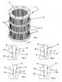
- FIG. 1 a cylindrical screen basket 2 is shown.
- the screening device 1 according to the invention can also be designed in the form of a screen plate.
- the screening device 1 comprises supporting elements 3, which are formed in the illustrated example as supporting rings 4, and at the axial end portions of the screening device 1 so-called end flanges 5 are provided.
- Sieve bars 6 are inserted into corresponding receiving recesses of the support element 3, between the top regions of each of which a screen slot or sieve gap is formed.
- Stabsiebkorb is known per se.
- FIGS. 2 to 10 schematically shows a section of a support member 3 and a screen bar 6 to illustrate the permanent solid connection of these two parts.
- the pocket 10 or the pockets 10, which lie opposite one another, are formed by a corresponding recess in the flank region 7 of the support element 3.
- the associated foot area of the screen bar 6 is prefabricated without any additional processing and may be a predetermined, rolled screen material, which is then cut to the desired lengths.
- the pocket (s) 10 is formed in opposite flank regions 7 by associated recesses on the support element 3 and on the foot region of the screen 6. In such an embodiment, one can create large-volume pockets 10, which are then filled with a filling material, such as adhesive or the like. This makes it possible to realize pockets 10 which have relatively large transverse extensions.
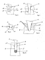
- the pockets 10 are formed by the corresponding geometric shape in adaptation of outer profile of the screen bar 6 and the profile of the receiving recess 8 in the support member 3. Also in FIG. 7 one obtains the bag or the pockets 10 by appropriate embodiments of receiving recesses 8 on the support element 3 and outer geometry of the screen bar 6, wherein in FIG. 7 the outer profile of the screen bar is modified in such a way that it forms the pocket 10 in the flank region, when the receiving recess 8 is introduced in the support element 3 in a substantially conventional manner.
- FIG. 8 serves to illustrate a variant embodiment in which at least one pocket 10 is formed at the foot of each Siebstabs 6, said pockets 10 can clamp the associated sieve in the receiving recess 8 in the support element in a suitable manner with appropriate filling material and fastening means.
- FIG. 9 illustrates in cross-section substantially V-shaped or triangular-shaped pockets 10, which are cut in a suitable manner in the inner wall of the receiving recess 8 of the support member 3.
- FIG. 10 illustrates a further embodiment, in which a pocket 10 is formed on the flank region 7, but also at the foot of the screen bar 6 an additional 11 is provided as a gap between the bottom of the receiving recess 8 of the support member 3 and the screen foot.
- a clip-shaped positive locking element can be used to the primary fixation of the screen bar 6 in the receiving recess 8.
- FIGS. 11 to 13 preferred geometric proportions are illustrated and explained in the screening device according to the invention.
- a screen bar 6 is shown having a height, which is about 3 mm to 25 mm, and preferably in a range of 5 mm and 18 mm.
- an overlap extension between the support member 3 and the screen bar 6 of 4 mm to 50 mm, and in particular from 6 mm to 25 mm.
- C is defined as the ratio of the sum of the bearing surfaces divided by the sum of the pocket areas.
- the ratio C is in a range of 0.1 to 1.0.
- FIG. 13 serves to illustrate the dimensions of the respective pocket 10.
- Each pocket 10 has a longitudinal extent and a transverse extent.
- the transverse extent is preferably in a range of 0.05 mm to 2.0 mm, and more preferably in a range of 0.1 mm to 0.5 mm.
Landscapes
- Chemical & Material Sciences (AREA)
- Chemical Kinetics & Catalysis (AREA)
- Engineering & Computer Science (AREA)
- Mechanical Engineering (AREA)
- Manufacturing & Machinery (AREA)
- Combined Means For Separation Of Solids (AREA)
- Filtering Materials (AREA)
- Filtration Of Liquid (AREA)
- Analysing Materials By The Use Of Radiation (AREA)
- Developing Agents For Electrophotography (AREA)
Claims (11)
- Dispositif de tamisage avec des fentes ou interstices de tamisage formés entre des barres de tamis (6), de préférence profilées, les barres de tamis (6) étant reçues, au niveau de leur zone de base, dans des cavités de réception (8), adaptées à la géométrie de leur zone de base, d'éléments porteurs (3), et fixées à demeure à celles-ci, entre chaque élément porteur (3) et chaque barre de tamis associée (6) étant prévue, au moins au niveau de la zone de flanc (7) formant des surfaces d'appui pour la barre de tamis (6) de la cavité de réception respective (8), une poche (10) pouvant être remplie d'une matière de remplissage, la barre de tamis (6) présentant une hauteur de barre de tamis de 3 à 25 mm, de préférence de 5 à 18 mm, caractérisé en ce que C, défini comme étant le rapport résultant de la somme des surfaces d'appui pour la barre de tamis (6) divisée par la somme des surfaces de poche, se situe dans une plage de 0,1 à 1,0.
- Dispositif de tamisage suivant la revendication 1, caractérisé en ce que l'au moins une poche (10) est formée par une conception correspondante de la cavité de réception (8) dans l'élément porteur respectif (3).
- Dispositif de tamisage suivant la revendication 1 ou 2, caractérisé en ce que de la forme de la barre de tamis (2) résulte un chevauchement entre celle-ci et l'élément porteur (3) respectif, chevauchement qui se situe dans une plage de 4 mm à 50 mm, de préférence, de 6 à 25 mm.
- Dispositif de tamisage suivant une des revendications 1 à 3, caractérisé en ce que la poche respective (10) présente une dimension transversale de 0,05 à 2,0 mm, de préférence, de 0,01 à 0,5 mm.
- Dispositif de tamisage suivant une des revendications 1 à 4, caractérisé en ce que l'au moins une poche (10) est formée par au moins un évidement dans la barre de tamis (6) et/ou dans la cavité de réception (8) de l'élément porteur (3), de préférence, dans la zone de flanc (7).
- Dispositif de tamisage suivant une des revendications précédentes, caractérisé en ce que la zone de base de la barre de tamis (6) est conçue essentiellement en forme de V.
- Dispositif de tamisage suivant une des revendications précédentes, caractérisé en ce que la matière de remplissage est un adhésif.
- Dispositif de tamisage suivant une des revendications précédentes, caractérisé en ce qu'au moins une poche supplémentaire (11) pouvant être remplie de matière de remplissage est prévue dans la zone de base de la barre de tamis respective (6) et de la cavité de réception (8) dans l'élément porteur respectif (3).
- Dispositif de tamisage suivant une des revendications précédentes, caractérisé en ce qu'au moins une poche (10) est prévue au niveau des zones de flanc opposées (7) et des cavités de réception respectives (8) dans l'élément porteur (3) et de la barre de tamis respectivement associée (6).
- Dispositif de tamisage suivant une des revendications précédentes, caractérisé en ce que les éléments porteurs (3) sont conçus comme anneaux porteurs (4).
- Dispositif de tamisage suivant une des revendications précédentes, caractérisé en ce que le dispositif de tamisage est conçu comme cylindre de tamisage ou panier de tamisage (2), de préférence comme panier de tamisage à barres de tamis.
Applications Claiming Priority (2)
| Application Number | Priority Date | Filing Date | Title |
|---|---|---|---|
| DE102007015901.5A DE102007015901B4 (de) | 2007-04-02 | 2007-04-02 | Siebvorrichtung |
| PCT/EP2008/002580 WO2008119548A2 (fr) | 2007-04-02 | 2008-04-01 | Dispositif de filtration |
Publications (2)
| Publication Number | Publication Date |
|---|---|
| EP2129477A2 EP2129477A2 (fr) | 2009-12-09 |
| EP2129477B1 true EP2129477B1 (fr) | 2015-07-08 |
Family
ID=39736088
Family Applications (1)
| Application Number | Title | Priority Date | Filing Date |
|---|---|---|---|
| EP08734932.0A Revoked EP2129477B1 (fr) | 2007-04-02 | 2008-04-01 | Dispositif de filtration |
Country Status (8)
| Country | Link |
|---|---|
| US (1) | US8292086B2 (fr) |
| EP (1) | EP2129477B1 (fr) |
| CN (1) | CN101657269B (fr) |
| CA (1) | CA2677927C (fr) |
| DE (1) | DE102007015901B4 (fr) |
| ES (1) | ES2548523T3 (fr) |
| TW (1) | TW200900129A (fr) |
| WO (1) | WO2008119548A2 (fr) |
Families Citing this family (11)
| Publication number | Priority date | Publication date | Assignee | Title |
|---|---|---|---|---|
| DE102013010959B3 (de) | 2013-07-01 | 2014-08-07 | Andritz Fiedler Gmbh | Siebvorrichtung |
| DE102014011679A1 (de) | 2013-08-20 | 2015-02-26 | Andritz Fiedler Gmbh | Profilierter Siebstab und Siebvorrichtung aus profilierten Siebstäben |
| DE102014009588A1 (de) | 2014-06-27 | 2016-01-14 | Andritz Fiedler Gmbh | Garnitur für das mechanische Bearbeiten, insbesondere Mahlen von suspendiertem Faserstoffmaterial |
| DE102015003020B3 (de) | 2015-03-06 | 2016-03-03 | Andritz Fiedler Gmbh | Stabsiebkorb |
| CN106925508A (zh) * | 2017-04-11 | 2017-07-07 | 中国科学院近代物理研究所 | 一种高温真空颗粒筛选机 |
| CN107142771A (zh) * | 2017-05-31 | 2017-09-08 | 瑞安市金邦喷淋技术有限公司 | 造纸机的筛鼓 |
| CN107142770A (zh) * | 2017-05-31 | 2017-09-08 | 瑞安市金邦喷淋技术有限公司 | 造纸机筛鼓的法兰盘与导流筛棒的连接结构 |
| DE102018005307B3 (de) * | 2018-07-04 | 2019-06-06 | Andritz Fiedler Gmbh | Siebvorrichtung |
| RU2732749C1 (ru) * | 2020-03-11 | 2020-09-22 | Евгений Иванович ВЕРХОЛОМОВ | Щелевой фильтр |
| JP6734496B1 (ja) * | 2020-04-17 | 2020-08-05 | 三菱重工環境・化学エンジニアリング株式会社 | スクリーン装置、濃縮システム及び脱水システム並びに水処理システム |
| CH719918B1 (de) * | 2022-07-22 | 2025-08-15 | Elsener Erwin | Aufsatz für ein Abflussrohr eines Wasserbeckens. |
Citations (3)
| Publication number | Priority date | Publication date | Assignee | Title |
|---|---|---|---|---|
| EP0499154A1 (fr) | 1991-02-15 | 1992-08-19 | J.M. Voith GmbH | Epurateur |
| EP0808941A1 (fr) | 1996-05-24 | 1997-11-26 | Voith Sulzer Stoffaufbereitung GmbH | Procédé de fabrication d'un appareil de tamisage à ouvertures en forme de fentes et appareil de tamisage produit par ce procédé |
| JP2001200488A (ja) | 2000-01-18 | 2001-07-27 | Mitsubishi Heavy Ind Ltd | スクリーンシリンダ |
Family Cites Families (16)
| Publication number | Priority date | Publication date | Assignee | Title |
|---|---|---|---|---|
| DE1117513B (de) | 1958-01-08 | 1961-11-23 | Haver & Boecker | Spaltsieb |
| US3901801A (en) | 1974-06-17 | 1975-08-26 | Hendrick Mfg Co | Industrial screen |
| JPH0536483Y2 (fr) * | 1986-07-04 | 1993-09-16 | ||
| DE3816152A1 (de) | 1987-11-14 | 1989-11-23 | Voith Gmbh J M | Siebkorb und verfahren zu dessen herstellung |
| DE3927748C2 (de) | 1989-08-23 | 1994-03-10 | Voith Gmbh J M | Verfahren zum Herstellen eines Siebkorbes sowie nach diesem Verfahren hergestellter Siebkorb |
| US5165548A (en) * | 1990-04-23 | 1992-11-24 | Hemlock Semiconductor Corporation | Rotary silicon screen |
| US5921591A (en) * | 1992-10-07 | 1999-07-13 | Argent; Michael E. | Pipe connecting assembly and method for joining two lengths of pipe by a press-fit connection |
| DE19601294A1 (de) | 1996-01-16 | 1997-04-24 | Voith Sulzer Stoffaufbereitung | Verfahren zur Herstellung einer Siebvorrichtung |
| US5799798A (en) * | 1996-08-23 | 1998-09-01 | Chen; Chao-Ho | Screen cylinder for screening high consistency pulp |
| DE19842042A1 (de) | 1998-09-14 | 2000-03-23 | Fiedler Heinrich Gmbh | Siebvorrichtung |
| US7125491B2 (en) | 2000-02-03 | 2006-10-24 | Andritz Ag | Screen and process for manufacturing a screen of this kind |
| CA2403127A1 (fr) * | 2000-02-19 | 2002-10-11 | Voith Finckh Fiber Systems Gmbh & Co. Kg | Tamis pour suspensions de fibres et son procede de production |
| DE10052715A1 (de) | 2000-10-24 | 2002-05-02 | Fiedler Heinrich Gmbh | Spaltsiebanordnung |
| IT1315545B1 (it) | 2000-11-13 | 2003-02-18 | Comer Spa | Metodo per la fabbricazione di cestelli filtranti per macchine difiltrazione di fibre in sospensione acquosa e cestello filtrante |
| DE10218323A1 (de) | 2002-04-24 | 2003-11-13 | Fiedler Heinrich Gmbh | Spaltsiebvorrichtung |
| DE602004004113T2 (de) | 2004-08-23 | 2007-06-28 | A One Machinery Co. Ltd. | Sieb eines Siebzylinders |
-
2007
- 2007-04-02 DE DE102007015901.5A patent/DE102007015901B4/de active Active
-
2008
- 2008-03-06 TW TW097107800A patent/TW200900129A/zh unknown
- 2008-04-01 WO PCT/EP2008/002580 patent/WO2008119548A2/fr not_active Ceased
- 2008-04-01 ES ES08734932.0T patent/ES2548523T3/es active Active
- 2008-04-01 CA CA2677927A patent/CA2677927C/fr active Active
- 2008-04-01 EP EP08734932.0A patent/EP2129477B1/fr not_active Revoked
- 2008-04-01 CN CN200880011158.1A patent/CN101657269B/zh active Active
- 2008-04-01 US US12/527,620 patent/US8292086B2/en active Active
Patent Citations (3)
| Publication number | Priority date | Publication date | Assignee | Title |
|---|---|---|---|---|
| EP0499154A1 (fr) | 1991-02-15 | 1992-08-19 | J.M. Voith GmbH | Epurateur |
| EP0808941A1 (fr) | 1996-05-24 | 1997-11-26 | Voith Sulzer Stoffaufbereitung GmbH | Procédé de fabrication d'un appareil de tamisage à ouvertures en forme de fentes et appareil de tamisage produit par ce procédé |
| JP2001200488A (ja) | 2000-01-18 | 2001-07-27 | Mitsubishi Heavy Ind Ltd | スクリーンシリンダ |
Also Published As
| Publication number | Publication date |
|---|---|
| DE102007015901A1 (de) | 2008-10-09 |
| TW200900129A (en) | 2009-01-01 |
| WO2008119548A2 (fr) | 2008-10-09 |
| EP2129477A2 (fr) | 2009-12-09 |
| CA2677927A1 (fr) | 2008-10-09 |
| CA2677927C (fr) | 2012-01-03 |
| US8292086B2 (en) | 2012-10-23 |
| CN101657269B (zh) | 2014-04-23 |
| ES2548523T3 (es) | 2015-10-19 |
| CN101657269A (zh) | 2010-02-24 |
| US20100072113A1 (en) | 2010-03-25 |
| DE102007015901B4 (de) | 2023-07-20 |
| WO2008119548A3 (fr) | 2009-01-15 |
| TWI353267B (fr) | 2011-12-01 |
Similar Documents
| Publication | Publication Date | Title |
|---|---|---|
| EP2129477B1 (fr) | Dispositif de filtration | |
| EP3137250B1 (fr) | Outil et procédé d'usinage d'une pièce par enlèvement de copeaux | |
| EP2197623B1 (fr) | Procédé de fabrication de machines | |
| WO2012156248A2 (fr) | Longeron servant de composant de châssis | |
| EP2476853A1 (fr) | Profil composite pour fenêtres, portes et façades et son procédé de fabrication | |
| DE102004036336A1 (de) | Gebautes Zahnrad | |
| EP2468495A1 (fr) | Plaque en sandwich renforcée sur la zone périphérique, élément de renforcement et procédé de fabrication d'une plaque en sandwich renforcée sur la zone périphérique | |
| DE2229893A1 (de) | Rost für Ventilationsöffnungen | |
| DE19854191A1 (de) | Stabverbindung | |
| EP1931494A1 (fr) | Element d'assemblage | |
| EP1250535A1 (fr) | Procede permettant de monter un moyeu sur un essieu | |
| DE102018108664A1 (de) | Planetenträger mit schalenförmigen Verbindungselementen | |
| DE102019117524B3 (de) | Batterieträger und Verfahren zur Anordnung mehrerer Stützhülsen in einem Hohlprofil eines Rahmens eines solchen Batterieträgers | |
| EP1749948A2 (fr) | Système de profilés avec des profilés creuses rectangulaires en tôle pliée | |
| WO2009112407A1 (fr) | Procédé de fabrication d'un profilé creux, profilé creux ainsi que carrosserie de véhicule | |
| DE102007010769A1 (de) | Felge sowie Verfahren zum Herstellen einer Felge | |
| DE4420555A1 (de) | Führungsschiene für die Sägekette einer Motorkettensäge | |
| DE102009057928B4 (de) | Fahrzeugsitz, insbesondere Kraftfahrzeugsitz | |
| DE102009007460B4 (de) | Verfahren zum Herstellen einer Streifen-, Abdicht- oder Walzenbürste | |
| EP1869278B1 (fr) | Profilé composite et méthode de fabrication de profilé composite pour cadres d'éléments de paroi, portes et fenêtres | |
| DE60221393T2 (de) | Verfahren zur Herstellung eines vertikalen Gerüstelementes, und durch Anwendung dieses Verfahrens hergestelltes Element | |
| DE10336589B3 (de) | Verfahren zur Reparatur von aus Profilteilen bestehenden Tragstrukturen, insbesondere Rahmenkonstruktionen von Kraftfahrzeug-Karosserien | |
| DE102007041221B3 (de) | Verfahren zum Herstellen einer Klemmleiste | |
| EP4417288B1 (fr) | Élément filtrant annulaire | |
| DE10220100B4 (de) | Randseitiger Verbindungsbereich zweier Bleche |
Legal Events
| Date | Code | Title | Description |
|---|---|---|---|
| PUAI | Public reference made under article 153(3) epc to a published international application that has entered the european phase |
Free format text: ORIGINAL CODE: 0009012 |
|
| 17P | Request for examination filed |
Effective date: 20090902 |
|
| AK | Designated contracting states |
Kind code of ref document: A2 Designated state(s): AT BE BG CH CY CZ DE DK EE ES FI FR GB GR HR HU IE IS IT LI LT LU LV MC MT NL NO PL PT RO SE SI SK TR |
|
| 17Q | First examination report despatched |
Effective date: 20110411 |
|
| DAX | Request for extension of the european patent (deleted) | ||
| GRAP | Despatch of communication of intention to grant a patent |
Free format text: ORIGINAL CODE: EPIDOSNIGR1 |
|
| RIC1 | Information provided on ipc code assigned before grant |
Ipc: B07B 1/12 20060101ALI20150218BHEP Ipc: B07B 1/46 20060101AFI20150218BHEP Ipc: B01D 33/073 20060101ALI20150218BHEP Ipc: D21D 5/16 20060101ALI20150218BHEP Ipc: B01D 29/44 20060101ALI20150218BHEP |
|
| INTG | Intention to grant announced |
Effective date: 20150319 |
|
| GRAS | Grant fee paid |
Free format text: ORIGINAL CODE: EPIDOSNIGR3 |
|
| GRAA | (expected) grant |
Free format text: ORIGINAL CODE: 0009210 |
|
| AK | Designated contracting states |
Kind code of ref document: B1 Designated state(s): AT BE BG CH CY CZ DE DK EE ES FI FR GB GR HR HU IE IS IT LI LT LU LV MC MT NL NO PL PT RO SE SI SK TR |
|
| REG | Reference to a national code |
Ref country code: GB Ref legal event code: FG4D Free format text: NOT ENGLISH |
|
| REG | Reference to a national code |
Ref country code: AT Ref legal event code: REF Ref document number: 734957 Country of ref document: AT Kind code of ref document: T Effective date: 20150715 Ref country code: CH Ref legal event code: EP |
|
| REG | Reference to a national code |
Ref country code: IE Ref legal event code: FG4D Free format text: LANGUAGE OF EP DOCUMENT: GERMAN |
|
| REG | Reference to a national code |
Ref country code: DE Ref legal event code: R096 Ref document number: 502008013131 Country of ref document: DE |
|
| REG | Reference to a national code |
Ref country code: SE Ref legal event code: TRGR |
|
| REG | Reference to a national code |
Ref country code: ES Ref legal event code: FG2A Ref document number: 2548523 Country of ref document: ES Kind code of ref document: T3 Effective date: 20151019 |
|
| REG | Reference to a national code |
Ref country code: NL Ref legal event code: MP Effective date: 20150708 |
|
| REG | Reference to a national code |
Ref country code: LT Ref legal event code: MG4D |
|
| PG25 | Lapsed in a contracting state [announced via postgrant information from national office to epo] |
Ref country code: LV Free format text: LAPSE BECAUSE OF FAILURE TO SUBMIT A TRANSLATION OF THE DESCRIPTION OR TO PAY THE FEE WITHIN THE PRESCRIBED TIME-LIMIT Effective date: 20150708 Ref country code: GR Free format text: LAPSE BECAUSE OF FAILURE TO SUBMIT A TRANSLATION OF THE DESCRIPTION OR TO PAY THE FEE WITHIN THE PRESCRIBED TIME-LIMIT Effective date: 20151009 Ref country code: NO Free format text: LAPSE BECAUSE OF FAILURE TO SUBMIT A TRANSLATION OF THE DESCRIPTION OR TO PAY THE FEE WITHIN THE PRESCRIBED TIME-LIMIT Effective date: 20151008 Ref country code: LT Free format text: LAPSE BECAUSE OF FAILURE TO SUBMIT A TRANSLATION OF THE DESCRIPTION OR TO PAY THE FEE WITHIN THE PRESCRIBED TIME-LIMIT Effective date: 20150708 |
|
| PG25 | Lapsed in a contracting state [announced via postgrant information from national office to epo] |
Ref country code: PT Free format text: LAPSE BECAUSE OF FAILURE TO SUBMIT A TRANSLATION OF THE DESCRIPTION OR TO PAY THE FEE WITHIN THE PRESCRIBED TIME-LIMIT Effective date: 20151109 Ref country code: HR Free format text: LAPSE BECAUSE OF FAILURE TO SUBMIT A TRANSLATION OF THE DESCRIPTION OR TO PAY THE FEE WITHIN THE PRESCRIBED TIME-LIMIT Effective date: 20150708 Ref country code: IS Free format text: LAPSE BECAUSE OF FAILURE TO SUBMIT A TRANSLATION OF THE DESCRIPTION OR TO PAY THE FEE WITHIN THE PRESCRIBED TIME-LIMIT Effective date: 20151108 Ref country code: PL Free format text: LAPSE BECAUSE OF FAILURE TO SUBMIT A TRANSLATION OF THE DESCRIPTION OR TO PAY THE FEE WITHIN THE PRESCRIBED TIME-LIMIT Effective date: 20150708 |
|
| REG | Reference to a national code |
Ref country code: DE Ref legal event code: R026 Ref document number: 502008013131 Country of ref document: DE |
|
| PLBI | Opposition filed |
Free format text: ORIGINAL CODE: 0009260 |
|
| REG | Reference to a national code |
Ref country code: FR Ref legal event code: PLFP Year of fee payment: 9 |
|
| PG25 | Lapsed in a contracting state [announced via postgrant information from national office to epo] |
Ref country code: CZ Free format text: LAPSE BECAUSE OF FAILURE TO SUBMIT A TRANSLATION OF THE DESCRIPTION OR TO PAY THE FEE WITHIN THE PRESCRIBED TIME-LIMIT Effective date: 20150708 Ref country code: SK Free format text: LAPSE BECAUSE OF FAILURE TO SUBMIT A TRANSLATION OF THE DESCRIPTION OR TO PAY THE FEE WITHIN THE PRESCRIBED TIME-LIMIT Effective date: 20150708 Ref country code: DK Free format text: LAPSE BECAUSE OF FAILURE TO SUBMIT A TRANSLATION OF THE DESCRIPTION OR TO PAY THE FEE WITHIN THE PRESCRIBED TIME-LIMIT Effective date: 20150708 Ref country code: EE Free format text: LAPSE BECAUSE OF FAILURE TO SUBMIT A TRANSLATION OF THE DESCRIPTION OR TO PAY THE FEE WITHIN THE PRESCRIBED TIME-LIMIT Effective date: 20150708 |
|
| 26 | Opposition filed |
Opponent name: AIKAWA FIBER TECHNOLOGIES TRUST Effective date: 20160404 |
|
| PLAX | Notice of opposition and request to file observation + time limit sent |
Free format text: ORIGINAL CODE: EPIDOSNOBS2 |
|
| PG25 | Lapsed in a contracting state [announced via postgrant information from national office to epo] |
Ref country code: RO Free format text: LAPSE BECAUSE OF FAILURE TO SUBMIT A TRANSLATION OF THE DESCRIPTION OR TO PAY THE FEE WITHIN THE PRESCRIBED TIME-LIMIT Effective date: 20150708 |
|
| PG25 | Lapsed in a contracting state [announced via postgrant information from national office to epo] |
Ref country code: BE Free format text: LAPSE BECAUSE OF NON-PAYMENT OF DUE FEES Effective date: 20160430 Ref country code: SI Free format text: LAPSE BECAUSE OF FAILURE TO SUBMIT A TRANSLATION OF THE DESCRIPTION OR TO PAY THE FEE WITHIN THE PRESCRIBED TIME-LIMIT Effective date: 20150708 |
|
| PLBB | Reply of patent proprietor to notice(s) of opposition received |
Free format text: ORIGINAL CODE: EPIDOSNOBS3 |
|
| REG | Reference to a national code |
Ref country code: CH Ref legal event code: PL |
|
| PG25 | Lapsed in a contracting state [announced via postgrant information from national office to epo] |
Ref country code: LU Free format text: LAPSE BECAUSE OF FAILURE TO SUBMIT A TRANSLATION OF THE DESCRIPTION OR TO PAY THE FEE WITHIN THE PRESCRIBED TIME-LIMIT Effective date: 20160401 |
|
| REG | Reference to a national code |
Ref country code: IE Ref legal event code: MM4A |
|
| PG25 | Lapsed in a contracting state [announced via postgrant information from national office to epo] |
Ref country code: CH Free format text: LAPSE BECAUSE OF NON-PAYMENT OF DUE FEES Effective date: 20160430 Ref country code: LI Free format text: LAPSE BECAUSE OF NON-PAYMENT OF DUE FEES Effective date: 20160430 |
|
| REG | Reference to a national code |
Ref country code: FR Ref legal event code: PLFP Year of fee payment: 10 |
|
| PG25 | Lapsed in a contracting state [announced via postgrant information from national office to epo] |
Ref country code: IE Free format text: LAPSE BECAUSE OF NON-PAYMENT OF DUE FEES Effective date: 20160401 |
|
| PG25 | Lapsed in a contracting state [announced via postgrant information from national office to epo] |
Ref country code: NL Free format text: LAPSE BECAUSE OF FAILURE TO SUBMIT A TRANSLATION OF THE DESCRIPTION OR TO PAY THE FEE WITHIN THE PRESCRIBED TIME-LIMIT Effective date: 20150708 |
|
| REG | Reference to a national code |
Ref country code: FR Ref legal event code: PLFP Year of fee payment: 11 |
|
| PG25 | Lapsed in a contracting state [announced via postgrant information from national office to epo] |
Ref country code: CY Free format text: LAPSE BECAUSE OF FAILURE TO SUBMIT A TRANSLATION OF THE DESCRIPTION OR TO PAY THE FEE WITHIN THE PRESCRIBED TIME-LIMIT Effective date: 20150708 Ref country code: HU Free format text: LAPSE BECAUSE OF FAILURE TO SUBMIT A TRANSLATION OF THE DESCRIPTION OR TO PAY THE FEE WITHIN THE PRESCRIBED TIME-LIMIT; INVALID AB INITIO Effective date: 20080401 |
|
| PG25 | Lapsed in a contracting state [announced via postgrant information from national office to epo] |
Ref country code: MT Free format text: LAPSE BECAUSE OF FAILURE TO SUBMIT A TRANSLATION OF THE DESCRIPTION OR TO PAY THE FEE WITHIN THE PRESCRIBED TIME-LIMIT Effective date: 20150708 Ref country code: MC Free format text: LAPSE BECAUSE OF FAILURE TO SUBMIT A TRANSLATION OF THE DESCRIPTION OR TO PAY THE FEE WITHIN THE PRESCRIBED TIME-LIMIT Effective date: 20150708 Ref country code: TR Free format text: LAPSE BECAUSE OF FAILURE TO SUBMIT A TRANSLATION OF THE DESCRIPTION OR TO PAY THE FEE WITHIN THE PRESCRIBED TIME-LIMIT Effective date: 20150708 |
|
| PG25 | Lapsed in a contracting state [announced via postgrant information from national office to epo] |
Ref country code: BG Free format text: LAPSE BECAUSE OF FAILURE TO SUBMIT A TRANSLATION OF THE DESCRIPTION OR TO PAY THE FEE WITHIN THE PRESCRIBED TIME-LIMIT Effective date: 20150708 |
|
| PLAB | Opposition data, opponent's data or that of the opponent's representative modified |
Free format text: ORIGINAL CODE: 0009299OPPO |
|
| RDAF | Communication despatched that patent is revoked |
Free format text: ORIGINAL CODE: EPIDOSNREV1 |
|
| STAA | Information on the status of an ep patent application or granted ep patent |
Free format text: STATUS: THE PATENT HAS BEEN GRANTED |
|
| R26 | Opposition filed (corrected) |
Opponent name: AIKAWA FIBER TECHNOLOGIES TRUST Effective date: 20160404 |
|
| APBM | Appeal reference recorded |
Free format text: ORIGINAL CODE: EPIDOSNREFNO |
|
| APBP | Date of receipt of notice of appeal recorded |
Free format text: ORIGINAL CODE: EPIDOSNNOA2O |
|
| APAH | Appeal reference modified |
Free format text: ORIGINAL CODE: EPIDOSCREFNO |
|
| APBQ | Date of receipt of statement of grounds of appeal recorded |
Free format text: ORIGINAL CODE: EPIDOSNNOA3O |
|
| PGFP | Annual fee paid to national office [announced via postgrant information from national office to epo] |
Ref country code: GR Payment date: 20190522 Year of fee payment: 15 Ref country code: IT Payment date: 20190426 Year of fee payment: 12 |
|
| PGFP | Annual fee paid to national office [announced via postgrant information from national office to epo] |
Ref country code: GB Payment date: 20190424 Year of fee payment: 12 |
|
| PGFP | Annual fee paid to national office [announced via postgrant information from national office to epo] |
Ref country code: AT Payment date: 20200421 Year of fee payment: 13 |
|
| GBPC | Gb: european patent ceased through non-payment of renewal fee |
Effective date: 20200401 |
|
| PG25 | Lapsed in a contracting state [announced via postgrant information from national office to epo] |
Ref country code: GB Free format text: LAPSE BECAUSE OF NON-PAYMENT OF DUE FEES Effective date: 20200401 |
|
| REG | Reference to a national code |
Ref country code: ES Ref legal event code: FD2A Effective date: 20210826 |
|
| PG25 | Lapsed in a contracting state [announced via postgrant information from national office to epo] |
Ref country code: IT Free format text: LAPSE BECAUSE OF NON-PAYMENT OF DUE FEES Effective date: 20200401 |
|
| REG | Reference to a national code |
Ref country code: AT Ref legal event code: MM01 Ref document number: 734957 Country of ref document: AT Kind code of ref document: T Effective date: 20210401 |
|
| PG25 | Lapsed in a contracting state [announced via postgrant information from national office to epo] |
Ref country code: AT Free format text: LAPSE BECAUSE OF NON-PAYMENT OF DUE FEES Effective date: 20210401 |
|
| PG25 | Lapsed in a contracting state [announced via postgrant information from national office to epo] |
Ref country code: ES Free format text: LAPSE BECAUSE OF NON-PAYMENT OF DUE FEES Effective date: 20200402 |
|
| PGFP | Annual fee paid to national office [announced via postgrant information from national office to epo] |
Ref country code: SE Payment date: 20220428 Year of fee payment: 15 Ref country code: FR Payment date: 20220428 Year of fee payment: 15 Ref country code: DE Payment date: 20220429 Year of fee payment: 15 |
|
| PGFP | Annual fee paid to national office [announced via postgrant information from national office to epo] |
Ref country code: FI Payment date: 20220429 Year of fee payment: 15 |
|
| REG | Reference to a national code |
Ref country code: DE Ref legal event code: R103 Ref document number: 502008013131 Country of ref document: DE Ref country code: DE Ref legal event code: R064 Ref document number: 502008013131 Country of ref document: DE |
|
| APBU | Appeal procedure closed |
Free format text: ORIGINAL CODE: EPIDOSNNOA9O |
|
| RDAG | Patent revoked |
Free format text: ORIGINAL CODE: 0009271 |
|
| STAA | Information on the status of an ep patent application or granted ep patent |
Free format text: STATUS: PATENT REVOKED |
|
| 27W | Patent revoked |
Effective date: 20230116 |
|
| REG | Reference to a national code |
Ref country code: AT Ref legal event code: MA03 Ref document number: 734957 Country of ref document: AT Kind code of ref document: T Effective date: 20230116 |
|
| REG | Reference to a national code |
Ref country code: SE Ref legal event code: ECNC |