EP2127371B1 - Videoprozessorarchitektur und verfahren für bildfrequenzumwandlung - Google Patents
Videoprozessorarchitektur und verfahren für bildfrequenzumwandlung Download PDFInfo
- Publication number
- EP2127371B1 EP2127371B1 EP07869897A EP07869897A EP2127371B1 EP 2127371 B1 EP2127371 B1 EP 2127371B1 EP 07869897 A EP07869897 A EP 07869897A EP 07869897 A EP07869897 A EP 07869897A EP 2127371 B1 EP2127371 B1 EP 2127371B1
- Authority
- EP
- European Patent Office
- Prior art keywords
- video
- frames
- frame rate
- attribute data
- frame
- Prior art date
- Legal status (The legal status is an assumption and is not a legal conclusion. Google has not performed a legal analysis and makes no representation as to the accuracy of the status listed.)
- Active
Links
Images


Classifications
-
- H—ELECTRICITY
- H04—ELECTRIC COMMUNICATION TECHNIQUE
- H04N—PICTORIAL COMMUNICATION, e.g. TELEVISION
- H04N7/00—Television systems
- H04N7/01—Conversion of standards, e.g. involving analogue television standards or digital television standards processed at pixel level
- H04N7/0112—Conversion of standards, e.g. involving analogue television standards or digital television standards processed at pixel level one of the standards corresponding to a cinematograph film standard
-
- H—ELECTRICITY
- H04—ELECTRIC COMMUNICATION TECHNIQUE
- H04N—PICTORIAL COMMUNICATION, e.g. TELEVISION
- H04N7/00—Television systems
- H04N7/01—Conversion of standards, e.g. involving analogue television standards or digital television standards processed at pixel level
- H04N7/0135—Conversion of standards, e.g. involving analogue television standards or digital television standards processed at pixel level involving interpolation processes
- H04N7/0137—Conversion of standards, e.g. involving analogue television standards or digital television standards processed at pixel level involving interpolation processes dependent on presence/absence of motion, e.g. of motion zones
-
- H—ELECTRICITY
- H04—ELECTRIC COMMUNICATION TECHNIQUE
- H04N—PICTORIAL COMMUNICATION, e.g. TELEVISION
- H04N7/00—Television systems
- H04N7/01—Conversion of standards, e.g. involving analogue television standards or digital television standards processed at pixel level
- H04N7/0127—Conversion of standards, e.g. involving analogue television standards or digital television standards processed at pixel level by changing the field or frame frequency of the incoming video signal, e.g. frame rate converter
Definitions
- the present invention relates generally to video processing, and more particularly to video devices capable of frame rate conversion.
- Moving picture video is typically recorded or encoded at a predetermined frame rate.
- cinema films are typically recorded at a fixed rate of 24 frames per second (fps).
- Video as broadcast for television in accordance with the NTSC standard is encoded at 30 fps.
- Video broadcast in accordance with European PAL or SECAM standards is encoded at 25 fps.
- Conversion between frame rates has created challenges.
- One common technique of converting frame rates involves dropping or repeating frames within a frame sequence.
- telecine conversion (often referred to as 3:2 pull down) is used to convert 24 fps motion picture video to 60 fields per second (30 fps). Each second frame spans 3 video fields, while each other second frame spans two fields.
- Telecine conversion is, for example, detailed in Charles Poynton, Digital Video and HDTV Algorithms and Interfaces, (San Francisco: Morgan Kaufmann Publishers, 2003 ), the contents of which are hereby incorporated by reference.
- frame rate conversion has not only been used for conversion between formats and standards, but also to enhance overall video quality.
- high frame rate 100 fields per second (50 fps) televisions have become available.
- video attribute data is determined at a video processor, upstream of a frame rate converter (FRC).
- This attribute data is formatted and passed along a channel to the FRC, for use by the FRC.
- the FRC may rely on attribute data obtained by the video processor, and may avoid having to re-analyze video frames.
- attribute data may be available with received frames and thereby quickly acted upon by the FRC, reducing latency.
- a method of forming frame rate converted video comprises processing received video to form data representing frames of video; obtaining attribute data from the received video; passing the data representing frames of video to a frame rate converter; passing the attribute data in an auxiliary channel to a frame rate converter; receiving the data representing frames of video; receiving the attribute data on the auxiliary channel; and forming frame rate converted video from the data representing frames of video, based on the attribute data.
- a video receiver comprising: a video processor comprising a de-interlacer for deinterlacing received fields of video to form frames of video for provision to a frame rate converter.
- the de-interlacer is operable to detect a cadence of the received fields of video.
- the video receiver further comprises an attribute formatter in communication with the video processor for receiving an indication of the cadence and forming attribute data therefrom.
- a channel encoder encodes the attribute data on a channel to the frame rate converter.
- a video receiver comprising: a video processor comprising a plurality of video processing blocks, each for performing at least one video processing function on received video to form frames for provision to a frame rate converter, each of the video processing blocks operable to obtain attribute information about the received video; an attribute formatter in communication with the video processor for receiving the attribute information from the video processing blocks and forming attribute data therefrom; and a channel encoder for encoding the attribute data on a channel to the frame rate converter.
- a method of forming frame rate converted video comprises receiving data representing frames of video at a frame rate converter; receiving at the frame rate converter, attribute data associated with the data representing frames on an auxiliary channel; forming frame rate converted video from the received data, based on the attribute data.
- a frame rate converter comprising a channel decoder for decoding attribute information about frames of video provided to the frame rate converter; and an interpolator for forming frame rate converted video from data representing the frames of video, based on the attribute information.
- FIG. 1 is a simplified schematic block diagram of a video receiver, exemplary of an embodiment of the present invention
- FIG. 2 is a simplified schematic block diagram of a video decoder forming part of the device of FIG. 1 ;
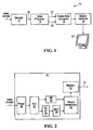
- FIG. 3 is a simplified schematic block diagram of a video processor forming part of the device of FIG. 1 ;
- FIG. 4 is a simplified schematic block diagram of a frame rate converter forming part of the device of FIG. 1 ;
- FIG. 5 schematically illustrates frames in frame rate converted output; decoded/processed output; and an original video source;
- FIG. 6 is a motion graph illustrating motion in a frame rate converted video output from a decoded frame sequence, exhibiting a 3:2 pull-down pattern
- FIG. 1 is a schematic block diagram of video receiver 10, exemplary of an embodiment of the present invention.
- video receiver 10 includes a video decoder 12, a video processor 14, a frame rate converter (FRC) 16, and a display interface 18.
- Video receiver 10 may take the form of a set top box, satellite receiver, terrestrial broadcast receiver, media player (e.g. DVD player), media receiver, or the like.
- Receiver 10 (or portions thereof) may optionally be integrated in a display device, such as a flat panel television, computer monitor, portable television, hand-held device (such as a personal digitial assistant, mobile telephone, video player), or the like.
- Receiver 10 may be formed in custom hardware, or a combination of custom hardware and general purpose computing hardware under software control.
- video receiver 10 receives video, in the form of a video broadcast, digital video stream or the like.
- Decoder 12 in turn decodes the received video to form video fields or frames.
- Video processor 14 processes the decoded fields or frames, to scale, de-interlace, and otherwise manipulate the received video.
- FRC 16 converts the frame rate of processed video in order to generate video at a desired frame rate, different from that of the decoded video. Resulting higher rate frames are presented by display interface 18 on a display 20, for viewing. Display interface 18 may sample or receive frame video generated by FRC 16 to present images for display.
- Display interface 18 may, for example, take the form of a conventional random access memory digital to analog converter (RAMDAC), a single ended or differential transmitter conforming to the HDMI or DVI standard, or any other suitable interface that converts data for display in analog or digital form on display 20 .
- RAMDAC random access memory digital to analog converter
- DVI standard any other suitable interface that converts data for display in analog or digital form on display 20 .
- video attribute information suitable for use by FRC 16 in performing frame rate conversion of the received video may be extracted.
- the attribute information is passed downstream, from video processor 14 to FRC 16 .
- two separate channels 22, 24 may be used to pass video data and attribute data from video processor 14 to FRC 16 .
- FRC 16 uses the received attribute data, and need not analyse decoded video frames to obtain (e.g. extract, determine, calculate, etc.) identical or similar attribute information.
- video decoder 12 decodes a received video signal into a stream of pixel values.
- the video signal arriving at video decoder 12 may originate with any conventional source, such as a satellite, or cable television channel, terrestrial broadcast channel, local video archive or peripheral device such as a DVD player.
- the video signal may be analog or digital.
- Decoder 12 may thus take the form of a conventional video decoder, compliant with any one of a number of video encoding/compression standards, such as MPEG, MPEG 2, MPEG 4, divX, ITU Recommendation ITU-H.264, HDMI, ATSC, PAL or NTSC television, digital television (e.g. ITU BT.601) or the like.
- an example video decoder 12 is exemplified in FIG. 2 , as an MPEG compliant decoder, and as such includes a parser 30 for parsing the received video stream, a variable length decoder (VLD) 32 , a motion compensation block (MB) 34 , a run length decoder and inverse quantization (RL & IQ) block 36 , an inverse discrete cosine transform block (IDCT) 38 , a picture reconstruction block 40 and memory 42 for storing frames/fields, as found in conventional MPEG decoders and known to those of ordinary skill.
- Decoder 12 is in communication with video processor 14 by way of link 26 .
- Link 26 may be a serial or parallel link.
- video processor 14 includes at least one buffer in memory 58 to buffer pixel values received from video decoder 12 .
- Exemplary video processor 14 includes several functional blocks to process video. Each functional block may perform a single function
- Example video processor 14 includes a scaler 50 , a de-interlacer 52 , a color space converter 54 , an effects/overlay engine 56 , and a noise reduction block 48 .
- a person of ordinary will readily appreciate that video processor 14 could include additional functional blocks not specifically illustrated.
- An internal bus 60 interconnects scaler 50 , de-interlacer 52 , color space converter 54 , an effects/overlay engine 56 , and memory 58 .
- An attribute formatter 62 is further in communication with the remaining functional blocks of video processor 14 . Attribute formatter 62 , receives video attribute information from scaler 50 , de-interlacer 52 , color converter 54 , and effects/overlay engine 56 , and noise reducer 48 . A further channel encoder 64 may further format attribute data as formatted by attribute formatter 62 , for transmission on channel 24 to FRC 16 ( FIG. 1 ) .
- example FRC 16 is more particularly depicted in FIG. 4 .
- example FRC 16 includes a buffer 66 , an interpolator 70 that interpolates frames within buffer 66 in order to allow for frame-rate conversion.
- Buffer 66 may be first in, first out frame buffer used to store sequential frames that may be combined by interpolator 70 .
- Buffer 66 may for example store four sequential frames F, for interpolation.
- Frame rate converter 16 further includes a channel decoder 74 and attribute decoder 68 , complementary to channel encoder 64 and attribute encoder 62 .
- Interpolator 70 functions to interpolate frames in buffer 66 , to form output frames at a frame rate (frequency) equal to the frequency of arriving frames at buffer 66 , multiplied by a scaling factor SCALE_FREQU.
- a clock signal (CLK) times the arrival of the frames, and allows FRC 16 to derive the resulting frame rate.
- interpolator 70 functions to form interpolated frames, representative of motion between frames buffered in buffer 66 .
- Such motion compensated interpolation is performed by frame rate converter 16 , from two input frames in buffers 66 .
- interpolator 70 Motion compensation/interpolation techniques that may be performed by interpolator 70 are generally discussed in Keith Jack, Video, 2005, Demystified (A handbook for the Digital Engineer), 4th ed ., and Watkinson, John, The Engineer's Guide to Standards Conversion, Snell and Wilcox Handbook Series (http://www.snellwilcox.com/communitylknowledge center/egineering/estanda rd.pdf ) [0036]
- buffered frames e.g. decoded frames output by video processor 14
- a 24 fps source may have source frames S 0 , S 1 , S 2 , S 3 ....
- Output frames, with converted frame rate in turn will be referred as frames f 0 , f 1 , f 2 .... f n , and may be formed from frames F 0 , F 1 , ...., as detailed herein. This is schematically illustrated in FIG. 5 .
- Interpolated frames are also denoted as I ⁇ S j , S j+1, I/m ⁇ , herein. This notation signifies a resulting motion interpolated frame that represents an intermediate frame between the original frames S j , S j+1, interpolated to represent fractional I/m motion from S j to S j+1 .
- an interpolated frame I ⁇ S j , S j+1 , 1/2 ⁇ is a frame formed to represent motion halfway between S j and S j+1 .
- Such motion interpolation is performed by frame rate converter 16 , from two input frames in buffers 66 .
- FIG. 6 is a graph depicting decoded/processed video frames and frame rate converted frames. Decoded/processed video frames are indicated along the dotted line; interpolated video frames are indicated along the solid line. Decoded/processed video frames are represented by a circle, while interpolated frames are represented as triangles.
- interpolator 70 causes motion in each interpolated frames to advance in fractional fifths of the source frames; in the presence of 2:2 pull-down, in fractional fourths; and in the presence of no pull-down in fractional halves.
- FIG. 6 illustrates motion in an example frame sequence, as output by video processor 14 . More specifically, FIG. 6 illustrates the motion of an example frame sequence, F 0 , F 1 , F 2 , F 3 ... output by video processor 14 .
- the depicted frame sequence originates with a 3:2 pull-down source, typically resulting from a conversion of 24 frames per second (denoted as source frames S 0 , S 1 , S 2 , S 3.. ) to 60 interlaced fields per second, converted to 60 fps frames.
- each second frame in the original (cinema) source is sampled twice, while every other second frame in the original source is sampled three times.
- Resulting frames F 0 , F 1 , F 2 , F 3 exhibit the 3:2 pull-down pattern as they are formed by de-interiacing the interlaced fields.
- the resulting frame sequence exhibits jerky motion (referred to as "judder"), with motion only after the 3 rd , 5 th , 8 th , 10 th , etc. decoded frame.
- This judder remains after frame rate conversion that does not account for the cadence of the video source.
- frame rate converter 16 interpolates adjacent source frames, in order to form a rate converted frame sequence.
- a video stream is received by video decoder 12 , video decoder 12 , in turn, parses the stream and forms a series of fields or frames, having a particular resolution.
- the series of fields or frames is provided as a pixel stream to video processor 14 .
- the format of the decoded video is typically dictated by format of the encoded video. For example, horizontal, vertical resolution; aspect ratio; color format; and whether or not the video is provided as frames or field, for example, is dictated by the video's encoding.
- scaler 50 At video processor 14 , scaler 50 , deinterlacer 52 , color converter 54 , and overlay engine 56 , operate in conventional manners to provide frames of output video. In so processing the video, scaler 50 , deinterlacer 52 , color converter 54 and overlay engine 56, extract and/or create video attribute data.
- the order of operation of scaler 50, deinterlacer 52, color converter 54, and overlay engine 56 is not significant, and may be varied based on design objectives.
- scaler 50 may scale the decoded video to a desired size and aspect ratio. To do so, scaler 50 may optionally otherwise analyze the received frame to assess whether or not any regions of the received video contains black bars, the frequency content of the video, and the like. This attribute may be further used by scaler 50 to scale the decoded video.
- the frequency content of the decoded frame could be provided as data representing a histogram; the beginning and end line and/or column of a matted (e.g. letter box) video image could be provided.
- Attribute data, including that received from decoder 12 , and that formed by scaler 50 may also be passed downstream to attribute formatter 62.
- de-interlacer 52 may be used to convert interlaced fields of video to frames by first analyzing the sequence of received video fields to determine their cadence as for example detailed in U.S. Patent application nos. 10/837,835 and 11/381,254 . Using this cadence information, received fields may be combined by de-interlacer to form de-interlaced frames of video. Video fields may, for example, be bobbed and weaved to form frames. As one frame of video is formed for each two fields, the cadence of the frame sequence will continue to reflect the cadence of the field sequence. Cadence information, as detected by de-interlacer 52 is provided to attribute formatter 62 .
- the cadence information may, for example, include several bits identifying the cadence as determined by de-interlacer 52 .
- Example detected cadence may include the 3:2 pull-down pattern; 2:2 pull-down pattern; 3:3 pull-down pattern, or the like.
- the absence of cadence i.e. no cadence
- a scene change could be signalled by de-interlacer to attribute formatter 62 .
- Color space converter 54 likewise may convert the color space of the received video fields/frames to a desired color space. Data representing the resulting color space may also be passed downstream to attribute formatter 62 . Similar, data representing an indicator of luma or gamma in the video and the like, (e.g. as a histogram of luma distribution, gamma information, and the like) could be signaled by color space converter 54 to attribute formatter 62 .
- Overlay/effects engine 56 may format the received video fields/frames to present the video in a particular format, as for example, picture-in-picture; picture-on-picture; or in conjunction with static images (e.g. TV guide, or the like).
- Attribute formatter 62 may receive the co-ordinates of each picture; context information, describing the nature of each overlay (e.g. computer generated, video, static, images, etc.) from overlay/effects engine 56 .
- Noise reduction block 48 may filter the received video to remove noise and/or artifacts.
- Attribute formatter 62 may receive information about the noise level, signal type, signal level and the like from noise reduction block 48 .
- attribute formatter 62 receives video attributes from the remaining functional blocks, such as scaler 50 , de-interlacer 52 , color converter 54 , overlay engine 56 , and noise reduction block 48 . Attribute formatter 62 may format these in a suitable format so that these may be encoded on channel 24 and explicitly passed downstream to FRC 16 .
- Attribute formatter 62 formats the attribute data in a suitable format to accompany video frames generated by processor 14 .
- attribute formatter 62 may encode attributes about that frame, and packetize this information.
- the actual format of each packet is somewhat arbitrary.
- the packet may take the form of bits, or bytes representing attribute information.
- the packet could alternatively contain text data identifying the attributes of interest, or could be formatted using a formatting language such as XML.
- Attribute formatter 62 may alternatively format attribute data in accordance with ITU Recommendation ITU-BT.1364-1, or in other ways understood by those of ordinary skill.
- attribute data as formatted by attribute formatter 62 is passed downstream to channel encoder 64 .
- Channel encoder 64 encodes the attribute data in an auxiliary channel in such a way that the encoded data remains synchronized with frames output by video processor 14 .
- the auxiliary channel may take any form.
- attribute data may be passed along a dedicated channel that may be provided by way of separate physical link, or that may be multiplexed with video or other data.
- One or more packets of attribute data may be generated with each frame.
- Channel encoder 64 include a multiplexer, and may format the attribute channel and multiplex it with video data to occupy unused portions of the video data (e.g. vertical blank or horizontal blank intervals), or the like.
- channel encoder 64 could encode a separate physical channel that could carry data that is in some way synchronized to the video data.
- the channel could be a synchronous stream, or an asynchronous carrying a packet transmitted with each frame.
- video data from video processor 14 is buffered in buffer 66, and attribute data is extracted from the attribute channel by channel decoder 74 , and attribute extractor 68 .
- Resulting attribute information may be provided to interpolator 70 , and optionally to cadence detector 72 .
- cadence detector 72 may be disabled, or cadence data generated by it may be ignored. Otherwise, if the auxiliary data does not include cadence information about the video, cadence detector 72 may determine cadence information from frames buffered in buffer 66 . Cadence information determined by detector 72 may only be determined after a particular frame has been buffered, and may thus lag the cadence information available from video processor 14 , by one frame.
- attribute data extracted by attribute decoder 68 may be used by FRC 16 to adjust operating parameters of FRC 16 , to improve interpolation.
- overlay context attribute data may be used by FRC to independently process overlay regions.
- Luma information could be used to pre-filter the interpolated frames (e.g. scenes could be filtered differently based on their darkness).
- Gamma information could be used to do de-gamma first and then re-gamma.
- Frequency information about the video could be used to adjust or select filters of FRC 16 , and its sensitivity. Information reflecting the type of noise and signal level could similarly be-used to adjust filters and sensitivity of FRC 16 .
- Other uses of attribute data by FRC 16 will be readily apparent to those of ordinary skill.
- FRC 16 is provided with an identifier of the pull-down pattern by video processor 14 to perform interpolation, in order to produce motion compensated, interpolated frames from the original source frames.
- the cadence indicator may be used to interpolate different (as opposed to repeated) frames in the source, and to adjust interpolation parameters (e.g. desired fractional motion from interpolated frame to interpolated frame).
- FIG. 6 illustrates motion in a desired output frame sequence f 0 , f 1 , f 2 , f 3 ... output by frame rate converter 16 , from a frame sequence F 0 , F 1 , F 2 ....
- motion is depicted as a function of frame number.
- interpolator 70 FIG. 2 ) of frame rate converter 16 uses conventional motion compensation techniques in order to produce frames for presentation at the higher rate.
- each interpolated frame f j is either identical to a frame F i output by video processor 14 , or formed from two adjacent source frames in the decoded frame sequence (e.g. S i , S i+1 ). Of course, more than two adjacent source frames could be used in producing interpolated frames.
- motion compensation is performed to produce relatively smooth motion, and to reduce judder.
- motion is linearly interpolated, with equal motion between each of frames f 0 , f 1 , f 2 , f 3 , and so on.
- any linearly interpolated sequence f 0 , f 1 , f 2 , f 3 ... will typically not include frames corresponding to frames S 0 , S 1 , ... in the source, at the same times as these are decoded by video processor 14 .
- f 0 F 1
- f 1 , f 2 , f 3 , and f 4 are derived from an interpolation of F 0 (or equivalent frames F, or F 2 ) and F 3 (i.e. source frame S 0 and S 1 ).
- Each interpolated frame f 1 , f 2 , f 3 , and f 4 advances motion from F 0 to F 3 (i.e. from frame S 0 to frame S 1 of the original source).
- Output frame f 5 is original source frame S 1 (i.e. frame F 3 /F 4 ).
- Output frame f 6 , and f 7 are similarly derived from decoder frames F 3 /F 4 and F 5 (corresponding to source frames S 1 and S 2 ).
- FRC 16 In the presence of a 3:2 pull-down pattern, FRC 16 relies on buffered frames that are up to three frames apart (i.e. F 0 and F 3 ; F 3 and F 5 ), FRC 16 will introduce a processing delay of at least this many frames. Thus f 1 is produced no earlier than after decoding of F 3 . Similarly, f 6 is produced no earlier than after decoding F 5 ; and f 11 is produced no earlier than after decoding F 8 .
- f 10 correspond to S 0 , I ⁇ S 0 ,S 1 ,1/5 ⁇ , I ⁇ S 0 ,S 1 ,2/5 ⁇ , I ⁇ S 0 ,S 1 ,3/5 ⁇ ,I ⁇ S 0 ,S 1 ,4/5 ⁇ , S 1 , I ⁇ S 1 ,S 2 ,1/5), I ⁇ S 1 ,S 2 ,2/5 ⁇ , I ⁇ S 1 ,S 2 ,3/5 ⁇ , I ⁇ S 1 ,S 2 ,4/5 ⁇ , S 2 .
- the resulting frame pattern f 0 , f 1 , f 2 , f 3 ... f 10 for a 2:2 pull-down source would correspond to frames S 0 , I ⁇ S 0 , S 1 ,1/4 ⁇ , I ⁇ S 0, S 1 ,1/2 ⁇ , I ⁇ S 0 ,S 1 ,3/4 ⁇ , S 1 , I ⁇ S 1 ,S 2 ,1/4 ⁇ , I ⁇ S 1 ,S 2 ,1/2 ⁇ , I ⁇ S 1 ,S 2 ,3/4 ⁇ , S 2 , I ⁇ S 2 ,S 3 ,1/4 ⁇ , I ⁇ S 2 ,S 3 ,1/2 ⁇ .... That is, four output frames are produced for every buffered frame.
- the resulting frame pattern for no pull-down pattern (e.g. resulting from interlaced video) would corresponds to frames S 0 , I ⁇ S 0 ,S 1 , 1/2 ⁇ , S 1 , ⁇ S 1 ,S 2 , 1/2 ⁇ ,S 2 , ⁇ S 2 ,S 3 ,1/2 ⁇ ...
- Two output frames are produced for every buffered frame.
- attribute data is available with processed frames, as received by video processor 14 .
- FRC 16 may react quickly to the provided attribute data. For example, as the cadence of the video provided by video processor 14 changes, interpolation parameters used by FRC 16 may be adjusted. Thus, as soon as a change from a recognized pull-down pattern to no cadence is detected, interpolation may proceed to form interpolated frames corresponding to source frames S 0 , I ⁇ S 0 ,S 1 , 1/2 ⁇ , S 1 , ⁇ S 1 ,S 2 , 1/2 ⁇ ,S 2 , ⁇ S 2 ,S 3 , 1/2 ⁇ ...
- attribute data is available with video data, latency required by analysis may be reduced.
- attribute data provided to FRC 16 need not originate with video processor 14 . Instead, attribute data could originate elsewhere upstream of FRC 14 .
- additional attribute data or some of the attribute data described could be obtained by decoder 12 .
- motion vector data could be extracted by any MPEG or similar decoder used to form decoder 12 ; the source and/or type of decoded video (CVBS, component, digital, progressive, interlaced, VGA) could be passed as attribute data.
- CVBS source and/or type of decoded video
- a video received need not include decoder 12 .
- decoded video from an external source could be provided to a video device exemplary of an embodiment of the present invention, including only video processor 14, frame rate converter 16, and optional display interface 18.
- video processor 14 and FRC 16 could be formed in different physical devices.
- video processor 14 could form part of a video receiver, video player, dedicated video processor or the like
- FRC 16 could form part of a display device, such as a flat panel display.
- the link between video processor 14 and FRC 16 could then be a physical link, complying with a video interconnect standard, such as the DVI or HDMI standard.
- Channels 22 and 24 may then be channels carried by the interconnect.
- channels 22 and 24 could be carried on an HDMI interconnect.
- attribute data has been described as being provided synchronously, it may also be buffered at video processor 14, and may be extracted or pulled from video processor 14, by FRC 16 or some other processor (such as a host processor).
- Video processor 14 may accordingly include sufficient storage memory for storing attribute data and provide a suitable interface (such as a software application programmer interface (API)) for querying the data.
- a suitable interface such as a software application programmer interface (API)
- video processor 14 may buffer the attribute data for several frames. The attribute data may then be queried as required.
Landscapes
- Engineering & Computer Science (AREA)
- Multimedia (AREA)
- Signal Processing (AREA)
- Television Systems (AREA)
- Two-Way Televisions, Distribution Of Moving Picture Or The Like (AREA)
Claims (9)
- Verfahren zum Herstellen von bildfrequenzumgewandeltem Video, das umfasst:a. Verarbeiten von empfangenem Video, um Daten herzustellen, die Videobilder repräsentieren;b. Erhalten von Attributdaten von dem empfangenen Video;c. Weiterleiten der Daten, die Videobilder repräsentieren, an einen Bildfrequenzumwandler;d. Weiterleiten der Attributdaten in einem Hilfskanal an einen Bildfrequenzumwandler;e. Empfangen der Daten, die Videobilder repräsentieren;f. Empfangen der Attributdaten auf dem Hilfskanal;g. Herstellen von bildfrequenzumgewandeltem Video durch einen Bildfrequenzumwandler aus den Daten, die Videobilder repräsentieren, basierend auf den Attributdaten, die wenigstens Kadenzinformations-Attributdaten enthalten, die von dem empfangenen Video während der Verarbeitung erhalten wurden;dadurch gekennzeichnet, dass das Herstellen von bildfrequenzumgewandeltem Video umfasst:Interpolieren von Bildern, um interpolierte Bilder aus den Daten zu erzeugen, die Videobilder repräsentieren, unter Verwendung der Kadenzinformations-Attributdaten, um einen gewünschten fraktionalen linearen zeitlichen Fortgang von einem interpolierten Bild zu einem nächsten interpolierten Bild der interpolierten Bilder einzustellen.
- Verfahren nach Anspruch 1, wobei das Verarbeiten das Zeilenentflechten (Deinterlacing) des empfangenen Videos umfasst, um die Bilder herzustellen.
- Verfahren nach Anspruch 2, wobei das Zeilenentflechten das Bestimmen einer Kadenz des empfangenen Videos umfasst, und wobei die Attributdaten Kadenzinformationen aufweisen.
- Verfahren nach Anspruch 1, wobei der Hilfskanal mit den Daten, die Videobilder repräsentieren, gemultiplext wird.
- Videoprozessor (14) mit:a. einer Vielzahl von Videoverarbeitungsblöcken (50, 52, 56, 54, 58), die jeweils zum Durchführen wenigstens einer Videoverarbeitungsfunktion für empfangenes Video vorgesehen sind, um Videobilder zur Lieferung an einen Bildfrequenzwandler (16) herzustellen, wobei jeder der Videoverarbeitungsblöcke (50, 52, 56, 54, 58) betreibbar ist, um Attributinformationen über das empfangene Video zu erhalten;b. einen Attributformatierer (62) zum Empfangen der Attributinformationen von den Videoverarbeitungsblöcken (50, 52, 56, 54, 58) und zum Herstellen von Attributdaten daraus;c. einen Kanalcodierer (64) zum Codieren der Attributdaten auf einem Kanal zu dem Bildfrequenzwandler (16);wobei die Attributdaten wenigstens Kadenzinformations-Attributdaten enthalten, die von dem empfangenen Video während der wenigstens einen Videoverarbeitungsfunktion erhalten wurden;
dadurch gekennzeichnet, dass die Kadenzinformations-Attributdaten konfiguriert sind, um von dem Bildfrequenzwandler (16) verwendet zu werden, um einen gewünschten fraktionalen linearen zeitlichen Fortgang von einem interpolierten Bild zu einem nächsten interpolierten Bild bei einer Generation interpolierter Bilder aus den Videobildern einzustellen. - Videoempfänger (10) mit:a. dem Videoprozessor (14) von Anspruch 5, der einen Zeilenentflechter (52) zum Zeilenentflechten empfangener Videofelder aufweist, um Videobilder zum Liefern an den Bildfrequenzwandler (16) herzustellen, wobei der Zeilenentflechter (52) betreibbar ist, um eine Kadenz der empfangenen Videofelder zu ermitteln;b. dem Attributformatierer (62) zum Empfangen einer Anzeige der Kadenz und zum Herstellen der Attributdaten daraus.
- Videoempfänger (10) nach Anspruch 6, wobei der Kanalcodierer (64) einen Multiplexer zum Multiplexen der Videobilder und der Attributdaten aufweist.
- Bildfrequenzwandler (16) mit:a. einem Kanaldecodierer (74) zum Decodieren von Attributdaten über Videobilder, die an den Bildfrequenzwandler (16) geliefert wurden;b. einen Interpolator (70) zum Herstellen von bildfrequenzumgewandeltem Video aus Daten, die Videobilder repräsentieren, basierend auf den Attributdaten, die wenigstens Kadenzinformations-Attributdaten enthalten;dadurch gekennzeichnet, dass der Bildfrequenzwandler (16) konfiguriert ist, um die Kadenzinformations-Attributdaten zu verwenden, um einen gewünschten fraktionalen linearen zeitlichen Fortgang von einem interpolierten Bild zu einem nächsten interpolierten Bild bei einer Generation interpolierter Bilder aus den Videobildern durch den Interpolator (70) einzustellen.
- Videoanzeigegerät (20) mit dem Bildfrequenzwandler (16) von Anspruch 8.
Applications Claiming Priority (2)
| Application Number | Priority Date | Filing Date | Title |
|---|---|---|---|
| US11/616,188 US8134640B2 (en) | 2006-12-26 | 2006-12-26 | Video processor architecture and method for frame rate conversion |
| PCT/US2007/088813 WO2008083151A1 (en) | 2006-12-26 | 2007-12-26 | Video processor architecture and method for frame rate conversion |
Publications (2)
| Publication Number | Publication Date |
|---|---|
| EP2127371A1 EP2127371A1 (de) | 2009-12-02 |
| EP2127371B1 true EP2127371B1 (de) | 2012-08-15 |
Family
ID=39469610
Family Applications (1)
| Application Number | Title | Priority Date | Filing Date |
|---|---|---|---|
| EP07869897A Active EP2127371B1 (de) | 2006-12-26 | 2007-12-26 | Videoprozessorarchitektur und verfahren für bildfrequenzumwandlung |
Country Status (4)
| Country | Link |
|---|---|
| US (1) | US8134640B2 (de) |
| EP (1) | EP2127371B1 (de) |
| CN (1) | CN101641952B (de) |
| WO (1) | WO2008083151A1 (de) |
Families Citing this family (28)
| Publication number | Priority date | Publication date | Assignee | Title |
|---|---|---|---|---|
| US8284322B2 (en) | 2006-04-18 | 2012-10-09 | Marvell World Trade Ltd. | Shared memory multi video channel display apparatus and methods |
| US8218091B2 (en) | 2006-04-18 | 2012-07-10 | Marvell World Trade Ltd. | Shared memory multi video channel display apparatus and methods |
| US8264610B2 (en) * | 2006-04-18 | 2012-09-11 | Marvell World Trade Ltd. | Shared memory multi video channel display apparatus and methods |
| JP5208381B2 (ja) * | 2006-06-30 | 2013-06-12 | 株式会社東芝 | 動画像フレームレート変換装置および動画像フレームレート変換方法 |
| KR101197149B1 (ko) * | 2007-07-10 | 2012-11-08 | 삼성전자주식회사 | 디스플레이장치 및 그 제어방법 |
| US8300958B2 (en) * | 2007-07-11 | 2012-10-30 | Samsung Electronics Co., Ltd. | System and method for detecting scrolling text in mixed mode film and video |
| JP4831081B2 (ja) * | 2008-01-22 | 2011-12-07 | ソニー株式会社 | 送信装置及びフレームレート変換システム |
| JP4296218B1 (ja) * | 2008-02-21 | 2009-07-15 | シャープ株式会社 | 映像表示装置 |
| US8368809B2 (en) * | 2008-03-18 | 2013-02-05 | Zoran (France) | Frame rate conversion with motion estimation in a plurality of resolution levels |
| KR101286541B1 (ko) * | 2008-05-19 | 2013-07-23 | 엘지디스플레이 주식회사 | 액정표시장치 |
| US8374240B1 (en) * | 2008-07-10 | 2013-02-12 | Marvell International Ltd. | Image frame management |
| US8094234B2 (en) * | 2008-10-14 | 2012-01-10 | Texas Instruments Incorporated | System and method for multistage frame rate conversion |
| US20100111181A1 (en) * | 2008-11-06 | 2010-05-06 | Mediatek Inc. | Video processing apparatus and methods |
| TWI500329B (zh) * | 2009-01-23 | 2015-09-11 | Realtek Semiconductor Corp | 去交錯之視訊處理裝置及其相關方法 |
| EP2415259B1 (de) * | 2009-04-01 | 2015-09-16 | Marvell World Trade Ltd. | Erkennung von kadenzen in progressiv-videoinhalten |
| US8643776B2 (en) * | 2009-11-30 | 2014-02-04 | Mediatek Inc. | Video processing method capable of performing predetermined data processing operation upon output of frame rate conversion with reduced storage device bandwidth usage and related video processing apparatus thereof |
| US20110280312A1 (en) * | 2010-05-13 | 2011-11-17 | Texas Instruments Incorporated | Video processing device with memory optimization in image post-processing |
| CN102685437B (zh) * | 2012-02-03 | 2016-06-29 | 深圳市创维群欣安防科技股份有限公司 | 视频图像补偿方法及监视器 |
| JP6210772B2 (ja) * | 2013-07-22 | 2017-10-11 | キヤノン株式会社 | 情報処理装置、撮像装置、制御方法、及びプログラム |
| CN103702059B (zh) * | 2013-12-06 | 2018-01-30 | 乐视致新电子科技(天津)有限公司 | 一种帧率转换控制方法及装置 |
| US9967581B2 (en) | 2014-05-29 | 2018-05-08 | Apple Inc. | Video quality adaptation with frame rate conversion |
| US20160182853A1 (en) * | 2015-03-20 | 2016-06-23 | Mediatek Inc. | Dynamic Content Adaptive Frame Rate Conversion |
| US9959599B2 (en) * | 2015-06-18 | 2018-05-01 | Sharp Laboratories Of America, Inc. | System for enhanced images |
| CN105739670B (zh) * | 2016-02-01 | 2019-02-05 | Oppo广东移动通信有限公司 | 用于移动终端的显示方法、装置和移动终端 |
| US10200732B1 (en) | 2016-11-03 | 2019-02-05 | Amazon Technologies, Inc. | Output-aligned avail blanking for video streams |
| TWI664852B (zh) * | 2018-03-19 | 2019-07-01 | 瑞昱半導體股份有限公司 | 影像處理裝置及影像處理方法 |
| TWI808970B (zh) | 2018-04-30 | 2023-07-21 | 圓剛科技股份有限公司 | 影像訊號轉換裝置 |
| TWI805581B (zh) * | 2018-04-30 | 2023-06-21 | 圓剛科技股份有限公司 | 影像訊號轉換裝置 |
Citations (1)
| Publication number | Priority date | Publication date | Assignee | Title |
|---|---|---|---|---|
| US20060078293A1 (en) * | 2004-10-08 | 2006-04-13 | Wyman Richard H | Method and system for trick mode support in a motion adaptive deinterlacer with inverse telecine |
Family Cites Families (21)
| Publication number | Priority date | Publication date | Assignee | Title |
|---|---|---|---|---|
| US6957350B1 (en) * | 1996-01-30 | 2005-10-18 | Dolby Laboratories Licensing Corporation | Encrypted and watermarked temporal and resolution layering in advanced television |
| US5936676A (en) | 1997-08-21 | 1999-08-10 | Miranda Technologies Inc. | Apparatus and method for line interpolating an interlaced video signal |
| US6549577B2 (en) * | 1997-09-26 | 2003-04-15 | Sarnoff Corporation | Computational resource allocation in an information stream decoder |
| US6111610A (en) * | 1997-12-11 | 2000-08-29 | Faroudja Laboratories, Inc. | Displaying film-originated video on high frame rate monitors without motions discontinuities |
| US6782132B1 (en) * | 1998-08-12 | 2004-08-24 | Pixonics, Inc. | Video coding and reconstruction apparatus and methods |
| US6466624B1 (en) * | 1998-10-28 | 2002-10-15 | Pixonics, Llc | Video decoder with bit stream based enhancements |
| US6658056B1 (en) * | 1999-03-30 | 2003-12-02 | Sony Corporation | Digital video decoding, buffering and frame-rate converting method and apparatus |
| AUPQ377899A0 (en) * | 1999-10-29 | 1999-11-25 | Canon Kabushiki Kaisha | Phase three kernel selection |
| US7164431B1 (en) * | 2001-05-08 | 2007-01-16 | Pixelworks, Inc. | System and method for mixing graphics and text in an on-screen display application |
| JP4458714B2 (ja) * | 2001-06-20 | 2010-04-28 | 富士通マイクロエレクトロニクス株式会社 | 画像復号装置、画像復号方法、および、プログラム |
| KR20040015965A (ko) * | 2002-08-14 | 2004-02-21 | 엘지전자 주식회사 | 포맷 변환 장치 |
| JP4315731B2 (ja) * | 2003-05-16 | 2009-08-19 | 株式会社ルネサステクノロジ | 画像復号表示装置 |
| US7075581B1 (en) | 2003-06-03 | 2006-07-11 | Zoran Corporation | Interlaced-to-progressive scan conversion based on film source detection |
| US7557861B2 (en) * | 2004-01-30 | 2009-07-07 | Broadcom Corporation | Reverse pull-down video using corrective techniques |
| US7529426B2 (en) | 2004-01-30 | 2009-05-05 | Broadcom Corporation | Correlation function for signal detection, match filters, and 3:2 pulldown detection |
| US7738045B2 (en) | 2004-05-03 | 2010-06-15 | Broadcom Corporation | Film-mode (3:2/2:2 Pulldown) detector, method and video device |
| JP4396496B2 (ja) | 2004-12-02 | 2010-01-13 | 株式会社日立製作所 | フレームレート変換装置、及び映像表示装置、並びにフレームレート変換方法 |
| US7349029B1 (en) * | 2005-01-19 | 2008-03-25 | Kolorific, Inc. | Method and apparatus for de-interlacing interlaced video fields originating from a progressive video source |
| US8027382B2 (en) | 2006-06-27 | 2011-09-27 | Apple Inc. | Pulldown correction for progressive display of audiovisual recordings |
| US7961256B2 (en) * | 2006-10-17 | 2011-06-14 | Broadcom Corporation | System and method for bad weave detection for inverse telecine |
| US8233087B2 (en) | 2006-11-08 | 2012-07-31 | Marvell International Ltd. | Systems and methods for deinterlacing high-definition and standard-definition video |
-
2006
- 2006-12-26 US US11/616,188 patent/US8134640B2/en not_active Expired - Fee Related
-
2007
- 2007-12-26 WO PCT/US2007/088813 patent/WO2008083151A1/en not_active Ceased
- 2007-12-26 EP EP07869897A patent/EP2127371B1/de active Active
- 2007-12-26 CN CN2007800433222A patent/CN101641952B/zh not_active Expired - Fee Related
Patent Citations (1)
| Publication number | Priority date | Publication date | Assignee | Title |
|---|---|---|---|---|
| US20060078293A1 (en) * | 2004-10-08 | 2006-04-13 | Wyman Richard H | Method and system for trick mode support in a motion adaptive deinterlacer with inverse telecine |
Also Published As
| Publication number | Publication date |
|---|---|
| WO2008083151A1 (en) | 2008-07-10 |
| EP2127371A1 (de) | 2009-12-02 |
| CN101641952A (zh) | 2010-02-03 |
| US8134640B2 (en) | 2012-03-13 |
| CN101641952B (zh) | 2013-07-10 |
| US20080151108A1 (en) | 2008-06-26 |
Similar Documents
| Publication | Publication Date | Title |
|---|---|---|
| EP2127371B1 (de) | Videoprozessorarchitektur und verfahren für bildfrequenzumwandlung | |
| KR101554685B1 (ko) | 비디오 프로세싱을 기술하기 위한 방법, 장치 및 머신 판독가능 매체 | |
| US8693552B2 (en) | Low latency cadence detection for frame rate conversion | |
| JP4266389B2 (ja) | フィルムでないソースの高品質の再生のための動き信号を用いる汎用ビデオディスク記録および再生 | |
| AU755005B2 (en) | Receiver for simultaneously displaying signals having different display formats and/or different frame rates and method thereof | |
| US20110001873A1 (en) | Frame rate converter for input frames with video and film content | |
| US6256045B1 (en) | Device and method for processing picture in MPEG decoder | |
| US7880808B2 (en) | Video signal processing apparatus to generate both progressive and interlace video signals | |
| EP1434438A2 (de) | Vorrichtung und Verfahren zur Erkennung des Bildsignalformats | |
| US20050094030A1 (en) | Method and/or circuitry for video frame rate and/or size conversion | |
| US20050025462A1 (en) | Method and apparatus for equipping personal digital product with functions of recording and displaying of the digital video/audio multi-media | |
| US20050088573A1 (en) | Unified system for progressive and interlaced video transmission | |
| CN100405819C (zh) | 逐行扫描和隔行信号之间的检测和选择 | |
| KR100378788B1 (ko) | 다중-표준형2화면영상신호처리회로 | |
| KR20010002438A (ko) | 선택 디코딩 및 다중 디스플레이를 위한 디지털 티브이 수신시스템 및 방법 | |
| JP2000165742A (ja) | 映像信号処理装置 | |
| KR20020015862A (ko) | 비디오 포맷 변환장치 및 방법 | |
| US20050007490A1 (en) | Scaling by early deinterlacing | |
| JP2008061067A (ja) | 映像表示システム、再生装置および表示装置 | |
| JP2000341583A (ja) | 映像信号処理装置 | |
| KR20030073653A (ko) | 텔레비전의 주사방식 변환방법 |
Legal Events
| Date | Code | Title | Description |
|---|---|---|---|
| PUAI | Public reference made under article 153(3) epc to a published international application that has entered the european phase |
Free format text: ORIGINAL CODE: 0009012 |
|
| 17P | Request for examination filed |
Effective date: 20090727 |
|
| AK | Designated contracting states |
Kind code of ref document: A1 Designated state(s): DE GB |
|
| DAX | Request for extension of the european patent (deleted) | ||
| 17Q | First examination report despatched |
Effective date: 20100702 |
|
| GRAP | Despatch of communication of intention to grant a patent |
Free format text: ORIGINAL CODE: EPIDOSNIGR1 |
|
| GRAS | Grant fee paid |
Free format text: ORIGINAL CODE: EPIDOSNIGR3 |
|
| GRAA | (expected) grant |
Free format text: ORIGINAL CODE: 0009210 |
|
| AK | Designated contracting states |
Kind code of ref document: B1 Designated state(s): DE GB |
|
| REG | Reference to a national code |
Ref country code: GB Ref legal event code: FG4D |
|
| REG | Reference to a national code |
Ref country code: DE Ref legal event code: R096 Ref document number: 602007024878 Country of ref document: DE Effective date: 20121011 |
|
| PLBE | No opposition filed within time limit |
Free format text: ORIGINAL CODE: 0009261 |
|
| STAA | Information on the status of an ep patent application or granted ep patent |
Free format text: STATUS: NO OPPOSITION FILED WITHIN TIME LIMIT |
|
| 26N | No opposition filed |
Effective date: 20130516 |
|
| REG | Reference to a national code |
Ref country code: DE Ref legal event code: R097 Ref document number: 602007024878 Country of ref document: DE Effective date: 20130516 |
|
| REG | Reference to a national code |
Ref country code: DE Ref legal event code: R082 Ref document number: 602007024878 Country of ref document: DE Representative=s name: BOSCH JEHLE PATENTANWALTSGESELLSCHAFT MBH, DE Ref country code: DE Ref legal event code: R081 Ref document number: 602007024878 Country of ref document: DE Owner name: AVAGO TECHNOLOGIES INTERNATIONAL SALES PTE. LT, SG Free format text: FORMER OWNER: BROADCOM CORPORATION, IRVINE, CALIF., US Ref country code: DE Ref legal event code: R081 Ref document number: 602007024878 Country of ref document: DE Owner name: AVAGO TECHNOLOGIES GENERAL IP (SINGAPORE) PTE., SG Free format text: FORMER OWNER: BROADCOM CORPORATION, IRVINE, CALIF., US |
|
| REG | Reference to a national code |
Ref country code: GB Ref legal event code: 732E Free format text: REGISTERED BETWEEN 20171005 AND 20171011 |
|
| REG | Reference to a national code |
Ref country code: DE Ref legal event code: R082 Ref document number: 602007024878 Country of ref document: DE Representative=s name: BOSCH JEHLE PATENTANWALTSGESELLSCHAFT MBH, DE Ref country code: DE Ref legal event code: R081 Ref document number: 602007024878 Country of ref document: DE Owner name: AVAGO TECHNOLOGIES INTERNATIONAL SALES PTE. LT, SG Free format text: FORMER OWNER: AVAGO TECHNOLOGIES GENERAL IP (SINGAPORE) PTE. LTD., SINGAPORE, SG |
|
| REG | Reference to a national code |
Ref country code: GB Ref legal event code: 732E Free format text: REGISTERED BETWEEN 20190222 AND 20190227 |
|
| PGFP | Annual fee paid to national office [announced via postgrant information from national office to epo] |
Ref country code: GB Payment date: 20231121 Year of fee payment: 17 |
|
| PGFP | Annual fee paid to national office [announced via postgrant information from national office to epo] |
Ref country code: DE Payment date: 20241210 Year of fee payment: 18 |
|
| GBPC | Gb: european patent ceased through non-payment of renewal fee |
Effective date: 20241226 |
|
| PG25 | Lapsed in a contracting state [announced via postgrant information from national office to epo] |
Ref country code: GB Free format text: LAPSE BECAUSE OF NON-PAYMENT OF DUE FEES Effective date: 20241226 |