EP2126947B1 - Druckgasschalter mit einer radialen durchströmöffnung - Google Patents
Druckgasschalter mit einer radialen durchströmöffnung Download PDFInfo
- Publication number
- EP2126947B1 EP2126947B1 EP07857869.7A EP07857869A EP2126947B1 EP 2126947 B1 EP2126947 B1 EP 2126947B1 EP 07857869 A EP07857869 A EP 07857869A EP 2126947 B1 EP2126947 B1 EP 2126947B1
- Authority
- EP
- European Patent Office
- Prior art keywords
- gas
- pressure
- valve
- circuit breaker
- contact
- Prior art date
- Legal status (The legal status is an assumption and is not a legal conclusion. Google has not performed a legal analysis and makes no representation as to the accuracy of the status listed.)
- Active
Links
Images


Classifications
-
- H—ELECTRICITY
- H01—ELECTRIC ELEMENTS
- H01H—ELECTRIC SWITCHES; RELAYS; SELECTORS; EMERGENCY PROTECTIVE DEVICES
- H01H33/00—High-tension or heavy-current switches with arc-extinguishing or arc-preventing means
- H01H33/70—Switches with separate means for directing, obtaining, or increasing flow of arc-extinguishing fluid
- H01H33/88—Switches with separate means for directing, obtaining, or increasing flow of arc-extinguishing fluid the flow of arc-extinguishing fluid being produced or increased by movement of pistons or other pressure-producing parts
- H01H33/90—Switches with separate means for directing, obtaining, or increasing flow of arc-extinguishing fluid the flow of arc-extinguishing fluid being produced or increased by movement of pistons or other pressure-producing parts this movement being effected by or in conjunction with the contact-operating mechanism
- H01H33/901—Switches with separate means for directing, obtaining, or increasing flow of arc-extinguishing fluid the flow of arc-extinguishing fluid being produced or increased by movement of pistons or other pressure-producing parts this movement being effected by or in conjunction with the contact-operating mechanism making use of the energy of the arc or an auxiliary arc
-
- H—ELECTRICITY
- H01—ELECTRIC ELEMENTS
- H01H—ELECTRIC SWITCHES; RELAYS; SELECTORS; EMERGENCY PROTECTIVE DEVICES
- H01H33/00—High-tension or heavy-current switches with arc-extinguishing or arc-preventing means
- H01H33/70—Switches with separate means for directing, obtaining, or increasing flow of arc-extinguishing fluid
- H01H33/88—Switches with separate means for directing, obtaining, or increasing flow of arc-extinguishing fluid the flow of arc-extinguishing fluid being produced or increased by movement of pistons or other pressure-producing parts
- H01H33/90—Switches with separate means for directing, obtaining, or increasing flow of arc-extinguishing fluid the flow of arc-extinguishing fluid being produced or increased by movement of pistons or other pressure-producing parts this movement being effected by or in conjunction with the contact-operating mechanism
- H01H2033/906—Switches with separate means for directing, obtaining, or increasing flow of arc-extinguishing fluid the flow of arc-extinguishing fluid being produced or increased by movement of pistons or other pressure-producing parts this movement being effected by or in conjunction with the contact-operating mechanism with pressure limitation in the compression volume, e.g. by valves or bleeder openings
-
- H—ELECTRICITY
- H01—ELECTRIC ELEMENTS
- H01H—ELECTRIC SWITCHES; RELAYS; SELECTORS; EMERGENCY PROTECTIVE DEVICES
- H01H33/00—High-tension or heavy-current switches with arc-extinguishing or arc-preventing means
- H01H33/70—Switches with separate means for directing, obtaining, or increasing flow of arc-extinguishing fluid
- H01H33/88—Switches with separate means for directing, obtaining, or increasing flow of arc-extinguishing fluid the flow of arc-extinguishing fluid being produced or increased by movement of pistons or other pressure-producing parts
- H01H33/90—Switches with separate means for directing, obtaining, or increasing flow of arc-extinguishing fluid the flow of arc-extinguishing fluid being produced or increased by movement of pistons or other pressure-producing parts this movement being effected by or in conjunction with the contact-operating mechanism
- H01H2033/908—Switches with separate means for directing, obtaining, or increasing flow of arc-extinguishing fluid the flow of arc-extinguishing fluid being produced or increased by movement of pistons or other pressure-producing parts this movement being effected by or in conjunction with the contact-operating mechanism using valves for regulating communication between, e.g. arc space, hot volume, compression volume, surrounding volume
-
- H—ELECTRICITY
- H01—ELECTRIC ELEMENTS
- H01H—ELECTRIC SWITCHES; RELAYS; SELECTORS; EMERGENCY PROTECTIVE DEVICES
- H01H33/00—High-tension or heavy-current switches with arc-extinguishing or arc-preventing means
- H01H33/70—Switches with separate means for directing, obtaining, or increasing flow of arc-extinguishing fluid
- H01H33/88—Switches with separate means for directing, obtaining, or increasing flow of arc-extinguishing fluid the flow of arc-extinguishing fluid being produced or increased by movement of pistons or other pressure-producing parts
- H01H33/90—Switches with separate means for directing, obtaining, or increasing flow of arc-extinguishing fluid the flow of arc-extinguishing fluid being produced or increased by movement of pistons or other pressure-producing parts this movement being effected by or in conjunction with the contact-operating mechanism
- H01H33/91—Switches with separate means for directing, obtaining, or increasing flow of arc-extinguishing fluid the flow of arc-extinguishing fluid being produced or increased by movement of pistons or other pressure-producing parts this movement being effected by or in conjunction with the contact-operating mechanism the arc-extinguishing fluid being air or gas
Definitions
- the invention relates to the field of medium voltage switch and high voltage switch technology, in particular the circuit breaker in power distribution networks. It relates in particular to a compressed gas switch according to the preamble of claim 1 or of claim 5.
- WO 98/43265 such a compressed gas switch.
- This has a first, drivable arcing contact, a second, fixed arcing contact, a rated current path running concentrically therewith and a compression device in order to compress quenching gas in a blowing volume.
- the compressed quenching gas is used to extinguish an arc resulting from the separation of the first arcing contact from the second arcing contact by blowing it with quenching gas.
- the first, drivable arcing contact is carried by a switching tube.
- an exhaust volume is provided, in which the quenching gas is passed after the blowing of the arc.
- the arranged within the nominal flow path exhaust volume communicates with a low pressure space outside the nominal flow path via exhaust ports in combination.
- the exhaust volume is separated by a partition wall of a suction, which is also arranged between blowing volume and exhaust volume within the nominal flow path. This suction is connected via a flush valve as well as a pressure relief valve with the blowing volume. Through the partition, the movable switching tube is passed tightly.
- This known gas pressure switch solves the problem that in the intake should prevail at least a nearly constant gas pressure, so that the gas pressure in the exhaust volume has no effect on the function of the purge valve as well as on the function of the pressure relief valve.
- the dividing wall is arranged within the tube-shaped nominal flow path. Since the partition wall is exposed to a high pressure difference between the intake area and the exhaust volume during the separation of the first arcing contact from the second arcing contact, this requires a stable attachment of the partition wall to an inner wall of the rated flow path and a sealed passage of the switching tube through this partition wall.
- This known power switch has between a thermal chamber and an expansion space to an evacuation line, which is arranged axially symmetrical to the axis of movement of the movable contacts.
- the evacuation line extending in the axial direction is closed by means of a valve which opens at high overpressure in the thermal arc quenching chamber.
- this gas pressure switch has a radially arranged pressure relief valve. This ensures that, in the event of an excessive overpressure in the piston volume, gas can escape through this pressure relief valve.
- EP 0 296 363 A2 is another gas blast switch with self-generated quenching gas flow known.
- This compressed gas switch has a compression space.
- this gas pressure switch has a valve through which gas can flow out of the compression space radially.
- FR 2 694 987 A1 discloses a further compressed gas switch, which has a closable filling opening for a compression volume.
- Object of the present invention is to propose a compressed gas switch with a simplified design, which thereby also allows a more compact design.
- the inventive gas pressure switch should have a high reliability.
- the inventive gas pressure switch according to claim 1 a gas exchange between the low-pressure chamber and the blowing volume enabling, non-closable flow-through.
- the non-closable flow-through opening extends through an area the separating element, which separates the blowing volume in the radial direction with respect to the longitudinal axis of the low pressure space. Consequently, extinguishing gas can flow out of the blowing volume into the low-pressure space, in particular in the event of an excessive overpressure in the blowing volume. Consequently, the gas pressure in the blowing volume can not rise arbitrarily.
- a particularly simple construction of the gas pressure switch can be realized.
- the blowing volume is subdivided into a compression space and into a heating space, wherein the non-closable flow opening opens into the compression space. It can thereby be achieved that the pressure in the compression space can not rise arbitrarily and unused extinguishing gas can flow away from the compression space into the low-pressure space. Also, quenching gas can flow from the low pressure space into the compression space.
- the compressed gas switch on a further, closable flow opening, which is closable by means of a designed as a check valve flush valve.
- the inventive gas pressure switch according to claim 5 has a gas exchange permitting flow opening between the low pressure space and a blowing volume through a region of a partition member through which separates the blowing volume from the low pressure chamber in the radial direction with respect to the longitudinal axis of the gas pressure switch.
- a flush valve is arranged in or at the flow-through opening. It can thereby be achieved that for filling the blowing volume with extinguishing gas, this extinguishing gas can flow from the low-pressure space into the blowing volume or into the compression space, but not in the opposite direction Direction. Further, since the gas pressure is at least approximately constant on the side of the low pressure space, the purge valve opens at a predetermined pressure regardless of the pressure waveform during the shift operation.
- the blowing volume of the gas pressure switch is connected, for example via a channel with an arc zone of the gas pressure switch, through which during a first phase of a shutdown heated quenching gas, such as SF 6 , (sulfur hexafluoride) passes from the arc zone in the blowing volume.
- a shutdown heated quenching gas such as SF 6
- further phase extinguishing gas flows from the blowing volume through the channel to the arc zone to blow a burning there arc.
- the quenching gas then flows further into an exhaust volume.
- the purge valve is open, if the gas pressure is higher on the side of the low pressure space.
- the flush valve and a pressure relief valve are in the same or the same Throughflow opening arranged, wherein the flush valve and the pressure relief valve are formed together as a two-way valve.
- the flushing valve and a pressure relief valve are arranged in the same or at the same flow opening. This allows a particularly compact design of the gas pressure switch as well as a simple final assembly of the gas blast switch.
- the flush valve and the pressure relief valve can be pre-assembled as a unit.
- the gas pressure switch has a further flow-through opening. Further, in the or at the further flow opening, a pressure relief valve is arranged, which opens at a defined negative pressure on the side of the low pressure space.
- the compressed gas switch has a further flow-through opening, which can be closed by means of a pressure relief valve. It can thereby be achieved that at a predetermined overpressure in the compression chamber or in the blowing volume, quenching gas can flow out into the low-pressure space. Since there is at least approximately a constant gas pressure in the low pressure space, the pressure relief valve opens at a predetermined response pressure. It can thereby be achieved that no unauthorized high pressure is built up in the compression space or in the blowing volume. This can prevent that the operation of the gas pressure switch is impaired due to an excessive gas pressure in the compression chamber or blowing volume.
- the pressure relief valve and / or the flushing valve is arranged in the radial direction between the separating element and the longitudinal axis of the gas pressure switch.
- the blowing volume is subdivided into a compression space and into a heating space, the flow opening opening into the compression space. It can thereby be achieved that unused extinguishing gas can flow through the flushing valve from the low-pressure chamber into the compression chamber and through the pressure-relief valve from the compression chamber into the low-pressure chamber.
- the gas pressure switch on the flow-through in particular the non-closable flow-through, between the low-pressure chamber and the blowing volume or the compression chamber.
- a type of pressure relief valve can be realized in the simplest way, wherein the flow-through, if no valve this closes, always open.
- a gas flow can be controlled by them.
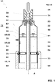
- Fig. 1 shows a compressed gas switch, in particular a circuit breaker, according to a first embodiment of the invention.
- gas blast switches are used in particular in high-voltage switchgear.
- the gas blast switch 10 has a tube 12 formed as a first contact 14, which is intended to cooperate with a formed as a pin 16 second contact 18 together.
- the first contact 14 as well as the second contact 18, at least at their free end portions of a Abbrandbe drivingn material, in particular of tungsten and copper, made.
- the tube 12 and the pin 16 are arranged on a common longitudinal axis A and movable relative to each other.
- the first contact 14 is designed to be movable.
- the associated drive assembly is not shown.
- the free end portion 20 of the first contact 14 is formed as a contact tulip with a plurality of contact fingers in a known manner.
- the free end portions of the contact fingers are preferably made of the erosion resistant material.
- a stationary conductor element 33 engages around the other end region of the separating element 30, which lies opposite the tapering end region 32 in the direction of the longitudinal axis A.
- a conductive connection between the conductor element 33 and the movable relative to the conductor element 33 separating element 30 is made by a contact spring 35.
- the contact can be made instead of a contact spring, for example, via a sliding contact, a spiral contact, a sliding tulip or a roller contact. This is inserted in a circumferential groove, which is formed radially inwardly in the free end region of the conductor element 33.
- the separator 30 is part of a well-known nominal current contact arrangement not shown in the figures.
- the separator 30 forms a first rated current contact and is electrically connected to the first contact 14.
- the second contact 18 is electrically connected to a second rated current contact, not shown, and is intended to cooperate with the first rated current contact, the separating element 30, when the compressed gas switch is closed.
- a nozzle body 34 is arranged, wherein the nozzle body 34 protrudes from the separating element 30 in the direction of the longitudinal axis A.
- the nozzle body 34 is preferably made of an insulating material, such as polytetrafluoroethylene. From the end projecting from the separating element 30, the nozzle body 34 initially has a nozzle opening 36, which tapers in the direction of the longitudinal axis A towards the first contact 14 and merges into a nozzle channel 38.
- the nozzle channel 38 expands on the opposite side of the nozzle opening 36 to an inner diameter which is larger than an outer diameter of the contact tulip of the first contact 14, wherein the inner diameter is selected such that the contact fingers of the contact tulip have a sufficiently large game.
- a gas channel 44 which connects the arc zone 40 with a heating chamber 46 in the interior of the separating element 30.
- This gas channel 44 is intended, on the one hand, to lead extinguishing gas, which is heated by an arc, from the arc zone 40 into the heating chamber 46.
- the gas channel 44 is intended to lead quenching gas from the heating chamber 46 for blowing the arc burning in the arc zone 40 into the arc zone 40.
- the heating chamber 46 has a constant volume.
- the heating chamber 46 is limited in the radial direction by the separating element 30. In the direction of the nozzle opening 36, the heating chamber is also delimited by the separating element 30 as well as by the nozzle body 34. In the opposite direction to the nozzle opening 36 of the heating chamber 46 is bounded by an intermediate wall-like intermediate member 48.
- the first contact element 14 is guided tightly through the intermediate element 48.
- the intermediate element 48 is preferably held on the separating element 30 in a form-fitting manner. It may also be positively secured to the first contact 14.
- an interior of the separating element 30 is subdivided into the heating space 46 and into a compression space 52.
- the compression space 52 is bounded on the side opposite the intermediate element 48 by a piston 56, which is arranged stationary in the present case.
- the piston 56 is part of a cylinder-piston arrangement, wherein the cavity of this cylinder-piston assembly is formed by the compression space 52.
- the piston 56 has a passage opening for the first contact 14. Between the piston 56 and the first contact 14 is a seal 80 in a recessed groove in the piston inserted to seal a gap between the first contact 14 and the piston 56. Furthermore, the seal 80 also forms a guide for the first contact 14. The piston 56 is sealed against the separating element 30 by means of a further seal 82, which is inserted into a further circumferential groove in the piston 56.
- an exhaust volume 58 On the opposite side of the compression chamber 52 of the piston 56 is located within the conductor element 33, an exhaust volume 58. This is connected by a pipe 12 formed in the flow channel 59 with the arc zone 40, so that extinguishing gas, which from the heating chamber 46 through the gas passage 44 into the Arc zone 40 flows through the flow channel 59 can flow into the exhaust volume 58. During a high-current phase, quenching gas can also flow directly from the arc zone 40 into the exhaust volume 58.
- a channel 60 which is closable by a designed as a check valve intermediate valve 62 that at an overpressure in the compression chamber 52 relative to the heating chamber 46 quenching gas from the compression chamber 52 flows into the heating chamber 46.
- the intermediate valve 62 closes.
- the low-pressure space 72 surrounds the rated-current contact arrangement. In the low-pressure space 72 prevails at least approximately during one Switching operation of the gas pressure switch 10, a constant gas pressure, which is preferably in the range of 3-7 bar.
- the low-pressure chamber 72 is bounded by a sheath, not shown, of the gas pressure switch and connected via a gas return to the exhaust volume 58.
- the flushing passage 66 can be closed in such a way by means of a flushing valve 74 designed as a check valve, that the flushing valve 74 opens at a negative pressure in the compression space 52 relative to the low-pressure space 72 and otherwise closes.
- the overpressure passage 68 can be closed by means of a pressure relief valve 76, which opens at a defined overpressure in the compression chamber 52 relative to the low pressure chamber 72 in order to build off any overpressure in the compression chamber 52.
- a plurality of flushing passages 66 can also be provided which can each be closed by means of a flushing valve 74.
- a plurality of overpressure passages 68 may be provided, each of which can be closed by means of a pressure relief valve 76.
- the in Fig. 1 shown gas pressure switch works as follows. First, the rated current contact arrangement is opened. Subsequently, the contact arrangement formed by the first contact 14 and the second contact 18 is separated, whereby an arc ignites in the arc zone 40 because of the current flow through the contact arrangement. As a result, quenching gas is heated. This flows initially through the gas passage 44 in the heating chamber 46. When opening the contact arrangement is also by the movement of the separating element 30 together with the first contact 14 in Direction of the longitudinal axis A away from the second contact 18 of the compression space 52 reduced, whereby the gas pressure in this increases.
- the gas pressure in the compression chamber 52 is greater than in the heating chamber 46, opens the intermediate valve 62, whereby quenching gas flows through the channel 60 from the compression chamber 52 into the heating chamber 46 and further increases the gas pressure in this. As soon as the gas pressure in the arc zone 40 decreases, quenching gas flows from the heating chamber 46 through the gas channel 44 into the arc zone 40 and inflates the arc, which is thereby extinguished.
- the gas pressure in the heating chamber 46 rapidly increases to a high value, the situation may arise that the intermediate valve 62 remains closed in the heating chamber 46 during the separation process of the contact arrangement, or at least over a longer Period of time during the separation process is closed. As a result, the extinguishing gas from the compression chamber 52 does not flow into the heating chamber 46. Upon reaching a predetermined gas pressure in the compression volume 52 now opens the pressure relief valve 76, which quenching gas can flow through the pressure passage 68 into the low-pressure chamber 72.
- the maximum pressure in the compression space 52 is defined by the response pressure of the pressure relief valve 76. It can thereby be achieved that a force necessary for opening the contact arrangement, in particular for retracting the separating element 30 together with the first contact 14 into the conductor element 33, does not exceed a maximum force. Thereby, the drive arrangement can be designed such that the contact arrangement can be reliably separated even at high current flow.
- the quenching gas used to blow the arc in the arc zone 40 flows on the one hand through the flow channel 59 into the exhaust volume 58 and on the other hand through the nozzle opening 36 from. In the exhaust volume 58, the hot quenching gas is cooled. A gas exchange between the exhaust volume 58 and the low pressure space 72 can take place via a not shown gas recirculation.
- the volume of the compression chamber 52 increases, whereby in this compared to the low-pressure chamber 72 as well as the heating chamber 46, a negative pressure is created.
- the inventive flushing valve 74 opens, which releases the flushing passage 66 for the flow of quenching gas from the low-pressure chamber 72 into the compression space 52.
- the purge valve 74 closes.
- the inflow of the quenching gas from the low-pressure space 72 into the blowing volume 54, in particular into the compression space 52 ensures that even shortly after opening the gas-blast switch cold extinguishing gas flows into the blowing volume 54 or in the compression space 52. As a result, it can be ensured that this works reliably in the case of briefly successive separation processes of the gas blast switch.
- inventive embodiment is omitted on the pressure relief valve 76 at the overpressure passage 68. Nevertheless, due to the clear diameter of the overpressure passage 68, the quenching gas flow can be controlled by the overpressure passage 68, in particular with an overpressure in the compression space 52 relative to the low-pressure space 72. Thus, when disconnecting the first contact 14 from the second contact 18, at the same time the volume of the compression chamber 52 is reduced, quenching gas from the compression chamber 52 into the low-pressure space 72 to flow. Consequently, the gas pressure in the compression space 52 can not increase arbitrarily.
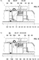
- Fig. 2 is another example of a gas blast switch shown. In essence, this embodiment corresponds to the in Fig. 1 It will be discussed here only on the differences.
- the separating element 30 has only the throughflow opening 64, which forms the overpressure passage 68 and can be closed by means of the overpressure valve 76.
- the separating element 30 preferably has a plurality of overpressure passages 68 closable by means of one or more pressure relief valves 76.
- 4-8 overpressure passages 68 are formed on the partition member 30.
- the overpressure passages 68 may also be formed as slots.
- intermediate element 48 is integrally formed with the tube 12 of the first contact 14.
- the intermediate piece and the tube 12 may also be formed of a plurality of individual elements.
- the intermediate element 48 has an open in the direction of the piston 56 annular channel 86, in which the overpressure passage 68 opens in the radial direction.
- the annular channel forms, together with the overpressure passage 68, a connecting channel 87.
- the annular channel 86 is delimited in the radial direction on the one hand by a wall 88 formed on the intermediate element 48 and on the other hand by the separating element 30.
- In the annular channel 86 is one in the direction of the longitudinal axis
- a slidably mounted annular disc 90 arranged as a valve disc. This is pressed by springs 92 in the direction of the opening of the annular channel 86, wherein a stop restricts the freedom of movement of the annular disc in the direction of the opening.
- the pressure relief valve 76 operates as follows. In the event of an overpressure in the compression space 52, the connection channel 87 adjoining the overpressure passage 68 is closed by the annular disk 90 located between the separating element 30 and the wall 88. As soon as the gas pressure in the compression chamber 52 rises above the response pressure of the pressure relief valve 76 defined by the springs 92, the annular disk 90 shifts in the axial direction A into the annular channel, into which Fig. 2 Position indicated by broken lines. In this position, the annular disk 90, the pressure relief valve 76 is opened and quenching gas can flow freely through the connecting channel 87 and the pressure relief passage 68 adjacent thereto.
- the piston 56 has a purge passage 66 ', which corresponds to that in connection with Fig. 1 Flushing passage 66 described by means of a designed as a check valve flush valve 74 'is closed.
- the purge passage 66 leads from the exhaust volume 58 into the compression space 52.
- intermediate member 48 of the channel 60 is performed in the direction of the longitudinal axis A.
- the intermediate element 48 has a plurality of circumferentially regularly arranged channels 60.
- the channel 60 or the channels 60 is / are closable by means of a valve plate of the intermediate valve 62.
- the valve plate is preferably in turn formed as a circular ring disk.
- the conductor element 33 is compared to in Fig. 1 shown embodiment in the direction of the longitudinal axis A is formed extended. Between the partition member 30 and the extended portion of the partition member 30, a gap 94 is formed. The overpressure passage 68 opens into this intermediate space 94. From the intermediate space 94, a channel 96 leads into the low-pressure space 72.
- FIG Fig. 3 A third exemplary embodiment according to the invention is shown in FIG Fig. 3 shown.
- Fig. 3 illustrated elements already related to Fig. 2 will be described on the description of Fig. 2 directed. Identical or equivalent parts are provided with the same reference numerals.
- the overpressure passage 68 also forms the purge passage 66 in this embodiment, that is, the purge passage 66 and the overpressure passage 68 are formed as a common flow passage 64.
- the purge passage 66 and the overpressure passage 68 are formed as a common flow passage 64.
- the flow-through opening 64 can be closed by a two-way valve 98.
- This two-way valve 98 opens at a negative pressure in the compression chamber 52 relative to the low-pressure chamber 72 and thus acts as a purge valve.
- the two-way valve 98 acts as a pressure relief valve, the two-way valve 98 opens only at a defined set pressure. As a result, a gas flow from the compression chamber 52 into the low-pressure space 72 is made possible.
- the two-way valve 98 may be formed as follows.
- the intermediate element 48 is the same as that associated with Fig. 2 described intermediate element formed with the open annular channel 86. In these opens the flow opening 64, which together with the annular channel 86 form the connecting channel 87. Of course, several flow openings can open into the annular channel 86.
- a slidably mounted annular disc 90 is arranged in the annular channel 86 in the direction of the longitudinal axis. This is pressed by springs in the direction of the opening of the annular channel 86, wherein a stop restricts the freedom of movement of the annular disc 90 in the direction of the opening of the annular channel 86.
- the annular disc 90 forms together with the spring and the stop for the annular disc 90, the pressure relief valve of the two-way valve 98.
- the annular disc 90 has a plurality of spaced from the edge of the annular disc 90 holes 100, through which each one in the direction of the longitudinal axis A. extending guide element 102 is guided.
- the guide element 102 is firmly connected to the intermediate element 48.
- a stop for a valve plate 104 is formed at the free end of the guide member 102.
- This valve disk 104 is freely movable on the guide element 102 between the stop and the annular disk 90 and forms the flushing valve of the two-way valve 98.
- the two-way valve 98 operates as follows. In the case of an overpressure in the compression space 52, the connecting channel 87 is closed by the annular disk 90 located between the separating element 30 and the wall 88. The holes 100 of the annular disc are closed by the valve plate 104. As soon as the gas pressure in the compression chamber 52 rises above the setpoint pressure of the two-way valve 98 acting as a pressure relief valve 98, the annular disk 90 moves together with the valve disks 104 in the axial direction A into the annular channel into the in Fig. 2 Position indicated by broken lines. In this position the Ring disk 90 and the valve disks 104 can discharge extinguishing gas from the compression chamber 52 through the connecting channel 87 into the low-pressure chamber 72.
- the intermediate element 48 is particularly preferably formed as a prefabricated assembly, which is inserted into the separating element 30 and the first contact 14 engages around.
- the intermediate element 48 are preferably in Fig. 1 shown purge valve 74, designed as a check valve overpressure valve 68 as well as the intermediate valve 62 is formed. This allows a particularly compact design of the gas blast switch can be achieved.
- the assembly of the gas pressure switch is significantly simplified thanks to the intermediate element 48.
- Fig. 4 are the flush valve and the pressure relief valve as related to Fig. 3 described as a two-way valve 98 is formed.
- axially displaceable annular disc of the intermediate valve 62 and the likewise axially displaceable valve plate 104 of the flushing valve 74 forming part of the two-way valve 98 instead by slidable in the direction of the longitudinal axis A through disks 106, 108 pivotable flaps formed, wherein the axis 106 of the intermediate valve 62 and the axis 108 of the flushing valve 74th forming part of the two-way valve 98 is assigned.
- a plurality of flaps are used for the intermediate valve 62 and for the purge valve 74 in the circumferential direction.
- Fig. 6 shows a compressed gas switch, in particular a circuit breaker, according to a sixth embodiment of the invention.
- gas blast switches are used in particular in high-voltage switchgear.
- the gas blast switch 10 has a tube 12 formed as a first contact 14, which is intended to cooperate with a formed as a pin 16 second contact 18 together.
- the first contact 14 as well as the second contact 18, at least at their free end portions of a Abbrandbe drivingn material, in particular of tungsten and copper, made.
- the tube 12 and the pin 16 are arranged on a common longitudinal axis A and movable relative to each other.
- the first contact 14 is designed to be movable.
- the associated drive assembly is not shown.
- the free end portion 20 of the first contact 14 is formed as a contact tulip with a plurality of contact fingers in a known manner.
- the free end portions of the contact fingers are preferably made of the erosion resistant material.
- first contact 14 around a hollow cylindrical shape having a separating element 30 is arranged, wherein the one end portion 32 of the partition member 30 tapers.
- the free end of the tapered end portion 32 is aligned in the direction of the longitudinal axis A substantially with the free end of the first contact 14.
- a stationary conductor element 33 engages around the other end region of the separating element 30, which is opposite to the tapered end portion 32 in the direction of the longitudinal axis A.
- a conductive connection between the conductor element 33 and the separating element 30 movable relative to the conductor element 33 is produced by a contact spring 35.
- the contact can be made instead of a contact spring, for example, via a sliding contact, a spiral contact, a sliding tulip or a roller contact.
- This contact spring 35 is inserted in a circumferential groove, which is formed radially inwardly in the free end region of the conductor element 33.
- the separator 30 is part of a well-known rated current contact arrangement, not shown in the figures.
- the separator 30 forms a first rated current contact and is electrically connected to the first contact 14.
- the second contact 18 is electrically connected to a second rated current contact, not shown, and is intended to cooperate with the first rated current contact, the separating element 30, when the compressed gas switch is closed.
- a nozzle body 34 is arranged, wherein the nozzle body 34 protrudes from the separating element 30 in the direction of the longitudinal axis A.
- the nozzle body 34 is preferably made of an insulating material, such as polytetrafluoroethylene. From the end projecting from the separating element 30, the nozzle body 34 initially has a nozzle opening 36, which tapers in the direction of the longitudinal axis A towards the first contact 14 and merges into a nozzle channel 38.
- the nozzle channel 38 expands on the opposite side of the nozzle opening 36 to an inner diameter which is larger than an outer diameter of the contact tulip of the first contact 14, wherein the inner diameter is selected such that the contact fingers of the contact tulip have a sufficiently large game.
- a gas channel 44 which connects the arc zone 40 with a heating chamber 46 in the interior of the separating element 30.
- This gas channel 44 is intended, on the one hand, to lead extinguishing gas, which is heated by an arc, from the arc zone 40 into the heating chamber 46.
- the gas channel 44 is intended to lead quenching gas from the heating chamber 46 for blowing the arc burning in the arc zone 40 into the arc zone 40.
- the heating chamber 46 has a constant volume.
- the heating chamber 46 is limited in the radial direction by the separating element 30. In the direction of the nozzle opening 36, the heating chamber 46 is likewise delimited by the separating element 30 as well as by the nozzle body 34. In the opposite direction to the nozzle opening 36 of the heating chamber 46 is bounded by an intermediate wall-like intermediate member 48.
- the first contact element 14 is guided tightly through the intermediate element 48.
- the intermediate element 48 is preferably held on the separating element 30 in a form-fitting manner. It may also be positively secured to the first contact 14.
- an interior of the separating element 30 is subdivided into the heating space 46 and into a compression space 52.
- the compression space 52 is bounded on the side opposite the intermediate element 48 by a piston 56, which is arranged stationary in the present case.
- the piston 56 is part of a cylinder-piston arrangement, wherein the cavity of this cylinder-piston assembly is formed by the compression space 52.
- the piston 56 has a passage opening for the first contact 14. Between the piston 56 and the first contact 14, a seal 80 is inserted in a circumferential groove in the piston to seal a gap between the first contact 14 and the piston 56. Furthermore, the seal 80 also forms a guide for the first contact 14. The piston 56 is sealed against the separating element 30 by means of a further seal 82, which is inserted into a further circumferential groove in the piston 56.
- an exhaust volume 58 On the opposite side of the compression chamber 52 of the piston 56 is located within the conductor element 33, an exhaust volume 58. This is connected by a pipe 12 formed in the flow channel 59 with the arc zone 40, so that extinguishing gas, which from the heating chamber 46 through the gas passage 44 into the Arc zone 40 flows through the flow channel 59 can flow into the exhaust volume 58. During a high-current phase, quenching gas can also flow directly from the arc zone 40 into the exhaust volume 58.
- a channel 60 which is closable by a designed as a check valve intermediate valve 62 that at an overpressure in the compression chamber 52 relative to the heating chamber 46 quenching gas from the compression chamber 52 flows into the heating chamber 46.
- the intermediate valve 62 closes.
- a flow-through opening 64 leads from the compression space 52 into a low-pressure space 72 radially adjoining the separating element 30.
- the low-pressure space 72 surrounds the rated-current contact arrangement.
- a constant gas pressure which is preferably in the range of 3-7 bar.
- the flow-through opening 64 ' not be closed by a valve.
- the flow-through opening is a non-closable flow-through opening 64 ', through which quenching gas can flow as well as can flow.
- the non-closable flow-through opening 64 ' leads in the radial direction with respect to the longitudinal axis A through the separating element 30. Consequently, a flow direction through the non-closable flow opening 64 'extends in the radial direction.
- the extinguishing gas flow through the non-closable flow-through opening 64' can be controlled, in particular with an overpressure in the compression space 52 relative to the low-pressure space 72. Consequently, in particular when the first contact 14 is separated from the second contact 18, the volume at the same time the compression space 52 is reduced, quenching gas from the compression chamber 52 in the low-pressure chamber 72 through the non-closable flow-through 64 'flow.
- a flow passage 64 forming a flushing passage 66 may be arranged parallel to the flow-through opening 64 ', which can not be closed. This in turn connects the low-pressure chamber 72 with the blowing volume 54, in particular with the compression chamber 52.
- the flushing passage 66 can be closed by means of a flushing valve 74 designed as a check valve so that the flushing valve 74 opens and otherwise closes when the vacuum chamber 72 is under reduced pressure in the compression chamber 52.
- the low-pressure chamber 72 is bounded by a sheath, not shown, of the gas pressure switch and connected via a gas return to the exhaust volume 58.
- flushing passages 66 can also be provided which can each be closed by means of a flushing valve 74.
- a plurality of non-closable flow openings 64 ' may be provided.
- the in Fig. 6 shown gas pressure switch operates when opening the gas pressure switch as follows. First, the rated current contact arrangement is opened. Subsequently, the contact arrangement formed by the first contact 14 and the second contact 18 is separated, whereby an arc in the arc zone 40 ignites due to the current flow through the contact arrangement. As a result, quenching gas is heated. This initially flows through the gas channel 44 into the heating chamber 46. When opening the contact arrangement is also reduced by the movement of the separating element 30 together with the first contact 14 in the direction of the longitudinal axis A away from the second contact 18 of the compression chamber 52, whereby the gas pressure in this increases.
- the gas pressure in the compression chamber 52 is greater than in the heating chamber 46, opens the intermediate valve 62, whereby quenching gas flows through the channel 60 from the compression chamber 52 into the heating chamber 46 and further increases the gas pressure in this. As soon as the gas pressure in the arc zone 40 decreases, quenching gas flows from the heating chamber 46 through the gas channel 44 into the arc zone 40 and inflates the arc, which is thereby extinguished.
- the gas pressure in the heating chamber 46 rapidly increases to a high value, the situation may occur that in the heating chamber 46 during the separation of the contact arrangement, the intermediate valve 62 remains closed, or at least closed over a longer period of time during the separation process. As a result, the extinguishing gas from the compression chamber 52 does not flow into the heating chamber 46. However, the quenching gas can flow through the non-closable flow-through opening 64 'into the low-pressure space 72. In this case, a greater pressure prevails in the compression chamber 52 than in the low-pressure chamber 72 and in the heating chamber 46 there is a greater pressure than in the compression chamber 52.
- the maximum pressure in the compression chamber 52 be defined by the clear diameter of the non-closable flow-through opening 64 '. It can thereby be achieved that a force necessary for opening the contact arrangement, in particular for retracting the separating element 30 together with the first contact 14 into the conductor element 33, does not exceed a maximum force.
- the drive arrangement can be designed such that the contact arrangement can be reliably separated even at high current flow.
- the extinguishing gas used to blow the arc in the arc zone 40 flows from the heating chamber 46 through the gas channel 44 to the arc zone 40 and then on the one hand through the flow channel 59 in the exhaust volume 58 and on the other hand through the nozzle opening 36 from.
- the hot quenching gas is cooled.
- a gas exchange between the exhaust volume 58 and the low pressure space 72 can take place via a not shown gas recirculation.
- the volume of the compression chamber 52 increases, whereby in this compared to the low-pressure chamber 72 as well as to the heating chamber 46, a negative pressure.
- quenching gas flows through the non-closable flow-through opening 64 'into the compression space 52.
- the purge valve 74 opens, which releases the purge passage 66 for the flow of quenching gas from the low-pressure space 72 into the compression space 52.
- the purge valve 74 closes.
- Fig. 7 a further embodiment of the inventive gas pressure switch is shown. In essence, this embodiment corresponds to the in Fig. 6 It will be discussed here only on the differences.
- the separating element 30 has in this embodiment only the non-closable flow-through opening 64 '.
- the non-closable flow-through openings 64 ' can also be formed as slots.
- intermediate element 48 is integrally formed with the tube 12 of the first contact 14.
- the intermediate piece and the tube 12 may also be formed of a plurality of individual elements.
- the piston 56 has a purge passage 66 ', which corresponds to that in connection with Fig. 6 Flushing passage 66 described by means of a designed as a check valve flush valve 74 'is closed.
- the purge passage 66 ' leads from the exhaust volume 58 into the compression space 52.
- intermediate member 48 of the channel 60 is performed in the direction of the longitudinal axis A.
- the intermediate element 48 has a plurality of circumferentially regularly arranged channels 60.
- the channel 60 or the channels 60 is / are closable by means of a valve plate of the intermediate valve 62.
- the valve plate is preferably in turn formed as a circular ring disk.
- the conductor element 33 is compared to in Fig. 1 shown embodiment in the direction of the longitudinal axis A is formed extended. Between the partition member 30 and the extended portion of the partition member 30, a gap 94 is formed. The non-closable flow-through opening 64 'opens into this intermediate space 94. From the intermediate space 94, a channel 96 leads into the low-pressure space 72.
Landscapes
- Circuit Breakers (AREA)
Description
- Die Erfindung bezieht sich auf das Gebiet der Mittelspannungsschaltertechnik und Hochspannungsschaltertechnik, insbesondere der Leistungsschalter in Energieverteilungsnetzen. Sie bezieht sich insbesondere auf einen Druckgasschalter gemäss dem Oberbegriff des Anspruchs 1 beziehungsweise des Anspruchs 5.
- Derartige Druckgasschalter sind insbesondere in der Hochspannungstechnik allgemein bekannt.
- Beispielsweise offenbart
WO 98/43265 - Der erste, antreibbare Lichtbogenkontakt ist von einem Schaltrohr getragen. An einem Ausgang dieses Schaltrohres ist ein Auspuffvolumen vorgesehen, in welches das Löschgas nach dem Beblasen des Lichtbogens geleitet wird. Das innerhalb der Nennstrombahn angeordnete Auspuffvolumen steht mit einem Niederdruckraum ausserhalb der Nennstrombahn über Ausblasöffnungen in Verbindung. Weiter ist das Auspuffvolumen durch eine Trennwand von einem Ansaugbereich getrennt, welcher zwischen Blasvolumen und Auspuffvolumen ebenfalls innerhalb der Nennstrombahn angeordnet ist. Dieser Ansaugbereich ist über ein Spülungsventil wie auch über ein Überdruckventil mit dem Blasvolumen verbunden. Durch die Trennwand ist das bewegliche Schaltrohr dicht hindurchgeführt.
- Dieser bekannte Druckgasschalter löst das Problem, dass im Ansaugbereich ein zumindest nahezu konstanter Gasdruck herrschen sollte, damit der Gasdruck im Auspuffvolumen keinen Einfluss auf die Funktion des Spülungsventils wie auch auf die Funktion des Überdruckventils hat. Als nachteilig erweist sich jedoch, dass die Trennwand innerhalb der Rohrförmig ausgebildeten Nennstrombahn angeordnet ist. Da die Trennwand während des Trennens des ersten Lichtbogenkontakt vom zweiten Lichtbogenkontakt einer hohen Druckdifferenz zwischen Ansaugbereich und Auspuffvolumen ausgesetzt ist, erfordert dies eine stabile Befestigung der Trennwand an einer Innenwandung der Nennstrombahn und eine dichte Durchführung des Schaltrohrs durch diese Trennwand hindurch.
- Weiter ist ebenfalls aus der
US 2003/01 73335 A1 und der zu dieser Schrift korrespondierendenDE 603 05 522 T2 ein Hochspannungs-Leistungsschalter bekannt. Dieser bekannte Leistungsschalter weist zwischen einer thermischen Kammer und einem Expansionsraum eine Evakuierungsleitung auf, die axialsymmetrisch zur Bewegungsachse der beweglichen Kontakte angeordnet ist. Die in axialer Richtung verlaufende Evakuierungsleitung ist mittels eines Ventils verschlossen, welches sich bei grossem Überdruck in der thermischen Lichtbogenlöschkammer öffnet. - Aus der
EP 0 146 671 A1 ist ein weiterer Druckgasschalter bekannt. Um beim Öffnen des Druckgasschalters einen Druck in einem Kolbenvolumen nicht über einen vorbestimmten Wert ansteigen zu lassen, weist dieser Druckgasschalter ein radial angeordnetes Überdruckventil auf. Dieses stellt sicher, dass bei einem übermässigen Überdruck im Kolbenvolumen Gas durch dieses Überdruckventil abströmen kann. - Aus
EP 0 296 363 A2 ist ein weiterer Druckgasschalter mit selbsterzeugter Löschgasströmung bekannt. Dieser Druckgasschalter weist einen Kompressionsraum auf. Um einen übermässigen Druck im Kompressionsraum zu verhindern, weist dieser Druckgasschalter ein Ventil auf, durch welches Gas aus dem Kompressionsraum radial ausströmen kann. -
FR 2 694 987 A1 - Aufgabe der vorliegenden Erfindung ist es, einen Druckgasschalter mit einer vereinfachten Bauweise vorzuschlagen, welcher dadurch ebenfalls ein kompakteres Design ermöglicht. Weiter soll der erfindungsgemässe Druckgasschalter eine grosse Zuverlässigkeit aufweisen.
- Die obige Aufgabe wird erfindungsgemäss durch einen Druckgasschalter mit den Merkmalen des Anspruchs 1 gelöst. Ebenso wird diese Aufgabe erfindungsgemäss durch einen Druckgasschalter mit den Merkmalen des Anspruchs 5 gelöst.
- Der erfindungsgemässe Druckgasschalter gemäss Anspruch 1 weist erfindungsgemäss eine einen Gasaustausch zwischen dem Niederdruckraum und dem Blasvolumen ermöglichende, unverschliessbare Durchströmöffnung auf. Die unverschliessbare Durchströmöffnung verläuft durch einen Bereich des Trennelements hindurch, der das Blasvolumen in radialer Richtung bezüglich der Längsachse vom Niederdruckraum abtrennt. Folglich kann insbesondere bei einem übermässigen Überdruck im Blasvolumen Löschgas aus dem Blasvolumen in den Niederdruckraum abströmen. Folglich kann der Gasdruck im Blasvolumen nicht beliebig ansteigen. Weiter ist ein besonders einfacher Aufbau des Druckgasschalters realisierbar.
- Gemäss einer bevorzugten Ausführungsform gemäss Anspruch 3 ist das Blasvolumen in einen Kompressionsraum und in einen Heizraum unterteilt, wobei die unverschliessbare Durchströmöffnung in den Kompressionsraum mündet. Dadurch kann erreicht werden, dass im Kompressionsraum der Druck nicht beliebig ansteigen kann und unverbrauchtes Löschgas vom Kompressionsraum in den Niederdruckraum abströmen kann. Ebenfalls kann auch Löschgas vom Niederdruckraum in den Kompressionsraum strömen.
- Gemäss einer bevorzugten Ausführungsform gemäss Anspruch 4 weist der Druckgasschalter eine weitere, verschliessbare Durchströmöffnung auf, die mittels eines als Rückschlagventil ausgebildeten Spülungsventil verschliessbar ist.
- Der erfindungsgemässe Druckgasschalter gemäss Anspruch 5 weist eine einen Gasaustausch ermöglichende Durchströmöffnung zwischen dem Niederdruckraum und einem Blasvolumen durch einen Bereich eines Trennelements hindurch auf, welches das Blasvolumen vom Niederdruckraum in radialer Richtung bezüglich der Längsachse des Druckgasschalters abtrennt. Erfindungsgemäss ist ein Spülungsventil in der beziehungsweise an der Durchströmöffnung angeordnet. Dadurch kann erreicht werden, dass zum Füllen des Blasvolumens mit Löschgas, dieses Löschgas aus dem Niederdruckraum in das Blasvolumen beziehungsweise in den Kompressionsraum strömen kann, jedoch nicht in umgekehrter Richtung. Da weiter auf der Seite des Niederdruckraums der Gasdruck zumindest annähernd konstant ist, öffnet das Spülungsventil bei einem vorbestimmten Druck, unabhängig vom Druckverlauf während des Schaltvorgangs.
- Das Blasvolumen des Druckgasschalters ist beispielsweise über einen Kanal mit einer Lichtbogenzone des Druckgasschalters verbunden, durch welchen während einer ersten Phase eines Ausschaltvorgangs aufgeheiztes Löschgas, wie beispielsweise SF6, (Schwefelhexafluorid) von der Lichtbogenzone in das Blasvolumen gelangt. Zu einer darauf folgenden, weiteren Phase strömt Löschgas aus dem Blasvolumen durch den Kanal zur Lichtbogenzone, um einen dort brennenden Lichtbogen zu beblasen. Das Löschgas strömt dann weiter in ein Auspuffvolumen ab.
- Mittels der Durchströmöffnung und dem Spülungsventil kann erreicht werden, dass Löschgas aus dem Niederdruckraum in das Blasvolumen strömen kann. Durch die erfindungsgemässe Führung der Durchströmöffnung in radialer Richtung kann der Druckgasschalter in Längsrichtung kompakt gebaut werden. Weiter erweist sich diese Verbindung des Niederdruckraums mit dem Blasvolumen als vorteilhaft, da im Niederdruckraum zu jedem Zeitpunkt des Schaltvorgangs zumindest annähernd ein konstanter Druck herrscht und das Löschgas im Niederdruckraum nicht ionisiert und kühl ist.
- Erfindungsgemäß ist das Spülungsventil offen, falls der Gasdruck auf der Seite des Niederdruckraums höher ist.
- Erfindungsgemäß sind das Spülungsventil und ein Überdruckventil in derselben bzw. an dieselbe Durchströmöffnung angeordnet, wobei das Spülungsventil und das Überdruckventil zusammen als ein Zwei-Weg-Ventil ausgebildet sind.
- Gemäss der Erfindung sind das Spülungsventil und ein Überdruckventil in derselben beziehungsweise an derselben Durchströmöffnung angeordnet. Dies ermöglicht eine besonders kompakte Bauweise des Druckgasschalters wie auch eine einfache Endmontage des Druckgasschalters. Insbesondere kann das Spülungsventil und das Überdruckventil als eine Baueinheit vormontiert werden.
- Bei einer weiteren bevorzugten Ausführungsform des Druckgasschalters weist der Druckgasschalter eine weitere Durchströmöffnung aufweist. Weiter ist in der bzw. an die weiter Durchströmöffnung ein Überdruckventil angeordnet, welches bei einem definierten Unterdruck auf der Seite des Niederdruckraums öffnet.
- Gemäss dieser bevorzugen Ausführungsform weist der Druckgasschalter eine weiter Durchströmöffnung auf, die mittels eines Überdruckventils verschliessbar ist. Dadurch kann erreicht werden, dass bei einem vorbestimmten Überdruck im Kompressionsraum beziehungsweise im Blasvolumen Löschgas in den Niederdruckraum abströmen kann. Da im Niederdruckraum zumindest annähernd ein konstanter Gasdruck herrscht, öffnet das Überdruckventil bei einem vorgegebenen Ansprechdruck. Dadurch kann erreicht werden, dass kein unerlaubt hoher Druck im Kompressionsraum bzw. im Blasvolumen aufgebaut wird. Dadurch kann verhindert werden, dass die Funktionsweise des Druckgasschalters aufgrund eines zu hohen Gasdrucks im Kompressionsraum bzw. im Blasvolumen beeinträchtigt wird.
- Bei einer weiteren bevorzugten Ausführungsform des Druckgasschalters ist das Überdruckventil und / oder das Spülungsventil in radialer Richtung zwischen dem Trennelement und der Längsachse des Druckgasschalters angeordnet.
- Gemäss einer bevorzugten Ausführungsform gemäss Anspruch 6 ist das Blasvolumen in einen Kompressionsraum und in einen Heizraum unterteilt, wobei die Durchströmöffnung in den Kompressionsraum mündet. Dadurch kann erreicht werden, dass unverbrauchtes Löschgas durch das Spülungsventil vom Niederdruckraum in den Kompressionsraum und durch das Überdruckventil vom Kompressionsraum in den Niederdruckraum strömen kann.
- Weiter weist der Druckgasschalter die Durchströmöffnung, insbesondere die unverschliessbare Durchströmöffnung, zwischen dem Niederdruckraum und dem Blasvolumen beziehungsweise dem Kompressionsraum auf. Durch die Durchströmöffnung kann auf einfachste weise eine Art Überdruckventil realisiert werden, wobei die Durchströmöffnung, falls kein Ventil diese verschliesst, immer offen ist. Durch die Wahl der Geometrie der Durchströmöffnung kann ein Gasdurchfluss durch diese gesteuert werden.
- Weitere bevorzugte Ausführungsformen und Vorteile gehen aus den weiteren abhängigen Patentansprüchen und den Figuren hervor.
- Im folgenden wird der Erfindungsgegenstand anhand von bevorzugten Ausführungsbeispielen näher erläutert, welche in den beiliegenden Zeichnungen dargestellt sind. Es zeigen rein schematisch:
- Fig. 1
- einen erfindungsgemässern Druckgasschalter, insbesondere einen Leistungsschalter, welcher zwei Durchströmöffnungen zwischen einem Niederdruckraum und einem Kompressionsraum aufweist, wobei die eine Durchströmöffnung durch ein Spülungsventil und die andere Durchströmöffnung durch ein Überdruckventil verschliessbar ist;
- Fig. 2
- eine Teilansicht eines Druckgasschalters, welche zum Verschliessen einer zwischen dem Niederdruckraum und dem Kompressionsraum ausgebildeten Durchströmöffnung ein Überdruckventil aufweist, welches in einer Baugruppe mit einem als Rückschlagventil ausgebildeten Zwischenventil zwischen dem Heizraum und dem Kompressionsraum ausgebildet ist;
- Fig. 3
- eine Teilansicht des erfindungsgemässen Druckgasschalters gemäss einem dritten Ausführungsbeispiel, in welchem zum Verschliessen der in
Fig. 2 gezeigten Durchströmöffnung zwischen Kompressionsraum und Niederdruckraum das Überdruckventil mit einem erfindungsgemässen Spülungsventil in einem Zwei-Weg-Ventil kombiniert ist; - Fig. 4
- eine Teilansicht des erfindungsgemässen Druckgasschalters gemäss einem vierten Ausführungsbeispiel;
- Fig. 5
- eine Teilansicht des erfindungsgemässen Druckgasschalters gemäss einem fünften Ausführungsbeispiel;
- Fig. 6
- einen erfindungsgemässern Druckgasschalter, insbesondere einen Leistungsschalter, welcher zwei Durchströmöffnungen zwischen einem Niederdruckraum und einem Kompressionsraum aufweist, wobei die eine Durchströmöffnung durch ein Spülungsventil verschliessbar ist und die andere Durchströmöffnung unverschliessbar ist; und
- Fig. 7
- einen erfindungsgemässen Druckgasschalter, der eine radial angeordnete, unverschliessbare Durchströmöffnung und ein axial angeordnetes Spülungsventil aufweist.
- Die in den Figuren verwendeten Bezugszeichen und deren Bedeutung sind in der Bezugszeichenliste zusammengefasst aufgelistet. Grundsätzlich sind in den Figuren gleiche oder gleichwirkende Teile mit gleichen oder ähnlichen Bezugszeichen versehen. Für das Verständnis der Erfindung nicht wesentliche Teile sind zum Teil nicht dargestellt. Die beschriebenen Ausführungsbeispiele stehen beispielhaft für den Erfindungsgegenstand und haben keine beschränkende Wirkung.
-
Fig. 1 zeigt einen Druckgasschalter, insbesondere einen Leistungsschalter, gemäss einem ersten Ausführungsbeispiel der Erfindung. Derartige Druckgasschalter werden insbesondere in Hochspannungsschaltanlagen verwendet. - Der Druckgasschalter 10 weist einen als Rohr 12 ausgebildeten ersten Kontakt 14 auf, der dazu bestimmt ist, mit einem als Stift 16 ausgebildeten zweiten Kontakt 18 zusammen zu wirken. Vorzugsweise sind der erste Kontakt 14 wie auch der zweite Kontakt 18 zumindest an ihren freien Endbereichen aus einem Abbrandbeständigen Material, insbesondere aus Wolfram und Kupfer, gefertigt. Das Rohr 12 und der Stift 16 sind auf einer gemeinsamen Längsachse A angeordnet und relativ zueinander beweglich. In dem in
Fig. 1 gezeigten Ausführungsbeispiel ist der erste Kontakt 14 bewegbar ausgebildet. Die zugehörige Antriebsanordnung ist nicht gezeigt. - Der freie Endbereich 20 des ersten Kontaktes 14 ist als eine Kontakttulpe mit mehreren Kontaktfingern in bekannter Art und Weise ausgebildet. Die freien Endbereiche der Kontaktfinger sind bevorzugt aus dem abbrandbeständigen Material gefertigt.
- Um den ersten Kontakt 14 herum ist ein eine Hohlzylinderform aufweisendes Trennelement 30 angeordnet, wobei der eine Endbereich 32 dieses Trennelements 30 sich verjüngt. Das freie Ende des verjüngten Endbereichs 32 ist in Richtung der Längsachse A im Wesentlichen mit dem freien Ende des ersten Kontaktes 14 ausgerichtet. In Umfangsrichtung umgreift ein stationäres Leiterelement 33 den anderen Endbereich des Trennelements 30, welcher dem sich verjüngenden Endbereich 32 in Richtung der Längsachse A gegenüberliegt. Eine leitende Verbindung zwischen dem Leiterelement 33 und dem relativ zum Leiterelement 33 beweglichen Trennelement 30 ist durch eine Kontaktfeder 35 hergestellt. Der Kontakt kann anstelle über eine Kontaktfeder beispielsweise auch über einen Gleitkontakt, einen Spiralkontakt, eine Gleittulpe oder einen Rollenkontakt hergestellt sein. Diese ist in eine umlaufende Nute eingelegt, welche im freien Endbereich des Leiterelements 33 radial innenliegend ausgebildet ist.
- Das Trennelement 30 ist Teil einer in den Figuren nicht gezeigten allgemein bekannten Nennstromkontaktanordnung. Das Trennelement 30 bildet einen ersten Nennstromkontakt und ist elektrisch mit dem ersten Kontakt 14 verbunden. Der zweite Kontakt 18 ist mit einem nicht gezeigten zweiten Nennstromkontakt elektrisch leitend verbunden und ist dazu bestimmt, mit dem ersten Nennstromkontakt, dem Trennelement 30, bei geschlossenem Druckgasschalter zusammen zu wirken.
- In den verjüngten Endbereich 32 des Trennelements 30 ist ein Düsenkörper 34 angeordnet, wobei der Düsenkörper 34 aus dem Trennelement 30 in Richtung der Längsachse A heraus ragt. Der Düsenkörper 34 ist bevorzugt aus einem Isolierstoff, wie beispielsweise Polytetrafluoräthylen, gefertigt. Der Düsenkörper 34 weist vom aus dem Trennelement 30 herausragenden Ende her zunächst eine Düsenöffnung 36 auf, welche sich in Richtung der Längsachse A zum ersten Kontakt 14 hin verjüngt und in einen Düsenkanal 38 übergeht. Der Düsenkanal 38 erweitert sich auf der der Düsenöffnung 36 gegenüberliegenden Seite auf einen Innendurchmesser, der grösser ist als ein Aussendruchmesser der Kontakttulpe des ersten Kontaktes 14, wobei der Innendurchmesser derart gewählt ist, dass die Kontaktfinger der Kontakttulpe ein genügend grosses Spiel haben. Der Bereich innerhalb des Düsenkörpers 34, der zwischen der Kontakttulpe und dem freien Ende liegt, bildet eine Lichtbogenzone 40.
- In den Düsenkanal 38 mündet ein Gaskanal 44, der die Lichtbogenzone 40 mit einem Heizraum 46 im Inneren des Trennelements 30 verbindet. Dieser Gaskanal 44 ist zum einen dazu bestimmt, Löschgas, welches durch einen Lichtbogen aufgeheizt wird, von der Lichtbogenzone 40 in den Heizraum 46 zu führen. Zum anderen ist der Gaskanal 44 dazu bestimmt, Löschgas aus dem Heizraum 46 zum Beblasen des in der Lichtbogenzone 40 brennenden Lichtbogens in die Lichtbogenzone 40 zu führen. Typischerweise weist der Heizraum 46 ein konstantes Volumen auf.
- Der Heizraum 46 ist in radialer Richtung durch das Trennelement 30 begrenzt. In Richtung der Düsenöffnung 36 ist der Heizraum ebenfalls durch das Trennelement 30 wie auch durch den Düsenkörper 34 begrenzt. In entgegengesetzter Richtung zur Düsenöffnung 36 ist der Heizraum 46 durch ein zwischenwandartiges Zwischenelement 48 begrenzt. Das erste Kontaktelement 14 ist durch das Zwischenelement 48 dicht hindurch geführt. Das Zwischenelement 48 ist vorzugsweise formschlüssig am Trennelement 30 gehalten. Es kann ebenfalls formschlüssig am ersten Kontakt 14 befestigt sein.
- Durch das Zwischenelement 48 wird ein Innenraum des Trennelements 30 in den Heizraum 46 und in einen Kompressionsraum 52 unterteilt. Das Innere des Trennelements 30 - der Heizraum 46 und der Kompressionsraum 52 - bilden zusammen ein Blasvolumen 54. Der Kompressionsraum 52 wird auf der dem Zwischenelement 48 gegenüberliegenden Seite durch einen Kolben 56 begrenzt, der im vorliegenden Fall ortsfest angeordnet ist. Der Kolben 56 ist Teil einer Zylinder-Kolben-Anordnung, wobei der Hohlraum dieser Zylinder-Kolben-Anordnung durch den Kompressionsraum 52 gebildet ist.
- Der Kolben 56 weist eine Durchgangsöffnung für den ersten Kontakt 14 auf. Zwischen dem Kolben 56 und dem ersten Kontakt 14 ist eine Dichtung 80 in eine im Kolben umlaufende Nute eingelegt, um einen Spalt zwischen dem ersten Kontakt 14 und dem Kolben 56 abzudichten. Weiter bildet die Dichtung 80 auch eine Führung für den ersten Kontakt 14. Der Kolben 56 ist gegen das Trennelement 30 mittels einer weiteren Dichtung 82 abgedichtet, welche in eine weitere umlaufende Nute im Kolben 56 eingelegt ist.
- Auf der dem Kompressionsraum 52 gegenüberliegenden Seite des Kolbens 56 liegt innerhalb des Leiterelements 33 ein Auspuffvolumen 58. Dieses ist durch einen im Rohr 12 ausgebildeten Strömungskanal 59 mit der Lichtbogenzone 40 verbunden, sodass Löschgas, welches aus dem Heizraum 46 durch den Gaskanal 44 hindurch in die Lichtbogenzone 40 strömt, durch den Strömungskanal 59 in das Auspuffvolumen 58 abströmen kann. Während einer Hochstromphase kann Löschgas auch direkt aus der Lichtbogenzone 40 in das Auspuffvolumen 58 strömen.
- Durch das Zwischenelement 48 führt vom Kompressionsraum 52 in den Heizraum 46 ein Kanal 60, der derart durch ein als Rückschlagventil ausgebildetes Zwischenventil 62 verschliessbar ist, dass bei einem Überdruck im Kompressionsraum 52 relativ zum Heizraum 46 Löschgas vom Kompressionsraum 52 in den Heizraum 46 strömt. Bei einem Überdruck im Heizraum 46 relativ zum Kompressionsraum 52 schliesst das Zwischenventil 62.
- In radialer Richtung ist ein eine Durchströmöffnung 64 bildender Spülungsdurchlass 66 und ein ebenfalls eine Durchströmöffnung 64 bildender Überdruckdurchlass 68 vom Kompressionsraum 52 in einen an das Trennelement 30 radial aussen angrenzenden Niederdruckraum 72. Der Niederdruckraum 72 umgibt die Nennstromkontaktanordnung. Im Niederdruckraum 72 herrscht zumindest annähernd während eines Schaltvorgangs des Druckgasschalters 10 ein konstanter Gasdruck, der vorzugsweise im Bereich von 3-7 Bar liegt.
- Der Niederdruckraum 72, ist durch eine nicht gezeigte Umhüllung des Druckgasschalters begrenzt und über eine Gasrückführung mit dem Auspuffvolumen 58 verbunden.
- Der Spülungsdurchlass 66 ist erfindungsgemäss mittels eines als Rückschlagventil ausgebildeten Spülungsventils 74 derart verschliessbar, dass bei einem Unterdruck im Kompressionsraum 52 relativ zum Niederdruckraum 72 das Spülungsventil 74 öffnet und ansonsten schliesst. Der Überdruckdurchlass 68 kann mittels eines Überdruckventils 76 verschliessbar sein, welches bei einem definierten Überdruck im Kompressionsraum 52 relativ zum Niederdruckraum 72 öffnet, um einen allfälligen Überdruck im Kompressionsraum 52 ab zu bauen. Selbstverständlich können auch mehrer Spülungsdurchlässe 66 vorgesehen sein, die jeweils mittels eines Spülungsventils 74 verschliessbar sind. Ebenso können mehrer Überdruckdurchlässe 68 vorgesehen sein, die jeweils mittels eines Überdruckventils 76 verschliessbar sind.
- Der in
Fig. 1 gezeigte Druckgasschalter arbeitet wie folgt. Zunächst wird die Nennstromkontaktanordnung geöffnet. Darauf folgend wird die durch den ersten Kontakt 14 und den zweiten Kontakt 18 gebildeten Kontaktanordnung getrennt, wodurch wegen des Stromflusses durch die Kontaktanordnung ein Lichtbogen in der Lichtbogenzone 40 zündet. Dadurch wird Löschgas aufgeheizt. Dieses strömt anfänglich durch den Gaskanal 44 in den Heizraum 46. Beim Öffnen der Kontaktanordnung wird zudem durch die Bewegung des Trennelements 30 zusammen mit dem ersten Kontakts 14 in Richtung der Längsachse A weg vom zweiten Kontakt 18 der Kompressionsraum 52 verkleinert, wodurch der Gasdruck in diesem steigt. Falls der Gasdruck im Kompressionsraum 52 grösser ist als im Heizraum 46, öffnet das Zwischenventil 62, wodurch Löschgas durch den Kanal 60 hindurch aus dem Kompressionsraum 52 in den Heizraum 46 einströmt und in diesem den Gasdruck weiter erhöht. Sobald der Gasdruck in der Lichtbogenzone 40 abnimmt, strömt Löschgas aus dem Heizraum 46 durch den Gaskanal 44 in die Lichtbogenzone 40 und bebläst den Lichtbogen, welcher dadurch gelöscht wird. - Falls jedoch wegen eines starken Stromflusses, beispielsweise ausgelöst durch einen Erdschluss, der Gasdruck im Heizraum 46 rasch auf einen hohen Wert ansteigt, kann die Situation auftreten, dass im Heizraum 46 während des Trennvorgangs der Kontaktanordnung das Zwischenventil 62 geschlossen bleibt, oder zumindest über eine längere Zeitspanne während des Trennvorgangs geschlossen ist. Dadurch kann das Löschgas aus dem Kompressionsraum 52 nicht in den Heizraum 46 abströmen. Bei erreichen eines vorbestimmten Gasdrucks im Kompressionsvolumen 52 öffnet nun das Überdruckventil 76, wodurch Löschgas durch den Überdruckdurchlass 68 in den Niederdruckraum 72 abströmen kann. Da im Niederdruckraum 72, insbesondere während des Trennvorgangs, ein zumindest nahezu konstanter Gasdruck herrscht, ist der Maximaldruck im Kompressionsraum 52 durch den Ansprechdruck des Überdruckventils 76 definiert. Dadurch kann erreicht werden, dass eine notwendige Kraft zum Öffnen der Kontaktanordnung, insbesondere zum Einfahren des Trennelements 30 zusammen mit dem ersten Kontakt 14 in das Leiterelement 33 hinein, eine Maximalkraft nicht übersteigt. Dadurch kann die Antriebsanordnung derart ausgelegt werden, dass die Kontaktanordnung auch bei hohem Stromfluss zuverlässig getrennt werden kann.
- Das zum Beblasen des Lichtbogens in der Lichtbogenzone 40 verwendete Löschgas strömt einerseits durch den Strömungskanal 59 in das Auspuffvolumen 58 und andererseits durch die Düsenöffnung 36 ab. Im Auspuffvolumen 58 wird das heisse Löschgas gekühlt. Ein Gasaustausch zwischen Auspuffvolumen 58 und Niederdruckraum 72 kann über eine nicht gezeigt Gasrückführung erfolgen.
- Beim Schliessen der Kontaktanordnung vergrössert sich das Volumen des Kompressionsraums 52, wodurch in diesem im Vergleich zum Niederdruckraum 72 wie auch zum Heizraum 46 ein Unterdruck entsteht. Dadurch öffnet sich das erfindungsgemässe Spülungsventil 74, welches den Spülungsdurchlass 66 zum Einströmen von Löschgas aus dem Niederdruckraum 72 in den Kompressionsraum 52 frei gibt. Sobald der Gasdruck im Kompressionsvolumen 52 über den Gasdruck im Niederdruckraum 72 ansteigt, schliesst das Spülungsventil 74. Durch das Einströmen des Löschgases aus dem Niederdruckraum 72 in das Blasvolumen 54, insbesondere in den Kompressionsraum 52, ist sichergestellt, dass selbst kurz nach dem Öffnen des Druckgasschalters kaltes Löschgas in das Blasvolumen 54 bzw. in den Kompressionsraum 52 einströmt. Dadurch kann sichergestellt werden, dass bei kurz aufeinander folgenden Trennvorgängen des Druckgasschalters dieses zuverlässig funktioniert.
- In einem in
Fig. 6 gezeigten und im Zusammenhang mitFig. 6 ausführlich beschrieben, erfindungsgemässen Ausführungsbeispiel, wird auf das Überdruckventil 76 am Überdruckdurchlass 68 verzichtet. Durch den lichten Durchmesser des Überdruckdurchlass 68 kann dennoch der Löschgasfluss durch den Überdruckdurchlass 68, insbesondere bei einem Überdruck im Kompressionsraum 52 relativ zum Niederdruckraum 72, gesteuert werden. Folglich kann beim Trennen des ersten Kontakts 14 vom zweiten Kontakt 18, wobei gleichzeitig das Volumen des Kompressionsraums 52 verringert wird, Löschgas aus dem Kompressionsraum 52 in den Niederdruckraum 72 abströmen. Folglich kann der Gasdruck im Kompressionsraum 52 nicht beliebig ansteigen. - In
Fig. 2 ist ein weiteres Beispiel eines Druckgasschalters gezeigt. Im Wesentlichen entspricht dieses Ausführungsbeispiel dem inFig. 1 dargestellten Druckgasschalter 10. Es wird hier nur auf die Unterschiede eingegangen. - Das Trennelement 30 weist in dieser Ausführungsform nur die Durchströmöffnung 64 auf, welche den Überdruckdurchlass 68 bildet und mittels des Überdruckventils 76 verschliessbar ist. Vorzugsweise weist das Trennelement 30 mehrer mittels eines oder mehreren Überdruckventilen 76 verschliessbare Überdruckdurchlässe 68 auf. Vorzugsweise sind am Trennelement 30 zwischen 4-8 Überdruckdurchlässe 68 ausgebildet. Die Überdruckdurchlässe 68 können auch als Schlitze ausgebildet sein.
- Das in
Fig. 2 gezeigte Zwischenelement 48 ist einstückig mit dem Rohr 12 des ersten Kontakts 14 ausgebildet. Selbstverständlich kann das Zwischenstück und das Rohr 12 auch aus mehreren Einzelelementen bestehend ausgebildet sein. - Um das Überdruckventil 76 auszubilden, weist das Zwischenelement 48 einen in Richtung des Kolbens 56 offenen Ringkanal 86 auf, in welchen der Überdruckdurchlass 68 in radialer Richtung mündet. Der Ringkanal bildet zusammen mit dem Überdruckdurchlass 68 einen Verbindungskanal 87. Der Ringkanal 86 ist in radialer Richtung einerseits durch eine am Zwischenelement 48 ausgebildete Wand 88 und andererseits durch das Trennelement 30 begrenzt. Im Ringkanal 86 ist eine in Richtung Längsachse A verschiebbar gelagerte Ringscheibe 90 als Ventilscheibe angeordnet. Diese wird von Federn 92 in Richtung der Öffnung des Ringkanals 86 gepresst, wobei ein Anschlag die Bewegungsfreiheit der Ringscheibe in Richtung der Öffnung beschränkt.
- Das Überdruckventil 76 arbeitet wie folgt. Bei einem Überdruck im Kompressionsraum 52 ist der an den Überdruckdurchlass 68 anschliessende Verbindungskanal 87 durch die zwischen dem Trennelement 30 und der Wand 88 liegende Ringscheibe 90 verschlossen. Sobald der Gasdruck im Kompressionsraum 52 über den durch die Federn 92 definierten Ansprechdruck des Überdruckventils 76 ansteigt, verschiebt sich die Ringscheibe 90 in Axialrichtung A in den Ringkanal hinein, in die in
Fig. 2 mit durchbrochenen Linien angedeutete Stellung. In dieser Stellung der Ringscheibe 90 ist das Überdruckventil 76 geöffnet und Löschgas kann ungehindert durch den Verbindungskanal 87 und den daran angrenzenden Überdruckdurchlass 68 abströmen. - Der Kolben 56 weist einen Spülungsdurchlass 66' auf, welcher entsprechend dem im Zusammenhang mit
Fig. 1 beschriebenen Spülungsdurchlass 66 mittels eines als Rückschlagventil ausgebildeten Spülungsventils 74' verschliessbar ist. Der Spülungsdurchlass 66 führt vom Auspuffvolumen 58 in den Kompressionsraum 52. - Durch das am ersten Kontakt 14 angeordnete Zwischenelement 48 ist der Kanal 60 in Richtung der Längsachse A durchgeführt. Vorzugsweise weist das Zwischenelement 48 mehrere, in Umfangsrichtung regelmässig angeordnete Kanäle 60 auf. Der Kanal 60 beziehungsweise die Kanäle 60 ist / sind mittels eines Ventilblechs des Zwischenventils 62 verschliessbar. Das Ventilblech ist vorzugsweise wiederum als Kreisringscheibe ausgebildet.
- Das Leiterelement 33 ist im Verglich zum in
Fig. 1 gezeigten Ausführungsbeispiel in Richtung der Längsachse A verlängert ausgebildet. Zwischen dem Trennelement 30 und dem verlängerten Abschnitt des Trennelements 30 ist ein Zwischenraum 94 ausgebildet. Der Überdruckdurchlass 68 mündet in diesen Zwischenraum 94. Vom Zwischenraum 94 führt ein Kanal 96 in den Niederdruckraum 72. - Ein erfindungsgemässes, drittes Ausführungsbeispiel ist in
Fig. 3 dargestellt. Für die inFig. 3 dargestellten Elemente, die bereits im Zusammenhang mitFig. 2 beschrieben wurden, wird auf die Beschreibung vonFig. 2 verwiesen. Gleiche oder gleich wirkende Teile sind mit denselben Bezugszeichen versehen. - Der Überdruckdurchlass 68 bildet in diesem Ausführungsbeispiel ebenfalls den Spülungsdurchlass 66, das heisst, der Spülungsdurchlass 66 und der Überdruckdurchlass 68 sind als eine gemeinsame Durchströmöffnung 64 ausgebildet. Auf den in Zusammenhang mit
Fig. 2 beschriebene Spülungsdurchlass durch den Kolben 56 hindurch wird in diesem Ausführungsbeispiel verzichtet. - Die Durchströmöffnung 64 ist durch ein Zwei-Weg-Ventil 98 verschliessbar. Dieses Zwei-Weg-Ventil 98 öffnet bei einem Unterdruck im Kompressionsraum 52 relativ zum Niederdruckraum 72 und wirkt folglich als Spülungsventil. Bei Überdruck im Kompressionsraum 52 relativ zum Niederdruckraum 72 wirkt das Zwei-Weg-Ventil 98 als Überdruckventil, wobei das Zwei-Weg-Ventil 98 erst bei einem definierten Ansprechdruck öffnet. Dadurch ist ein Gasfluss vom Kompressionsraum 52 in den Niederdruckraum 72 ermöglicht.
- Das Zwei-Weg-Ventil 98 kann wie folgt ausgebildet sein. Das Zwischenelement 48 ist gleich wie das im Zusammenhang mit
Fig. 2 beschriebene Zwischenelement mit dem offenen Ringkanal 86 ausgebildet. In diesen mündet die Durchströmöffnung 64, welche zusammen mit dem Ringkanal 86 den Verbindungskanal 87 bilden. Selbstverständlich können auch mehrer Durchströmöffnungen in den Ringkanal 86 münden. Im Ringkanal 86 ist die in Richtung der Längsachse A verschiebbar gelagerte Ringscheibe 90 angeordnet. Diese wird von Federn in Richtung der Öffnung des Ringkanals 86 gepresst, wobei ein Anschlag die Bewegungsfreiheit der Ringscheibe 90 in Richtung der Öffnung des Ringkanals 86 beschränkt. Die Ringscheibe 90 bildet zusammen mit der Feder und dem Anschlag für die Ringscheibe 90 das Überdruckventil des Zwei-Weg-Ventils 98. Die Ringscheibe 90 weist mehrer, vom Rand der Ringscheibe 90 beabstandete Löcher 100 auf, durch welche je ein in Richtung der Längsachse A verlaufendes Führungselement 102 hindurch geführt ist. Das Führungselement 102 ist fest mit dem Zwischenelement 48 verbunden. Am freien Ende des Führungselements 102 ist ein Anschlag für einen Ventilteller 104 ausgebildet. Dieser Ventilteller 104 ist auf dem Führungselement 102 zwischen dem Anschlag und der Ringscheibe 90 frei beweglich und bildet das Spülungsventil des Zwei-Weg-Ventils 98. - Das Zwei-Weg-Ventil 98 arbeitet wie folgt. Bei einem Überdruck im Kompressionsraum 52 ist der Verbindungskanal 87 durch die zwischen dem Trennelement 30 und der Wand 88 liegende Ringscheibe 90 verschlossen. Die Löcher 100 der Ringscheibe sind durch die Ventilteller 104 verschlossen. Sobald der Gasdruck im Kompressionsraum 52 über den durch die Federn 92 definierten Ansprechdruck des als Überdruckventil wirkenden Zwei-Weg-Ventils 98 ansteigt, verschiebt sich die Ringscheibe 90 zusammen mit den Ventilscheiben 104 in Axialrichtung A in den Ringkanal hinein in die in
Fig. 2 mit durchbrochenen Linien angedeutet Stellung. In dieser Stellung der Ringscheibe 90 und der Ventilscheiben 104 kann Löschgas aus dem Kompressionsraum 52 durch den Verbindungskanal 87 hindurch in den Niederdruckraum 72 abströmen. - Falls im Kompressionsraum 52 im Vergleich zum Niederdruckraum 72 ein Unterdruck herrscht (dieser Fall ist in
Fig. 3 dargestellt), öffnet das Zwei-Weg-Ventil 98, indem die Ventilscheiben 104 von der Ringscheibe sich aufgrund des Druckunterschieds entfernen. Dadurch werden die Löcher 100 der Ringscheibe freigegeben, wodurch Löschgas vom Niederdruckraum 72 in den Kompressionsraum 52 einströmen kann. - Wie in
Fig. 4 gezeigt, wird besonders bevorzugt das Zwischenelement 48 als eine vorgefertigte Baugruppe ausgebildet, die in das Trennelement 30 eingesetzt wird und den ersten Kontakt 14 umgreift. Am Zwischenelement 48 sind bevorzugt das inFig. 1 gezeigte Spülungsventil 74, das als Rückschlagventil ausgebildete Überdruckventil 68 wie auch das Zwischenventil 62 ausgebildet. Dadurch kann eine besonders kompakte Bauweise des Druckgasschalters erzielt werden. Weiter wird die Montage des Druckgasschalters dank des Zwischenelements 48 wesentlich vereinfacht. InFig. 4 sind das Spülungsventil und das Überdruckventil wie im Zusammenhang mitFig. 3 beschrieben als Zwei-Weg-Ventil 98 ausgebildet. - In einem in
Fig. 5 dargestellten fünften Ausführungsbeispiel, welches weitgehend gleich wie das inFig. 4 gezeigten Ausführungsbeispiel ausgebildet ist, sind die axial verschiebbare Kreisringscheibe des Zwischenventil 62 und der ebenfalls axial verschiebbare Ventilteller 104 des das Spülungsventil 74 bildenden Teils des Zwei-Weg-Ventils 98 anstatt durch in Richtung der Längsachse A verschiebbare Scheiben durch um Achsen 106, 108 schwenkbare Klappen ausgebildet, wobei die Achse 106 dem Zwischenventil 62 und die Achse 108 dem das Spülungsventil 74 bildenden Teils des Zwei-Weg-Ventils 98 zugeordnet ist. Vorzugsweise werden für das Zwischenventil 62 und für das Spülungsventil 74 in Umfangsrichtung jeweils mehrere Klappen verwendet. -
Fig. 6 zeigt einen Druckgasschalter, insbesondere einen Leistungsschalter, gemäss einem sechsten Ausführungsbeispiel der Erfindung. Derartige Druckgasschalter werden insbesondere in Hochspannungsschaltanlagen verwendet. - Der Druckgasschalter 10 weist einen als Rohr 12 ausgebildeten ersten Kontakt 14 auf, der dazu bestimmt ist, mit einem als Stift 16 ausgebildeten zweiten Kontakt 18 zusammen zu wirken. Vorzugsweise sind der erste Kontakt 14 wie auch der zweite Kontakt 18 zumindest an ihren freien Endbereichen aus einem Abbrandbeständigen Material, insbesondere aus Wolfram und Kupfer, gefertigt. Das Rohr 12 und der Stift 16 sind auf einer gemeinsamen Längsachse A angeordnet und relativ zueinander beweglich. In dem in
Fig. 1 gezeigten Ausführungsbeispiel ist der erste Kontakt 14 bewegbar ausgebildet. Die zugehörige Antriebsanordnung ist nicht gezeigt. - Der freie Endbereich 20 des ersten Kontaktes 14 ist als eine Kontakttulpe mit mehreren Kontaktfingern in bekannter Art und Weise ausgebildet. Die freien Endbereiche der Kontaktfinger sind bevorzugt aus dem abbrandbeständigen Material gefertigt.
- Um den ersten Kontakt 14 herum ist ein eine Hohlzylinderform aufweisendes Trennelement 30 angeordnet, wobei der eine Endbereich 32 dieses Trennelements 30 sich verjüngt. Das freie Ende des verjüngten Endbereichs 32 ist in Richtung der Längsachse A im Wesentlichen mit dem freien Ende des ersten Kontaktes 14 ausgerichtet. In Umfangsrichtung umgreift ein stationäres Leiterelement 33 den anderen Endbereich des Trennelements 30, welcher dem sich verjüngenden Endbereich 32 in Richtung der Längsachse A gegenüberliegt. Eine leitende Verbindung zwischen dem Leiterelement 33 und dem relativ zum Leiterelement 33 beweglichen Trennelement 30 ist durch eine Kontaktfeder 35 hergestellt. Der Kontakt kann anstelle über eine Kontaktfeder beispielsweise auch über einen Gleitkontakt, einen Spiralkontakt, eine Gleittulpe oder einen Rollenkontakt hergestellt sein. Diese Kontaktfeder 35 ist in eine umlaufende Nute eingelegt, welche im freien Endbereich des Leiterelements 33 radial innenliegend ausgebildet ist.
- Das Trennelement 30 ist Teil einer in den Figuren nicht gezeigten, allgemein bekannten Nennstromkontaktanordnung. Das Trennelement 30 bildet einen ersten Nennstromkontakt und ist elektrisch mit dem ersten Kontakt 14 verbunden. Der zweite Kontakt 18 ist mit einem nicht gezeigten zweiten Nennstromkontakt elektrisch leitend verbunden und ist dazu bestimmt, mit dem ersten Nennstromkontakt, dem Trennelement 30, bei geschlossenem Druckgasschalter zusammen zu wirken.
- In den verjüngten Endbereich 32 des Trennelements 30 ist ein Düsenkörper 34 angeordnet, wobei der Düsenkörper 34 aus dem Trennelement 30 in Richtung der Längsachse A heraus ragt. Der Düsenkörper 34 ist bevorzugt aus einem Isolierstoff, wie beispielsweise Polytetrafluoräthylen, gefertigt. Der Düsenkörper 34 weist vom aus dem Trennelement 30 herausragenden Ende her zunächst eine Düsenöffnung 36 auf, welche sich in Richtung der Längsachse A zum ersten Kontakt 14 hin verjüngt und in einen Düsenkanal 38 übergeht. Der Düsenkanal 38 erweitert sich auf der der Düsenöffnung 36 gegenüberliegenden Seite auf einen Innendurchmesser, der grösser ist als ein Aussendruchmesser der Kontakttulpe des ersten Kontaktes 14, wobei der Innendurchmesser derart gewählt ist, dass die Kontaktfinger der Kontakttulpe ein genügend grosses Spiel haben. Der Bereich innerhalb des Düsenkörpers 34, der zwischen der Kontakttulpe und dem freien Ende liegt, bildet eine Lichtbogenzone 40.
- In den Düsenkanal 38 mündet ein Gaskanal 44, der die Lichtbogenzone 40 mit einem Heizraum 46 im Inneren des Trennelements 30 verbindet. Dieser Gaskanal 44 ist zum einen dazu bestimmt, Löschgas, welches durch einen Lichtbogen aufgeheizt wird, von der Lichtbogenzone 40 in den Heizraum 46 zu führen. Zum anderen ist der Gaskanal 44 dazu bestimmt, Löschgas aus dem Heizraum 46 zum Beblasen des in der Lichtbogenzone 40 brennenden Lichtbogens in die Lichtbogenzone 40 zu führen. Typischerweise weist der Heizraum 46 ein konstantes Volumen auf.
- Der Heizraum 46 ist in radialer Richtung durch das Trennelement 30 begrenzt. In Richtung der Düsenöffnung 36 ist der Heizraum 46 ebenfalls durch das Trennelement 30 wie auch durch den Düsenkörper 34 begrenzt. In entgegengesetzter Richtung zur Düsenöffnung 36 ist der Heizraum 46 durch ein zwischenwandartiges Zwischenelement 48 begrenzt. Das erste Kontaktelement 14 ist durch das Zwischenelement 48 dicht hindurch geführt. Das Zwischenelement 48 ist vorzugsweise formschlüssig am Trennelement 30 gehalten. Es kann ebenfalls formschlüssig am ersten Kontakt 14 befestigt sein.
- Durch das Zwischenelement 48 wird ein Innenraum des Trennelements 30 in den Heizraum 46 und in einen Kompressionsraum 52 unterteilt. Das Innere des Trennelements 30 - der Heizraum 46 und der Kompressionsraum 52 - bilden zusammen ein Blasvolumen 54. Der Kompressionsraum 52 wird auf der dem Zwischenelement 48 gegenüberliegenden Seite durch einen Kolben 56 begrenzt, der im vorliegenden Fall ortsfest angeordnet ist. Der Kolben 56 ist Teil einer Zylinder-Kolben-Anordnung, wobei der Hohlraum dieser Zylinder-Kolben-Anordnung durch den Kompressionsraum 52 gebildet ist.
- Der Kolben 56 weist eine Durchgangsöffnung für den ersten Kontakt 14 auf. Zwischen dem Kolben 56 und dem ersten Kontakt 14 ist eine Dichtung 80 in eine im Kolben umlaufende Nute eingelegt, um einen Spalt zwischen dem ersten Kontakt 14 und dem Kolben 56 abzudichten. Weiter bildet die Dichtung 80 auch eine Führung für den ersten Kontakt 14. Der Kolben 56 ist gegen das Trennelement 30 mittels einer weiteren Dichtung 82 abgedichtet, welche in eine weitere umlaufende Nute im Kolben 56 eingelegt ist.
- Auf der dem Kompressionsraum 52 gegenüberliegenden Seite des Kolbens 56 liegt innerhalb des Leiterelements 33 ein Auspuffvolumen 58. Dieses ist durch einen im Rohr 12 ausgebildeten Strömungskanal 59 mit der Lichtbogenzone 40 verbunden, sodass Löschgas, welches aus dem Heizraum 46 durch den Gaskanal 44 hindurch in die Lichtbogenzone 40 strömt, durch den Strömungskanal 59 in das Auspuffvolumen 58 abströmen kann. Während einer Hochstromphase kann Löschgas auch direkt aus der Lichtbogenzone 40 in das Auspuffvolumen 58 strömen.
- Durch das Zwischenelement 48 führt vom Kompressionsraum 52 in den Heizraum 46 ein Kanal 60, der derart durch ein als Rückschlagventil ausgebildetes Zwischenventil 62 verschliessbar ist, dass bei einem Überdruck im Kompressionsraum 52 relativ zum Heizraum 46 Löschgas vom Kompressionsraum 52 in den Heizraum 46 strömt. Bei einem Überdruck im Heizraum 46 relativ zum Kompressionsraum 52 schliesst das Zwischenventil 62.
- In radialer Richtung führt eine Durchströmöffnung 64' vom Kompressionsraum 52 in einen an das Trennelement 30 radial aussen angrenzenden Niederdruckraum 72. Der Niederdruckraum 72 umgibt die Nennstromkontaktanordnung. Im Niederdruckraum 72 herrscht zuminderst annähernd während eines Schaltvorgangs des Druckgasschalters 10 ein konstanter Gasdruck, der vorzugsweise im Bereich von 3-7 Bar liegt.
- Wie in
Fig. 6 gezeigt, ist erfindungsgemäss die Durchströmöffnung 64', nicht durch ein Ventil verschliessbar. Mit anderen Worten ist die Durchströmöffnung eine unverschliessbare Durchströmöffnung 64', durch welche Löschgas ausströmen wie auch einströmen kann. Die unverschliessbare Durchströmöffnung 64' führt in radialer Richtung bezüglich der Längsachse A durch das Trennelement 30 hindurch. Folglich verläuft auch eine Strömungsrichtung durch die unverschliessbare Durchströmöffnung 64' in radialer Richtung. Durch den lichten Durchmesser der Durchströmöffnung 64' kann der Löschgasfluss durch die unverschliessbare Durchströmöffnung 64' gesteuert werden, insbesondere bei einem Überdruck im Kompressionsraum 52 relativ zum Niederdruckraum 72. Folglich kann insbesondere beim Trennen des ersten Kontakts 14 vom zweiten Kontakt 18, wobei gleichzeitig das Volumen des Kompressionsraums 52 verringert wird, Löschgas aus dem Kompressionsraum 52 in den Niederdruckraum 72 durch die unverschliessbare Durchströmöffnung 64' abströmen. - Wie
Fig. 6 zeigt, kann parallel zur Durchströmöffnung 64', die unverschliessbar ist, eine einen Spülungsdurchlass 66 bildende Durchströmöffnung 64 angeordnet sein. Diese verbindet wiederum den Niederdruckraum 72 mit dem Blasvolumen 54, insbesondere mit dem Kompressionsraum 52. Der Spülungsdurchlass 66 ist mittels eines als Rückschlagventil ausgebildeten Spülungsventils 74 derart verschliessbar, dass bei einem Unterdruck im Kompressionsraum 52 relativ zum Niederdruckraum 72 das Spülungsventil 74 öffnet und ansonsten schliesst. - Der Niederdruckraum 72, ist durch eine nicht gezeigte Umhüllung des Druckgasschalters begrenzt und über eine Gasrückführung mit dem Auspuffvolumen 58 verbunden.
- Selbstverständlich können auch mehrer Spülungsdurchlässe 66 vorgesehen sein, die jeweils mittels eines Spülungsventils 74 verschliessbar sind. Ebenso können mehrer unverschliessbare Durchströmöffnungen 64' vorgesehen sein.
- Der in
Fig. 6 gezeigte Druckgasschalter arbeitet beim Öffnen des Druckgasschalters wie folgt. Zunächst wird die Nennstromkontaktanordnung geöffnet. Darauf folgend wird die durch den ersten Kantakt 14 und den zweiten Kontakt 18 gebildeten Kontaktanordnung getrennt, wodurch wegen des Stromflusses durch die Kontaktanordnung ein Lichtbogen in der Lichtbogenzone 40 zündet. Dadurch wird Löschgas aufgeheizt. Dieses strömt anfänglich durch den Gaskanal 44 in den Heizraum 46. Beim Öffnen der Kontaktanordnung wird zudem durch die Bewegung des Trennelements 30 zusammen mit dem ersten Kontakts 14 in Richtung der Längsachse A weg vom zweiten Kontakt 18 der Kompressionsraum 52 verkleinert, wodurch der Gasdruck in diesem steigt. Falls der Gasdruck im Kompressionsraum 52 grösser ist als im Heizraum 46, öffnet das Zwischenventil 62, wodurch Löschgas durch den Kanal 60 hindurch aus dem Kompressionsraum 52 in den Heizraum 46 einströmt und in diesem den Gasdruck weiter erhöht. Sobald der Gasdruck in der Lichtbogenzone 40 abnimmt, strömt Löschgas aus dem Heizraum 46 durch den Gaskanal 44 in die Lichtbogenzone 40 und bebläst den Lichtbogen, welcher dadurch gelöscht wird. - Falls jedoch wegen eines starken Stromflusses, beispielsweise ausgelöst durch einen Erdschluss, der Gasdruck im Heizraum 46 rasch auf einen hohen Wert ansteigt, kann die Situation auftreten, dass im Heizraum 46 während des Trennvorgangs der Kontaktanordnung das Zwischenventil 62 geschlossen bleibt, oder zumindest über eine längere Zeitspanne während des Trennvorgangs geschlossen ist. Dadurch kann das Löschgas aus dem Kompressionsraum 52 nicht in den Heizraum 46 abströmen. Jedoch kann das Löschgas durch die das unverschliessbare Durchströmöffnung 64' in den Niederdruckraum 72 abströmen. In diesem Fall herrscht im Kompressionsraum 52 ein grösserer Druck als im Niederdruckraum 72 und im Heizraum 46 herrscht ein grössere Druck als im Kompressionsraum 52. Da im Niederdruckraum 72, insbesondere während des Trennvorgangs, ein zumindest nahezu konstanter Gasdruck herrscht, kann der Maximaldruck im Kompressionsraum 52 durch den lichten Durchmesser der unverschliessbaren Durchströmöffnung 64' definiert werden. Dadurch kann erreicht werden, dass eine notwendige Kraft zum Öffnen der Kontaktanordnung, insbesondere zum Einfahren des Trennelements 30 zusammen mit dem ersten Kontakt 14 in das Leiterelement 33 hinein, eine Maximalkraft nicht übersteigt. Dadurch kann die Antriebsanordnung derart ausgelegt werden, dass die Kontaktanordnung auch bei hohem Stromfluss zuverlässig getrennt werden kann.
- Das zum Beblasen des Lichtbogens in der Lichtbogenzone 40 verwendete Löschgas strömt aus dem Heizraum 46 durch den Gaskanal 44 zur Lichtbogenzone 40 und sodann einerseits durch den Strömungskanal 59 in das Auspuffvolumen 58 und andererseits durch die Düsenöffnung 36 ab. Im Auspuffvolumen 58 wird das heisse Löschgas gekühlt. Ein Gasaustausch zwischen Auspuffvolumen 58 und Niederdruckraum 72 kann über eine nicht gezeigt Gasrückführung erfolgen.
- Beim schliessen der Kontaktanordnung vergrössert sich das Volumen des Kompressionsraums 52, wodurch in diesem im Vergleich zum Niederdruckraum 72 wie auch zum Heizraum 46 ein Unterdruck entsteht.
- Dadurch strömt Löschgas zum einen durch die unverschliessbare Durchströmöffnung 64' in den Kompressionsraum 52. Zusätzlich öffnet sich das Spülungsventil 74, welches den Spülungsdurchlass 66 zum Einströmen von Löschgas aus dem Niederdruckraum 72 in den Kompressionsraum 52 frei gibt. Sobald der Gasdruck im Kompressionsvolumen 52 über den Gasdruck im Niederdruckraum 72 ansteigt, schliesst das Spülungsventil 74.
- In
Fig. 7 ist ein weiteres Ausführungsbeispiel des erfindungsgemässen Druckgasschalters gezeigt. Im Wesentlichen entspricht dieses Ausführungsbeispiel dem inFig. 6 dargestellten Druckgasschalter 10. Es wird hier nur auf die Unterschiede eingegangen. - Das Trennelement 30 weist in dieser Ausführungsform nur die unverschliessbare Durchströmöffnung 64' auf. Vorzugsweise sind am Trennelement 30 zwischen 4-8 unverschliessbare Durchströmöffnungen 64' ausgebildet. Die unverschliessbaren Durchströmöffnungen 64' können auch als Schlitze ausgebildet sein.
- Das in
Fig. 7 gezeigte Zwischenelement 48 ist einstückig mit dem Rohr 12 des ersten Kontakts 14 ausgebildet. Selbstverständlich kann das Zwischenstück und das Rohr 12 auch aus mehreren Einzelelementen bestehend ausgebildet sein. - Der Kolben 56 weist einen Spülungsdurchlass 66' auf, welcher entsprechend dem im Zusammenhang mit
Fig. 6 beschriebenen Spülungsdurchlass 66 mittels eines als Rückschlagventil ausgebildeten Spülungsventils 74' verschliessbar ist. Der Spülungsdurchlass 66' führt vom Auspuffvolumen 58 in den Kompressionsraum 52. - Durch das am ersten Kontakt 14 angeordnete Zwischenelement 48 ist der Kanal 60 in Richtung der Längsachse A durchgeführt. Vorzugsweise weist das Zwischenelement 48 mehrere, in Umfangsrichtung regelmässig angeordnete Kanäle 60 auf. Der Kanal 60 beziehungsweise die Kanäle 60 ist / sind mittels eines Ventilblechs des Zwischenventils 62 verschliessbar. Das Ventilblech ist vorzugsweise wiederum als Kreisringscheibe ausgebildet.
- Das Leiterelement 33 ist im Verglich zum in
Fig. 1 gezeigten Ausführungsbeispiel in Richtung der Längsachse A verlängert ausgebildet. Zwischen dem Trennelement 30 und dem verlängerten Abschnitt des Trennelements 30 ist ein Zwischenraum 94 ausgebildet. Die unverschliessbare Durchströmöffnung 64' mündet in diesen Zwischenraum 94. Vom Zwischenraum 94 führt ein Kanal 96 in den Niederdruckraum 72. -
- 10
- Druckgasschalter
- 12
- Rohr
- 14
- erster Kontakt
- 16
- Stift
- 18
- zweiter Kontakt
- 20
- freies Ende
- 30
- Trennelement
- 32
- Endbereich
- 33
- Leiterelement
- 34
- Düsenkörper
- 35
- Kontaktfeder
- 36
- Düsenöffnung
- 38
- Düsenkanal
- 40
- Lichtbogenzone
- 44
- Gaskanal
- 46
- Heizraum
- 48
- Zwischenelement
- 52
- Kompressionsraum
- 54
- Blasvolumen
- 56
- Kolben
- 58
- Auspuffvolumen
- 59
- Strömungskanal
- 60
- Kanal
- 62
- Zwischenventil
- 64
- Durchströmöffnung
- 64'
- unverschliessbare Durchströmöffnung
- 66, 66'
- Spülungsdurchlass
- 68
- Überdruckdurchlass
- 72
- Niederdruckraum
- 74, 74'
- Spülungsventil
- 76
- Überdruckventil
- 80, 82
- Dichtung
- 86
- Ringkanal
- 87
- Verbindungskanal
- 88
- Wand
- 90
- Ringscheibe
- 92
- Federn
- 94
- Zwischenraum
- 96
- Kanal
- 98
- Zwei-Weg-Ventil
- 100
- Löcher
- 102
- Führungselement
- 104
- Ventilteller
- 106, 108
- Achsen
- A
- Längsachse
Claims (16)
- Druckgasschalter mit einem ersten Kontakt (14) und einem zweiten Kontakt (18), der dazu bestimmt ist, mit dem ersten Kontakt (14) eine elektrisch leitende, wieder trennbare Verbindung herzustellen, wobei der erste Kontakt (14) und der zweite Kontakt (18) relativ zueinander entlang einer Längsachse (A) beweglich sind, mit einem Blasvolumen (54; 52, 46), welches mit einer Lichtbogenzone (40) strömungsverbunden ist und dazu bestimmt ist, einen Druckaufbau zum Beblasen eines Lichtbogens mit Löschgas zu ermöglichen, einem Auspuffvolumen (58), welches dazu bestimmt ist, heisse Gasse aufzunehmen und zu kühlen, einem durch ein Trennelement (30) vom Blasvolumen (54) abgetrennten Niederdruckraum (72), in welchem zumindest annähernd während eines Schaltvorganges ein konstanter Gasdruck herrscht, gekennzeichnet durch eine einen Gasaustausch ermöglichende, unverschliessbare Durchströmöffnung (64') zwischen dem Niederdruckraum (72) und dem Blasvolumen (54; 52, 46) durch einen Bereich des Trennelements (30) hindurch, der das Blasvolumen (54; 52, 46) in radialer Richtung bezüglich der Längsachse (A) vom Niederdruckraum (72) abtrennt.
- Druckgasschalter nach Anspruch 1, dadurch gekennzeichnet, dass eine Strömungsrichtung durch die unverschliessbare Durchströmöffnung (64') im Wesentlichen in radialer Richtung verläuft.
- Druckgasschalter nach Anspruch 1 oder 2, dadurch gekennzeichnet, dass im Blasvolumen (54, 46, 52) ein Zwischenelement (48) angeordnet ist, welches das Blasvolumen (54; 46, 52) in einen direkt mit der Lichtbogenzone verbundenen Heizraum (46) und einen Kompressionsraum (52) unterteilt, wobei die unverschliessbare Durchströmöffnung (64') in den Kompressionsraum (52) mündet.
- Druckgasschalter nach einem der Ansprüche 1 bis 3, dadurch gekennzeichnet, dass dieser eine weitere, verschliessbare Durchströmöffnung (66) aufweist, und in der bzw. an die weiter Durchströmöffnung (66) ein als Rückschlagventil ausgebildeten Spülungsventils (74) angeordnet ist, welches offen ist, falls der Gasdruck auf der Seite des Niederdruckraums (72) höher ist.
- Druckgasschalter mit einem ersten Kontakt (14) und einem zweiten Kontakt (18), der dazu bestimmt ist, mit dem ersten Kontakt (14) eine elektrisch leitende, wieder trennbare Verbindung herzustellen, wobei der erste Kontakt (14) und der zweite Kontakt (18) relativ zueinander entlang einer Längsachse (A) beweglich sind, mit einem Blasvolumen (54; 52, 46), welches mit einer Lichtbogenzone (40) strömungsverbunden ist und dazu bestimmt ist, einen Druckaufbau zum Beblasen eines Lichtbogens mit Löschgas zu ermöglichen, einem Auspuffvolumen (58), welches dazu bestimmt ist, heisse Gasse aufzunehmen und zu kühlen, einem durch ein Trennelement (30) vom Blasvolumen (54) abgetrennten Niederdruckraum (72), in welchem zumindest annähernd während eines Schaltvorganges ein konstanter Gasdruck herrscht, wobei der Druckgasschalter eine einen Gasaustausch ermöglichende Durchströmöffnung (64, 66, 68) zwischen dem Niederdruckraum (72) und dem Blasvolumen (54; 52, 46) durch einen Bereich des Trennelements (30) hindurch aufweist, der das Blasvolumen (54; 52, 46) in radialer Richtung bezüglich der Längsachse (A) vom Niederdruckraum (72) abtrennt,
dadurch gekennzeichnet, dass in der bzw. an die Durchströmöffnung (64, 66) ein als Rückschlagventil ausgebildetes Spülungsventil (74) angeordnet ist, wobei das Spülungsventil (74) offen ist, falls der Gasdruck auf der Seite des Niederdruckraums (72) höher ist, und
dass das Spülungsventil (74) und ein Überdruckventil (76) in derselben bzw. an dieselbe Durchströmöffnung (64) angeordnet ist, wobei das Spülungsventil (74) und das Überdruckventil (76) zusammen als ein Zwei-Weg-Ventil (98) ausgebildet sind. - Druckgasschalter nach Anspruch 5, dadurch gekennzeichnet, dass das Überdruckventil (76) und das Spülungsventil (74) in radialer Richtung zwischen dem Trennelement (30) und der Längsachse (A) des Druckgasschalters angeordnet sind.
- Druckgasschalter nach einem der Ansprüche 5 bis 6, dadurch gekennzeichnet, dass im Blasvolumen (54, 46, 52) ein Zwischenelement (48) angeordnet ist, welches das Blasvolumen (54; 46, 52) in einen direkt mit der Lichtbogenzone verbundenen Heizraum (46) und einen Kompressionsraum (52) unterteilt, wobei die Durchströmöffnung (64, 66) und/oder die weiter Durchströmöffnung (64, 68) in den Kompressionsraum (52) mündet.
- Druckgasschalter nach einem der Ansprüche 1 bis 7, dadurch gekennzeichnet, dass das Trennelement (30) beweglich ist, wobei dieses beim Öffnen und beim Schliessen der trennbaren Verbindung bewegt wird.
- Druckgasschalter nach einem der Ansprüche 1 bis 8, dadurch gekennzeichnet, dass die Durchströmöffnung (64, 66, 68) unmittelbar in den Niederdruckraum (72) mündet.
- Druckgasschalter nach einem der Ansprüche 1 bis 9, dadurch gekennzeichnet, dass die Durchströmöffnung (66, 68) als Verbindungskanal (87) ausgebildet ist, wobei dieser Verbindungskanal (87) bevorzugt zusammen mit dem Kanal (60) in einer gemeinsamen Baugruppe ausgebildet ist, und der Verbindungskanal (87) bevorzugt mittels eines Ventils (66, 68) oder eines Zwei-Weg-Ventils (98) und der Kanal ebenfalls bevorzugt mittels eines Ventils (62) verschliessbar sind.
- Druckgasschalter nach einem der Ansprüche 1 bis 10, dadurch gekennzeichnet, dass die Durchströmöffnung (66) bzw. und der Kanal (60) in einer gemeinsamen Baugruppe ausgebildet sind.
- Druckgasschalter nach einem der Ansprüche 1 bis 11, dadurch gekennzeichnet, dass das Auspuffvolumen (58) in Längsrichtung (A) an das Blasvolumen (54, 52, 46) auf der der Lichtbogenzone (40) gegenüberliegenden Seite angrenzt und ein Kolben (56) einer Zylinder-Kolben-Anordnung das Blasvolumen dicht vom Auspuffvolumen (58) abtrennt, wobei das Trennelement (30) durch den Zylinder der Zylinder-Kolben-Anordnung gebildet ist.
- Druckgasschalter nach einem der Ansprüche 1 bis 12, dadurch gekennzeichnet, dass das Auspuffvolumen (58) über eine Gasrückführung mit dem Niederdruckraum (72) verbunden ist.
- Druckgasschalter nach einem der Ansprüche 1 bis 13, dadurch gekennzeichnet, dass der Niederdruckraum (72) bezüglich einer Längsachse (A) des Druckgasschalters radial ausserhalb des Blasvolumens (54; 52, 46) angeordnet ist.
- Druckgasschalter nach einem der Ansprüche 3 oder 7, dadurch gekennzeichnet, dass zwischen Kompressionsraum (52) und Auspuffvolumen (58) ein Spülungsdurchlass (66') ausgebildet ist, welcher mittels eines als Rückschlagventil ausgebildeten Spülungsventils (74') verschliessbar ist, wobei das Spülungsventil (74') bei einem Überdruck im Kompressionsraum (52) relativ zum Auspuffvolumen (58) geschlossen ist.
- Druckgasschalter nach einem der Ansprüche 3, 7 oder 15, dadurch gekennzeichnet, dass zwischen dem Kompressionsraum (52) und dem Heizraum (46) ein einen Gasdurchfluss vom Kompressionsraum (52) in den Heizraum (46) ermöglichender Kanal (60) ausgebildet ist, der bevorzugt mittels eines als Rückschlagventil ausgebildeten Zwischenventil (62) verschliessbar ist, wobei das Zwischenventil (62) bei einem Überdruck im Heizraum (46) relativ zum Kompressionsvolumen (52) schliesst.
Priority Applications (1)
| Application Number | Priority Date | Filing Date | Title |
|---|---|---|---|
| EP07857869.7A EP2126947B1 (de) | 2006-12-27 | 2007-12-19 | Druckgasschalter mit einer radialen durchströmöffnung |
Applications Claiming Priority (3)
| Application Number | Priority Date | Filing Date | Title |
|---|---|---|---|
| EP06405545A EP1939910A1 (de) | 2006-12-27 | 2006-12-27 | Druckgasschalter mit einer radialen Durchströmöffnung |
| PCT/EP2007/064248 WO2008080858A2 (de) | 2006-12-27 | 2007-12-19 | Druckgasschalter mit einer radialen durchströmöffnung |
| EP07857869.7A EP2126947B1 (de) | 2006-12-27 | 2007-12-19 | Druckgasschalter mit einer radialen durchströmöffnung |
Publications (2)
| Publication Number | Publication Date |
|---|---|
| EP2126947A2 EP2126947A2 (de) | 2009-12-02 |
| EP2126947B1 true EP2126947B1 (de) | 2019-04-10 |
Family
ID=38036367
Family Applications (2)
| Application Number | Title | Priority Date | Filing Date |
|---|---|---|---|
| EP06405545A Withdrawn EP1939910A1 (de) | 2006-12-27 | 2006-12-27 | Druckgasschalter mit einer radialen Durchströmöffnung |
| EP07857869.7A Active EP2126947B1 (de) | 2006-12-27 | 2007-12-19 | Druckgasschalter mit einer radialen durchströmöffnung |
Family Applications Before (1)
| Application Number | Title | Priority Date | Filing Date |
|---|---|---|---|
| EP06405545A Withdrawn EP1939910A1 (de) | 2006-12-27 | 2006-12-27 | Druckgasschalter mit einer radialen Durchströmöffnung |
Country Status (4)
| Country | Link |
|---|---|
| US (1) | US8546716B2 (de) |
| EP (2) | EP1939910A1 (de) |
| CN (1) | CN101573774B (de) |
| WO (1) | WO2008080858A2 (de) |
Families Citing this family (19)
| Publication number | Priority date | Publication date | Assignee | Title |
|---|---|---|---|---|
| EP2249364A1 (de) * | 2009-05-07 | 2010-11-10 | ABB Research Ltd. | Verfahren zur Erzeugung von mechanisch komprimiertem Löschgas in einem gasisolierten Hochspannungs-Leistungsschalter und Vorrichtungen zur Durchführung des Verfahrens |
| EP2299464B1 (de) | 2009-09-17 | 2016-08-31 | ABB Schweiz AG | Selbstblasschalter mit Füll- und Überdruckventil |
| EP2312603A1 (de) * | 2009-10-15 | 2011-04-20 | ABB Technology AG | Drehbarer Lasttrennschalter |
| DE102010020979A1 (de) | 2010-05-12 | 2011-11-17 | Siemens Aktiengesellschaft | Druckgas-Leistungsschalter |
| BR112013023368A2 (pt) * | 2011-03-17 | 2016-12-13 | Abb Technology Ag | disjuntor de alta tensão, isolado com gás |
| DE102013108154A1 (de) * | 2013-07-30 | 2015-02-05 | Abb Technology Ag | Leistungsschalter |
| KR101763451B1 (ko) * | 2014-04-09 | 2017-08-01 | 현대일렉트릭앤에너지시스템(주) | 아크열을 재이용하는 복합소호형 차단기 |
| EP3149757B1 (de) * | 2014-06-02 | 2018-08-08 | ABB Schweiz AG | Hochspannungsdruckgasschalter und leistungsschaltereinheit mit einem derartigen druckgasschalter |
| US9865405B2 (en) | 2015-02-03 | 2018-01-09 | General Electric Company | Fixed contact for joining a bus bar and a sliding contact of an electrical switchgear |
| EP3093866B1 (de) * | 2015-05-13 | 2020-04-22 | ABB Schweiz AG | Elektrische poleinheit für gasisolierte mittelspannungs-schutzschalter |
| US9865418B2 (en) * | 2015-12-08 | 2018-01-09 | Siemens Industry, Inc. | Circuit breakers, arc expansion chambers, and operating methods |
| CN107146737B (zh) * | 2017-05-10 | 2019-03-12 | 国家电网公司 | 一种灭弧室动触头及灭弧室及高压断路器 |
| HUE050927T2 (hu) * | 2017-06-20 | 2021-01-28 | General Electric Technology Gmbh | Elektromos nagyfeszültségû megszakító |
| CN110914947B (zh) * | 2017-07-31 | 2021-12-28 | 通用电器技术有限公司 | 设置有吹弧单元的电气开关 |
| EP3503153B1 (de) | 2017-12-22 | 2021-09-01 | ABB Power Grids Switzerland AG | Gasisolierter hoch- oder mittelspannungsleistungsschalter |
| EP3503152B1 (de) * | 2017-12-22 | 2020-10-14 | ABB Power Grids Switzerland AG | Gasisolierter hoch- oder mittelspannungsleistungsschalter |
| DE102021108577A1 (de) * | 2021-04-07 | 2022-10-13 | Schaeffler Technologies AG & Co. KG | Absperrvorrichtung für den Rezirkulationskreis eines Brennstoffzellenstapels |
| EP4276870B1 (de) | 2022-05-12 | 2026-04-22 | ABB Schweiz AG | Mittelspannungsschaltvorrichtung |
| EP4415017A1 (de) * | 2023-02-07 | 2024-08-14 | General Electric Technology GmbH | Schutzschalter mit verbessertem gasflussmanagement |
Family Cites Families (7)
| Publication number | Priority date | Publication date | Assignee | Title |
|---|---|---|---|---|
| EP0146671B1 (de) * | 1983-11-15 | 1988-01-27 | Sprecher Energie AG | Druckgasschalter |
| DE3720816A1 (de) * | 1987-06-24 | 1989-01-05 | Licentia Gmbh | Schalter mit selbsterzeugter loeschgasstroemung |
| FR2694987B1 (fr) * | 1992-08-21 | 1994-10-07 | Alsthom Gec | Disjoncteur à haute tension ayant une chambre de coupure à volume de soufflage variable. |
| FR2756413B1 (fr) * | 1996-11-28 | 1998-12-31 | Gec Alsthom T & D Sa | Disjoncteur a piston semi-mobile |
| DE29706202U1 (de) | 1997-03-27 | 1997-06-05 | Siemens AG, 80333 München | Druckgasleistungsschalter |
| JP4174094B2 (ja) * | 1998-01-29 | 2008-10-29 | 株式会社東芝 | ガス遮断器 |
| FR2837321B1 (fr) * | 2002-03-18 | 2004-08-06 | Alstom | Disjoncteur haute tension comprenant un clapet de decompression |
-
2006
- 2006-12-27 EP EP06405545A patent/EP1939910A1/de not_active Withdrawn
-
2007
- 2007-12-19 WO PCT/EP2007/064248 patent/WO2008080858A2/de not_active Ceased
- 2007-12-19 EP EP07857869.7A patent/EP2126947B1/de active Active
- 2007-12-19 CN CN200780048479.4A patent/CN101573774B/zh active Active
-
2009
- 2009-06-25 US US12/491,863 patent/US8546716B2/en active Active
Non-Patent Citations (1)
| Title |
|---|
| None * |
Also Published As
| Publication number | Publication date |
|---|---|
| US8546716B2 (en) | 2013-10-01 |
| CN101573774B (zh) | 2013-01-09 |
| WO2008080858A3 (de) | 2008-08-21 |
| WO2008080858A2 (de) | 2008-07-10 |
| CN101573774A (zh) | 2009-11-04 |
| EP1939910A1 (de) | 2008-07-02 |
| US20090261071A1 (en) | 2009-10-22 |
| EP2126947A2 (de) | 2009-12-02 |
Similar Documents
| Publication | Publication Date | Title |
|---|---|---|
| EP2126947A2 (de) | Druckgasschalter mit einer radialen durchströmöffnung | |
| DE19958645C5 (de) | Hybridleistungsschalter | |
| EP1124243B1 (de) | Leistungsschalter | |
| EP2198443B1 (de) | Gasisolierter hochspannungs-leistungsschalter mit einem von einem überstromventil gesteuerten entlastungskanal | |
| EP2686859B1 (de) | Gasisolierter hochspannungs-leistungsschalter | |
| DE19816505A1 (de) | Leistungsschalter | |
| DE19928080C1 (de) | Hochspannungsleistungsschalter mit einem Abströmkanal | |
| DE102010020979A1 (de) | Druckgas-Leistungsschalter | |
| EP0177714A2 (de) | Druckgasschalter | |
| EP0296363B1 (de) | Schalter mit selbsterzeugter Löschgasströmung | |
| DE102008039813A1 (de) | Hochspannungs-Leistungsschalter mit einer Schaltstrecke | |
| EP0783173A1 (de) | Hochspannungs-Leistungsschalter mit einem Gasspeicherraum | |
| EP0743665A2 (de) | Leistungsschalter | |
| DE69023471T2 (de) | Gaslastschalter. | |
| EP3991196B1 (de) | Elektrische schalteinrichtung | |
| WO2005062330A1 (de) | Löschkammer und hochleistungsschalter mit starker lichtbobenbeblasung | |
| DE3315622A1 (de) | Druckgasschalter | |
| DE102008039152B4 (de) | Lichtbogen-Löschvorrichtung | |
| EP3761336B1 (de) | Gekapselte löschkammer | |
| CH619562A5 (en) | Electric gas switch with self-quenching of the arc | |
| EP0456139B1 (de) | Kompressionsschalter | |
| DE69106436T2 (de) | Mittelspannungsschalter. | |
| EP1225610B1 (de) | Abbrandschaltanordnung für einen Leistungsschalter | |
| DE102009009450A1 (de) | Schaltgeräteanordnung | |
| DE19627098A1 (de) | Leistungsschalter |
Legal Events
| Date | Code | Title | Description |
|---|---|---|---|
| PUAI | Public reference made under article 153(3) epc to a published international application that has entered the european phase |
Free format text: ORIGINAL CODE: 0009012 |
|
| 17P | Request for examination filed |
Effective date: 20090608 |
|
| AK | Designated contracting states |
Kind code of ref document: A2 Designated state(s): AT BE BG CH CY CZ DE DK EE ES FI FR GB GR HU IE IS IT LI LT LU LV MC MT NL PL PT RO SE SI SK TR |
|
| DAX | Request for extension of the european patent (deleted) | ||
| 17Q | First examination report despatched |
Effective date: 20151202 |
|
| RAP1 | Party data changed (applicant data changed or rights of an application transferred) |
Owner name: ABB SCHWEIZ AG |
|
| GRAP | Despatch of communication of intention to grant a patent |
Free format text: ORIGINAL CODE: EPIDOSNIGR1 |
|
| STAA | Information on the status of an ep patent application or granted ep patent |
Free format text: STATUS: GRANT OF PATENT IS INTENDED |
|
| INTG | Intention to grant announced |
Effective date: 20181022 |
|
| GRAS | Grant fee paid |
Free format text: ORIGINAL CODE: EPIDOSNIGR3 |
|
| GRAA | (expected) grant |
Free format text: ORIGINAL CODE: 0009210 |
|
| STAA | Information on the status of an ep patent application or granted ep patent |
Free format text: STATUS: THE PATENT HAS BEEN GRANTED |
|
| AK | Designated contracting states |
Kind code of ref document: B1 Designated state(s): AT BE BG CH CY CZ DE DK EE ES FI FR GB GR HU IE IS IT LI LT LU LV MC MT NL PL PT RO SE SI SK TR |
|
| REG | Reference to a national code |
Ref country code: GB Ref legal event code: FG4D Free format text: NOT ENGLISH |
|
| RIN1 | Information on inventor provided before grant (corrected) |
Inventor name: HUNGER, OLAF Inventor name: KRIEGEL, MARTIN Inventor name: PERELA, MARIALUISA Inventor name: NUFER, JUERG |
|
| REG | Reference to a national code |
Ref country code: CH Ref legal event code: EP Ref country code: AT Ref legal event code: REF Ref document number: 1119808 Country of ref document: AT Kind code of ref document: T Effective date: 20190415 |
|
| REG | Reference to a national code |
Ref country code: IE Ref legal event code: FG4D Free format text: LANGUAGE OF EP DOCUMENT: GERMAN |
|
| REG | Reference to a national code |
Ref country code: DE Ref legal event code: R096 Ref document number: 502007016641 Country of ref document: DE |
|
| REG | Reference to a national code |
Ref country code: NL Ref legal event code: MP Effective date: 20190410 |
|
| REG | Reference to a national code |
Ref country code: LT Ref legal event code: MG4D |
|
| PG25 | Lapsed in a contracting state [announced via postgrant information from national office to epo] |
Ref country code: NL Free format text: LAPSE BECAUSE OF FAILURE TO SUBMIT A TRANSLATION OF THE DESCRIPTION OR TO PAY THE FEE WITHIN THE PRESCRIBED TIME-LIMIT Effective date: 20190410 |
|
| PG25 | Lapsed in a contracting state [announced via postgrant information from national office to epo] |
Ref country code: LT Free format text: LAPSE BECAUSE OF FAILURE TO SUBMIT A TRANSLATION OF THE DESCRIPTION OR TO PAY THE FEE WITHIN THE PRESCRIBED TIME-LIMIT Effective date: 20190410 Ref country code: FI Free format text: LAPSE BECAUSE OF FAILURE TO SUBMIT A TRANSLATION OF THE DESCRIPTION OR TO PAY THE FEE WITHIN THE PRESCRIBED TIME-LIMIT Effective date: 20190410 Ref country code: PT Free format text: LAPSE BECAUSE OF FAILURE TO SUBMIT A TRANSLATION OF THE DESCRIPTION OR TO PAY THE FEE WITHIN THE PRESCRIBED TIME-LIMIT Effective date: 20190910 Ref country code: SE Free format text: LAPSE BECAUSE OF FAILURE TO SUBMIT A TRANSLATION OF THE DESCRIPTION OR TO PAY THE FEE WITHIN THE PRESCRIBED TIME-LIMIT Effective date: 20190410 Ref country code: ES Free format text: LAPSE BECAUSE OF FAILURE TO SUBMIT A TRANSLATION OF THE DESCRIPTION OR TO PAY THE FEE WITHIN THE PRESCRIBED TIME-LIMIT Effective date: 20190410 |
|
| PG25 | Lapsed in a contracting state [announced via postgrant information from national office to epo] |
Ref country code: BG Free format text: LAPSE BECAUSE OF FAILURE TO SUBMIT A TRANSLATION OF THE DESCRIPTION OR TO PAY THE FEE WITHIN THE PRESCRIBED TIME-LIMIT Effective date: 20190710 Ref country code: LV Free format text: LAPSE BECAUSE OF FAILURE TO SUBMIT A TRANSLATION OF THE DESCRIPTION OR TO PAY THE FEE WITHIN THE PRESCRIBED TIME-LIMIT Effective date: 20190410 Ref country code: GR Free format text: LAPSE BECAUSE OF FAILURE TO SUBMIT A TRANSLATION OF THE DESCRIPTION OR TO PAY THE FEE WITHIN THE PRESCRIBED TIME-LIMIT Effective date: 20190711 Ref country code: PL Free format text: LAPSE BECAUSE OF FAILURE TO SUBMIT A TRANSLATION OF THE DESCRIPTION OR TO PAY THE FEE WITHIN THE PRESCRIBED TIME-LIMIT Effective date: 20190410 |
|
| PG25 | Lapsed in a contracting state [announced via postgrant information from national office to epo] |
Ref country code: IS Free format text: LAPSE BECAUSE OF FAILURE TO SUBMIT A TRANSLATION OF THE DESCRIPTION OR TO PAY THE FEE WITHIN THE PRESCRIBED TIME-LIMIT Effective date: 20190810 |
|
| REG | Reference to a national code |
Ref country code: DE Ref legal event code: R097 Ref document number: 502007016641 Country of ref document: DE |
|
| PG25 | Lapsed in a contracting state [announced via postgrant information from national office to epo] |
Ref country code: EE Free format text: LAPSE BECAUSE OF FAILURE TO SUBMIT A TRANSLATION OF THE DESCRIPTION OR TO PAY THE FEE WITHIN THE PRESCRIBED TIME-LIMIT Effective date: 20190410 Ref country code: SK Free format text: LAPSE BECAUSE OF FAILURE TO SUBMIT A TRANSLATION OF THE DESCRIPTION OR TO PAY THE FEE WITHIN THE PRESCRIBED TIME-LIMIT Effective date: 20190410 Ref country code: DK Free format text: LAPSE BECAUSE OF FAILURE TO SUBMIT A TRANSLATION OF THE DESCRIPTION OR TO PAY THE FEE WITHIN THE PRESCRIBED TIME-LIMIT Effective date: 20190410 Ref country code: RO Free format text: LAPSE BECAUSE OF FAILURE TO SUBMIT A TRANSLATION OF THE DESCRIPTION OR TO PAY THE FEE WITHIN THE PRESCRIBED TIME-LIMIT Effective date: 20190410 Ref country code: CZ Free format text: LAPSE BECAUSE OF FAILURE TO SUBMIT A TRANSLATION OF THE DESCRIPTION OR TO PAY THE FEE WITHIN THE PRESCRIBED TIME-LIMIT Effective date: 20190410 |
|
| PLBE | No opposition filed within time limit |
Free format text: ORIGINAL CODE: 0009261 |
|
| STAA | Information on the status of an ep patent application or granted ep patent |
Free format text: STATUS: NO OPPOSITION FILED WITHIN TIME LIMIT |
|
| PG25 | Lapsed in a contracting state [announced via postgrant information from national office to epo] |
Ref country code: IT Free format text: LAPSE BECAUSE OF FAILURE TO SUBMIT A TRANSLATION OF THE DESCRIPTION OR TO PAY THE FEE WITHIN THE PRESCRIBED TIME-LIMIT Effective date: 20190410 |
|
| 26N | No opposition filed |
Effective date: 20200113 |
|
| PG25 | Lapsed in a contracting state [announced via postgrant information from national office to epo] |
Ref country code: TR Free format text: LAPSE BECAUSE OF FAILURE TO SUBMIT A TRANSLATION OF THE DESCRIPTION OR TO PAY THE FEE WITHIN THE PRESCRIBED TIME-LIMIT Effective date: 20190410 |
|
| PG25 | Lapsed in a contracting state [announced via postgrant information from national office to epo] |
Ref country code: SI Free format text: LAPSE BECAUSE OF FAILURE TO SUBMIT A TRANSLATION OF THE DESCRIPTION OR TO PAY THE FEE WITHIN THE PRESCRIBED TIME-LIMIT Effective date: 20190410 |
|
| REG | Reference to a national code |
Ref country code: CH Ref legal event code: PL |
|
| REG | Reference to a national code |
Ref country code: BE Ref legal event code: MM Effective date: 20191231 |
|
| PG25 | Lapsed in a contracting state [announced via postgrant information from national office to epo] |
Ref country code: MC Free format text: LAPSE BECAUSE OF FAILURE TO SUBMIT A TRANSLATION OF THE DESCRIPTION OR TO PAY THE FEE WITHIN THE PRESCRIBED TIME-LIMIT Effective date: 20190410 |
|
| PG25 | Lapsed in a contracting state [announced via postgrant information from national office to epo] |
Ref country code: LU Free format text: LAPSE BECAUSE OF NON-PAYMENT OF DUE FEES Effective date: 20191219 Ref country code: IE Free format text: LAPSE BECAUSE OF NON-PAYMENT OF DUE FEES Effective date: 20191219 |
|
| PG25 | Lapsed in a contracting state [announced via postgrant information from national office to epo] |
Ref country code: CH Free format text: LAPSE BECAUSE OF NON-PAYMENT OF DUE FEES Effective date: 20191231 Ref country code: LI Free format text: LAPSE BECAUSE OF NON-PAYMENT OF DUE FEES Effective date: 20191231 Ref country code: BE Free format text: LAPSE BECAUSE OF NON-PAYMENT OF DUE FEES Effective date: 20191231 |
|
| REG | Reference to a national code |
Ref country code: AT Ref legal event code: MM01 Ref document number: 1119808 Country of ref document: AT Kind code of ref document: T Effective date: 20191219 |
|
| REG | Reference to a national code |
Ref country code: DE Ref legal event code: R081 Ref document number: 502007016641 Country of ref document: DE Owner name: HITACHI ENERGY SWITZERLAND AG, CH Free format text: FORMER OWNER: ABB SCHWEIZ AG, BADEN, CH Ref country code: DE Ref legal event code: R081 Ref document number: 502007016641 Country of ref document: DE Owner name: HITACHI ENERGY LTD, CH Free format text: FORMER OWNER: ABB SCHWEIZ AG, BADEN, CH Ref country code: DE Ref legal event code: R081 Ref document number: 502007016641 Country of ref document: DE Owner name: ABB POWER GRIDS SWITZERLAND AG, CH Free format text: FORMER OWNER: ABB SCHWEIZ AG, BADEN, CH |
|
| PG25 | Lapsed in a contracting state [announced via postgrant information from national office to epo] |
Ref country code: AT Free format text: LAPSE BECAUSE OF NON-PAYMENT OF DUE FEES Effective date: 20191219 Ref country code: CY Free format text: LAPSE BECAUSE OF FAILURE TO SUBMIT A TRANSLATION OF THE DESCRIPTION OR TO PAY THE FEE WITHIN THE PRESCRIBED TIME-LIMIT Effective date: 20190410 |
|
| PG25 | Lapsed in a contracting state [announced via postgrant information from national office to epo] |
Ref country code: MT Free format text: LAPSE BECAUSE OF FAILURE TO SUBMIT A TRANSLATION OF THE DESCRIPTION OR TO PAY THE FEE WITHIN THE PRESCRIBED TIME-LIMIT Effective date: 20190410 Ref country code: HU Free format text: LAPSE BECAUSE OF FAILURE TO SUBMIT A TRANSLATION OF THE DESCRIPTION OR TO PAY THE FEE WITHIN THE PRESCRIBED TIME-LIMIT; INVALID AB INITIO Effective date: 20071219 |
|
| REG | Reference to a national code |
Ref country code: GB Ref legal event code: 732E Free format text: REGISTERED BETWEEN 20210923 AND 20210929 |
|
| REG | Reference to a national code |
Ref country code: DE Ref legal event code: R081 Ref document number: 502007016641 Country of ref document: DE Owner name: HITACHI ENERGY SWITZERLAND AG, CH Free format text: FORMER OWNER: ABB POWER GRIDS SWITZERLAND AG, BADEN, CH Ref country code: DE Ref legal event code: R081 Ref document number: 502007016641 Country of ref document: DE Owner name: HITACHI ENERGY LTD, CH Free format text: FORMER OWNER: ABB POWER GRIDS SWITZERLAND AG, BADEN, CH |
|
| P01 | Opt-out of the competence of the unified patent court (upc) registered |
Effective date: 20230527 |
|
| REG | Reference to a national code |
Ref country code: DE Ref legal event code: R082 Ref document number: 502007016641 Country of ref document: DE Representative=s name: DENNEMEYER & ASSOCIATES RECHTSANWALTSGESELLSCH, DE Ref country code: DE Ref legal event code: R082 Ref document number: 502007016641 Country of ref document: DE Representative=s name: DENNEMEYER & ASSOCIATES S.A., DE Ref country code: DE Ref legal event code: R081 Ref document number: 502007016641 Country of ref document: DE Owner name: HITACHI ENERGY LTD, CH Free format text: FORMER OWNER: HITACHI ENERGY SWITZERLAND AG, BADEN, CH |
|
| REG | Reference to a national code |
Ref country code: GB Ref legal event code: 732E Free format text: REGISTERED BETWEEN 20240718 AND 20240724 |
|
| REG | Reference to a national code |
Ref country code: DE Ref legal event code: R082 Ref document number: 502007016641 Country of ref document: DE Representative=s name: DENNEMEYER & ASSOCIATES RECHTSANWALTSGESELLSCH, DE |
|
| PGFP | Annual fee paid to national office [announced via postgrant information from national office to epo] |
Ref country code: DE Payment date: 20251211 Year of fee payment: 19 |
|
| PGFP | Annual fee paid to national office [announced via postgrant information from national office to epo] |
Ref country code: GB Payment date: 20251219 Year of fee payment: 19 |
|
| PGFP | Annual fee paid to national office [announced via postgrant information from national office to epo] |
Ref country code: FR Payment date: 20251222 Year of fee payment: 19 |