EP2126529B1 - Schutzeinrichtung für einen turbolader-temperatursensor - Google Patents
Schutzeinrichtung für einen turbolader-temperatursensor Download PDFInfo
- Publication number
- EP2126529B1 EP2126529B1 EP08707412.6A EP08707412A EP2126529B1 EP 2126529 B1 EP2126529 B1 EP 2126529B1 EP 08707412 A EP08707412 A EP 08707412A EP 2126529 B1 EP2126529 B1 EP 2126529B1
- Authority
- EP
- European Patent Office
- Prior art keywords
- wires
- temperature sensor
- sensor element
- measuring resistor
- heat
- Prior art date
- Legal status (The legal status is an assumption and is not a legal conclusion. Google has not performed a legal analysis and makes no representation as to the accuracy of the status listed.)
- Active
Links
- 230000001681 protective effect Effects 0.000 title description 2
- XEEYBQQBJWHFJM-UHFFFAOYSA-N Iron Chemical compound [Fe] XEEYBQQBJWHFJM-UHFFFAOYSA-N 0.000 claims description 17
- BASFCYQUMIYNBI-UHFFFAOYSA-N platinum Chemical compound [Pt] BASFCYQUMIYNBI-UHFFFAOYSA-N 0.000 claims description 17
- 239000000919 ceramic Substances 0.000 claims description 12
- 229910052804 chromium Inorganic materials 0.000 claims description 12
- 239000011651 chromium Substances 0.000 claims description 12
- 238000004382 potting Methods 0.000 claims description 12
- 229910052742 iron Inorganic materials 0.000 claims description 11
- 229910052697 platinum Inorganic materials 0.000 claims description 9
- VYZAMTAEIAYCRO-UHFFFAOYSA-N Chromium Chemical compound [Cr] VYZAMTAEIAYCRO-UHFFFAOYSA-N 0.000 claims description 7
- 229910052782 aluminium Inorganic materials 0.000 claims description 7
- 238000013021 overheating Methods 0.000 claims description 7
- 239000000758 substrate Substances 0.000 claims description 5
- 239000010409 thin film Substances 0.000 claims description 5
- XAGFODPZIPBFFR-UHFFFAOYSA-N aluminium Chemical compound [Al] XAGFODPZIPBFFR-UHFFFAOYSA-N 0.000 claims description 4
- 229910000599 Cr alloy Inorganic materials 0.000 claims description 2
- 229910000629 Rh alloy Inorganic materials 0.000 claims description 2
- 239000000788 chromium alloy Substances 0.000 claims description 2
- -1 iron-aluminium-chromium Chemical compound 0.000 claims description 2
- PXXKQOPKNFECSZ-UHFFFAOYSA-N platinum rhodium Chemical compound [Rh].[Pt] PXXKQOPKNFECSZ-UHFFFAOYSA-N 0.000 claims description 2
- 239000004411 aluminium Substances 0.000 claims 1
- 238000004519 manufacturing process Methods 0.000 claims 1
- 229910000510 noble metal Inorganic materials 0.000 claims 1
- PXHVJJICTQNCMI-UHFFFAOYSA-N nickel Substances [Ni] PXHVJJICTQNCMI-UHFFFAOYSA-N 0.000 description 10
- 238000005266 casting Methods 0.000 description 8
- 229910052759 nickel Inorganic materials 0.000 description 7
- 229910052500 inorganic mineral Inorganic materials 0.000 description 6
- 238000009413 insulation Methods 0.000 description 6
- 239000000463 material Substances 0.000 description 6
- 229910052751 metal Inorganic materials 0.000 description 6
- 239000002184 metal Substances 0.000 description 6
- 239000011707 mineral Substances 0.000 description 6
- 229910045601 alloy Inorganic materials 0.000 description 5
- 239000000956 alloy Substances 0.000 description 5
- 239000004020 conductor Substances 0.000 description 5
- 238000013461 design Methods 0.000 description 5
- 229910000623 nickel–chromium alloy Inorganic materials 0.000 description 5
- 230000035939 shock Effects 0.000 description 5
- 239000000725 suspension Substances 0.000 description 4
- 229910018487 Ni—Cr Inorganic materials 0.000 description 3
- 229910000831 Steel Inorganic materials 0.000 description 3
- PNEYBMLMFCGWSK-UHFFFAOYSA-N aluminium oxide Inorganic materials [O-2].[O-2].[O-2].[Al+3].[Al+3] PNEYBMLMFCGWSK-UHFFFAOYSA-N 0.000 description 3
- VNNRSPGTAMTISX-UHFFFAOYSA-N chromium nickel Chemical compound [Cr].[Ni] VNNRSPGTAMTISX-UHFFFAOYSA-N 0.000 description 3
- 238000005253 cladding Methods 0.000 description 3
- 150000001875 compounds Chemical class 0.000 description 3
- 238000010586 diagram Methods 0.000 description 3
- 229910001220 stainless steel Inorganic materials 0.000 description 3
- 239000010959 steel Substances 0.000 description 3
- 239000011324 bead Substances 0.000 description 2
- 239000003054 catalyst Substances 0.000 description 2
- 238000005538 encapsulation Methods 0.000 description 2
- 238000010438 heat treatment Methods 0.000 description 2
- 238000003780 insertion Methods 0.000 description 2
- 230000037431 insertion Effects 0.000 description 2
- WABPQHHGFIMREM-UHFFFAOYSA-N lead(0) Chemical compound [Pb] WABPQHHGFIMREM-UHFFFAOYSA-N 0.000 description 2
- 238000000034 method Methods 0.000 description 2
- 238000012544 monitoring process Methods 0.000 description 2
- TWNQGVIAIRXVLR-UHFFFAOYSA-N oxo(oxoalumanyloxy)alumane Chemical compound O=[Al]O[Al]=O TWNQGVIAIRXVLR-UHFFFAOYSA-N 0.000 description 2
- 239000000523 sample Substances 0.000 description 2
- 229910052594 sapphire Inorganic materials 0.000 description 2
- 239000010980 sapphire Substances 0.000 description 2
- 229910000669 Chrome steel Inorganic materials 0.000 description 1
- 229910019017 PtRh Inorganic materials 0.000 description 1
- 230000005678 Seebeck effect Effects 0.000 description 1
- 230000002238 attenuated effect Effects 0.000 description 1
- 229910010293 ceramic material Inorganic materials 0.000 description 1
- 238000001514 detection method Methods 0.000 description 1
- 239000003989 dielectric material Substances 0.000 description 1
- 238000006073 displacement reaction Methods 0.000 description 1
- 230000017525 heat dissipation Effects 0.000 description 1
- 239000011490 mineral wool Substances 0.000 description 1
- 239000000843 powder Substances 0.000 description 1
- 239000010970 precious metal Substances 0.000 description 1
- 238000002360 preparation method Methods 0.000 description 1
- 239000004065 semiconductor Substances 0.000 description 1
- 230000035882 stress Effects 0.000 description 1
- 230000008646 thermal stress Effects 0.000 description 1
- 210000003462 vein Anatomy 0.000 description 1
Images


Classifications
-
- G—PHYSICS
- G01—MEASURING; TESTING
- G01K—MEASURING TEMPERATURE; MEASURING QUANTITY OF HEAT; THERMALLY-SENSITIVE ELEMENTS NOT OTHERWISE PROVIDED FOR
- G01K1/00—Details of thermometers not specially adapted for particular types of thermometer
- G01K1/08—Protective devices, e.g. casings
- G01K1/12—Protective devices, e.g. casings for preventing damage due to heat overloading
-
- F—MECHANICAL ENGINEERING; LIGHTING; HEATING; WEAPONS; BLASTING
- F02—COMBUSTION ENGINES; HOT-GAS OR COMBUSTION-PRODUCT ENGINE PLANTS
- F02B—INTERNAL-COMBUSTION PISTON ENGINES; COMBUSTION ENGINES IN GENERAL
- F02B39/00—Component parts, details, or accessories relating to, driven charging or scavenging pumps, not provided for in groups F02B33/00 - F02B37/00
- F02B39/16—Other safety measures for, or other control of, pumps
-
- G—PHYSICS
- G01—MEASURING; TESTING
- G01K—MEASURING TEMPERATURE; MEASURING QUANTITY OF HEAT; THERMALLY-SENSITIVE ELEMENTS NOT OTHERWISE PROVIDED FOR
- G01K7/00—Measuring temperature based on the use of electric or magnetic elements directly sensitive to heat ; Power supply therefor, e.g. using thermoelectric elements
- G01K7/16—Measuring temperature based on the use of electric or magnetic elements directly sensitive to heat ; Power supply therefor, e.g. using thermoelectric elements using resistive elements
-
- G—PHYSICS
- G01—MEASURING; TESTING
- G01K—MEASURING TEMPERATURE; MEASURING QUANTITY OF HEAT; THERMALLY-SENSITIVE ELEMENTS NOT OTHERWISE PROVIDED FOR
- G01K2205/00—Application of thermometers in motors, e.g. of a vehicle
- G01K2205/02—Application of thermometers in motors, e.g. of a vehicle for measuring inlet gas temperature
-
- Y—GENERAL TAGGING OF NEW TECHNOLOGICAL DEVELOPMENTS; GENERAL TAGGING OF CROSS-SECTIONAL TECHNOLOGIES SPANNING OVER SEVERAL SECTIONS OF THE IPC; TECHNICAL SUBJECTS COVERED BY FORMER USPC CROSS-REFERENCE ART COLLECTIONS [XRACs] AND DIGESTS
- Y10—TECHNICAL SUBJECTS COVERED BY FORMER USPC
- Y10T—TECHNICAL SUBJECTS COVERED BY FORMER US CLASSIFICATION
- Y10T29/00—Metal working
- Y10T29/49—Method of mechanical manufacture
- Y10T29/49002—Electrical device making
- Y10T29/49117—Conductor or circuit manufacturing
- Y10T29/49124—On flat or curved insulated base, e.g., printed circuit, etc.
Definitions
- the invention relates to a turbocharger protection device, but suitable as a component high-temperature sensor elements and methods for their preparation.
- Turbochargers must be protected from overheating, so they must be equipped with appropriate protection.
- shutdown devices for diesel turbocharger were set to 900 ° C to 1,050 ° C and gasoline to 1,120 ° C.
- thermocouples using the Seebeck effect are applicable for this purpose.
- Elaborate for this is the electronics. Up to 900 ° C, semiconductor temperature elements (NTC) with simplified electronics are used.
- NTC semiconductor temperature elements
- the problem with the negative temperature characteristic is that, in the event of drift, the shutdown takes place at excessively high temperatures and the turbocharger is damaged.
- DE 101 58 529 discloses a high-temperature sensor element in which a measuring resistor chip is burned in a potting within a cladding tube and connected to other wires with bonding wires, and wherein the wires are covered by a capillary tube.
- D1 further discloses several embodiments with various alternative solutions for eliminating mechanical and thermal stresses.
- DE 102 36 036 discloses a high temperature sensor having a temperature sensing resistor on a ceramic die, two conductors, and a resilient member connecting the resistor to a mineral insulated lead.
- a high-temperature sensor element is defined according to the invention, the vibration caused by vibrations in the turbocharger caused by temperature change wear by a particularly gentle cushioning of the temperature-induced expansion work or partially prevented in an insulation.
- the supply line to the measuring resistor chip is stabilized either by the fact that the supply line comprises a mineral-insulated supply line, on which the temperature detection element, in particular measuring resistor, facing the end wires protrude the insulation, are attached to the resilient bonding wires, the connection between the wires and the temperature sensing element, in particular measuring resistor or an am Establish temperature sensing element, in particular measuring resistor located connecting wire, wherein the bonding wires are resiliently wound around the wires of the mineral-insulated supply line.
- a heat decoupling wire is clamped on one side at the end facing the temperature sensing element, in particular the measuring resistor chip and connected at the other end resiliently to the supply cable, wherein the heat decoupling wires are enveloped by a ceramic capillary tube and at their opposite end of the measuring resistor chip connected with spiral connection cables.
- the stresses on the conductors between the measuring resistor chip and the supply cable lead to no wear on the conductors, since the voltages are either cushioned or, in the case of mineral insulation, the cores are embedded so firmly that they do not require any expansion work can perform and a chafing is excluded.
- a high-temperature sensor element in which the measuring tip can be adapted, in particular bent, in accordance with the requirements of the motor design.
- the measuring tip can be adapted, in particular bent, in accordance with the requirements of the motor design.
- the springs placed on the wires of a multi-core, especially two-core, insulated, in particular mineral-insulated lead to the protruding from the insulation wires at the measuring resistor chip end facing a spring on the wires, the springs each electrically and mechanically at one end with the Are connected at their other end and electrically and mechanically connected to the measuring resistor chip or a high temperature resistant lead wire of the measuring resistor chip.
- simple high-temperature sensors are provided, in which a heat decoupling wire is arranged between the measuring resistor of the measuring resistor chip and the supply cable, in which according to the invention the heat decoupling wire is clamped on one end on the end facing the measuring resistor chip and is resiliently connected to the supply cable at the other end.
- the high-temperature sensor element for a turbocharger overheating fuse can be combined, in which the measuring resistor chip in a casting within a cladding tube is burned and resiliently connected with bonding wires to heat decoupling wires, leading from the potting, the heat decoupling wires according to the invention are substantially surrounded by a ceramic capillary tube and are connected at its the measuring resistor chip opposite end with a spiral connecting cable.
- both embodiments relieve the thin, heat-resistant connection wires, in particular bonding wires on the measuring resistor chip or NTC thermistor, which usually supply power to the thermosensitive unit via pads (contact fields).
- temperature sensors have excellent thermal shock resistance, especially with regard to rapid temperature changes, are suitable as high-temperature sensors and allow to operate turbocharger overheating fuses reliably with simple electronics.
- a turbocharger overheating protection according to the invention defined by the claim 6, and has a high-temperature sensor element for a temperature range of -40 to 1200 ° C, wherein the high-temperature sensor element comprises a measuring resistor chip of a platinum thin film measuring resistor on electrically insulating oxide substrate, which is embedded in a ceramic encapsulation and electrically wrapped with wires of a mineral-insulated lead wire according to the invention or connected to heat decoupling wires leading from the casting and according to the invention the heat decoupling wires substantially surrounded by a ceramic capillary tube and at its opposite end of the measuring resistor chip connected with spirally arranged connecting cables.
- the heat decoupling wires may also be passed in a powdery or woolly dielectric material such as mineral wool.
- a method according to the invention according to claim 7 for producing a high-temperature sensor element for a turbocharger overheating fuse in which a measuring resistor chip is burned in a casting within a cladding tube, resiliently connected with bonding wires to wires of a mineral-insulated supply line or to heat decoupling wires, from the casting lead, according to the invention, the wires with the bonding wires, in particular from Pt or PtRh or leads, in particular wrapped in chrome steel or the Heat decoupling wires substantially surrounded by a ceramic capillary tube and connected at its end opposite the measuring resistor chip end with spiral connection cable.
- the casting is an oxidic material, in particular ceramic material, preferably high-purity alumina.
- the potting is fired in a sleeve.
- the casting compound sinters and fixes the measuring resistor chip.
- the sleeve is preferably made of the same material as the wires or the heat decoupling wire.
- the sleeve or the core or the heat decoupling wire of an iron-aluminum-chromium alloy.
- the alloy consists of 50 to 80, in particular 60 to 75 wt .-% Fe, 15 to 40, in particular 20 to 30 wt .-% Cr, and 5 to 30, in particular 10 to 20 wt .-% Al.
- the sleeve or core or heat dissipation wire is made of a nickel-chromium alloy.
- this alloy consists of 60 to 80, in particular 70 to 75 wt .-% Ni, 10 to 25, in particular 15 to 20 wt .-% Cr, and 5 to 10 wt .-% Fe.
- the mineral-insulated supply line has two embedded in encapsulation wires.
- the suspension is preferably carried out by a resilient arrangement of the cable, in particular its wires.
- the heat decoupling wires act as an electrical conductor between the hot and cold ends of the probe tip.
- the heat decoupling wires are preferably led to over 50%, in particular to 60 to 90% of their length in a ceramic capillary tube.
- the heat decoupling wires are much thicker and longer than the bonding wires.
- Proven wires or heat decoupling wires are 0.4 to 1 mm thick, bond wires or springs 0.1 to 0.25 mm.
- the measuring resistor is connected to the springs, wires or heat decoupling wires with two precious metal bonding wires.
- the bonding wires are preferably made of platinum or platinum-rhodium alloy.
- the bonding wires can be formed on the core side as a spring become.
- the springs can also consist of a high-temperature-resistant electrical conductor, which is connected to the bonding wire or measuring resistor chip. According to the invention, it has been recognized that known high-temperature measuring tips in applications for turbochargers due to lack of thermal shock resistance lead to tearing of the bonding wires after 1,000 to 2,000 rapid temperature changes. It is therefore essential to the invention to design the area of thermal decoupling in such a way that material fatigue does not lead to failure of the system due to the temperature changes.
- the invention strain relief sensor can also be advantageously used in the entire exhaust system, for example, as a temperature sensor for the particulate filter monitoring, the catalyst monitoring, in particular with respect to NO x catalysts or also with respect to exhaust gas recirculation
- Temperature sensor whose measuring tip can be adjusted according to the requirements of the engine design, in particular bent.
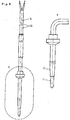
- a high-temperature sensor with a bendable measuring tip has one according to FIG. 6 or 7 bendable MI line on which a measuring tip is arranged according to FIG. 8 or 9 can be executed.
- the in FIG. 8 shown sheet resistor 1 is connected with two bonding wires to a respective coil spring, which in turn are each attached to a wire of a MI line and wrap each.
- connection between the measuring resistor chip and the supply cable is at least partially prepared by emerge between the measuring resistor and the power cable cores from a mineral-insulated feed line at the end facing the measuring resistor from the mineral insulation and electrically and mechanically connected to one spring and the springs each wound around the wires.
- a high-temperature sensor element for a temperature range from -40 ° C to 1200 ° C is created from a platinum thin-film measuring resistor on a sapphire substrate, in which connecting wires are attached as strain relief to the ceramic substrate as platinum bonding wires with a fixation drop.
- the relevant operating temperature for turbochargers is currently over 1,050 ° C.
- the sheet resistance (1) is in a casting (2) of high-purity alumina in a metal sleeve (11) made of nickel-chromium steel (alloy 602 ca) (61 wt .-% Ni, 25 wt .-% Cr, 10 wt .-% Fe and 2.2 wt .-% Al) embedded and with spring-formed 0.25 mm thick lead wires (12) made of chromium steel with 70 wt .-% iron, 25 wt .-% chromium and 5 wt .-% aluminum electrically connected to 0.6 mm thick wires (13) of the mineral insulated line (14) ( FIGS. 7 and 8 ).
- a metal sleeve (11) made of nickel-chromium steel (alloy 602 ca) (61 wt .-% Ni, 25 wt .-% Cr, 10 wt .-% Fe and 2.2 wt .-% Al) embedded and with spring-formed 0.25 mm thick
- the cores (13) of nickel-chromium steel with 80 wt .-% nickel and 20 wt .-% chromium are embedded in a highly compacted mineral powder (15), which of a protective metal shell (16) made of alloy 601 (60 wt. -% Ni, 21 wt .-% Cr, 15 wt .-% Fe and 1.2 wt .-% Al) is surrounded.
- the cores (13) of the mineral-insulated line (14) are electrically connected at their end opposite the sheet resistance (1) to 0.6 mm thick lines of the connection cable (6) ( Fig. 6 and 7 ).
- the spring-shaped lead wires (12) are plugged according to the invention as coil springs on the wires (13) of the mineral-insulated line and connected at its the sheet resistance (1) opposite end electrically connected to the wires. Since with rapid temperature changes up to the temperature of the turbocharger of 1,050 ° C, the relative change in length between the mineral insulated line (14) and the sheet resistance (1) in the metal sleeve (11) leads to breakage of conventional lead wires, according to the invention such a failure of the turbocharger protection device avoided by being on the veins guided spiral springs the various loads are significantly attenuated, in particular the loads caused by the longitudinal expansion and vibration of the vehicle.
- the cores (13) of the mineral-insulated cable are electrically connected to the spiral-shaped feeder wires (12) and restrict the movement possibilities of the feeder wire by guiding the feeder wire as a helical spring on the cores serving as axles ( Fig. 8 ). Therefore, according to the invention tearing of the lead wires is avoided in shocks and provided a high vibration protection, which only allows a sufficient life for use as a turbocharger protection device.
- the metal sleeve (11) made of nickel-chromium steel (alloy 602 approximately 61 wt .-% Ni, 25 wt .-% Cr, 10 wt .-% Fe and 2.2 wt .-% AI) is mechanically with the MI Line (14) directly connected or optionally according to Fig. 8 via an intermediate piece 17 made of the same material.
- the potting (2) of high-purity alumina (99.9%) is dosed in a metal sleeve (11) and fired.
- the potting compound sinters and fixes the sheet resistance (1).
- the version is suitable for particularly high temperature applications, in particular up to 1,200 ° C.
- the metal sleeve (11) consists of a nickel-chromium alloy with 72 wt .-% nickel, 16 wt .-% chromium and 8 wt .-% iron.
- the thermal shock resistance of the lead wires lasts 10,000, in particular according to the examples 20,000 temperature changes with temperature changes of 100 ° C to 850 ° C and a time T63 of 6 seconds, corresponding to a heating rate of 90K / sec. According to the invention, therefore, the range of thermal decoupling according to the examples is designed so that a material fatigue does not lead to failure of the system due to the temperature changes.
- the connection diagram according to Fig. 5 shows the connection of the MI cable (14) to the mass.
- a flange (9) made of the above nickel-chromium alloy serves to define an insertion depth of the measuring tip.
- a high-temperature sensor element for a temperature range of -40 ° C to 1200 ° C is created.
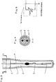
- the chip 1 is embedded in a potting 2 made of high-purity aluminum oxide and electrically connected with resiliently shaped platinum bonding wires 3 to heat-dissipating wires 4 made of chromium steel with 70% by weight iron, 25% by weight chromium and 5% by weight aluminum ( Fig. 4 ).
- the heat decoupling wires 4 are according to the invention essentially surrounded by a capillary tube 5 made of aluminum oxide ( Fig. 3 ). At its end opposite the chip 1, the heat decoupling wires 4 are connected to spirally arranged wires of the connecting cable 6 ( Fig. 1 and 2 ).
- the potting 2 is dosed and fired in a sleeve 7 made of chromium steel with 70 wt .-% iron, 25 wt .-% chromium and 5 wt .-% aluminum.
- the casting compound sinters and fixes the chip 1.
- This design is suitable for particularly high temperature applications, in particular up to 1,200 ° C.
- the sleeve 7 and the heat decoupling wires 4 made of a nickel-chromium alloy with 72 wt .-% nickel, 16 wt .-% chromium and 8 wt .-% iron.
- an additional tube 8 is partially pushed over the sleeve 7 and welded thereto.
- the additional tube 8 protects the connection of the heat decoupling wires with the connecting cable, which is sealed and fixed by means of two beads 10 in the additionally pushed tube 8.
- the thermal shock resistance of the bonding wires lasts 10,000, in particular according to the examples 20,000 temperature changes with temperature changes from 100 ° C to 850 ° C and a time t 63 of 6 sec corresponding to a heating rate of 90 K / sec. According to the invention, therefore, the range of thermal decoupling according to the examples is designed so that a material fatigue does not lead to failure of the system due to the temperature changes.
- connection diagram according to Fig. 5 shows the sleeve 7 connected to the ground.
- a flange 9 made of the above nickel-chromium alloy serves to define an insertion depth of the measuring tip.
Landscapes
- Physics & Mathematics (AREA)
- General Physics & Mathematics (AREA)
- Engineering & Computer Science (AREA)
- Chemical & Material Sciences (AREA)
- Combustion & Propulsion (AREA)
- Mechanical Engineering (AREA)
- General Engineering & Computer Science (AREA)
- Supercharger (AREA)
- Measuring Temperature Or Quantity Of Heat (AREA)
Description
- Die Erfindung betrifft eine Turbolader-Schutzeinrichtung, dafür als Bauteil geeignete Hochtemperatur-Sensorelemente und Verfahren zu deren Herstellung. Turbolader sind vor Überhitzung zu schützen, weshalb sie mit einer entsprechenden Schutzeinrichtung ausgestattet werden. Hierzu wurden Abschalteinrichtungen für Diesel-Turbolader auf 900°C bis 1.050°C und bei Benzinern bis auf 1.120°C eingestellt.
- Für Benziner sind bislang nur Thermoelemente unter Ausnutzung des Seebeck-Effekts hierfür anwendbar. Aufwendig hierfür ist die Elektronik. Bis 900°C werden Halbleiter-Temperaturelemente (NTC) mit vereinfachter Elektronik angewendet. Problematisch an der negativen Temperaturcharakteristik ist, dass bei einer Drift die Abschaltung bei zu hohen Temperaturen erfolgt und der Turbolader Schaden nimmt.
-
DE 101 58 529 offenbart einen Hochtemperatur-Sensorelement, in dem ein Messwiderstandschip in einem Verguss innerhalb eines Hüllrohres eingebrannt und mit Bonddrähten an weitere Drähte angeschlossen ist, und wobei die Drähte von einem Kapillarrohr umhüllt sind. D1 offenbart weiter mehrere Ausführungsformen mit verschiedenen alternativen Lösungen zur Abschaffung mechanischer und thermischer Belastungen. -
DE 102 36 036 offenbart einen Hochtemperatursensor mit einem Temperaturmesswiderstand auf einem Keramikplättchen, zwei Leitern und einem federnden Element, das den Widerstand mit einer mineralisolierten Zuleitung anschließt. - Es ist die Aufgabe der vorliegenden Erfindung, ein Hochtemperatur-Sensorelement für eine Turbolader-Überhitzungssicherung und eine sichere Turbolader-Überhitzungssicherung bereitzustellen, die einen geringeren elektronischen Aufwand erfordert als die Thermoelemente und die sowohl bei Temperaturen zwischen 900°C und 1.200°C, insbesondere bei 1.050°C bis 1.150°C anwendbar ist, als auch die Risiken der negativen Temperaturcharakteristik ausschaltet.
- Zur Lösung der Aufgabe wird erfindungsgemäß ein Hochtemperatur-Sensorelement gemäß Anspruch 1 definiert, der bei Vibrationen des Turboladers durch Temperaturwechsel bedingte Verschleiß durch ein besonders schonendes Abfedern der temperaturbedingten Ausdehnungsarbeit abgefedert oder teilweise in einer Isolierung verhindert. Hierzu wird die Zuleitung zu dem Messwiderstandschip entweder dadurch stabilisiert dass die Zuleitung einen mineralisolierten Zuleitungsteil umfasst, auf dessen dem Temperaturerfassungselement, insbesondere Messwiderstand, zugewandten Ende Adern aus der Isolierung ragen, auf die federnde Bonddrähte aufgesteckt sind, die die Verbindung zwischen den Adern und dem Temperaturerfassungselement, insbesondere Messwiderstand oder einem am Temperaturerfassungselement, insbesondere Messwiderstand befindlichen Anschlussdraht herstellen, wobei die Bonddrähte federnd um die Adern der mineralisolierten Zuleitung gewickelt sind. Alternativ wird erfindungsgemäß zwischen dem Messwiderstandschip und einem Anschlusskabeln ein Wärmeentkopplungsdraht an dem dem Temperaturerfassungselement, insbesondere Messwiderstandschip zugewandten Ende einseitig eingespannt und an dem anderen Ende federnd mit dem Zuleitungskabel verbunden, wobei die Wärmeentkopplungsdrähte von einem keramischen Kapillarrohr umhüllt sind und an ihrem dem Messwiderstandschip entgegen gesetzten Ende mit spiralförmigen Anschlusskabeln verbunden sind. In beiden Ausführungen führen die zwischen dem Messwiderstandschip und dem Zuleitungskabel durch Temperaturwechsel und Vibration bedingten Belastungen auf die Leiter zu keinem Verschleiß an den Leitern, da die Spannungen entweder abgefedert werden, oder im Fall der Mineralisolierung die Adern so fest eingebettet sind, dass sie keine Ausdehnungsarbeit verrichten können und ein Scheuern ausgeschlossen wird. Maßgeblich ist, dass die Federung bei Hochtemperaturbelastung ohne Resonanzschwingungen senkrecht zu der Richtung erfolgt, in der die Längenausdehnung abgefedert wird und nicht innerhalb einer hoch temperaturbelasteten Isolierung erfolgt. Deshalb erfolgt erfindungsgemäß eine Federung im Hochtemperaturbereich mit einer frei auf einer Achse geführten Feder oder eine Verlagerung der Federung außerhalb der Temperaturbelastung.
- Es wird ein Hochtemperatur-Sensorelement bereitgestellt, bei dem die Messspitze entsprechend den Anforderungen der Motorkonstruktion angepasst, insbesondere gebogen werden kann. Hierfür wird auf die Adern einer mehradrigen, insbesondere zweiadrigen, isolierten, insbesondere mineralisolierten Zuleitung erfindungsgemäß auf die aus der Isolierung ragenden Adern an dem dem Messwiderstandschip zugewandten Ende je eine Feder auf die Adern aufgesteckt, wobei die Federn jeweils elektrisch und mechanisch an einem Ende mit den Adern verbunden sind und an ihrem anderen Ende elektrisch und mechanisch mit dem Messwiderstandschip oder einem hochtemperaturbeständigen Anschlussdraht des Messwiderstandschips verbunden sind.
- Erfindungsgemäß werden einfache Hochtemperatursensoren bereitgestellt, bei denen zwischen dem Messwiderstand des Messwiderstandschips und dem Zuleitungskabel ein Wärmeentkopplungsdraht angeordnet ist, bei denen erfindungsgemäß der Wärmeentkopplungsdraht an dem dem Messwiderstandschip zugewandten Ende einseitig eingespannt ist und an dem anderen Ende federnd mit dem Zuleitungskabel verbunden ist.
- Das Hochtemperatur-Sensorelement für eine Turbolader-Überhitzungssicherung ist kombinierbar, bei dem der Messwiderstandschip in einem Verguss innerhalb eines Hüllrohres eingebrannt ist und federnd mit Bonddrähten an Wärmeentkopplungsdrähte angeschlossen ist, die aus dem Verguss führen, wobei die Wärmeentkopplungsdrähte erfindungsgemäß im Wesentlichen von einem keramischen Kapillarrohr umhüllt sind und an ihrem dem Messwiderstandschip entgegen gesetzten Ende mit einem spiralförmigen Anschlusskabel verbunden sind.
- Erfindungsgemäß entlasten beide Ausführungen die dünnen hitzebeständigen Anschlussdrähte, insbesondere Bonddrähte am Messwiderstandschip bzw. NTC-Thermistor, die üblicherweise über Pads (Kontaktfelder) die thermosensitive Einheit mit Strom versorgen.
- Diese Temperatursensoren weisen eine hervorragende Temperaturwechselbeständigkeit, insbesondere bezüglich schneller Temperaturwechsel auf, eignen sich als Hochtemperatursensoren und gestatten es, Turbolader-Überhitzungssicherungen mit einfacher Elektronik zuverlässig zu betreiben.
- Eine Turbolader-Überhitzungssicherung wird erfindungsgemäß durch den Anspruch 6 definiert, und weist ein Hochtemperatur-Sensorelement für einen Temperaturbereich von -40 bis 1.200°C auf, bei dem das Hochtemperatur-Sensorelement ein Messwiderstandschip aus einem Platindünnschicht-Messwiderstand auf elektrisch isolierendem oxidischen Substrat aufweist, das in einem keramischen Verguss eingebettet ist und mit federnd geformten Bonddrähten elektrisch auf Adern einer mineralisolierten Zuleitung erfindungsgemäß umwickelt oder an Wärmeentkopplungsdrähte angeschlossen ist, die aus dem Verguss führen und erfindungsgemäß die Wärmeentkopplungsdrähte im Wesentlichen von einem keramischen Kapillarrohr umgeben und an ihrem dem Messwiderstandschip entgegen gesetzten Ende mit spiralförmig angeordneten Anschlusskabeln verbunden sind. Statt des Kapillarrohrs können die Wärmeentkopplungsdrähte auch in einem pulverförmigen oder wollartigem dielektrischem Material wie beispielsweise Mineralwolle geführt werden.
- In einem erfindungsgemäßen Verfahren gemäß Anspruch 7 zur Herstellung eines Hochtemperatur-Sensorelements für eine Turbolader-Überhitzungssicherung, bei dem ein Messwiderstandschip in einem Verguss innerhalb eines Hüllrohres eingebrannt wird, federnd mit Bonddrähten an Adern einer mineralisolierten Zuleitung oder an Wärmeentkopplungsdrähte angeschlossen wird, die aus dem Verguss führen, werden erfindungsgemäß die Adern mit den Bonddrähten, insbesondere aus Pt oder PtRh oder Zuleitungen, insbesondere aus Chromstahl umwickelt oder die Wärmeentkopplungsdrähte im Wesentlichen von einem keramischen Kapillarrohr umhüllt und an ihrem dem Messwiderstandschip entgegen gesetzten Ende mit spiralförmigen Anschlusskabel verbunden.
- Der Verguss ist ein oxidisches Material, insbesondere keramisches Material, vorzugsweise hochreines Aluminiumoxid. Der Verguss wird in einer Hülse gebrannt. Dabei sintert die Vergussmasse und fixiert den Messwiderstandschip. Die Hülse besteht vorzugsweise aus dem gleichen Material wie die Adern oder der Wärmeentkopplungsdraht. In einer für besonders hohe Temperaturanwendungen, insbesondere zwischen 1.000°C und 1.200°C bewährten Ausführung besteht die Hülse oder die Ader oder der Wärmeentkopplungsdraht aus einer Eisen-Aluminium-Chrom-Legierung. Vorzugsweise besteht die Legierung aus 50 bis 80, insbesondere 60 bis 75 Gew.-% Fe, 15 bis 40, insbesondere 20 bis 30 Gew.-% Cr, und 5 bis 30, insbesondere 10 bis 20 Gew.-% Al.
- In einer für Temperaturanwendungen bis 1.000°C bewährten Ausführung besteht die Hülse oder die Ader oder der Wärmeentkopplungsdraht aus einer Nickel-Chrom-Legierung. Vorzugsweise besteht diese Legierung aus 60 bis 80, insbesondere 70 bis 75 Gew.-% Ni, 10 bis 25, insbesondere 15 bis 20 Gew.-% Cr, und 5 bis 10 Gew.-% Fe.
- Insbesondere weist die mineralisolierte Zuleitung zwei in Verguss eingebettete Adern auf. Analog ist es besonders zweckmäßig, je zwei Wärmeentkopplungsdrähte einseitig einzuspannen und am jeweils anderen Ende federnd mit je einer Ader des Zuleitungskabels zu verbinden. Die Federung erfolgt vorzugsweise durch eine federnde Anordnung des Kabels, insbesondere dessen Adern. Die Wärmeentkopplungsdrähte dienen als elektrischer Leiter zwischen dem heißen und dem kalten Ende der Messspitze. Die Wärmeentkopplungsdrähte sind vorzugsweise zu über 50 %, insbesondere zu 60 bis 90 % ihrer Länge in einem keramischen Kapillarrohr geführt. Die Wärmeentkopplungsdrähte sind wesentlich dicker und länger als die Bonddrähte. Bewährte Adern oder Wärmeentkopplungsdrähte sind 0,4 bis 1 mm dick, Bonddrähte oder Federn 0,1 bis 0,25 mm.
- Der Messwiderstand ist mit zwei Edelmetall aufweisenden Bonddrähten an die Federn, Adern oder Wärmeentkopplungsdrähte angeschlossen. Die Bonddrähte bestehen vorzugsweise aus Platin oder Platin-Rhodium-Legierung. Die Bonddrähte können aderseitig als Feder geformt werden. Die Federn können auch aus einem hochtemperaturbeständigen elektrischen Leiter bestehen, der an den Bonddraht oder Messwiderstandschip angeschlossen wird. Erfindungsgemäß wurde erkannt, dass bekannte Hochtemperatur-Messspitzen bei Anwendungen für Turbolader aufgrund mangelnder Temperaturwechselbeständigkeit zum Abreißen der Bonddrähte nach 1.000 bis 2.000 schnellen Temperaturwechseln führen. Es ist deshalb erfindungswesentlich, den Bereich der thermischen Entkopplung so zu gestalten, dass eine Materialermüdung aufgrund der Temperaturwechsel nicht zum Ausfall des Systems führt. Der erfindungsgemäß zugentlastete Sensor kann weiterhin vorteilhaft in dem gesamten Abgasstrang eingesetzt werden, beispielsweise als Temperatursensor für die Partikelfilterüberwachung, die Katalysatorüberwachung, insbesondere bezüglich NOx-Katalysatoren oder auch bezüglich Abgasrückführung.
- Im Folgenden wird die Erfindung anhand von Beispielen mit Bezug auf die Zeichnungen verdeutlicht.
- Fig. 1
- zeigt eine Ansicht einer Messspitze
- Fig. 2
- ist ein Längsschnitt der Messspitze aus
Fig. 1 - Fig. 3
- ist ein Querschnitt
- Fig. 4
- ist ein vergrößerter Bereich der Messspitze im Bereich des Chips
- Fig. 5
- zeigt den Anschlussplan
- Fig. 6
- zeigt eine Ansicht eines Hochtemperatursensors mit biegbarer Messspitze
- Fig. 7
- zeigt einen Schnitt eines Hochtemperatursensors gemäß
Fig. 6 - Fig. 8 und 9 6 und 7
- zeigen eine Messspitze mit einer auf eine Ader aufgesteckten Feder gemäß Fig.
- Temperatursensor, dessen Messspitze entsprechend den Anforderungen der Motorkonstruktion angepasst, insbesondere gebogen, werden kann.
- Ein Hochtemperatursensor mit biegbarer Messspitze weist eine gemäß
Figur 6 oder7 biegbare MI-Leitung auf, an der eine Messspitze angeordnet ist, die gemäßFigur 8 oder 9 ausgeführt werden kann. Der inFigur 8 dargestellte Schichtwiderstand 1 ist mit zwei Bonddrähten an je eine Spiralfeder angeschlossen, die wiederum je auf einer Ader einer MI-Leitung befestigt sind und diese jeweils umwickeln. - Hierbei wird die Verbindung zwischen dem Messwiderstandschip und dem Zuleitungskabel zumindest teilweise dadurch hergestellt, dass zwischen dem Messwiderstand und dem Zuleitungskabel Adern aus einer mineralisolierten Zuleitung an dem dem Messwiderstand zugewandten Ende aus der Mineralisolierung heraustreten und mit je einer Feder elektrisch und mechanisch verbunden sind und die Federn jeweils um die Adern gewickelt geführt sind.
- Mit einem 1.200°C resistenten Schichtwiderstand auf Basis der Broschüre "Platin Dünnschichtsensoren, die überzeugen" von der Heraeus Sensor Technology GmbH, Stand 04/2006, insbesondere nach der nicht vorveröffentlichten Patentanmeldung
DE 10 2007 046 900 A1 aus einem Platindünnschicht-Messwiderstand auf einem Saphirsubstrat, bei dem Anschlussdrähte als Platin-Bonddrähte mit einem Fixiertropfen zugentlastet am Keramiksubstrat befestigt sind, wird ein Hochtemperatur-Sensorelement für einen Temperaturbereich von -40°C bis 1.200°C geschaffen. Die maßgebliche Einsatztemperatur für Turbolader liegt derzeit bei über 1.050°C. Der Schichtwiderstand (1) wird in einem Verguss (2) aus hochreinem Aluminiumoxid in eine Metallhülse (11) aus Nickel-Chromstahl (alloy 602 ca) (61 Gew.-% Ni, 25 Gew.-% Cr, 10 Gew.-% Fe und 2,2 Gew.-% AI) eingebettet und mit zu Federn geformten 0,25 mm dicken Zuleitungsdrähten (12) aus Chromstahl mit 70 Gew.-% Eisen, 25 Gew.-% Chrom und 5 Gew.-% Aluminium elektrisch an 0,6 mm dicke Adern (13) der mineralisolierten Leitung (14) angeschlossen (Fig. 7 und 8 ). Die Adern (13) aus Nickel-Chromstahl mit 80 Gew.-% Nickel und 20 Gew.-% Chrom sind eingebettet in ein hoch verdichtetes mineralisches Pulver (15), welches von einem schützenden Metallmantel (16) aus alloy 601 (60 Gew.-% Ni, 21 Gew.-% Cr, 15 Gew.-% Fe und 1,2 Gew.-% AI) umgeben ist. Die Adern (13) der mineralisolierten Leitung (14) sind an ihrem dem Schichtwiderstand (1) entgegengesetzten Ende elektrisch mit 0,6 mm dicken Leitungen des Anschlusskabels (6) verbunden (Fig. 6 und7 ). - Die federnd geformten Zuleitungsdrähte (12) sind erfindungsgemäß als Spiralfedern auf die Adern (13) der mineralisolierten Leitung aufgesteckt und an ihrem dem Schichtwiderstand (1) entgegengesetzten Ende elektrisch mit den Adern verbunden. Da bei schnellen Temperaturwechseln bis zur Temperatur der Turbolader von 1.050°C die relative Längenänderung zwischen der mineralisolierten Leitung (14) und dem Schichtwiderstand (1) in der Metallhülse (11) zum Bruch herkömmlicher Zuleitungsdrähte führt, wird erfindungsgemäß ein derartiger Ausfall der Turbolader-Schutzeinrichtung vermieden, indem auf den Adern geführten Spiralfedern die vielfältigen Belastungen erheblich abgeschwächt werden, insbesondere die mit der Längenausdehnung und der Vibration des Fahrzeugs verursachten Belastungen.
- Die Adern (13) der mineralisolierten Leitung sind mit den spiralisch geformten Zuleitungsdrähten (12) elektrisch verbunden und schränken die Bewegungsmöglichkeiten des Zuleitungsdrahtes dadurch ein, dass der Zuleitungsdraht als Spiralfeder auf den als Achsen dienenden Adern geführt ist (
Fig. 8 ). Deshalb wird erfindungsgemäß ein Abreißen der Zuleitungsdrähte bei Erschütterungen vermieden und ein hoher Vibrationsschutz bereitgestellt, welcher für die Anwendung als Turbolader-Schutzeinrichtung erst eine ausreichende Lebensdauer ermöglicht. - Die Metallhülse (11) aus Nickel-Chromstahl (alloy 602 ca; 61 Gew.-% Ni, 25 Gew.-% Cr, 10 Gew.-% Fe und 2,2 Gew.-% AI) wird mechanisch mit der MI-Leitung (14) direkt verbunden oder gegebenenfalls gemäß
Fig. 8 über ein Zwischenstück 17 aus gleichem Material. - Der Verguss (2) aus hochreinem Aluminiumoxid (99,9 %) wird in einer Metallhülse (11) dosiert und gebrannt. Dabei sintert die Vergussmasse und fixiert den Schichtwiderstand (1). Die Ausführung ist für besonders hohe Temperaturanwendungen geeignet, insbesondere bis 1.200°C. In einer für Temperaturanwendungen bis 1.000°C bewährten Ausführung besteht die Metallhülse (11) aus einer Nickel-Chrom-Legierung mit 72 Gew.-% Nickel, 16 Gew.-% Chrom und 8 Gew.-% Eisen.
- Es hat sich bewährt, ein zusätzliches Rohr (18) teilweise über die MI-Leitung (14) zu schieben und mit dieser zu verschweißen. Das zusätzliche Rohr (18) schützt die Verbindung der Adern (13) mit dem Anschlusskabel (6), welches über zwei Sicken (10) in dem zusätzlich aufgeschobenen Rohr abgedichtet und fixiert wird. Die Messspitze ist im Bereich der MI-Leitung biegbar (
Fig. 6 ). Die Temperaturwechselbeständigkeit der Zuleitungsdrähte hält 10.000, insbesondere gemäß den Beispielen 20.000 Temperaturwechsel bei Temperaturwechseln von 100°C bis 850°C und einer Zeit T63 von 6 Sekunden, entsprechend einer Heizrate von 90K/sec aus. Erfindungsgemäß ist daher der Bereich der thermischen Entkopplung gemäß den Beispielen so gestaltet, dass eine Materialermüdung aufgrund der Temperaturwechsel nicht zum Ausfall des Systems führt. Der Anschlussplan gemäßFig. 5 zeigt den Anschluss der MI-Leitung (14) an die Masse. Ein Flansch (9) aus obiger Nickel-Chrom-Legierung dient der Festlegung einer Einführtiefe der Messspitze. - Mit einem Chip 1 aus einem Platindünnschicht-Messwiderstand auf einem Saphirsubstrat wird ein Hochtemperatur-Sensorelement für einen Temperaturbereich von -40°C bis 1.200°C geschaffen. Der Chip 1 wird in einem Verguss 2 aus hochreinem Aluminiumoxid eingebettet und mit federnd geformten Bonddrähten 3 aus Platin elektrisch an Wärmeentkopplungsdrähte 4 aus Chromstahl mit 70 Gew.-% Eisen, 25 Gew.-% Chrom und 5 Gew.-% Aluminium angeschlossen (
Fig. 4 ). Die Wärmeentkopplungsdrähte 4 sind erfindungsgemäß im Wesentlichen von einem Kapillarrohr 5 aus Aluminiumoxid umgeben (Fig. 3 ). An ihrem dem Chip 1 entgegen gesetzten Ende sind die Wärmeentkopplungsdrähte 4 mit spiralförmig angeordneten Adern des Anschlusskabels 6 verbunden (Fig. 1 und 2 ). - Der Verguss 2 wird in einer Hülse 7 aus Chromstahl mit 70 Gew.-% Eisen, 25 Gew.-% Chrom und 5 Gew.-% Aluminium dosiert und gebrannt. Dabei sintert die Vergussmasse und fixiert den Chip 1. Diese Ausführung ist für besonders hohe Temperaturanwendungen insbesondere bis 1.200°C geeignet. In einer für Temperaturanwendungen bis 1.000°C bewährten Ausführung bestehen die Hülse 7 und die Wärmeentkopplungsdrähte 4 aus einer Nickel-Chrom-Legierung mit 72 Gew.-% Nickel, 16 Gew.-% Chrom und 8 Gew.-% Eisen.
- Vorzugsweise wird ein zusätzliches Rohr 8 teilweise über die Hülse 7 geschoben und mit dieser verschweißt. Das zusätzliche Rohr 8 schützt die Verbindung der Wärmeentkopplungsdrähte mit dem Anschlusskabel, welches über zwei Sicken 10 in dem zusätzlich aufgeschobenen Rohr 8 abgedichtet und fixiert wird.
- Die Temperaturwechselbeständigkeit der Bonddrähte hält 10.000, insbesondere gemäß den Beispielen 20.000 Temperaturwechsel bei Temperaturwechseln von 100°C bis 850°C und einer Zeit t63 von 6 sec entsprechend einer Heizrate von 90 K/sec aus. Erfindungsgemäß ist daher der Bereich der thermischen Entkopplung gemäß den Beispielen so gestaltet, dass eine Materialermüdung aufgrund der Temperaturwechsel nicht zum Ausfall des Systems führt.
- Der Anschlussplan gemäß
Fig. 5 zeigt die Hülse 7 an die Masse angeschlossen. - Ein Flansch 9 aus obiger Nickel-Chrom-Legierung dient der Festlegung einer Einführtiefe der Messspitze.
Claims (7)
- Hochtemperatur-Sensorelement für eine Turbolader-Überhitzungssicherung, wobei das Hochtemperatur-Sensorelement Anschlusskabel (6, 12) aufweist, und wobei bei dem Hochtemperatur-Sensorelement ein Messwiderstandschip (1) in einem Verguss (2) innerhalb eines Hüllrohres (7, 11, 19) eingebrannt und federnd mit Bonddrähten (3) entweder an Adern (13) einer mineralisolierten Zuleitung (14) oder an Wärmeentkopplungsdrähte (4) angeschlossen ist, die aus dem Verguss (2) führen, dadurch gekennzeichnet, dass entsprechender weise entweder die Bonddrähte (3) federnd um die Adern (13) der mineralisolierten Zuleitung (14) gewickelt sind oder die Wärmeentkopplungsdrähte (4) im Wesentlichen von einem keramischen Kapillarrohr (5) umhüllt sind und an ihrem dem Messwiderstandschip (1) entgegen gesetzten Ende mit den Anschlusskabeln (6, 12) verbunden sind, wobei die Anschlusskabel (6, 12) spiralförmig sind.
- Hochtemperatur-Sensorelement nach Anspruch 1, dadurch gekennzeichnet, dass der Messwiderstandschip (1) mit zwei Edelmetall aufweisenden Bonddrähten (3) an die Adern (13) oder Wärmeentkopplungsdrähte (4) angeschlossen ist.
- Hochtemperatur-Sensorelement nach Anspruch 2, dadurch gekennzeichnet, dass die Bonddrähte (3) aus Platin oder Platin-Rhodium-Legierung bestehen.
- Hochtemperatur-Sensorelement nach einem der Ansprüche 1 bis 3, dadurch gekennzeichnet, dass entsprechender weise entweder wenigstens eine Ader (13) oder ein Wärmeentkopplungsdraht (4) aus einer Eisen-Aluminium-Chrom-Legierung besteht.
- Hochtemperatur-Sensorelement nach Anspruch 4, dadurch gekennzeichnet, dass entsprechender weise entweder wenigstens eine Ader (13) oder ein Wärmeentkopplungsdraht (4) 50 bis 80 Gew.-% Eisen, 15 bis 40 Gew.-% Aluminium und 5 bis 30 Gew.-% Chrom aufweist.
- Turbolader-Überhitzungssicherung, umfassend ein Hochtemperatur-Sensorelement nach einem der Ansprüche 1 bis 5 für einen Temperaturbereich von -40°C bis 1.200°C, bei dem das Hochtemperatur-Sensorelement den Messwiderstandschip (1) aus einem Platindünnschicht-Messwiderstand auf elektrisch isolierendem oxidischen Substrat aufweist, der in einem keramischen Verguss (2) eingebettet ist und mit federnd geformten Bonddrähten (3) elektrisch entweder an den Adern (13) oder den Wärmeentkopplungsdrähten (4) angeschlossen ist, die aus dem Verguss (2) führen, dadurch gekennzeichnet, dass entsprechender weise entweder die Bonddrähte (3) federnd um die Adern (13) gewickelt sind oder die Wärmeentkopplungsdrähte (4) im Wesentlichen von einem keramischen Kapillarrohr (5) umgeben sind und an ihrem dem Messwiderstandschip (1) entgegen gesetzten Ende mit spiralförmig angeordneten Anschlusskabel (6, 12) verbunden sind.
- Verfahren zur Herstellung eines Hochtemperatur-Sensorelements für eine Turbolader-Überhitzungssicherung, bei dem ein Messwiderstandschip (1) in einem Verguss (2) innerhalb eines Hüllrohres (7, 11, 19) eingebrannt und federnd mit Bonddrähten (3) entweder an Adern (13) einer mineralisolierten Zuleitung (14) oder an Wärmeentkopplungsdrähte (4) angeschlossen wird, die aus dem Verguss (2) führen, dadurch gekennzeichnet, dass entsprechender weise entweder die Bonddrähte (3) federnd um die Adern (13) gewickelt werden oder die Wärmeentkopplungsdrähte (4) im Wesentlichen von einem keramischen Kapillarrohr (5) umhüllt werden und an ihrem dem Messwiderstandschip (1) entgegen gesetzten Ende mit spiralförmigen Anschlusskabeln (6, 12) verbunden werden.
Applications Claiming Priority (2)
| Application Number | Priority Date | Filing Date | Title |
|---|---|---|---|
| DE102007010403.2A DE102007010403B4 (de) | 2007-03-01 | 2007-03-01 | Temperatursensor und dessen Verwendung in einer Turboladerüberhitzungssicherung |
| PCT/EP2008/000717 WO2008104259A2 (de) | 2007-03-01 | 2008-01-30 | Schutzeinrichtung für einen turbolader-temperatursensor |
Publications (2)
| Publication Number | Publication Date |
|---|---|
| EP2126529A2 EP2126529A2 (de) | 2009-12-02 |
| EP2126529B1 true EP2126529B1 (de) | 2019-03-06 |
Family
ID=39361440
Family Applications (1)
| Application Number | Title | Priority Date | Filing Date |
|---|---|---|---|
| EP08707412.6A Active EP2126529B1 (de) | 2007-03-01 | 2008-01-30 | Schutzeinrichtung für einen turbolader-temperatursensor |
Country Status (6)
| Country | Link |
|---|---|
| US (1) | US8328419B2 (de) |
| EP (1) | EP2126529B1 (de) |
| JP (1) | JP5523111B2 (de) |
| KR (1) | KR101389167B1 (de) |
| DE (1) | DE102007010403B4 (de) |
| WO (1) | WO2008104259A2 (de) |
Families Citing this family (23)
| Publication number | Priority date | Publication date | Assignee | Title |
|---|---|---|---|---|
| DE102006034181B3 (de) * | 2006-07-24 | 2008-04-03 | Siemens Ag | Temperatursensor |
| US8251579B2 (en) * | 2007-07-16 | 2012-08-28 | Rtd Company | Robust stator winding temperature sensor |
| JP4956397B2 (ja) * | 2007-12-04 | 2012-06-20 | 日本特殊陶業株式会社 | 温度センサ |
| FR2959562A1 (fr) * | 2010-04-29 | 2011-11-04 | Renault Sa | Capteur de haute temperature comportant un fil conducteur equipe d'un troncon intermediaire souple |
| WO2011146048A1 (en) * | 2010-05-18 | 2011-11-24 | Navistar Canada, Inc. | Turbo-charger bearing monitor |
| DE102010031917B3 (de) * | 2010-07-22 | 2012-02-02 | Borgwarner Beru Systems Gmbh | Temperatursensor |
| DE102010050216B4 (de) * | 2010-11-04 | 2015-01-08 | Heraeus Sensor Technology Gmbh | Turboladerüberhitzungsschutzeinrichtung und Verfahren zu ihrer Herstellung |
| JP5881726B2 (ja) * | 2010-12-02 | 2016-03-09 | ネステク ソシエテ アノニム | 飲料装置における低慣性熱センサ |
| JP5813599B2 (ja) * | 2011-09-07 | 2015-11-17 | 日本特殊陶業株式会社 | センサ及びその製造方法 |
| JP5561292B2 (ja) * | 2012-03-06 | 2014-07-30 | 株式会社デンソー | 温度センサ |
| DE102013009033A1 (de) * | 2012-07-18 | 2014-01-23 | Tesona Gmbh & Co. Kg | Hochtemperaturmesssensoranordnung |
| WO2014182745A2 (en) * | 2013-05-07 | 2014-11-13 | Stoneridge, Inc. | Exhaust gas temperature sensor |
| US9523650B2 (en) * | 2013-09-06 | 2016-12-20 | Conax Technologies Llc | Spring loaded exhaust gas temperature sensor assembly |
| EP3112830B1 (de) | 2015-07-01 | 2018-08-22 | Sensata Technologies, Inc. | Temperatursensor und verfahren zur herstellung eines temperatursensors |
| DE102015223638A1 (de) * | 2015-11-30 | 2017-06-01 | Robert Bosch Gmbh | Sensorelement zur Erfassung mindestens einer Eigenschaft eines Messgases in einem Messgasraum und Verfahren zur Herstellung desselben |
| DE102016111736B4 (de) * | 2016-06-27 | 2020-06-18 | Heraeus Nexensos Gmbh | Hülse zur Abdeckung eines Temperatursensors, Temperaturmessvorrichtung mit einer derartigen Hülse, Verfahren zum Verbinden einer derartigen Hülse mit einer Temperaturmessvorrichtung und Verwendung einer Legierung |
| DE102016111738A1 (de) * | 2016-06-27 | 2017-12-28 | Heraeus Sensor Technology Gmbh | Kabel zum Kontaktieren eines Sensors, Temperaturmessvorrichtung, Verfahren zum Verbinden eines Kabels mit einer Temperaturmessvorrichtung und Verwendung einer Legierung zur Herstellung eines Kabels |
| DE102016118595B4 (de) * | 2016-09-30 | 2018-07-26 | Heraeus Sensor Technology Gmbh | Kabel, Temperaturmessvorrichtung und Verfahren zum Herstellen eines Kabels |
| US10428716B2 (en) | 2016-12-20 | 2019-10-01 | Sensata Technologies, Inc. | High-temperature exhaust sensor |
| US10502641B2 (en) | 2017-05-18 | 2019-12-10 | Sensata Technologies, Inc. | Floating conductor housing |
| DE102018133502A1 (de) * | 2018-12-21 | 2020-06-25 | Tdk Electronics Ag | Temperatursensorvorrichtung für hohe Temperaturen |
| DE102020116018A1 (de) * | 2020-06-17 | 2021-12-23 | Tdk Electronics Ag | Sensor |
| US12487134B2 (en) * | 2021-02-05 | 2025-12-02 | Sensata Technologies, Inc. | System and method for improving temperature detectors using expansion/contraction devices |
Family Cites Families (21)
| Publication number | Priority date | Publication date | Assignee | Title |
|---|---|---|---|---|
| DD72602A1 (de) * | 1969-02-26 | 1970-04-20 | Thermoelement mit umhüllendem Schutzrohr als Temperaturmeßglied für Regelzwecke mit geringer Anzeigeverzogerung, insbesondere zur Temperaturregelung von Gasturbinen | |
| US4265117A (en) * | 1979-01-26 | 1981-05-05 | Thoma Paul E | Surface temperature detecting apparatus |
| US4453835A (en) * | 1982-05-03 | 1984-06-12 | Clawson Burrell E | Temperature sensor |
| JPH01312432A (ja) * | 1988-06-10 | 1989-12-18 | Terumo Corp | 測温用プローブ及びその製法 |
| US4966469A (en) * | 1990-01-02 | 1990-10-30 | Fts Systems, Inc. | Positioning device for temperature sensor in freeze drying |
| JP2601046B2 (ja) * | 1991-04-19 | 1997-04-16 | 三菱電機株式会社 | 温度センサ |
| JPH05340823A (ja) * | 1992-06-11 | 1993-12-24 | Matsushita Electric Ind Co Ltd | 温度センサ |
| JP2879402B2 (ja) * | 1993-07-09 | 1999-04-05 | 株式会社生方製作所 | 密閉形感熱装置 |
| DE4328197A1 (de) * | 1993-08-21 | 1995-02-23 | Vdo Schindling | Massefreier Temperaturgeber |
| US5743251A (en) * | 1996-05-15 | 1998-04-28 | Philip Morris Incorporated | Aerosol and a method and apparatus for generating an aerosol |
| JPH1114469A (ja) * | 1997-06-25 | 1999-01-22 | Ooizumi Seisakusho:Kk | センサホルダ及び複合センサ |
| JPH11218449A (ja) * | 1997-11-21 | 1999-08-10 | Denso Corp | 温度センサ及びその製造方法 |
| US6257758B1 (en) * | 1998-10-09 | 2001-07-10 | Claud S. Gordon Company | Surface temperature sensor |
| TW463184B (en) * | 1999-04-09 | 2001-11-11 | Murata Manufacturing Co | Temperature sensor, method of producing same and method of mounting same to a circuit board |
| JP4147740B2 (ja) * | 2000-11-30 | 2008-09-10 | 株式会社デンソー | 温度センサ |
| DE10222499A1 (de) * | 2002-05-22 | 2003-12-11 | Bosch Gmbh Robert | Verfahren zur Herstellung eines Bauteils, insbesondere eines thermischen Sensors, sowie thermischer Sensor |
| DE10236036B4 (de) * | 2002-08-06 | 2006-02-02 | Temperaturmeßtechnik Geraberg GmbH | Hochtemperatursensor |
| TW557352B (en) * | 2002-10-07 | 2003-10-11 | Actherm Inc | Electronic clinical thermometer with rapid response |
| WO2005075949A1 (de) * | 2004-02-09 | 2005-08-18 | Temperaturmesstechnik Geraberg Gmbh | Hochtemperatursensor |
| DE102006034246B3 (de) * | 2006-07-21 | 2007-11-22 | Beru Ag | Temperaturfühler für ein Widerstandsthermometer, insbesondere zur Verwendung im Abgasstrang von Verbrennungsmotoren |
| DE102007011535B4 (de) * | 2006-08-21 | 2009-08-06 | Ust Umweltsensortechnik Gmbh | Hochtemperatursensor |
-
2007
- 2007-03-01 DE DE102007010403.2A patent/DE102007010403B4/de not_active Expired - Fee Related
-
2008
- 2008-01-30 JP JP2009551107A patent/JP5523111B2/ja active Active
- 2008-01-30 US US12/529,484 patent/US8328419B2/en not_active Expired - Fee Related
- 2008-01-30 EP EP08707412.6A patent/EP2126529B1/de active Active
- 2008-01-30 WO PCT/EP2008/000717 patent/WO2008104259A2/de not_active Ceased
- 2008-01-30 KR KR1020097018089A patent/KR101389167B1/ko not_active Expired - Fee Related
Non-Patent Citations (1)
| Title |
|---|
| None * |
Also Published As
| Publication number | Publication date |
|---|---|
| JP5523111B2 (ja) | 2014-06-18 |
| DE102007010403A1 (de) | 2008-09-04 |
| KR20090127880A (ko) | 2009-12-14 |
| JP2010520443A (ja) | 2010-06-10 |
| US20100091817A1 (en) | 2010-04-15 |
| WO2008104259A3 (de) | 2008-10-16 |
| DE102007010403B4 (de) | 2016-02-11 |
| US8328419B2 (en) | 2012-12-11 |
| KR101389167B1 (ko) | 2014-04-24 |
| WO2008104259A2 (de) | 2008-09-04 |
| EP2126529A2 (de) | 2009-12-02 |
Similar Documents
| Publication | Publication Date | Title |
|---|---|---|
| EP2126529A2 (de) | Schutzeinrichtung für einen turbolader-temperatursensor | |
| DE102010050216B4 (de) | Turboladerüberhitzungsschutzeinrichtung und Verfahren zu ihrer Herstellung | |
| EP2875324B1 (de) | Temperaturfühler für schnelle temperaturwechsel | |
| DE19946453B4 (de) | Temperatursensor | |
| EP1881308A1 (de) | Temperaturefühler für ein Widerstandsthermometer, insbesondere zur Verwendung im Abgasstrang von Verbrennungsmotoren | |
| DE102006034246B3 (de) | Temperaturfühler für ein Widerstandsthermometer, insbesondere zur Verwendung im Abgasstrang von Verbrennungsmotoren | |
| DE102011083437B4 (de) | Universelles Hochtemperaturelement | |
| JP2010520443A5 (de) | ||
| EP2591318B1 (de) | Messaufnehmer eines thermischen durchflussmessgeräts zur ermittlung des durchflusses eines mediums durch ein messrohr und verfahren zu dessen herstellung | |
| DE2828102C2 (de) | ||
| DE10236036B4 (de) | Hochtemperatursensor | |
| EP2895830A2 (de) | Verfahren zum verpressen oder verschweissen der schutzkappe eines hochtemperatursensors | |
| EP3997313A1 (de) | Elektrische stromdurchführung | |
| DE4330447C2 (de) | Temperatur-Sensor mit einem Meßwiderstand in einem Metallmantel | |
| DE202008016201U1 (de) | Hochtemperaturthermoelement | |
| CN109000814B (zh) | 浮动导体封装 | |
| WO1996011329A1 (de) | Elektrisch beheizbarer starterkat | |
| DE112015004970T5 (de) | Temperatursensor | |
| WO2014041168A2 (de) | Hochtemperatursensor mit schutzrohr im kalten abschnitt | |
| WO2013007648A2 (de) | Hochtemperaturmesssensoranordnung | |
| DE102009008572A1 (de) | Geschlossener Temperatursensor mit hoher Ansprechgeschwindigkeit | |
| DE102008052973A1 (de) | Elektrisches Anschlusselement für Sensoren | |
| DE20216451U1 (de) | Leitungselement für Abgase | |
| DE102013006085A1 (de) | Sensor zum Erfassen einer Temperatur, insbesondere einer Temperatur von Abgas |
Legal Events
| Date | Code | Title | Description |
|---|---|---|---|
| PUAI | Public reference made under article 153(3) epc to a published international application that has entered the european phase |
Free format text: ORIGINAL CODE: 0009012 |
|
| 17P | Request for examination filed |
Effective date: 20090724 |
|
| AK | Designated contracting states |
Kind code of ref document: A2 Designated state(s): AT BE BG CH CY CZ DE DK EE ES FI FR GB GR HR HU IE IS IT LI LT LU LV MC MT NL NO PL PT RO SE SI SK TR |
|
| 17Q | First examination report despatched |
Effective date: 20091222 |
|
| DAX | Request for extension of the european patent (deleted) | ||
| STAA | Information on the status of an ep patent application or granted ep patent |
Free format text: STATUS: EXAMINATION IS IN PROGRESS |
|
| GRAP | Despatch of communication of intention to grant a patent |
Free format text: ORIGINAL CODE: EPIDOSNIGR1 |
|
| STAA | Information on the status of an ep patent application or granted ep patent |
Free format text: STATUS: GRANT OF PATENT IS INTENDED |
|
| INTG | Intention to grant announced |
Effective date: 20181022 |
|
| GRAS | Grant fee paid |
Free format text: ORIGINAL CODE: EPIDOSNIGR3 |
|
| GRAA | (expected) grant |
Free format text: ORIGINAL CODE: 0009210 |
|
| STAA | Information on the status of an ep patent application or granted ep patent |
Free format text: STATUS: THE PATENT HAS BEEN GRANTED |
|
| AK | Designated contracting states |
Kind code of ref document: B1 Designated state(s): AT BE BG CH CY CZ DE DK EE ES FI FR GB GR HR HU IE IS IT LI LT LU LV MC MT NL NO PL PT RO SE SI SK TR |
|
| REG | Reference to a national code |
Ref country code: GB Ref legal event code: FG4D Free format text: NOT ENGLISH |
|
| REG | Reference to a national code |
Ref country code: AT Ref legal event code: REF Ref document number: 1105185 Country of ref document: AT Kind code of ref document: T Effective date: 20190315 Ref country code: CH Ref legal event code: EP |
|
| REG | Reference to a national code |
Ref country code: DE Ref legal event code: R096 Ref document number: 502008016630 Country of ref document: DE |
|
| REG | Reference to a national code |
Ref country code: IE Ref legal event code: FG4D Free format text: LANGUAGE OF EP DOCUMENT: GERMAN |
|
| RAP2 | Party data changed (patent owner data changed or rights of a patent transferred) |
Owner name: HERAEUS NEXENSOS GMBH |
|
| REG | Reference to a national code |
Ref country code: NL Ref legal event code: MP Effective date: 20190306 |
|
| REG | Reference to a national code |
Ref country code: LT Ref legal event code: MG4D |
|
| PG25 | Lapsed in a contracting state [announced via postgrant information from national office to epo] |
Ref country code: NO Free format text: LAPSE BECAUSE OF FAILURE TO SUBMIT A TRANSLATION OF THE DESCRIPTION OR TO PAY THE FEE WITHIN THE PRESCRIBED TIME-LIMIT Effective date: 20190606 Ref country code: SE Free format text: LAPSE BECAUSE OF FAILURE TO SUBMIT A TRANSLATION OF THE DESCRIPTION OR TO PAY THE FEE WITHIN THE PRESCRIBED TIME-LIMIT Effective date: 20190306 Ref country code: LT Free format text: LAPSE BECAUSE OF FAILURE TO SUBMIT A TRANSLATION OF THE DESCRIPTION OR TO PAY THE FEE WITHIN THE PRESCRIBED TIME-LIMIT Effective date: 20190306 Ref country code: FI Free format text: LAPSE BECAUSE OF FAILURE TO SUBMIT A TRANSLATION OF THE DESCRIPTION OR TO PAY THE FEE WITHIN THE PRESCRIBED TIME-LIMIT Effective date: 20190306 |
|
| PG25 | Lapsed in a contracting state [announced via postgrant information from national office to epo] |
Ref country code: NL Free format text: LAPSE BECAUSE OF FAILURE TO SUBMIT A TRANSLATION OF THE DESCRIPTION OR TO PAY THE FEE WITHIN THE PRESCRIBED TIME-LIMIT Effective date: 20190306 Ref country code: LV Free format text: LAPSE BECAUSE OF FAILURE TO SUBMIT A TRANSLATION OF THE DESCRIPTION OR TO PAY THE FEE WITHIN THE PRESCRIBED TIME-LIMIT Effective date: 20190306 Ref country code: HR Free format text: LAPSE BECAUSE OF FAILURE TO SUBMIT A TRANSLATION OF THE DESCRIPTION OR TO PAY THE FEE WITHIN THE PRESCRIBED TIME-LIMIT Effective date: 20190306 Ref country code: BG Free format text: LAPSE BECAUSE OF FAILURE TO SUBMIT A TRANSLATION OF THE DESCRIPTION OR TO PAY THE FEE WITHIN THE PRESCRIBED TIME-LIMIT Effective date: 20190606 Ref country code: GR Free format text: LAPSE BECAUSE OF FAILURE TO SUBMIT A TRANSLATION OF THE DESCRIPTION OR TO PAY THE FEE WITHIN THE PRESCRIBED TIME-LIMIT Effective date: 20190607 |
|
| PG25 | Lapsed in a contracting state [announced via postgrant information from national office to epo] |
Ref country code: EE Free format text: LAPSE BECAUSE OF FAILURE TO SUBMIT A TRANSLATION OF THE DESCRIPTION OR TO PAY THE FEE WITHIN THE PRESCRIBED TIME-LIMIT Effective date: 20190306 Ref country code: PT Free format text: LAPSE BECAUSE OF FAILURE TO SUBMIT A TRANSLATION OF THE DESCRIPTION OR TO PAY THE FEE WITHIN THE PRESCRIBED TIME-LIMIT Effective date: 20190706 Ref country code: ES Free format text: LAPSE BECAUSE OF FAILURE TO SUBMIT A TRANSLATION OF THE DESCRIPTION OR TO PAY THE FEE WITHIN THE PRESCRIBED TIME-LIMIT Effective date: 20190306 Ref country code: CZ Free format text: LAPSE BECAUSE OF FAILURE TO SUBMIT A TRANSLATION OF THE DESCRIPTION OR TO PAY THE FEE WITHIN THE PRESCRIBED TIME-LIMIT Effective date: 20190306 Ref country code: IT Free format text: LAPSE BECAUSE OF FAILURE TO SUBMIT A TRANSLATION OF THE DESCRIPTION OR TO PAY THE FEE WITHIN THE PRESCRIBED TIME-LIMIT Effective date: 20190306 Ref country code: RO Free format text: LAPSE BECAUSE OF FAILURE TO SUBMIT A TRANSLATION OF THE DESCRIPTION OR TO PAY THE FEE WITHIN THE PRESCRIBED TIME-LIMIT Effective date: 20190306 Ref country code: SK Free format text: LAPSE BECAUSE OF FAILURE TO SUBMIT A TRANSLATION OF THE DESCRIPTION OR TO PAY THE FEE WITHIN THE PRESCRIBED TIME-LIMIT Effective date: 20190306 |
|
| REG | Reference to a national code |
Ref country code: DE Ref legal event code: R082 Ref document number: 502008016630 Country of ref document: DE Representative=s name: BRAND, NORMEN, DR. RER. NAT., DE Ref country code: DE Ref legal event code: R082 Ref document number: 502008016630 Country of ref document: DE Representative=s name: BRAND, NORMEN, DIPL.-CHEM. UNIV. DR. RER. NAT., DE |
|
| PG25 | Lapsed in a contracting state [announced via postgrant information from national office to epo] |
Ref country code: PL Free format text: LAPSE BECAUSE OF FAILURE TO SUBMIT A TRANSLATION OF THE DESCRIPTION OR TO PAY THE FEE WITHIN THE PRESCRIBED TIME-LIMIT Effective date: 20190306 |
|
| REG | Reference to a national code |
Ref country code: DE Ref legal event code: R097 Ref document number: 502008016630 Country of ref document: DE |
|
| PG25 | Lapsed in a contracting state [announced via postgrant information from national office to epo] |
Ref country code: IS Free format text: LAPSE BECAUSE OF FAILURE TO SUBMIT A TRANSLATION OF THE DESCRIPTION OR TO PAY THE FEE WITHIN THE PRESCRIBED TIME-LIMIT Effective date: 20190706 |
|
| PLBE | No opposition filed within time limit |
Free format text: ORIGINAL CODE: 0009261 |
|
| STAA | Information on the status of an ep patent application or granted ep patent |
Free format text: STATUS: NO OPPOSITION FILED WITHIN TIME LIMIT |
|
| PG25 | Lapsed in a contracting state [announced via postgrant information from national office to epo] |
Ref country code: DK Free format text: LAPSE BECAUSE OF FAILURE TO SUBMIT A TRANSLATION OF THE DESCRIPTION OR TO PAY THE FEE WITHIN THE PRESCRIBED TIME-LIMIT Effective date: 20190306 |
|
| 26N | No opposition filed |
Effective date: 20191209 |
|
| PG25 | Lapsed in a contracting state [announced via postgrant information from national office to epo] |
Ref country code: SI Free format text: LAPSE BECAUSE OF FAILURE TO SUBMIT A TRANSLATION OF THE DESCRIPTION OR TO PAY THE FEE WITHIN THE PRESCRIBED TIME-LIMIT Effective date: 20190306 |
|
| PG25 | Lapsed in a contracting state [announced via postgrant information from national office to epo] |
Ref country code: TR Free format text: LAPSE BECAUSE OF FAILURE TO SUBMIT A TRANSLATION OF THE DESCRIPTION OR TO PAY THE FEE WITHIN THE PRESCRIBED TIME-LIMIT Effective date: 20190306 |
|
| PGFP | Annual fee paid to national office [announced via postgrant information from national office to epo] |
Ref country code: GB Payment date: 20200124 Year of fee payment: 13 Ref country code: DE Payment date: 20200121 Year of fee payment: 13 |
|
| PGFP | Annual fee paid to national office [announced via postgrant information from national office to epo] |
Ref country code: FR Payment date: 20200121 Year of fee payment: 13 |
|
| PG25 | Lapsed in a contracting state [announced via postgrant information from national office to epo] |
Ref country code: MC Free format text: LAPSE BECAUSE OF FAILURE TO SUBMIT A TRANSLATION OF THE DESCRIPTION OR TO PAY THE FEE WITHIN THE PRESCRIBED TIME-LIMIT Effective date: 20190306 |
|
| REG | Reference to a national code |
Ref country code: CH Ref legal event code: PL |
|
| REG | Reference to a national code |
Ref country code: BE Ref legal event code: MM Effective date: 20200131 |
|
| PG25 | Lapsed in a contracting state [announced via postgrant information from national office to epo] |
Ref country code: LU Free format text: LAPSE BECAUSE OF NON-PAYMENT OF DUE FEES Effective date: 20200130 |
|
| PG25 | Lapsed in a contracting state [announced via postgrant information from national office to epo] |
Ref country code: LI Free format text: LAPSE BECAUSE OF NON-PAYMENT OF DUE FEES Effective date: 20200131 Ref country code: CH Free format text: LAPSE BECAUSE OF NON-PAYMENT OF DUE FEES Effective date: 20200131 Ref country code: BE Free format text: LAPSE BECAUSE OF NON-PAYMENT OF DUE FEES Effective date: 20200131 |
|
| PG25 | Lapsed in a contracting state [announced via postgrant information from national office to epo] |
Ref country code: IE Free format text: LAPSE BECAUSE OF NON-PAYMENT OF DUE FEES Effective date: 20200130 |
|
| REG | Reference to a national code |
Ref country code: AT Ref legal event code: MM01 Ref document number: 1105185 Country of ref document: AT Kind code of ref document: T Effective date: 20200130 |
|
| PG25 | Lapsed in a contracting state [announced via postgrant information from national office to epo] |
Ref country code: AT Free format text: LAPSE BECAUSE OF NON-PAYMENT OF DUE FEES Effective date: 20200130 |
|
| REG | Reference to a national code |
Ref country code: DE Ref legal event code: R119 Ref document number: 502008016630 Country of ref document: DE |
|
| GBPC | Gb: european patent ceased through non-payment of renewal fee |
Effective date: 20210130 |
|
| PG25 | Lapsed in a contracting state [announced via postgrant information from national office to epo] |
Ref country code: FR Free format text: LAPSE BECAUSE OF NON-PAYMENT OF DUE FEES Effective date: 20210131 |
|
| PG25 | Lapsed in a contracting state [announced via postgrant information from national office to epo] |
Ref country code: GB Free format text: LAPSE BECAUSE OF NON-PAYMENT OF DUE FEES Effective date: 20210130 Ref country code: DE Free format text: LAPSE BECAUSE OF NON-PAYMENT OF DUE FEES Effective date: 20210803 |
|
| PG25 | Lapsed in a contracting state [announced via postgrant information from national office to epo] |
Ref country code: MT Free format text: LAPSE BECAUSE OF FAILURE TO SUBMIT A TRANSLATION OF THE DESCRIPTION OR TO PAY THE FEE WITHIN THE PRESCRIBED TIME-LIMIT Effective date: 20190306 Ref country code: CY Free format text: LAPSE BECAUSE OF FAILURE TO SUBMIT A TRANSLATION OF THE DESCRIPTION OR TO PAY THE FEE WITHIN THE PRESCRIBED TIME-LIMIT Effective date: 20190306 |