EP2126154B1 - Beschichtung für gasturbinenbauteile sowie verfahren zur bereitstellung einer beschichtung - Google Patents
Beschichtung für gasturbinenbauteile sowie verfahren zur bereitstellung einer beschichtung Download PDFInfo
- Publication number
- EP2126154B1 EP2126154B1 EP08706890A EP08706890A EP2126154B1 EP 2126154 B1 EP2126154 B1 EP 2126154B1 EP 08706890 A EP08706890 A EP 08706890A EP 08706890 A EP08706890 A EP 08706890A EP 2126154 B1 EP2126154 B1 EP 2126154B1
- Authority
- EP
- European Patent Office
- Prior art keywords
- coating
- phase
- weight
- outer layer
- proportion
- Prior art date
- Legal status (The legal status is an assumption and is not a legal conclusion. Google has not performed a legal analysis and makes no representation as to the accuracy of the status listed.)
- Not-in-force
Links
- 238000000576 coating method Methods 0.000 title claims abstract description 103
- 239000011248 coating agent Substances 0.000 title claims abstract description 76
- 238000000034 method Methods 0.000 title claims description 23
- 229910000601 superalloy Inorganic materials 0.000 claims abstract description 9
- 239000007789 gas Substances 0.000 claims description 22
- 229910052751 metal Inorganic materials 0.000 claims description 21
- 239000002184 metal Substances 0.000 claims description 21
- 238000006243 chemical reaction Methods 0.000 claims description 16
- 150000002366 halogen compounds Chemical class 0.000 claims description 15
- 229910052736 halogen Inorganic materials 0.000 claims description 13
- 150000002367 halogens Chemical class 0.000 claims description 13
- 239000002245 particle Substances 0.000 claims description 6
- 229910001092 metal group alloy Inorganic materials 0.000 claims description 4
- KRHYYFGTRYWZRS-UHFFFAOYSA-N Fluorane Chemical compound F KRHYYFGTRYWZRS-UHFFFAOYSA-N 0.000 claims description 2
- VEXZGXHMUGYJMC-UHFFFAOYSA-N Hydrochloric acid Chemical compound Cl VEXZGXHMUGYJMC-UHFFFAOYSA-N 0.000 claims description 2
- 239000012535 impurity Substances 0.000 claims 2
- 229910000041 hydrogen chloride Inorganic materials 0.000 claims 1
- IXCSERBJSXMMFS-UHFFFAOYSA-N hydrogen chloride Substances Cl.Cl IXCSERBJSXMMFS-UHFFFAOYSA-N 0.000 claims 1
- 229910000040 hydrogen fluoride Inorganic materials 0.000 claims 1
- 229910000943 NiAl Inorganic materials 0.000 abstract description 12
- 239000010410 layer Substances 0.000 description 25
- 239000000463 material Substances 0.000 description 18
- 238000009792 diffusion process Methods 0.000 description 11
- KDLHZDBZIXYQEI-UHFFFAOYSA-N palladium Substances [Pd] KDLHZDBZIXYQEI-UHFFFAOYSA-N 0.000 description 11
- BASFCYQUMIYNBI-UHFFFAOYSA-N platinum Substances [Pt] BASFCYQUMIYNBI-UHFFFAOYSA-N 0.000 description 11
- 230000000694 effects Effects 0.000 description 7
- 229910045601 alloy Inorganic materials 0.000 description 6
- 239000000956 alloy Substances 0.000 description 6
- 239000011651 chromium Substances 0.000 description 6
- 238000005260 corrosion Methods 0.000 description 6
- 230000007797 corrosion Effects 0.000 description 6
- 230000003647 oxidation Effects 0.000 description 6
- 238000007254 oxidation reaction Methods 0.000 description 6
- 238000000926 separation method Methods 0.000 description 6
- VYZAMTAEIAYCRO-UHFFFAOYSA-N Chromium Chemical compound [Cr] VYZAMTAEIAYCRO-UHFFFAOYSA-N 0.000 description 5
- 229910052782 aluminium Inorganic materials 0.000 description 5
- XAGFODPZIPBFFR-UHFFFAOYSA-N aluminium Chemical compound [Al] XAGFODPZIPBFFR-UHFFFAOYSA-N 0.000 description 5
- 229910052804 chromium Inorganic materials 0.000 description 5
- PXHVJJICTQNCMI-UHFFFAOYSA-N nickel Substances [Ni] PXHVJJICTQNCMI-UHFFFAOYSA-N 0.000 description 5
- 229910052763 palladium Inorganic materials 0.000 description 5
- 229910052697 platinum Inorganic materials 0.000 description 5
- 229910052710 silicon Inorganic materials 0.000 description 5
- 239000010703 silicon Substances 0.000 description 5
- 238000005275 alloying Methods 0.000 description 4
- 230000035945 sensitivity Effects 0.000 description 4
- 239000012190 activator Substances 0.000 description 3
- XUIMIQQOPSSXEZ-UHFFFAOYSA-N Silicon Chemical compound [Si] XUIMIQQOPSSXEZ-UHFFFAOYSA-N 0.000 description 2
- 229910000831 Steel Inorganic materials 0.000 description 2
- RTAQQCXQSZGOHL-UHFFFAOYSA-N Titanium Chemical compound [Ti] RTAQQCXQSZGOHL-UHFFFAOYSA-N 0.000 description 2
- 239000000460 chlorine Substances 0.000 description 2
- 239000013078 crystal Substances 0.000 description 2
- 239000002737 fuel gas Substances 0.000 description 2
- 238000001465 metallisation Methods 0.000 description 2
- 239000011241 protective layer Substances 0.000 description 2
- 239000010959 steel Substances 0.000 description 2
- 239000010936 titanium Substances 0.000 description 2
- 229910052719 titanium Inorganic materials 0.000 description 2
- ZAMOUSCENKQFHK-UHFFFAOYSA-N Chlorine atom Chemical compound [Cl] ZAMOUSCENKQFHK-UHFFFAOYSA-N 0.000 description 1
- PXGOKWXKJXAPGV-UHFFFAOYSA-N Fluorine Chemical compound FF PXGOKWXKJXAPGV-UHFFFAOYSA-N 0.000 description 1
- 230000015572 biosynthetic process Effects 0.000 description 1
- 229910052801 chlorine Inorganic materials 0.000 description 1
- 238000000354 decomposition reaction Methods 0.000 description 1
- 230000001419 dependent effect Effects 0.000 description 1
- 238000000151 deposition Methods 0.000 description 1
- 230000008021 deposition Effects 0.000 description 1
- 229910052731 fluorine Inorganic materials 0.000 description 1
- 239000011737 fluorine Substances 0.000 description 1
- 230000007774 longterm Effects 0.000 description 1
- 238000004519 manufacturing process Methods 0.000 description 1
- 229910001507 metal halide Inorganic materials 0.000 description 1
- 150000005309 metal halides Chemical class 0.000 description 1
- 229910052759 nickel Inorganic materials 0.000 description 1
- 239000011253 protective coating Substances 0.000 description 1
- 230000001681 protective effect Effects 0.000 description 1
- 239000007787 solid Substances 0.000 description 1
- 125000006850 spacer group Chemical group 0.000 description 1
- 238000005382 thermal cycling Methods 0.000 description 1
Images
Classifications
-
- C—CHEMISTRY; METALLURGY
- C23—COATING METALLIC MATERIAL; COATING MATERIAL WITH METALLIC MATERIAL; CHEMICAL SURFACE TREATMENT; DIFFUSION TREATMENT OF METALLIC MATERIAL; COATING BY VACUUM EVAPORATION, BY SPUTTERING, BY ION IMPLANTATION OR BY CHEMICAL VAPOUR DEPOSITION, IN GENERAL; INHIBITING CORROSION OF METALLIC MATERIAL OR INCRUSTATION IN GENERAL
- C23C—COATING METALLIC MATERIAL; COATING MATERIAL WITH METALLIC MATERIAL; SURFACE TREATMENT OF METALLIC MATERIAL BY DIFFUSION INTO THE SURFACE, BY CHEMICAL CONVERSION OR SUBSTITUTION; COATING BY VACUUM EVAPORATION, BY SPUTTERING, BY ION IMPLANTATION OR BY CHEMICAL VAPOUR DEPOSITION, IN GENERAL
- C23C10/00—Solid state diffusion of only metal elements or silicon into metallic material surfaces
- C23C10/02—Pretreatment of the material to be coated
-
- C—CHEMISTRY; METALLURGY
- C23—COATING METALLIC MATERIAL; COATING MATERIAL WITH METALLIC MATERIAL; CHEMICAL SURFACE TREATMENT; DIFFUSION TREATMENT OF METALLIC MATERIAL; COATING BY VACUUM EVAPORATION, BY SPUTTERING, BY ION IMPLANTATION OR BY CHEMICAL VAPOUR DEPOSITION, IN GENERAL; INHIBITING CORROSION OF METALLIC MATERIAL OR INCRUSTATION IN GENERAL
- C23C—COATING METALLIC MATERIAL; COATING MATERIAL WITH METALLIC MATERIAL; SURFACE TREATMENT OF METALLIC MATERIAL BY DIFFUSION INTO THE SURFACE, BY CHEMICAL CONVERSION OR SUBSTITUTION; COATING BY VACUUM EVAPORATION, BY SPUTTERING, BY ION IMPLANTATION OR BY CHEMICAL VAPOUR DEPOSITION, IN GENERAL
- C23C16/00—Chemical coating by decomposition of gaseous compounds, without leaving reaction products of surface material in the coating, i.e. chemical vapour deposition [CVD] processes
- C23C16/06—Chemical coating by decomposition of gaseous compounds, without leaving reaction products of surface material in the coating, i.e. chemical vapour deposition [CVD] processes characterised by the deposition of metallic material
- C23C16/08—Chemical coating by decomposition of gaseous compounds, without leaving reaction products of surface material in the coating, i.e. chemical vapour deposition [CVD] processes characterised by the deposition of metallic material from metal halides
-
- C—CHEMISTRY; METALLURGY
- C23—COATING METALLIC MATERIAL; COATING MATERIAL WITH METALLIC MATERIAL; CHEMICAL SURFACE TREATMENT; DIFFUSION TREATMENT OF METALLIC MATERIAL; COATING BY VACUUM EVAPORATION, BY SPUTTERING, BY ION IMPLANTATION OR BY CHEMICAL VAPOUR DEPOSITION, IN GENERAL; INHIBITING CORROSION OF METALLIC MATERIAL OR INCRUSTATION IN GENERAL
- C23C—COATING METALLIC MATERIAL; COATING MATERIAL WITH METALLIC MATERIAL; SURFACE TREATMENT OF METALLIC MATERIAL BY DIFFUSION INTO THE SURFACE, BY CHEMICAL CONVERSION OR SUBSTITUTION; COATING BY VACUUM EVAPORATION, BY SPUTTERING, BY ION IMPLANTATION OR BY CHEMICAL VAPOUR DEPOSITION, IN GENERAL
- C23C16/00—Chemical coating by decomposition of gaseous compounds, without leaving reaction products of surface material in the coating, i.e. chemical vapour deposition [CVD] processes
- C23C16/44—Chemical coating by decomposition of gaseous compounds, without leaving reaction products of surface material in the coating, i.e. chemical vapour deposition [CVD] processes characterised by the method of coating
- C23C16/448—Chemical coating by decomposition of gaseous compounds, without leaving reaction products of surface material in the coating, i.e. chemical vapour deposition [CVD] processes characterised by the method of coating characterised by the method used for generating reactive gas streams, e.g. by evaporation or sublimation of precursor materials
- C23C16/4488—Chemical coating by decomposition of gaseous compounds, without leaving reaction products of surface material in the coating, i.e. chemical vapour deposition [CVD] processes characterised by the method of coating characterised by the method used for generating reactive gas streams, e.g. by evaporation or sublimation of precursor materials by in situ generation of reactive gas by chemical or electrochemical reaction
-
- C—CHEMISTRY; METALLURGY
- C23—COATING METALLIC MATERIAL; COATING MATERIAL WITH METALLIC MATERIAL; CHEMICAL SURFACE TREATMENT; DIFFUSION TREATMENT OF METALLIC MATERIAL; COATING BY VACUUM EVAPORATION, BY SPUTTERING, BY ION IMPLANTATION OR BY CHEMICAL VAPOUR DEPOSITION, IN GENERAL; INHIBITING CORROSION OF METALLIC MATERIAL OR INCRUSTATION IN GENERAL
- C23C—COATING METALLIC MATERIAL; COATING MATERIAL WITH METALLIC MATERIAL; SURFACE TREATMENT OF METALLIC MATERIAL BY DIFFUSION INTO THE SURFACE, BY CHEMICAL CONVERSION OR SUBSTITUTION; COATING BY VACUUM EVAPORATION, BY SPUTTERING, BY ION IMPLANTATION OR BY CHEMICAL VAPOUR DEPOSITION, IN GENERAL
- C23C28/00—Coating for obtaining at least two superposed coatings either by methods not provided for in a single one of groups C23C2/00 - C23C26/00 or by combinations of methods provided for in subclasses C23C and C25C or C25D
- C23C28/02—Coating for obtaining at least two superposed coatings either by methods not provided for in a single one of groups C23C2/00 - C23C26/00 or by combinations of methods provided for in subclasses C23C and C25C or C25D only coatings only including layers of metallic material
- C23C28/021—Coating for obtaining at least two superposed coatings either by methods not provided for in a single one of groups C23C2/00 - C23C26/00 or by combinations of methods provided for in subclasses C23C and C25C or C25D only coatings only including layers of metallic material including at least one metal alloy layer
-
- C—CHEMISTRY; METALLURGY
- C23—COATING METALLIC MATERIAL; COATING MATERIAL WITH METALLIC MATERIAL; CHEMICAL SURFACE TREATMENT; DIFFUSION TREATMENT OF METALLIC MATERIAL; COATING BY VACUUM EVAPORATION, BY SPUTTERING, BY ION IMPLANTATION OR BY CHEMICAL VAPOUR DEPOSITION, IN GENERAL; INHIBITING CORROSION OF METALLIC MATERIAL OR INCRUSTATION IN GENERAL
- C23C—COATING METALLIC MATERIAL; COATING MATERIAL WITH METALLIC MATERIAL; SURFACE TREATMENT OF METALLIC MATERIAL BY DIFFUSION INTO THE SURFACE, BY CHEMICAL CONVERSION OR SUBSTITUTION; COATING BY VACUUM EVAPORATION, BY SPUTTERING, BY ION IMPLANTATION OR BY CHEMICAL VAPOUR DEPOSITION, IN GENERAL
- C23C28/00—Coating for obtaining at least two superposed coatings either by methods not provided for in a single one of groups C23C2/00 - C23C26/00 or by combinations of methods provided for in subclasses C23C and C25C or C25D
- C23C28/02—Coating for obtaining at least two superposed coatings either by methods not provided for in a single one of groups C23C2/00 - C23C26/00 or by combinations of methods provided for in subclasses C23C and C25C or C25D only coatings only including layers of metallic material
- C23C28/023—Coating for obtaining at least two superposed coatings either by methods not provided for in a single one of groups C23C2/00 - C23C26/00 or by combinations of methods provided for in subclasses C23C and C25C or C25D only coatings only including layers of metallic material only coatings of metal elements only
-
- C—CHEMISTRY; METALLURGY
- C23—COATING METALLIC MATERIAL; COATING MATERIAL WITH METALLIC MATERIAL; CHEMICAL SURFACE TREATMENT; DIFFUSION TREATMENT OF METALLIC MATERIAL; COATING BY VACUUM EVAPORATION, BY SPUTTERING, BY ION IMPLANTATION OR BY CHEMICAL VAPOUR DEPOSITION, IN GENERAL; INHIBITING CORROSION OF METALLIC MATERIAL OR INCRUSTATION IN GENERAL
- C23C—COATING METALLIC MATERIAL; COATING MATERIAL WITH METALLIC MATERIAL; SURFACE TREATMENT OF METALLIC MATERIAL BY DIFFUSION INTO THE SURFACE, BY CHEMICAL CONVERSION OR SUBSTITUTION; COATING BY VACUUM EVAPORATION, BY SPUTTERING, BY ION IMPLANTATION OR BY CHEMICAL VAPOUR DEPOSITION, IN GENERAL
- C23C28/00—Coating for obtaining at least two superposed coatings either by methods not provided for in a single one of groups C23C2/00 - C23C26/00 or by combinations of methods provided for in subclasses C23C and C25C or C25D
- C23C28/02—Coating for obtaining at least two superposed coatings either by methods not provided for in a single one of groups C23C2/00 - C23C26/00 or by combinations of methods provided for in subclasses C23C and C25C or C25D only coatings only including layers of metallic material
- C23C28/028—Including graded layers in composition or in physical properties, e.g. density, porosity, grain size
-
- F—MECHANICAL ENGINEERING; LIGHTING; HEATING; WEAPONS; BLASTING
- F01—MACHINES OR ENGINES IN GENERAL; ENGINE PLANTS IN GENERAL; STEAM ENGINES
- F01D—NON-POSITIVE DISPLACEMENT MACHINES OR ENGINES, e.g. STEAM TURBINES
- F01D5/00—Blades; Blade-carrying members; Heating, heat-insulating, cooling or antivibration means on the blades or the members
- F01D5/12—Blades
- F01D5/28—Selecting particular materials; Particular measures relating thereto; Measures against erosion or corrosion
- F01D5/288—Protective coatings for blades
-
- F—MECHANICAL ENGINEERING; LIGHTING; HEATING; WEAPONS; BLASTING
- F05—INDEXING SCHEMES RELATING TO ENGINES OR PUMPS IN VARIOUS SUBCLASSES OF CLASSES F01-F04
- F05D—INDEXING SCHEME FOR ASPECTS RELATING TO NON-POSITIVE-DISPLACEMENT MACHINES OR ENGINES, GAS-TURBINES OR JET-PROPULSION PLANTS
- F05D2230/00—Manufacture
- F05D2230/90—Coating; Surface treatment
-
- Y—GENERAL TAGGING OF NEW TECHNOLOGICAL DEVELOPMENTS; GENERAL TAGGING OF CROSS-SECTIONAL TECHNOLOGIES SPANNING OVER SEVERAL SECTIONS OF THE IPC; TECHNICAL SUBJECTS COVERED BY FORMER USPC CROSS-REFERENCE ART COLLECTIONS [XRACs] AND DIGESTS
- Y10—TECHNICAL SUBJECTS COVERED BY FORMER USPC
- Y10T—TECHNICAL SUBJECTS COVERED BY FORMER US CLASSIFICATION
- Y10T428/00—Stock material or miscellaneous articles
- Y10T428/12—All metal or with adjacent metals
- Y10T428/12493—Composite; i.e., plural, adjacent, spatially distinct metal components [e.g., layers, joint, etc.]
- Y10T428/12771—Transition metal-base component
- Y10T428/12861—Group VIII or IB metal-base component
- Y10T428/12944—Ni-base component
Definitions
- the invention relates to a coating according to the preamble of claim 1. Furthermore, the invention relates to a method for providing a coating according to the preamble of claim 6.
- the most important materials used today for gas turbine components are titanium base alloys, superalloys and high strength steels.
- Superalloys are understood to mean nickel-base alloys and cobalt-base alloys.
- the high-strength steels are used for shaft parts, gear parts, compressor casings and turbine casings of a gas turbine.
- Titanium based alloys are typical materials for compressor parts.
- Superalloys are suitable for the hot parts of a gas turbine and thus for high temperature applications.
- gas turbine components are provided with protective layers to protect the components from fuel gas oxidation and fuel gas corrosion.
- Diffusion coatings rely on interdiffusion of deposited elements of the coating material with superalloy elements of the device to be coated, subdividing diffusion coating processes into high activity diffusion coating processes as well as low activity diffusion coating processes.
- Coating methods known in practice have only a low separation efficiency, furthermore, the coating prepares from internal surfaces, such as e.g. of internal geometries hollow components, with the previously known coating process difficulties.
- Previously known coatings have high crack sensitivity on outboard zones, limiting the life of known coatings. There is therefore a need for new coatings having a longer service life, a process for producing such coatings with a high separation efficiency and a device for producing such a coating.
- the present invention is based on the problem to provide a novel coating and a method for providing a coating.
- the outer layer comprises 10% to 60% of the total coating, wherein the outer layer is formed essentially of a ⁇ -NiAl phase with an Al content between 23 and 35 wt .-%, wherein the inner layer 90% to 40% of Overall coating is made, and wherein the inner layer is formed essentially of a ⁇ -NiAl phase with an Al content of 5 to 15 wt .-%.
- the coating according to the invention has a relatively low sensitivity to cracks as well as good strength in HCF loads and LCF loads.
- the coating according to the invention provides effective protection of gas turbine components against hot gas oxidation as well as hot gas corrosion.
- the Al content in the ⁇ -NiAl phase of the outer layer is between 27 and 32% by weight.
- the ⁇ -NiAl phase of the outer layer furthermore comprises Cr and / or Si and / or Pt and / or Pd.
- a pressure between 30 and 1400 hPa is set in a starting phase of the coating process, wherein in the start phase of at least one offered halogen or at least one offered halogen compound and at least one offered donor metal, in particular from an offered donor metal alloy, at least metal monohalides are formed, wherein in a pressure of between 1050 and 4000 hPa is set for a coating phase of the coating process adjoining the start phase, and wherein in the coating phase at least the metal monohalides formed in the start phase are deposited on a component to be coated.
- the coating process of the invention is characterized by a high separation efficiency.
- outer surfaces and, on the other hand, inner surfaces of components to be coated can be coated equally well.
- the donors are arranged in the reaction space spaced from each other in parallel planes, such that the distance between the components to be coated and the donors is between 10 and 150 mm.
- the device enables effective and economical coating of components to be coated.
- the present invention relates to a novel coating for gas turbine components, in particular for gas turbine components made of a superalloy, for providing a protective layer against hot gas oxidation and hot gas corrosion. Furthermore, the invention relates to a method for producing such a coating.
- the coating according to the invention has an outer layer and an inner layer.
- the outer layer of the coating according to the invention makes up between 10% and 60% of the total coating, wherein the outer layer consists essentially of a ⁇ -NiAl phase with a proportion of aluminum (Al) between 23 and 35 wt .-%.
- Al aluminum
- the inner layer of the total coating makes up between 90% to 40% of the total coating, the inner layer consisting essentially of a ⁇ -NiAl phase with a proportion of aluminum of max. 15 wt .-% is formed.
- the Al content in the ⁇ -NiAl phase of the inner layer contributes in particular between 5 and 15% by weight.
- the good protection against hot gas oxidation and hot gas corrosion of the coating according to the invention is provided by the relatively high aluminum content in the outer layer of the ⁇ -NiAl phase.
- the low crack sensitivity of the coating according to the invention is ensured by the ⁇ -NiAl phase of the inner layer with the relatively small proportion of aluminum.
- the inner layer is preferably characterized by a cubic ⁇ or ⁇ 'crystal lattice corresponding to the crystal lattice structure of the base material of the component to be coated.
- a further increase in the oxidation resistance and corrosion resistance of the coating according to the invention can be achieved in that the outer layer of the coating according to the invention comprises chromium and / or silicon and / or platinum and / or palladium.
- the chromium content of the outer layer is preferably from 10 to 35% by weight, more preferably from 20 to 30% by weight.
- the proportion of silicon is between 2 and 14 wt .-%, in particular between 4 and 9 wt .-%.
- the content of platinum and / or palladium is between 10 and 40% by weight.
- the method according to the invention for providing the coating according to the invention is subdivided into at least two phases, namely a start phase and a coating phase subsequent to the start phase.
- a pressure between 30 and 1400 hPa is set, wherein in the start phase of at least one halogen or at least one offered halogen compound and at least one offered donor metal, in particular from an offered donor metal alloy, at least metal monohalides are formed.
- halogens preferably chlorine (Cl) or fluorine (F) or as halogen compounds, preferably hydrogen chloride (HCl) or hydrogen fluoride (HF) are kept ready. From the halogens or halogen compounds and the donor material metal monohalides are formed.
- a relatively low pressure is set between 20 and 1400 hPa in order to provide a higher proportion of metal monohalides in the gas phase.
- the start phase of the coating process is followed by the coating phase in which a relatively high pressure is set between 1050 and 4000 hPa.
- the base material of the component to be coated is nickel Ni.
- the relatively high pressure between 1050 and 4000 hPa in the coating phase By using the relatively high pressure between 1050 and 4000 hPa in the coating phase, the relative proportion of metal halegonides in the gas phase around the component surface can be increased.
- the relatively high pressure in the coating phase leads to a significantly higher proportion of metal deposition on the surface of the component to be coated.
- Another advantage of the relatively high pressure in the coating phase of the process according to the invention is that an increased scattering force sets in, ie. H.
- the distance of the donor material may be greater for the surface of the component to be coated with the same activity, whereby a more uniform deposition or coating of the component to be coated can be realized.
- internal surfaces of the component to be coated in particular internal geometries of cavities, can be well coated.
- Another advantage of the relatively high pressure in the coating phase lies in the long-term obtaining of a metal halide activator. Accordingly, a higher activator availability and activator residence time result, without the need to introduce additional halogens or halogen compounds. As a result, can be coated longer with higher separation efficiency.
- the reaction phase is followed by a reaction phase at a pressure of between 500 and 1400 hPa, followed by a further coating phase with a pressure between 1050 and 4000 hPa.
- thermochemical pump for the formation of the metal monohalides, which ultimately contributes to the good separation efficiency of the coating method according to the invention.
- the starting phase preferably extends over a period of time of between 5 and 60 minutes, and the coating phase following the starting phase preferably extends over a period of time between 10 and 120 minutes.
- a reaction phase which optionally follows the coating phase extends between 5 and 60 minutes, and a further coating phase optionally adjoining it extends in particular between 10 and 120 minutes.
- the inventive method is carried out at a process temperature between 900 ° and 1150 ° C, in particular at a process temperature between 940 ° and 1080 ° C.
- the temperature in the or each coating phase is preferably between 10 ° and 60 ° higher than the temperature of the respective preceding phase, ie the start phase or the reaction phase. In this way, defined diffusion profiles can be generated as a function of the different metal deposition activity in the various process phases.
- the donor metal is preferably kept at a particle size of between 2 and 20 mm, with the halogen or halogen compound being passed directly to the donor material.
- the halogen or the halogen compound flows around the donor material at a flow rate between 0.1 1 and 10 cm per second.
- the alloying of the elements chromium, silicon, platinum or palladium is preferably carried out by a pre-alloying of the outer layer by a thermal, thermochemical or physical process or by subsequent diffusion, the preference being given to the master alloy.
- a support layer of particles of the elements chromium, silicon, platinum or palladium or particles of an alloy with these elements can lead to the coating according to the invention.
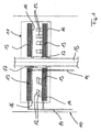
- Fig. 1 shows such a coating device 10 is highly schematic.
- the coating device 10 comprises a reaction space 11 for receiving components to be coated 12 and for receiving donors 13 from at least one donor metal, in particular a donor metal alloy.
- the donors 13 are according to Fig. 1 arranged in mutually spaced, mutually parallel planes, wherein between each two adjacent planes of donors 13 to be coated components 12 are positioned. In the exemplary embodiment of the Fig. 1 only two levels of donors 13 are shown. Up to ten levels of donors 13 may be positioned one above the other in the reaction space 11.
- the components to be coated 12 are arranged between each two levels of donors 13 in such a way that the distance between the components to be coated 12 and the donors 13 between 10 and 150 mm, preferably between 20 and 150 mm.
- the reaction space is preferably rotationally symmetrical with a diameter between 200 and 1500 mm and a height of up to 1500 mm, wherein the volume density of the donors 13 based on the total volume of the reaction space 11 is between 2% and 5%.
- Halogens or halogen compounds are conveyed via feed lines 14 in the direction of the donors 13, namely such that the halogens or halogen compounds are passed directly to the donors 13, namely solid particles of the or each donor metal. It can, how Fig. 1 shows, the supply lines 14 are introduced on the one hand from the radially outside and on the other hand from radially inward into the reaction space 11.
- the coating apparatus 10 has a centering tube 15 on which a plurality of cross members 16 engage.
- the cross member 16 serve to receive the donors 13, wherein superposed cross members 16 are spaced apart by spacers 17.
- the cross members 16 are preferably segmented viewed in the circumferential direction, with an angular pitch of between 22.5 ° and 60 °. Accordingly, viewed in the circumferential direction, each cross member 16 is subdivided into six to sixteen segments, each segment serving to receive donors 13.
- the device has a modular design and is expansion-tolerant to the effects of temperature and alloying.
- the halogens or halogen compounds are not introduced openly into the reaction space 11, but are conducted via supply lines 14 directly to the donors 13.
- the donors may be tightly closed or open-celled, with an opening ratio of between 5% and 80%.
- the donors 13 are segmented per plane with a defined angular pitch. It is also possible to arrange a plurality of annular donor segments concentric to each donor plane.
Landscapes
- Chemical & Material Sciences (AREA)
- Engineering & Computer Science (AREA)
- Materials Engineering (AREA)
- Mechanical Engineering (AREA)
- Metallurgy (AREA)
- Chemical Kinetics & Catalysis (AREA)
- Organic Chemistry (AREA)
- General Chemical & Material Sciences (AREA)
- General Engineering & Computer Science (AREA)
- Electrochemistry (AREA)
- Turbine Rotor Nozzle Sealing (AREA)
- Other Surface Treatments For Metallic Materials (AREA)
- Chemical Vapour Deposition (AREA)
- Physical Vapour Deposition (AREA)
Description
- Die Erfindung betrifft eine Beschichtung nach dem Oberbegriff des Anspruchs 1. Des Weiteren betrifft die Erfindung ein Verfahren zur Bereitstellung einer Beschichtung nach dem Oberbegriff des Anspruchs 6.
- Die wichtigsten, heutzutage für Gasturbinenbauteile verwendeten Werkstoffe sind Titanbasislegierungen, Superlegierungen und hochfeste Stähle. Unter Superlegierungen versteht man Nickelbasislegierungen und Kobaltbasislegierungen. Die hochfesten Stähle werden für Wellenteile, Getriebeteile, Verdichtergehäuse und Turbinengehäuse einer Gasturbine verwendet. Titanbasislegierungen sind typische Werkstoffe für Verdichterteile. Superlegierungen sind für die heißen Teile einer Gasturbine und damit für Hochtemperaturanwendungen geeignet.
- Bei der Verwendung in Gasturbinen sind Bauteile aus Superlegierungen Temperaturen von mehr als 1000°C, hohen Spannungen durch Fliehkräfte sowie hohen Temperaturwechselbelastungen ausgesetzt. Für Gasturbinenbauteile verwendete Superlegierungen sind typischerweise für eine gute Kombination aus Temperaturfestigkeit, Kriechfestigkeit und Dehnwechselbelastbarkeit ausgelegt. Dies erfolgt durch die Wahl geeigneter Legierungselemente und durch den Einsatz von gerichtet erstarrten bzw. einkristallin erstarrten Werkstoffen.
- Allerdings führen Maßnahmen, die der Festigkeitssteigerung eines Werkstoffs dienen, typischerweise zu einer höheren Empfindlichkeit von Oberflächen und Randschichten gegenüber Heizgasoxidation und Heizgaskorrosion. Daher werden Gasturbinenbauteile mit Schutzschichten versehen, um die Bauteile vor Heizgasoxidation und Heizgaskorrosion zu schützen.
- Zum Aufbringen von Schutzschichten auf Gasturbinenbauteile sind aus der Praxis als Beschichtungsverfahren in erster Linie Diffusionsbeschichtungsverfahren sowie Auflagebeschichtungsverfahren zum Beispiel aus
EP 1493844 A1 bekannt. Diffusionsbeschichtungen beruhen auf einer Interdiffusion von abgeschiedenen Elementen des Beschichtungswerkstoffs mit Elementen der Superlegierung des zu beschichtenden Bauteils, wobei Diffusionsbeschichtungsverfahren in Hochaktivitätsdiffusionsbeschichtungsverfahren sowie Niedrigaktivitätsdiffusionsbeschichtungsverfahren untergliedert werden. - Bei Hochaktivitätsdiffusionsbeschichtungsverfahren findet eine hohe Einwärtsdiffusion des Beschichtungswerkstoffs in den Werkstoff des zu beschichtenden Bauteils statt. Bei Niedrigaktivitätsdiffusionsbeschichtungsverfahren erfolgt hingegen eine stärkere Auswärtsdiffusion von Elementen des Werkstoffs des zu beschichtenden Bauteils in den Beschichtungswerkstoff der abgeschiedenen Beschichtung. Auflagebeschichtungsverfahren beruhen weniger auf einer Interdiffusion, vielmehr ist die Schutzwirkung der Beschichtung eine inhärente Eigenschaft des abgeschiedenen Materials oder der abgeschiedenen Materialpartikel.
- Aus der Praxis bekannte Beschichtungsverfahren verfügen lediglich über eine geringe Abscheideleistung, des Weiteren bereitet die Beschichtung von innenliegenden Oberflächen, wie z.B. von Innengeometrien hohler Bauteile, mit den bislang bekannten Beschichtungsverfahren Schwierigkeiten. Bislang bekannte Beschichtungen verfügen über eine hohe Rissempfindlichkeit an außenliegenden Zonen, wodurch die Lebensdauer bekannter Beschichtungen beschränkt wird. Es besteht daher ein Bedarf an neuen Beschichtungen mit höherer Lebensdauer, an einem Verfahren zur Herstellung solcher Beschichtungen mit hoher Abscheideleistung sowie an einer Vorrichtung zur Herstellung einer solchen Beschichtung.
- Hiervon ausgehend liegt der vorliegenden Erfindung das Problem zu Grunde, eine neuartige Beschichtung sowie ein Verfahren zur Bereitstellung einer Beschichtung zu schaffen.
- Dieses Problem wird durch eine Beschichtung gemäß Anspruch 1 gelöst. Erfindungsgemäß macht die Außenschicht 10 % bis 60 % der Gesamtbeschichtung aus, wobei die Außenschicht im wesentlichen aus einer β-NiAl-Phase mit einem Al-Anteil zwischen 23 und 35 Gew.-% gebildet ist, wobei die Innenschicht 90 % bis 40 % der Gesamtbeschichtung ausmacht, und wobei die Innenschicht im wesentlichen aus einer γ-NiAl-Phase mit einem Al-Anteil von 5 - 15 Gew.-% gebildet ist.
- Die erfindungsgemäße Beschichtung verfügt über eine relativ geringe Rissempfindlichkeit sowie über eine gute Festigkeit bei HCF-Belastungen sowie LCF-Belastungen. Die erfindungsgemäße Beschichtung stellt einen effektiven Schutz von Gasturbinenbauteilen gegenüber Heißgasoxidation sowie Heißgaskorrosion bereit.
- Vorzugsweise beträgt der Al-Anteil in der β-NiAl-Phase der Außenschicht zwischen 27 und 32 Gew.-%.
- Nach einer Weiterbildung der Erfindung umfasst die β-NiAl-Phase der Außenschicht weiterhin Cr und/oder Si und/oder Pt und/oder Pd.
- Das erfindungsgemäße Verfahren zur Bereitstellung einer Beschichtung ist in Anspruch 6 definiert. Erfindungsgemäß wird in einer Startphase des Beschichtungsverfahrens ein Druck zwischen 30 und 1400 hPa eingestellt, wobei in der Startphase aus mindestens einem angebotenen Halogen bzw. mindestens einer angebotenen Halogenverbindung und mindestens einem angebotenen Spendermetall, insbesondere aus einer angebotenen Spendermetalllegierung, zumindest Metallmonohalogenide gebildet werden, wobei in einer sich an die Startphase anschließenden Beschichtungsphase des Beschichtungsverfahrens ein Druck zwischen 1050 und 4000 hPa eingestellt wird, und wobei in der Beschichtungsphase zumindest die in der Startphase gebildeten Metallmonohalogenide auf ein zu beschichtendes Bauteil abschieden werden.
- Das erfindungsgemäße Beschichtungsverfahren zeichnet sich durch eine hohe Abscheideleistung aus. Mit dem erfindungsgemäßen Beschichtungsverfahren können einerseits außenliegende Oberflächen sowie andererseits innenliegende Oberflächen von zu beschichtenden Bauteilen gleichermaßen gut beschichtet werden.
- In der Vorrichtung zur Bereitstellung sind die zu beschichtenden Bauteile und die Donatoren im Reaktionsraum beabstandet voneinander in parallelen Ebenen angeordnet, derart, dass der Abstand zwischen den zu beschichtenden Bauteilen und den Donatoren zwischen 10 und 150 mm beträgt.
- Die Vorrichtung ermöglicht eine effektive sowie wirtschaftliche Beschichtung von zu beschichtenden Bauteilen.
- Bevorzugte Weiterbildungen der Erfindung ergeben sich aus den Unteransprüchen und der nachfolgenden Beschreibung. Ausführungsbeispiele der Erfindung werden, ohne hierauf beschränkt zu sein, an Hand der Zeichnung näher erläutert. Dabei zeigt:
- Fig. 1
- eine schematisierte Vorrichtung zur Bereitstellung einer Beschichtung.
- Die hier vorliegende Erfindung betrifft eine neue Beschichtung für Gasturbinenbauteile, insbesondere für aus einer Superlegierung hergestellte Gasturbinenbauteile, zur Bereitstellung einer Schutzschicht gegenüber Heißgasoxidation sowie Heißgaskorrosion. Weiterhin betrifft die Erfindung ein Verfahren zur Herstellung einer solchen Beschichtung.
- Die erfindungsgemäße Beschichtung verfügt über eine Außenschicht sowie eine Innenschicht. Die Außenschicht der erfindungsgemäßen Beschichtung macht zwischen 10% und 60% der Gesamtbeschichtung aus, wobei die Außenschicht im Wesentlichen aus einer β-NiAl-Phase mit einem Anteil an Aluminium (Al) zwischen 23 und 35 Gew.-% liegt. Vorzugsweise beträgt der Al-Anteil in der β-NiAl-Phase der Außenschicht zwischen 27 und 32 Gew.-%.
- Die Innenschicht der Gesamtbeschichtung macht zwischen 90% bis 40% der Gesamtbeschichtung aus, wobei die Innenschicht im Wesentlichen aus einer γ-NiAl-Phase mit einem Anteil an Aluminium von max. 15 Gew.-% gebildet ist. Der Al-Anteil in der γ-NiAl-Phase der Innenschicht trägt insbesondere zwischen 5 und 15 Gew.-%.
- Die gute Schutzeigenschaft gegenüber Heißgasoxidation sowie Heißgaskorrosion der erfindungsgemäßen Beschichtung wird durch den relativ hohen Aluminiumanteil in der Außenschicht aus der β-NiAl-Phase bereitgestellt. Die geringe Rissempfindlichkeit der erfindungsgemäßen Beschichtung wird durch die γ-NiAl-Phase der Innenschicht mit dem relativ geringen Anteil an Aluminium gewährleistet. Vorzugsweise ist die Innenschicht durch ein kubisches γ- bzw. γ'-Kristallgitter entsprechend der Kristallgitterstruktur des Grundwerkstoffs des zu beschichtenden Bauteils gekennzeichnet.
- Eine weitere Steigerung der Oxidationsbeständigkeit sowie Korrosionsbeständigkeit der erfindungsgemäßen Beschichtung kann dadurch erreicht werden, dass die Außenschicht der erfindungsgemäßen Beschichtung Chrom und/oder Silizium und/oder Platin und/oder Palladium umfasst.
- Dann, wenn die Außenschicht Chrom umfasst, beträgt der Chromanteil an der Außenschicht vorzugsweise zwischen 10 und 35 Gew.-%, insbesondere zwischen 20 und 30 Gew.-%. Dann, wenn die Außenschicht Silizium umfasst, beträgt der Anteil an Silizium zwischen 2 und 14 Gew.-%, insbesondere zwischen 4 und 9 Gew.-%. Dann, wenn die Außenschicht Platin und/oder Palladium umfasst, beträgt der Anteil an Platin und/oder Palladium zwischen 10 und 40 Gew.-%.
- Das erfindungsgemäße Verfahren zur Bereitstellung der erfindungsgemäßen Beschichtung untergliedert sich zumindest in zwei Phasen, nämlich in eine Startphase sowie eine sich an die Startphase anschließende Beschichtungsphase.
- In der Startphase des Beschichtungsverfahrens wird ein Druck zwischen 30 und 1400 hPa eingestellt, wobei in der Startphase aus mindestens einem angebotenen Halogen bzw. mindestens einer angebotenen Halogenverbindung und mindestens einem angebotenen Spendermetall, insbesondere aus einer angebotenen Spendermetalllegierung, zumindest Metallmonohalogenide gebildet werden.
- Als Halogene werden vorzugsweise Chlor (Cl) oder Fluor (F) bzw. als Halogenverbindungen vorzugsweise Wasserstoffchlorid (HCl) oder Wasserstofffluorid (HF) bereitgehalten. Aus den Halogenen bzw. Halogenverbindungen und dem Spendermaterial werden Metallmonohalogenide gebildet.
- In der Startphase des Beschichtungsverfahrens kommen in der Gasphase nach folgender Gleichung
MexHaly + zMe ↔ MeHal ; x,z=1-2 und y=2-3
sowohl Halogenverbindungen MexHaly als auch Metallmonohalegonide MeHal vor. Daher wird in der Startphase ein relativ geringer Druck zwischen 20 und 1400 hPa eingestellt, um in der Gasphase einen höheren Anteil an Metallmonohalegoniden bereitzustellen. - An die Startphase des Beschichtungsverfahrens schließt sich die Beschichtungsphase an, in der ein relativ hoher Druck zwischen 1050 und 4000 hPa eingestellt wird. In der Beschichtungsphase werden die in der Startphase bebildeten Metallmonohalegonide auf die Oberfläche des zu beschichtenden Bauteils abgeschieden, wobei hierbei die Metallmonohalegonide in einer sogenannten Zersetzungsreaktion oder Disproportionsreaktion mit dem Grundwerkstoff des zu beschichtenden Bauteils nach folgenden Gleichungen reagieren:
MeHal + Ni ↔ NiMe + MexHaly; x=2-4 und y=1-3
oder
MeHal + Ni ↔ MeHal + Hal
- In den obigen Gleichungen wurde angenommen, dass es sich beim Grundwerkstoff des zu beschichtenden Bauteils um Nickel Ni handelt.
- Es liegt demnach im Sinne des erfindungsgemäßen Verfahrens, in einer Startphase Metallmonohalegonide bei relativ geringem Druck zwischen 30 und 1400 hPa bereitzustellen und die in der Startphase bereitgestellten Metallmonohalegonide in einer nachfolgenden Beschichtungsphase bei einem relativ hohen Druck zwischen 1050 und 4000 hPa auf die Oberfläche des zu beschichtenden Bauteils abzuscheiden.
- Durch die Verwendung des relativ hohen Drucks zwischen 1050 und 4000 hPa in der Beschichtungsphase kann der relative Anteil an Metallhalegoniden in der Gasphase um die Bauteiloberfläche erhöht werden. Zum anderen führt der relativ hohe Druck in der Beschichtungsphase dazu, dass ein deutlich höherer Anteil an Metallabscheidung auf die zu beschichtende Oberfläche des Bauteils erfolgt. Ein weiterer Vorteil des relativ hohen Drucks in der Beschichtungsphase des erfindungsgemäßen Verfahrens liegt darin, dass sich eine erhöhte Streukraft einstellt, d. h. der Abstand des Spendermaterials kann zur Oberfläche des zu beschichtenden Bauteils bei gleicher Aktivität größer sein, wodurch eine gleichmäßigere Abscheidung bzw. Beschichtung des zu beschichtenden Bauteils realisiert werden kann. Durch die erhöhte Streukraft können des Weiteren innenliegende Oberflächen des zu beschichtenden Bauteils, insbesondere Innengeometrien von Hohlräumen, gut beschichtet werden. Ein weiterer Vorteil des relativ hohen Drucks in der Beschichtungsphase liegt im langandauernden Erhalt eines Metallhalegonidaktivators. Es ergibt sich demnach eine höhere Aktivatorverfügbarkeit sowie Aktivatorverweildauer, ohne dass zusätzliche Halogene bzw. Halogenverbindungen eingeleitet werden müssten. Dadurch kann mit höherer Abscheideleistung länger beschichtet werden.
- Nach einer vorteilhaften Weiterbildung des erfindungsgemäßen Beschichtungsverfahrens schließt sich an die Beschichtungsphase eine Reaktionsphase mit einem Druck zwischen 500 und 1400 hPa an, wobei sich an diese Reaktionsphase eine weitere Beschichtungsphase mit einem Druck zwischen 1050 und 4000 hPa anschließt. Hierdurch kann die Abscheideleistung des erfindungsgemäßen Beschichtungsverfahrens nochmals gesteigert bzw. erhöht werden.
- Durch die sich abwechselnden Phasen mit relativ hohen Drücken sowie relativ niedrigen Drücken wird eine Art thermochemische Pumpe zur Bildung der Metallmonohalegonide bereitgestellt, was letztendlich zu der guten Abscheideleistung des erfindungsgemäßen Beschichtungsverfahrens beiträgt.
- Die Startphase erstreckt sich vorzugsweise über eine Zeitdauer zwischen 5 und 60 min, die sich an die Startphase anschließende Beschichtungsphase erstreckt sich vorzugsweise über eine Zeitdauer zwischen 10 und 120 min. Eine sich ggf. an die Beschichtungsphase anschließende Reaktionsphase erstreckt sich zwischen 5 und 60 min, eine sich ggf. hieran anschließende weitere Beschichtungsphase erstreckt sich insbesondere zwischen 10 und 120 min.
- Das erfindungsgemäße Verfahren wird bei einer Prozesstemperatur zwischen 900° und 1150 °C, insbesondere bei einer Prozesstemperatur zwischen 940° und 1080 °C durchgeführt.
- Dabei ist die Temperatur in der oder jeder Beschichtungsphase vorzugsweise zwischen 10° und 60° höher als die Temperatur der jeweils vorausgehenden Phase, also der Startphase bzw. der Reaktionsphase. Hierdurch können definierte Diffusionsprofile in Abhängigkeit der unterschiedlichen Metallabscheideaktivität in den verschiedenen Prozessphasen erzeugt werden.
- Das Spendermetall wird vorzugsweise mit einer Partikelgröße zwischen 2 und 20 mm bereitgehalten, wobei das Halogen bzw. die Halogenverbindung direkt auf das Spendermaterial geleitet wird. Dabei umströmt vorzugsweise das Halogen bzw. die Halogenverbindung das Spendermaterial mit einer Strömungsgeschwindigkeit zwischen 0,1 1 und 10 cm pro Sekunde.
- Auf die obige Art und Weise wird insbesondere Aluminium auf das zu beschichtende Bauteil abgeschieden.
- Das Zulegieren der Elemente Chrom, Silizium, Platin bzw. Palladium erfolgt vorzugsweise durch eine Vorlegierung der Außenschicht mit einem thermischen, thermochemischen oder physikalischen Verfahren oder durch nachträgliches Eindiffundieren, wobei der Vorlegierung der Vorzug gegeben wird.
- Auch ein Überalitieren einer Auflageschicht aus Partikeln der Elemente Chrom, Silizium, Platin bzw. Palladium oder Partikel aus einer Legierung mit diesen Elementen kann zu der erfindungsgemäßen Beschichtung führen.
- Das erfindungsgemäße Verfahren zur Bereitstellung der erfindungsgemäßen Beschichtung wird in einer speziellen Vorrichtung durchgeführt, die eine wirtschaftliche Beschichtung zu beschichtender Bauteile ermöglicht.
Fig. 1 zeigt eine solche Beschichtungsvorrichtung 10 stark schematisiert. - So umfasst die Beschichtungsvorrichtung 10 einen Reaktionsraum 11 zur Aufnahme zu beschichtender Bauteile 12 sowie zur Aufnahme von Donatoren 13 aus mindestens einem Spendermetall, insbesondere einer Spendermetalllegierung. Dabei sind die Donatoren 13 gemäß
Fig. 1 in voneinander beabstandeten, parallel zueinander verlaufenden Ebenen angeordnet, wobei zwischen jeweils zwei benachbarten Ebenen aus Donatoren 13 zu beschichtende Bauteile 12 positioniert sind. Im Ausfiihrungsbeispiel derFig. 1 sind lediglich zwei Ebenen aus Donatoren 13 dargestellt. Es können bis zu zehn Ebenen von Donatoren 13 übereinander im Reaktionsraum 11 positioniert sein. - Wie bereits ausgeführt, sind die zu beschichtenden Bauteile 12 zwischen jeweils zwei Ebenen aus Donatoren 13 angeordnet und zwar derart, dass der Abstand zwischen den zu beschichtenden Bauteilen 12 und den Donatoren 13 zwischen 10 und 150 mm, vorzugsweise zwischen 20 und 150 mm, beträgt.
- Der Reaktionsraum ist vorzugsweise rotationssymmetrisch mit einem Durchmesser zwischen 200 und 1500 mm und einer Höhe von bis zu 1500 mm ausgebildet, wobei die Raumdichte der Donatoren 13 bezogen auf das Gesamtvolumen des Reaktionsraums 11 zwischen 2 % und 5 % beträgt.
- Halogene bzw. Halogenverbindungen sind über Zuleitungen 14 in Richtung auf die Donatoren 13 förderbar, nämlich derart, dass die Halogene bzw. Halogenverbindungen direkt auf die Donatoren 13, nämlich feste Partikel des oder jedes Spendermetalls, geleitet werden. Dabei können, wie
Fig. 1 zeigt, die Zuleitungen 14 einerseits von radial außen sowie andererseits von radial innen in den Reaktionsraum 11 eingeführt werden. - Die Beschichtungsvorrichtung 10 verfügt über ein Zentrierrohr 15, an welchem mehrere Querträger 16 angreifen. Die Querträger 16 dienen der Aufnahme der Donatoren 13, wobei übereinander angeordnete Querträger 16 über Distanzstücke 17 voneinander beabstandet sind.
- Die Querträger 16 sind vorzugsweise in Umfangsrichtung gesehen segmentiert, und zwar mit einer Winkelteilung zwischen 22,5 ° und 60 °. In Umfangsrichtung gesehen ist demnach jeder Querträger 16 in sechs bis sechzehn Segmente unterteilt, wobei jedes Segment der Aufnahme von Donatoren 13 dient.
- Die Vorrichtung ist modular aufgebaut und gegenüber Temperatureinwirkung und Legierungseinwirkung dehnungstolerant.
- Wie bereits ausgeführt, werden die Halogene bzw. Halogenverbindungen nicht offen in den Reaktionsraum 11 eingeleitet, sondern über Zuleitungen 14 direkt auf die Donatoren 13 geleitet. Die Donatoren können fest geschlossen oder in offenzelliger Bauweise, mit einem Öffnungsanteil zwischen 5 % und 80 % ausgeführt sein. Vorzugsweise sind, wie bereits ausgeführt, die Donatoren 13 je Ebene mit einer definierten Winkelteilung segmentiert. Es ist auch möglich, je Donatorebene mehrere ringförmige Donatorsegmente konzentrisch zueinander anzuordnen.
Claims (13)
- Beschichtung für aus einer Superlegierung hergestellte Gashubinenbauteile, wobei dieselbe eine auf das Bauteil aufgebrachte Innenschicht und eine auf die Innenschicht aufgebrachte Außenschicht aufweist, gekennzeichnet durch:a) eine Außenschicht, die 10 % bis 60 % der Gesamtbeschichtung ausmacht, bestehend aus einer β-NiAl-Phase mit einem Al-Anteil zwischen 23 und 35 Gew.%, wahlweise noch bis zu 35 Gew.-% Cr, bis zu 14 Gew.-% Si, bis zu 40 Gew.-% Pt und/oder Pd und Rest Ni sowie Verunreinigungen, undb) eine Innenschicht die 90 % bis 40 % der Gesamtbeschichtung ausmacht, bestehend aus einer γ-NiAl-Phase mit einem Al-Anteil zwischen 5 und 15 Gew.%, Rest Ni sowie Verunreinigungen.
- Beschichtung nach Anspruch 1,
dadurch gekennzeichnet,
dass der Al-Anteil in der β-NiAl-Phase der Außenschicht zwischen 27 und 32 Gew.-% beträgt. - Beschichtung nach Anspruch 1 oder 2,
dadurch gekennzeichnet,
dass die Außenschicht Cr in einem Anteil zwischen 10 und 35 Gew.-%, insbesondere zwischen 20 und 30 Gew.-%, umfasst. - Beschichtung nach einem der Ansprüche 1 bis 3,
dadurch gekennzeichnet,
dass die Außenschicht Si in einem Anteil zwischen 2 und 14 Gew.-%, insbesondere zwischen 4 und 9 Gew.-%, umfasst. - Beschichtung nach einem der Ansprüche 1 bis 4,
dadurch gekennzeichnet,
dass die Außenschicht Pt und/oder Pd in einem Anteil zwischen 10 und 40 Gew.-% umfasst. - Verfahren zur Bereitstellung einer Beschichtung nach einem der Ansprüche 1 bis 5, als Gasphasenbeschichtung, gekennzeichnet durch folgende Schritte:a) in einer Startphase des Beschichtungsverfahrens wird ein Druck zwischen 30 und 1400 hPa eingestellt, wobei in der Startphase aus mindestens einem angebotenen Halogen bzw. aus mindestens einer angebotenen Halogenverbindung und mindestens einem angebotenen Spendermetall, insbesondere aus einer angebotenen Spendermetalllegierung, zumindest Metallmonohalogenide gebildet werden;b) in einer sich an die Startphase anschließenden Beschichtungsphase wird ein Druck zwischen 1050 und 4000 hPa eingestellt, wobei in der Beschichtungsphase die in der Startphase gebildeten Metallmonohalogenide auf ein zu beschichtendes Bauteil abschieden werden.
- Verfahren nach Anspruch 6,
dadurch gekennzeichnet,
dass die Startphase gemäß Schritt a) für eine Zeitdauer zwischen 5 und 60 min und die Beschichtungsphase gemäß Schritt b) für eine Zeitdauer zwischen 10 und 120 min durchgeführt wird. - Verfahren nach Anspruch 6 oder 7,
dadurch gekennzeichnet,
dass in der Startphase als Halogenverbindung Wasserstoffchlorid und/oder Wasserstofffluorid auf das Spendermetall geleitet wird. - Verfahren nach Anspruch 8,
dadurch gekennzeichnet,
dass das Spendermetall mit einer Partikelgröße zwischen 2 und 20 mm bereithalten wird, und dass das Halogen bzw. die Halogenverbindung direkt auf das Spendermetall derart geleitet wird, dass das Halogen bzw. die Halogenverbindung das Spendermetall mit einer Strömungsgeschwindigkeit zwischen 0,1 bis 10 cm/sec umströmt - Verfahren nach einem der Ansprüche 6 bis 9,
dadurch gekennzeichnet,
dass in einer sich an die Beschichtungsphase gemäß Schritt b) anschließenden Reaktionsphase ein Druck zwischen 500 und 1400 hPa eingestellt wird, wobei die Reaktionsphase für eine Zeitdauer zwischen 5 und 60 min durchgeführt wird. - Verfahren nach Anspruch 10,
dadurch gekennzeichnet,
dass in einer sich an die Reaktionsphase anschließenden weiteren Beschichtungsphase ein Druck zwischen 1050 und 4000 hPa eingestellt wird, wobei die weitere Beschichtungsphase für eine Zeitdauer zwischen 10 und 120 min, durchgeführt wird. - Verfahren nach einem der Ansprüche 6 bis 11,
dadurch gekennzeichnet,
dass dasselbe bei einer Prozesstemperatur zwischen 900 und 1150 °C, insbesondere zwischen 940 und 1080 °C, durchgeführt wird, - Verfahren nach Anspruch 12,
dadurch gekennzeichnet,
dass die Temperatur der oder jeder Beschichtungsphase zwischen 10 und 60 °C höher ist als die Temperatur der jeweils vorausgehenden Startphase bzw. Reaktionsphase.
Applications Claiming Priority (2)
| Application Number | Priority Date | Filing Date | Title |
|---|---|---|---|
| DE102007008278A DE102007008278A1 (de) | 2007-02-20 | 2007-02-20 | Beschichtung für Gasturbinenbauteile sowie Verfahren und Vorrichtung zur Bereitstellung einer Beschichtung |
| PCT/DE2008/000280 WO2008101474A1 (de) | 2007-02-20 | 2008-02-14 | Beschichtung für gasturbinenbauteile sowie verfahren und vorrichtung zur bereitstellung einer beschichtung |
Publications (2)
| Publication Number | Publication Date |
|---|---|
| EP2126154A1 EP2126154A1 (de) | 2009-12-02 |
| EP2126154B1 true EP2126154B1 (de) | 2011-06-22 |
Family
ID=39433901
Family Applications (1)
| Application Number | Title | Priority Date | Filing Date |
|---|---|---|---|
| EP08706890A Not-in-force EP2126154B1 (de) | 2007-02-20 | 2008-02-14 | Beschichtung für gasturbinenbauteile sowie verfahren zur bereitstellung einer beschichtung |
Country Status (6)
| Country | Link |
|---|---|
| US (1) | US20100098971A1 (de) |
| EP (1) | EP2126154B1 (de) |
| AT (1) | ATE513937T1 (de) |
| CA (1) | CA2677941C (de) |
| DE (1) | DE102007008278A1 (de) |
| WO (1) | WO2008101474A1 (de) |
Cited By (1)
| Publication number | Priority date | Publication date | Assignee | Title |
|---|---|---|---|---|
| DE102018221579A1 (de) | 2018-12-13 | 2020-06-18 | MTU Aero Engines AG | Vorrichtung und Verfahren zum Gasphasenbeschichten von Werkstücken |
Families Citing this family (2)
| Publication number | Priority date | Publication date | Assignee | Title |
|---|---|---|---|---|
| RU2520237C2 (ru) * | 2012-02-28 | 2014-06-20 | Публичное акционерное общество " ФЭД" | Способ нанесения двухкомпонентных хром-алюминиевых покрытий на внутренние полости охлаждаемых рабочих лопаток газовых турбин и устройство для осуществления способа |
| DE102018202297A1 (de) * | 2018-02-15 | 2019-08-22 | MTU Aero Engines AG | Vorrichtung und Verfahren zum Gasphasenbeschichten von Werkstücken |
Family Cites Families (15)
| Publication number | Priority date | Publication date | Assignee | Title |
|---|---|---|---|---|
| US5500252A (en) * | 1992-09-05 | 1996-03-19 | Rolls-Royce Plc | High temperature corrosion resistant composite coatings |
| US5795659A (en) * | 1992-09-05 | 1998-08-18 | International Inc. | Aluminide-silicide coatings coated products |
| US5716720A (en) * | 1995-03-21 | 1998-02-10 | Howmet Corporation | Thermal barrier coating system with intermediate phase bondcoat |
| US6589668B1 (en) * | 2000-06-21 | 2003-07-08 | Howmet Research Corporation | Graded platinum diffusion aluminide coating |
| US6599636B1 (en) * | 2000-10-31 | 2003-07-29 | Donald L. Alger | α-Al2O3 and Ti2O3 protective coatings on aluminide substrates |
| EP1327702A1 (de) * | 2002-01-10 | 2003-07-16 | ALSTOM (Switzerland) Ltd | MCrAlY-Haftschicht und Verfahren zur Herstellung einer MCrAlY-Haftschichtbeschichtung |
| JP3916484B2 (ja) * | 2002-03-05 | 2007-05-16 | 独立行政法人科学技術振興機構 | 耐高温酸化性に優れたNi合金耐熱材料およびその製造方法 |
| EP1380672A1 (de) * | 2002-07-09 | 2004-01-14 | Siemens Aktiengesellschaft | Hochoxidationsbeständige Komponente |
| EP1411148A1 (de) * | 2002-10-15 | 2004-04-21 | ALSTOM Technology Ltd | Verfahren zur MCrAlY-Haftungsbeschichtung auf einen beschichteten Gegenstand und beschichteter Gegenstand |
| US6974637B2 (en) * | 2003-12-19 | 2005-12-13 | General Electric Company | Ni-base superalloy having a thermal barrier coating system |
| US7326441B2 (en) * | 2004-10-29 | 2008-02-05 | General Electric Company | Coating systems containing beta phase and gamma-prime phase nickel aluminide |
| DE102005036162A1 (de) * | 2005-08-02 | 2007-02-08 | Mtu Aero Engines Gmbh | Bauteil mit einer Beschichtung |
| US20070160859A1 (en) * | 2006-01-06 | 2007-07-12 | General Electric Company | Layered thermal barrier coatings containing lanthanide series oxides for improved resistance to CMAS degradation |
| US7527877B2 (en) * | 2006-10-27 | 2009-05-05 | General Electric Company | Platinum group bond coat modified for diffusion control |
| US20100170593A1 (en) * | 2007-01-15 | 2010-07-08 | Toshio Narita | Oxidation resistant alloy coating film, method of producing an oxidation resistant alloy coating film, and heat resistant metal member |
-
2007
- 2007-02-20 DE DE102007008278A patent/DE102007008278A1/de not_active Withdrawn
-
2008
- 2008-02-14 EP EP08706890A patent/EP2126154B1/de not_active Not-in-force
- 2008-02-14 AT AT08706890T patent/ATE513937T1/de active
- 2008-02-14 CA CA2677941A patent/CA2677941C/en not_active Expired - Fee Related
- 2008-02-14 WO PCT/DE2008/000280 patent/WO2008101474A1/de not_active Ceased
- 2008-02-14 US US12/527,823 patent/US20100098971A1/en not_active Abandoned
Cited By (1)
| Publication number | Priority date | Publication date | Assignee | Title |
|---|---|---|---|---|
| DE102018221579A1 (de) | 2018-12-13 | 2020-06-18 | MTU Aero Engines AG | Vorrichtung und Verfahren zum Gasphasenbeschichten von Werkstücken |
Also Published As
| Publication number | Publication date |
|---|---|
| WO2008101474A1 (de) | 2008-08-28 |
| ATE513937T1 (de) | 2011-07-15 |
| CA2677941A1 (en) | 2008-08-28 |
| DE102007008278A1 (de) | 2008-08-21 |
| EP2126154A1 (de) | 2009-12-02 |
| US20100098971A1 (en) | 2010-04-22 |
| CA2677941C (en) | 2015-04-21 |
Similar Documents
| Publication | Publication Date | Title |
|---|---|---|
| DE102017101919B4 (de) | Verfahren zum Aufbringen einer Beschichtung auf ein Substrat | |
| DE2520192C2 (de) | Verwendung von Nicocraly-Legierungen als Werkstoffe zum Beschichten von Superlegierungsgegenständen | |
| DE69724842T2 (de) | Modifizierte Platin-Aluminid Diffusionsbeschichtung und CVD-Verfahren | |
| DE60033345T2 (de) | Bauteil einer Gasturbine mit positionsabhängigen Schutzbeschichtungen | |
| DE2657288A1 (de) | Ueberzogener superlegierungsgegenstand | |
| DE19706447B4 (de) | Legierungsgegenstand für hohe Temperatur mit einem diskreten Zusatz-Schutzüberzug | |
| DE19807636C1 (de) | Verfahren zum Herstellen einer korrosions- und oxidationsbeständigen Schlickerschicht | |
| EP1616979B1 (de) | Schutzschicht zum Aufbringen auf ein Substrat und Verfahren zur Herstellung einer Schutzschicht | |
| CH667469A5 (de) | Verfahren zum aufbringen von schutzschichten. | |
| DE69810431T2 (de) | Beschichtetes Substrat aus Superlegierung und Verfahren zum Beschichten eines Superlegierungssubstrates | |
| EP2695965A2 (de) | Duplex Phasen CrAl-Beschichtung für verbesserten Korrosions-/Oxidations-Schutz | |
| DE3740478C1 (de) | Hochtemperatur-Schutzschicht | |
| DE102013207457B4 (de) | Verfahren zur Herstellung einer Hochtemperaturschutzbeschichtung | |
| EP2851455A1 (de) | Galvanisch hergestellte Verschleißschutzbeschichtung und Verfahren hierfür | |
| EP2695964B1 (de) | Bauteilangepasste Schutzschicht | |
| EP2331723B1 (de) | Verfahren zum beschichten einer turbinenschaufel einer gasturbine | |
| EP3015568B1 (de) | Schlicker und verfahren zur herstellung einer oxidations- und korrosionsbeständigen diffusionsschicht | |
| EP3438414A1 (de) | Schaufel für strömungsmaschine mit verschiedenen diffusionsschutzschichten und verfahren zur herstellung | |
| EP2126154A1 (de) | Beschichtung für gasturbinenbauteile sowie verfahren und vorrichtung zur bereitstellung einer beschichtung | |
| EP1373593B1 (de) | Verfahren und vorrichtung zum gasphasendiffusionsbeschichten von metallischen bauteilen | |
| EP2840166B1 (de) | Intermetallische Verschleißschutzschicht für Titan-Werkstoffe | |
| EP2607515B1 (de) | Diffusionsbeschichtungsverfahren und damit hergestellte Chromschicht | |
| EP2352856B1 (de) | Hochtemperaturkorrosionsschutzschicht und verfahren zur herstellung | |
| EP0389959B1 (de) | Verfahren zum Herstellen von verschleiss- und korrosionsbeständigen Schutzschichten | |
| DE3107217C2 (de) | Hochtemperaturbeständige verschleißfeste Werkstücke und Verfahren zu ihrer Herstellung |
Legal Events
| Date | Code | Title | Description |
|---|---|---|---|
| PUAI | Public reference made under article 153(3) epc to a published international application that has entered the european phase |
Free format text: ORIGINAL CODE: 0009012 |
|
| 17P | Request for examination filed |
Effective date: 20090819 |
|
| AK | Designated contracting states |
Kind code of ref document: A1 Designated state(s): AT BE BG CH CY CZ DE DK EE ES FI FR GB GR HR HU IE IS IT LI LT LU LV MC MT NL NO PL PT RO SE SI SK TR |
|
| 17Q | First examination report despatched |
Effective date: 20100325 |
|
| DAX | Request for extension of the european patent (deleted) | ||
| GRAP | Despatch of communication of intention to grant a patent |
Free format text: ORIGINAL CODE: EPIDOSNIGR1 |
|
| RTI1 | Title (correction) |
Free format text: COATING FOR GAS TURBINE COMPONENTS AND METHOD FOR PROVIDING A COATING |
|
| GRAS | Grant fee paid |
Free format text: ORIGINAL CODE: EPIDOSNIGR3 |
|
| GRAA | (expected) grant |
Free format text: ORIGINAL CODE: 0009210 |
|
| AK | Designated contracting states |
Kind code of ref document: B1 Designated state(s): AT BE BG CH CY CZ DE DK EE ES FI FR GB GR HR HU IE IS IT LI LT LU LV MC MT NL NO PL PT RO SE SI SK TR |
|
| REG | Reference to a national code |
Ref country code: GB Ref legal event code: FG4D Free format text: NOT ENGLISH |
|
| REG | Reference to a national code |
Ref country code: CH Ref legal event code: EP |
|
| REG | Reference to a national code |
Ref country code: IE Ref legal event code: FG4D Free format text: LANGUAGE OF EP DOCUMENT: GERMAN |
|
| REG | Reference to a national code |
Ref country code: DE Ref legal event code: R096 Ref document number: 502008003946 Country of ref document: DE Effective date: 20110804 |
|
| REG | Reference to a national code |
Ref country code: NL Ref legal event code: VDEP Effective date: 20110622 |
|
| PG25 | Lapsed in a contracting state [announced via postgrant information from national office to epo] |
Ref country code: NO Free format text: LAPSE BECAUSE OF FAILURE TO SUBMIT A TRANSLATION OF THE DESCRIPTION OR TO PAY THE FEE WITHIN THE PRESCRIBED TIME-LIMIT Effective date: 20110922 Ref country code: LT Free format text: LAPSE BECAUSE OF FAILURE TO SUBMIT A TRANSLATION OF THE DESCRIPTION OR TO PAY THE FEE WITHIN THE PRESCRIBED TIME-LIMIT Effective date: 20110622 Ref country code: HR Free format text: LAPSE BECAUSE OF FAILURE TO SUBMIT A TRANSLATION OF THE DESCRIPTION OR TO PAY THE FEE WITHIN THE PRESCRIBED TIME-LIMIT Effective date: 20110622 Ref country code: SE Free format text: LAPSE BECAUSE OF FAILURE TO SUBMIT A TRANSLATION OF THE DESCRIPTION OR TO PAY THE FEE WITHIN THE PRESCRIBED TIME-LIMIT Effective date: 20110622 |
|
| PG25 | Lapsed in a contracting state [announced via postgrant information from national office to epo] |
Ref country code: GR Free format text: LAPSE BECAUSE OF FAILURE TO SUBMIT A TRANSLATION OF THE DESCRIPTION OR TO PAY THE FEE WITHIN THE PRESCRIBED TIME-LIMIT Effective date: 20110923 Ref country code: FI Free format text: LAPSE BECAUSE OF FAILURE TO SUBMIT A TRANSLATION OF THE DESCRIPTION OR TO PAY THE FEE WITHIN THE PRESCRIBED TIME-LIMIT Effective date: 20110622 Ref country code: SI Free format text: LAPSE BECAUSE OF FAILURE TO SUBMIT A TRANSLATION OF THE DESCRIPTION OR TO PAY THE FEE WITHIN THE PRESCRIBED TIME-LIMIT Effective date: 20110622 Ref country code: LV Free format text: LAPSE BECAUSE OF FAILURE TO SUBMIT A TRANSLATION OF THE DESCRIPTION OR TO PAY THE FEE WITHIN THE PRESCRIBED TIME-LIMIT Effective date: 20110622 Ref country code: CY Free format text: LAPSE BECAUSE OF FAILURE TO SUBMIT A TRANSLATION OF THE DESCRIPTION OR TO PAY THE FEE WITHIN THE PRESCRIBED TIME-LIMIT Effective date: 20110622 |
|
| PG25 | Lapsed in a contracting state [announced via postgrant information from national office to epo] |
Ref country code: NL Free format text: LAPSE BECAUSE OF FAILURE TO SUBMIT A TRANSLATION OF THE DESCRIPTION OR TO PAY THE FEE WITHIN THE PRESCRIBED TIME-LIMIT Effective date: 20110622 |
|
| REG | Reference to a national code |
Ref country code: IE Ref legal event code: FD4D |
|
| PG25 | Lapsed in a contracting state [announced via postgrant information from national office to epo] |
Ref country code: PT Free format text: LAPSE BECAUSE OF FAILURE TO SUBMIT A TRANSLATION OF THE DESCRIPTION OR TO PAY THE FEE WITHIN THE PRESCRIBED TIME-LIMIT Effective date: 20111024 Ref country code: CZ Free format text: LAPSE BECAUSE OF FAILURE TO SUBMIT A TRANSLATION OF THE DESCRIPTION OR TO PAY THE FEE WITHIN THE PRESCRIBED TIME-LIMIT Effective date: 20110622 Ref country code: IE Free format text: LAPSE BECAUSE OF FAILURE TO SUBMIT A TRANSLATION OF THE DESCRIPTION OR TO PAY THE FEE WITHIN THE PRESCRIBED TIME-LIMIT Effective date: 20110622 Ref country code: IS Free format text: LAPSE BECAUSE OF FAILURE TO SUBMIT A TRANSLATION OF THE DESCRIPTION OR TO PAY THE FEE WITHIN THE PRESCRIBED TIME-LIMIT Effective date: 20111022 Ref country code: EE Free format text: LAPSE BECAUSE OF FAILURE TO SUBMIT A TRANSLATION OF THE DESCRIPTION OR TO PAY THE FEE WITHIN THE PRESCRIBED TIME-LIMIT Effective date: 20110622 |
|
| PG25 | Lapsed in a contracting state [announced via postgrant information from national office to epo] |
Ref country code: RO Free format text: LAPSE BECAUSE OF FAILURE TO SUBMIT A TRANSLATION OF THE DESCRIPTION OR TO PAY THE FEE WITHIN THE PRESCRIBED TIME-LIMIT Effective date: 20110622 Ref country code: SK Free format text: LAPSE BECAUSE OF FAILURE TO SUBMIT A TRANSLATION OF THE DESCRIPTION OR TO PAY THE FEE WITHIN THE PRESCRIBED TIME-LIMIT Effective date: 20110622 Ref country code: PL Free format text: LAPSE BECAUSE OF FAILURE TO SUBMIT A TRANSLATION OF THE DESCRIPTION OR TO PAY THE FEE WITHIN THE PRESCRIBED TIME-LIMIT Effective date: 20110622 |
|
| PLBE | No opposition filed within time limit |
Free format text: ORIGINAL CODE: 0009261 |
|
| STAA | Information on the status of an ep patent application or granted ep patent |
Free format text: STATUS: NO OPPOSITION FILED WITHIN TIME LIMIT |
|
| 26N | No opposition filed |
Effective date: 20120323 |
|
| PG25 | Lapsed in a contracting state [announced via postgrant information from national office to epo] |
Ref country code: IT Free format text: LAPSE BECAUSE OF FAILURE TO SUBMIT A TRANSLATION OF THE DESCRIPTION OR TO PAY THE FEE WITHIN THE PRESCRIBED TIME-LIMIT Effective date: 20110622 |
|
| PG25 | Lapsed in a contracting state [announced via postgrant information from national office to epo] |
Ref country code: DK Free format text: LAPSE BECAUSE OF FAILURE TO SUBMIT A TRANSLATION OF THE DESCRIPTION OR TO PAY THE FEE WITHIN THE PRESCRIBED TIME-LIMIT Effective date: 20110622 |
|
| REG | Reference to a national code |
Ref country code: DE Ref legal event code: R097 Ref document number: 502008003946 Country of ref document: DE Effective date: 20120323 |
|
| BERE | Be: lapsed |
Owner name: MTU AERO ENGINES G.M.B.H. Effective date: 20120228 |
|
| PG25 | Lapsed in a contracting state [announced via postgrant information from national office to epo] |
Ref country code: MC Free format text: LAPSE BECAUSE OF NON-PAYMENT OF DUE FEES Effective date: 20120229 |
|
| REG | Reference to a national code |
Ref country code: CH Ref legal event code: PL |
|
| PG25 | Lapsed in a contracting state [announced via postgrant information from national office to epo] |
Ref country code: LI Free format text: LAPSE BECAUSE OF NON-PAYMENT OF DUE FEES Effective date: 20120229 Ref country code: CH Free format text: LAPSE BECAUSE OF NON-PAYMENT OF DUE FEES Effective date: 20120229 |
|
| PG25 | Lapsed in a contracting state [announced via postgrant information from national office to epo] |
Ref country code: BE Free format text: LAPSE BECAUSE OF NON-PAYMENT OF DUE FEES Effective date: 20120228 |
|
| PG25 | Lapsed in a contracting state [announced via postgrant information from national office to epo] |
Ref country code: ES Free format text: LAPSE BECAUSE OF FAILURE TO SUBMIT A TRANSLATION OF THE DESCRIPTION OR TO PAY THE FEE WITHIN THE PRESCRIBED TIME-LIMIT Effective date: 20111003 |
|
| PG25 | Lapsed in a contracting state [announced via postgrant information from national office to epo] |
Ref country code: BG Free format text: LAPSE BECAUSE OF FAILURE TO SUBMIT A TRANSLATION OF THE DESCRIPTION OR TO PAY THE FEE WITHIN THE PRESCRIBED TIME-LIMIT Effective date: 20110922 |
|
| PG25 | Lapsed in a contracting state [announced via postgrant information from national office to epo] |
Ref country code: MT Free format text: LAPSE BECAUSE OF FAILURE TO SUBMIT A TRANSLATION OF THE DESCRIPTION OR TO PAY THE FEE WITHIN THE PRESCRIBED TIME-LIMIT Effective date: 20110622 |
|
| REG | Reference to a national code |
Ref country code: GB Ref legal event code: 732E Free format text: REGISTERED BETWEEN 20131114 AND 20131120 |
|
| REG | Reference to a national code |
Ref country code: AT Ref legal event code: MM01 Ref document number: 513937 Country of ref document: AT Kind code of ref document: T Effective date: 20130214 |
|
| PG25 | Lapsed in a contracting state [announced via postgrant information from national office to epo] |
Ref country code: TR Free format text: LAPSE BECAUSE OF FAILURE TO SUBMIT A TRANSLATION OF THE DESCRIPTION OR TO PAY THE FEE WITHIN THE PRESCRIBED TIME-LIMIT Effective date: 20110622 |
|
| PG25 | Lapsed in a contracting state [announced via postgrant information from national office to epo] |
Ref country code: AT Free format text: LAPSE BECAUSE OF NON-PAYMENT OF DUE FEES Effective date: 20130214 Ref country code: LU Free format text: LAPSE BECAUSE OF NON-PAYMENT OF DUE FEES Effective date: 20120214 |
|
| PG25 | Lapsed in a contracting state [announced via postgrant information from national office to epo] |
Ref country code: HU Free format text: LAPSE BECAUSE OF FAILURE TO SUBMIT A TRANSLATION OF THE DESCRIPTION OR TO PAY THE FEE WITHIN THE PRESCRIBED TIME-LIMIT Effective date: 20080214 |
|
| REG | Reference to a national code |
Ref country code: FR Ref legal event code: PLFP Year of fee payment: 9 |
|
| REG | Reference to a national code |
Ref country code: FR Ref legal event code: PLFP Year of fee payment: 10 |
|
| REG | Reference to a national code |
Ref country code: FR Ref legal event code: PLFP Year of fee payment: 11 |
|
| PGFP | Annual fee paid to national office [announced via postgrant information from national office to epo] |
Ref country code: DE Payment date: 20200220 Year of fee payment: 13 Ref country code: GB Payment date: 20200225 Year of fee payment: 13 |
|
| PGFP | Annual fee paid to national office [announced via postgrant information from national office to epo] |
Ref country code: FR Payment date: 20200220 Year of fee payment: 13 |
|
| REG | Reference to a national code |
Ref country code: DE Ref legal event code: R119 Ref document number: 502008003946 Country of ref document: DE |
|
| GBPC | Gb: european patent ceased through non-payment of renewal fee |
Effective date: 20210214 |
|
| PG25 | Lapsed in a contracting state [announced via postgrant information from national office to epo] |
Ref country code: FR Free format text: LAPSE BECAUSE OF NON-PAYMENT OF DUE FEES Effective date: 20210228 Ref country code: GB Free format text: LAPSE BECAUSE OF NON-PAYMENT OF DUE FEES Effective date: 20210214 Ref country code: DE Free format text: LAPSE BECAUSE OF NON-PAYMENT OF DUE FEES Effective date: 20210901 |