EP2125303B1 - Material removal tool stiffened with spacers arranged along a length - Google Patents
Material removal tool stiffened with spacers arranged along a length Download PDFInfo
- Publication number
- EP2125303B1 EP2125303B1 EP08726654.0A EP08726654A EP2125303B1 EP 2125303 B1 EP2125303 B1 EP 2125303B1 EP 08726654 A EP08726654 A EP 08726654A EP 2125303 B1 EP2125303 B1 EP 2125303B1
- Authority
- EP
- European Patent Office
- Prior art keywords
- material removal
- removal tool
- spacers
- extension
- nut
- Prior art date
- Legal status (The legal status is an assumption and is not a legal conclusion. Google has not performed a legal analysis and makes no representation as to the accuracy of the status listed.)
- Not-in-force
Links
- 239000000463 material Substances 0.000 title claims description 148
- 125000006850 spacer group Chemical group 0.000 title claims description 77
- 230000036316 preload Effects 0.000 claims description 33
- 238000003754 machining Methods 0.000 claims description 17
- 238000005520 cutting process Methods 0.000 claims description 16
- 238000000034 method Methods 0.000 claims description 15
- 230000013011 mating Effects 0.000 claims description 13
- 238000004519 manufacturing process Methods 0.000 claims description 6
- 230000006835 compression Effects 0.000 claims description 5
- 238000007906 compression Methods 0.000 claims description 5
- 229910000831 Steel Inorganic materials 0.000 description 26
- 239000010959 steel Substances 0.000 description 26
- 239000007787 solid Substances 0.000 description 14
- 238000005452 bending Methods 0.000 description 11
- 238000003801 milling Methods 0.000 description 7
- 238000012360 testing method Methods 0.000 description 4
- 230000007704 transition Effects 0.000 description 4
- RTAQQCXQSZGOHL-UHFFFAOYSA-N Titanium Chemical compound [Ti] RTAQQCXQSZGOHL-UHFFFAOYSA-N 0.000 description 3
- 230000003068 static effect Effects 0.000 description 3
- 239000010936 titanium Substances 0.000 description 3
- 229910052719 titanium Inorganic materials 0.000 description 3
- 238000003860 storage Methods 0.000 description 2
- 238000007792 addition Methods 0.000 description 1
- 239000000956 alloy Substances 0.000 description 1
- 229910045601 alloy Inorganic materials 0.000 description 1
- 239000002131 composite material Substances 0.000 description 1
- 238000001816 cooling Methods 0.000 description 1
- 230000002596 correlated effect Effects 0.000 description 1
- 230000000875 corresponding effect Effects 0.000 description 1
- 230000008878 coupling Effects 0.000 description 1
- 238000010168 coupling process Methods 0.000 description 1
- 238000005859 coupling reaction Methods 0.000 description 1
- 238000012217 deletion Methods 0.000 description 1
- 230000037430 deletion Effects 0.000 description 1
- -1 e.g. Substances 0.000 description 1
- 229910001385 heavy metal Inorganic materials 0.000 description 1
- 230000009191 jumping Effects 0.000 description 1
- 238000005259 measurement Methods 0.000 description 1
- 230000000116 mitigating effect Effects 0.000 description 1
- 238000012986 modification Methods 0.000 description 1
- 230000004048 modification Effects 0.000 description 1
- 230000002028 premature Effects 0.000 description 1
- 238000006467 substitution reaction Methods 0.000 description 1
Images



Classifications
-
- B—PERFORMING OPERATIONS; TRANSPORTING
- B23—MACHINE TOOLS; METAL-WORKING NOT OTHERWISE PROVIDED FOR
- B23C—MILLING
- B23C5/00—Milling-cutters
- B23C5/003—Milling-cutters with vibration suppressing means
-
- B—PERFORMING OPERATIONS; TRANSPORTING
- B23—MACHINE TOOLS; METAL-WORKING NOT OTHERWISE PROVIDED FOR
- B23C—MILLING
- B23C5/00—Milling-cutters
- B23C5/006—Details of the milling cutter body
-
- B—PERFORMING OPERATIONS; TRANSPORTING
- B23—MACHINE TOOLS; METAL-WORKING NOT OTHERWISE PROVIDED FOR
- B23C—MILLING
- B23C5/00—Milling-cutters
- B23C5/02—Milling-cutters characterised by the shape of the cutter
- B23C5/10—Shank-type cutters, i.e. with an integral shaft
- B23C5/109—Shank-type cutters, i.e. with an integral shaft with removable cutting inserts
-
- B—PERFORMING OPERATIONS; TRANSPORTING
- B23—MACHINE TOOLS; METAL-WORKING NOT OTHERWISE PROVIDED FOR
- B23C—MILLING
- B23C2210/00—Details of milling cutters
- B23C2210/02—Connections between the shanks and detachable cutting heads
-
- B—PERFORMING OPERATIONS; TRANSPORTING
- B23—MACHINE TOOLS; METAL-WORKING NOT OTHERWISE PROVIDED FOR
- B23C—MILLING
- B23C2222/00—Materials of tools or workpieces composed of metals, alloys or metal matrices
- B23C2222/28—Details of hard metal, i.e. cemented carbide
-
- B—PERFORMING OPERATIONS; TRANSPORTING
- B23—MACHINE TOOLS; METAL-WORKING NOT OTHERWISE PROVIDED FOR
- B23C—MILLING
- B23C2222/00—Materials of tools or workpieces composed of metals, alloys or metal matrices
- B23C2222/88—Titanium
-
- Y—GENERAL TAGGING OF NEW TECHNOLOGICAL DEVELOPMENTS; GENERAL TAGGING OF CROSS-SECTIONAL TECHNOLOGIES SPANNING OVER SEVERAL SECTIONS OF THE IPC; TECHNICAL SUBJECTS COVERED BY FORMER USPC CROSS-REFERENCE ART COLLECTIONS [XRACs] AND DIGESTS
- Y10—TECHNICAL SUBJECTS COVERED BY FORMER USPC
- Y10T—TECHNICAL SUBJECTS COVERED BY FORMER US CLASSIFICATION
- Y10T29/00—Metal working
- Y10T29/49—Method of mechanical manufacture
- Y10T29/49826—Assembling or joining
-
- Y—GENERAL TAGGING OF NEW TECHNOLOGICAL DEVELOPMENTS; GENERAL TAGGING OF CROSS-SECTIONAL TECHNOLOGIES SPANNING OVER SEVERAL SECTIONS OF THE IPC; TECHNICAL SUBJECTS COVERED BY FORMER USPC CROSS-REFERENCE ART COLLECTIONS [XRACs] AND DIGESTS
- Y10—TECHNICAL SUBJECTS COVERED BY FORMER USPC
- Y10T—TECHNICAL SUBJECTS COVERED BY FORMER US CLASSIFICATION
- Y10T29/00—Metal working
- Y10T29/49—Method of mechanical manufacture
- Y10T29/49826—Assembling or joining
- Y10T29/49863—Assembling or joining with prestressing of part
-
- Y—GENERAL TAGGING OF NEW TECHNOLOGICAL DEVELOPMENTS; GENERAL TAGGING OF CROSS-SECTIONAL TECHNOLOGIES SPANNING OVER SEVERAL SECTIONS OF THE IPC; TECHNICAL SUBJECTS COVERED BY FORMER USPC CROSS-REFERENCE ART COLLECTIONS [XRACs] AND DIGESTS
- Y10—TECHNICAL SUBJECTS COVERED BY FORMER USPC
- Y10T—TECHNICAL SUBJECTS COVERED BY FORMER US CLASSIFICATION
- Y10T29/00—Metal working
- Y10T29/49—Method of mechanical manufacture
- Y10T29/49995—Shaping one-piece blank by removing material
-
- Y—GENERAL TAGGING OF NEW TECHNOLOGICAL DEVELOPMENTS; GENERAL TAGGING OF CROSS-SECTIONAL TECHNOLOGIES SPANNING OVER SEVERAL SECTIONS OF THE IPC; TECHNICAL SUBJECTS COVERED BY FORMER USPC CROSS-REFERENCE ART COLLECTIONS [XRACs] AND DIGESTS
- Y10—TECHNICAL SUBJECTS COVERED BY FORMER USPC
- Y10T—TECHNICAL SUBJECTS COVERED BY FORMER US CLASSIFICATION
- Y10T407/00—Cutters, for shaping
- Y10T407/19—Rotary cutting tool
- Y10T407/1906—Rotary cutting tool including holder [i.e., head] having seat for inserted tool
- Y10T407/1908—Face or end mill
-
- Y—GENERAL TAGGING OF NEW TECHNOLOGICAL DEVELOPMENTS; GENERAL TAGGING OF CROSS-SECTIONAL TECHNOLOGIES SPANNING OVER SEVERAL SECTIONS OF THE IPC; TECHNICAL SUBJECTS COVERED BY FORMER USPC CROSS-REFERENCE ART COLLECTIONS [XRACs] AND DIGESTS
- Y10—TECHNICAL SUBJECTS COVERED BY FORMER USPC
- Y10T—TECHNICAL SUBJECTS COVERED BY FORMER US CLASSIFICATION
- Y10T408/00—Cutting by use of rotating axially moving tool
- Y10T408/76—Tool-carrier with vibration-damping means
-
- Y—GENERAL TAGGING OF NEW TECHNOLOGICAL DEVELOPMENTS; GENERAL TAGGING OF CROSS-SECTIONAL TECHNOLOGIES SPANNING OVER SEVERAL SECTIONS OF THE IPC; TECHNICAL SUBJECTS COVERED BY FORMER USPC CROSS-REFERENCE ART COLLECTIONS [XRACs] AND DIGESTS
- Y10—TECHNICAL SUBJECTS COVERED BY FORMER USPC
- Y10T—TECHNICAL SUBJECTS COVERED BY FORMER US CLASSIFICATION
- Y10T408/00—Cutting by use of rotating axially moving tool
- Y10T408/94—Tool-support
-
- Y—GENERAL TAGGING OF NEW TECHNOLOGICAL DEVELOPMENTS; GENERAL TAGGING OF CROSS-SECTIONAL TECHNOLOGIES SPANNING OVER SEVERAL SECTIONS OF THE IPC; TECHNICAL SUBJECTS COVERED BY FORMER USPC CROSS-REFERENCE ART COLLECTIONS [XRACs] AND DIGESTS
- Y10—TECHNICAL SUBJECTS COVERED BY FORMER USPC
- Y10T—TECHNICAL SUBJECTS COVERED BY FORMER US CLASSIFICATION
- Y10T409/00—Gear cutting, milling, or planing
- Y10T409/30—Milling
- Y10T409/303752—Process
-
- Y—GENERAL TAGGING OF NEW TECHNOLOGICAL DEVELOPMENTS; GENERAL TAGGING OF CROSS-SECTIONAL TECHNOLOGIES SPANNING OVER SEVERAL SECTIONS OF THE IPC; TECHNICAL SUBJECTS COVERED BY FORMER USPC CROSS-REFERENCE ART COLLECTIONS [XRACs] AND DIGESTS
- Y10—TECHNICAL SUBJECTS COVERED BY FORMER USPC
- Y10T—TECHNICAL SUBJECTS COVERED BY FORMER US CLASSIFICATION
- Y10T409/00—Gear cutting, milling, or planing
- Y10T409/30—Milling
- Y10T409/303752—Process
- Y10T409/303808—Process including infeeding
-
- Y—GENERAL TAGGING OF NEW TECHNOLOGICAL DEVELOPMENTS; GENERAL TAGGING OF CROSS-SECTIONAL TECHNOLOGIES SPANNING OVER SEVERAL SECTIONS OF THE IPC; TECHNICAL SUBJECTS COVERED BY FORMER USPC CROSS-REFERENCE ART COLLECTIONS [XRACs] AND DIGESTS
- Y10—TECHNICAL SUBJECTS COVERED BY FORMER USPC
- Y10T—TECHNICAL SUBJECTS COVERED BY FORMER US CLASSIFICATION
- Y10T409/00—Gear cutting, milling, or planing
- Y10T409/30—Milling
- Y10T409/304312—Milling with means to dampen vibration
-
- Y—GENERAL TAGGING OF NEW TECHNOLOGICAL DEVELOPMENTS; GENERAL TAGGING OF CROSS-SECTIONAL TECHNOLOGIES SPANNING OVER SEVERAL SECTIONS OF THE IPC; TECHNICAL SUBJECTS COVERED BY FORMER USPC CROSS-REFERENCE ART COLLECTIONS [XRACs] AND DIGESTS
- Y10—TECHNICAL SUBJECTS COVERED BY FORMER USPC
- Y10T—TECHNICAL SUBJECTS COVERED BY FORMER US CLASSIFICATION
- Y10T409/00—Gear cutting, milling, or planing
- Y10T409/30—Milling
- Y10T409/30952—Milling with cutter holder
Definitions
- the present disclosure relates to a material removal tool according to the preamble of claim 1, a method of manufacturing a material removal tool according to the preamble of claim 15 and a method of machining according to the preamble of claim 18.
- Such a material removal tool and such methods are generally known by US 3 859 699 A .
- the present disclosure relates to a material removal tool incorporating one or more spacers, such as a washer, a disc or other type of spacer, arranged along a length of the tool.
- the spacer can be formed from stiff materials, for example, cemented carbide (WC), heavy metal (a steel-WC composite) or binderless carbide, and contributes to improved machining of workpieces.
- Machining of workpieces of high strength materials and, particularly, large forged structural components formed of high strength materials generally requires many hours to complete the machining to finished specifications. As a result of the large size of the finished components, long-reach material removal tools mounted in machine tools are used to perform the machining.
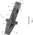
- FIG. 1 illustrates a material removal tool 10 with a unitary cemented carbide shank 12.
- the cemented carbide shank 12 extends from the mating end 14 of the material removal tool 10 toward the cutting end 16 of the material removal tool 10 and is formed of one piece.
- the cemented carbide shank 12 can have an internally arranged piece of steel, such as the steel rod 18 shown in FIG. 1 .
- a suitable mating surface 20 that mates with the base of the operating machine tool (not shown).
- a coupling 22 that at a first end 24 connects to the cemented carbide shank 12 and that at a second end 26 has a connector 28.
- a cap with mounted cutting inserts (not shown) is affixed to the connector 28.
- the typical prior art material removal tool exhibits catastrophic breakage of the cemented carbide shank, Without being held to one theory of failure, it is believed that bending, e.g., deflection of the distal end, of the tools with unitary shanks places a compressive load on one side of the shank and a tensile load on the other side of the shank.
- cemented carbide is generally fine grained (approximately 1 ⁇ m to 2 ⁇ m ) and the crack mean free path is low, characteristics which generally facilitate crack propagation and failure. Thus, when under tensile forces the unitary cemented carbide shank fails easily.
- machining with long reach material removal tools where push back is observed is machining of large, single-piece, forged structural components formed from high strength materials, predominantly high strength materials like titanium. These structural components are used in the aerospace industry, such as for commercial aircraft, and are very expensive. For example, these structural components can be >$200,000 before any machining is performed, and generally, many hours are required to complete the machining to finished specifications. There is a large savings potential (machine time & tool expense) by minimizing tool deflections and the need for "spring back" passes.
- Exemplary embodiments of a material removal tool uses a series of spacers stacked along the extension of the tool.
- the spacers are formed of a material that has a Young's modulus (E) that is greater than steel, i.e., greater than 30 x 10 6 pounds force per square inch (lbf/in 2 )
- E Young's modulus
- the same spacers can be used on various size, e.g., length and/or diameter, of tools with varying lengths of tools using more or less spacers in quantity. Standardizing the spacers combined with manufacturing in larger quantities allows for good economies. From a technical point, spacers place the stiffer material of the spacer at a location of greatest resistance to bending moments (i,e. highest sectional modulus).
- preloading first with a preload nut, and optionally & additionally with a cap, one can take further advantage of the compressive strength of the spacer material. Also, there are "built-in" relief points on the tensile half of the tool under bending moments when the spacers separate, slide or otherwise move relative to each other. In one exemplary embodiment, it is possible to preload the system sufficiently that no tensile resultant loads would be experienced when the tool is used. Finally, common parts, such as a spacer and a preload nut, minimizes parts (manufacturing cost low).
- the invention provides a material removal tool according to claim 1.
- An exemplary embodiment of the material removal tool comprises a housing at a mating end, an extension longitudinally extending from the housing to a distal end, a plurality of spacers arranged along the extension, and a nut at the distal end of the extension, wherein the plurality of spacers are formed from a material having a Young's modulus of greater than about 1,5 times that of steel.
- the invention also provides a method of manufacturing a material removal tool according to claim 15.
- An exemplary embodiment of the method of manufacturing a material removal tool comprises arranging a plurality of spacers along at least a portion of an extension, the extension longitudinally extending from a housing of the material removal tool to a distal end, fastening a nut at a distal end of the extension, and preloading the plurality of spacers into compression, wherein the plurality of spacers are formed from a material having a Young's modulus of greater than about 1.5 times that of steel.
- the invention also provides a method of machining a workpiece with the material removal tool according to claim 18.
- An exemplary embodiment of the method of machining a workpiece comprises removing material from the workpiece with a material removal tool, wherein the material removal tool includes a housing at a mating end, an extension longitudinally extending from the housing to a distal end, a plurality of spacers arranged along the extension, and a nut at the distal end of the extension, and wherein the plurality of spacers are formed from a material having a Young's modulus of greater than about 1.5 times that of steel.
- the workpiece may be formed from a titanium-based alloy.
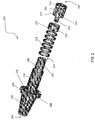
- FIG. 2 shows a partially disassembled, schematic view of an exemplary embodiment of a material removal tool with spacers
- the material removal tool 200 has a housing 202 at a mating end 204 and has a material removal end 206.
- An extension 208 longitudinally extends from the housing 202 to a distal end 210.
- a nut 212 is at the distal end 210 of the extension 208 and a cap 214 is mounted to the distal end 212 of the extension 208.
- the cap 214 includes a plurality of cutting inserts 216.
- the spacers 218 are formed from a material having a Young's modulus of about 1.5x, alternatively about twice, that of steel, i.e., about 40 x 10 6 lbf/in 2 , about 45 x 10 6 lbf/in 2 , about 50 x 10 6 lbf/in 2 , about 60 x 10 6 lbf/in 2 or more.
- the spacers 218 are formed from cemented carbide.
- the spacers 218 can take any physical form that, when positioned on the material removal tool, places the stiffer material of the spacer at a location of greatest resistance to bending moments (i.e. highest section modulus) of the material removal tool.
- One exemplary embodiment of the physical form is the shape of a washer.
- the spacer is a washer having an outer diameter surface and an inner diameter surface and the radius of the outer diameter surface ranges from about 1.33 to about 2 times the radius of the inner diameter surface.
- the number of spacers along the extension varies based on the length of the material removal tool.
- the material removal tool 300 has projection length L, which is from the gage line 302 to the cutting end 304, and has a diameter D.
- the gage line is the maximum diameter of the mating end that contacts the machine tool when in operation.
- a ratio of the projection length to the diameter is about 2:1 to about 18:1.
- Standard lengths are about 2:1, about 3:1, about 4:1, about 5:1, about 6:1, about 7:1, about 8:1 and about 12:1.
- any projection length and diameter can be used in that performance is improved using the disclosed spacers.
- the number of the spacers arranged along the extension varies.
- the nut 212 When attached to the extension 208, the nut 212 places an optional compressive preload on the plurality of spacers 218.
- An example of a suitable compressive preload is about 75% of a proof load of the threaded connection.
- Another example of a suitable compressive preload for a steel thread is achieved by attaching the nut 212 to the extension 208 with the thread of M39-4, 7H with a torque of about 200 to about 250 ft-lbs, alternatively about 225 ft-lbs.
- the compressive preload contributes to mitigating any tension loads that occur during operation of the material removal tool. As the spacers 218 are placed into compressive preload, the extension 208 is placed into tensile preload.
- the cap 214 mounted to the distal end 210 of the extension 208 includes a plurality of cutting inserts 216.
- Each cutting insert 216 is mounted to a seating surface in a pocket formed in the cap 214.
- Suitable cutting inserts can be of any type, e.g., milling, turning, boring.
- One exemplary embodiment of suitable cutting inserts is the side locking insert disclosed in U.S. Application No. 11/409,089 , entitled "Side Locking Insert and Material Removal Tool with Same,” filed April 24, 2006.
- the nut 212 is positioned around the circumference of the extension 208 at the distal end 210 and the cap 214 is mounted to a cross-section of the distal end 210 of the extension 208.
- a threaded portion 224 of the cap 214 can be threaded into threads made in the cross-section of the distal end 210 of the extension 208.
- the cap 214 When attached to the extension 208, the cap 214 can optionally provide a compressive preload on the plurality of spacers 218.
- An example of a suitable compressive preload resulting from the cap threaded into the extension is achieved by attaching the cap 214 to the extension 208 with a thread size of M20-2.5, 7H to a torque of about 150 to about 250 ft-lbs, alternatively about 200 ft-lbs.
- the cap 214 provides a compressive preload on the plurality of spacers 218, the cap 214 also provides a tensile preload to the extension 208.
- the housing 202 at the mating end 204 of the material removal tool 200 attaches to a machine tool, such as a HAAS VF6 milling machine, during operation.
- the housing can take any suitable form that allows attachment to a desired machine tool.
- the housing has a tapered surface, for example, tapered rearward or toward the mating end 204.
- a transition piece 226 can optionally be included at one end of the housing 202.
- An example of a transition piece 226 includes at least one feature for mating to an operating machine or to a storage system.
- the transition piece 226 can include a circumferential groove 228.
- the circumferential groove 228, or similar structure can provide an attachment point for mating the material removal tool 200 to a carousel storage system used in machining operations to store multiple material removal tools.
- the transition piece 226 can include a key slot 230.
- the key slot 230, or similar structure can provide an orientation or a mating with a corresponding feature on the machine tool when the material removal tool is mounted for use.
- the presently disclosed cap allows for component replacement of the cap without discarding the whole assembly of the material removal tool.
- a similar advantage is achieved by having the nut, spacers, and, if applicable, the extension and the housing, being separately replaceable.
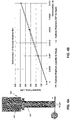
- FIG. 4B is a graph of the applied force as a function of deformation in two directions for the material removal tool shown in FIG. 4A .
- the material removal tool was measured from two directions: the first parallel to the key slot (see FIGS. 2 and 3 ) and the second 90° to the key slot.
- the resulting performance of the material removal tool is substantially the same, i.e., with the instrument error, for both the parallel and the 90° directions.
- FIGS. 5A and 5B relate to deformation observed when using a material removal tool formed of solid steel.
- FIG. 5A shows a schematic representation of a material removal tool 500 with a solid steel shank.
- FIG. 5B is a graph of the applied force as a function of deformation in two directions for the material removal tool shown in FIG. 5A .
- the material removal tool 500 was tested under the same conditions as those for material removal tool 400 in FIG. 4A , and the same testing regime was used.
- the resulting performance of the material removal tool are substantially the same, i.e., with the instrument error, for both the parallel and the 90° directions.
- the material removal tool with spacers ( FIG. 4A ) requires more force to achieve the same amount of deflection - 500 lbs for a 0.003 inch deformation for the material removal tool with spacers whereas only 300 lbs of force is needed for the same deflection in the material removal tool with a solid steel shank ( FIG. 5A ).
- the material removal tool with spacers is approximately about one-and-a-half times to about twice as stiff as the material removal tool with solid steel.
- the material removal tool with spacers will be more stiff than the material removal tool with solid steel by approximately the difference in the Young's modulus between the material of the spacers and that of steel. If different materials are used for different spacers on the same material removal tool, then prediction/comparison of the stiffness of the material removal tool as compared to a steel material removal tool can be made using Euler-Bernoulli equations for bending beams and considering the length varying value for the Young's modulus arising from the value of the Young's modulus of the individual spacers and the distance relationship from the gage line.
- FIG. 6 is a graph of applied bending torque as a function of angular deformation in two directions for a material removal tool with a solid steel shank (legend “solid steel” and curves labeled 600) and for an exemplary embodiment of a material removal tool with cemented carbide spacers (legend “carbide washers” and curves labeled 602).
- the measurements were taken parallel to and 90° to the key slot as described for FIGS. 4B and 5B .
- the material removal tool with cemented carbide spacers exhibited lower deformation at higher applied bending torque, indicative of a stiffer tool.
- the material removal tool with cemented carbide spacers required approximately one-and-a-half times the applied bending torque and is consistent with the difference in material properties between the solid steel shank and the cemented carbide washer stiffened tool.
- Static rigidity was defined as the amount of bending moment (measured in in*lbs) necessary to create 1 minute of the adapter angular deformation.
- Table 1 Static Rigidity material removal tool with solid steel material removal tool with cemented carbide spacers Factor 3213 in*lbs/min 5528 in*lbs/min 1.7
- FIG. 7 illustrates an exemplary embodiment of a material removal tool with spacers 700 operating to remove material from a workpiece 702.
- material is removed to a depth-of-cut (DOC) and a width-of-cut (WOC).
- Depth-of-cut was determined to be the maximum depth of material at that width that could be removed by a single pass of the material removal tool without observing "chatter" - the vibrations leading to deflection of the tool and typically producing a frequency correlated to the cutting insert(s) jumping off the workpiece and then returning to contact and continued machining.
- Comparison milling cuts were conducted using a vertical milling machine HAAS VF6 (30 HP). Milling parameters were: Width-of-cut: 1.0 inches Speed-of-cut: 400 sfm Feed rate: 0.10 inches per tooth (ipt)
- Table 2 Milling Cut Comparison Test Parameter material removal tool with solid steel material removal tool with cemented carbide spacers max. DOC 0.040 inches 0.080 inches
- the material removal tool with cemented carbide spacers demonstrated a two times larger depth of cut in a vibration free environment or substantially vibration free environment.
- the Milling Cut Comparison Test indicates that the material removal tool with the preloaded spacers provide a higher performance capacity for material removal tools with ratios (length to diameter) of 4:1 to 8:1 and suggests that material removal tools with higher ratios will demonstrate consistent results, e.g., substantially improved performance.
Landscapes
- Engineering & Computer Science (AREA)
- Mechanical Engineering (AREA)
- Cutting Tools, Boring Holders, And Turrets (AREA)
- Jigs For Machine Tools (AREA)
- Milling Processes (AREA)
Applications Claiming Priority (3)
| Application Number | Priority Date | Filing Date | Title |
|---|---|---|---|
| US90681407P | 2007-03-14 | 2007-03-14 | |
| US11/730,690 US7815403B2 (en) | 2007-03-14 | 2007-04-03 | Material removal tool stiffened with spacers arranged along a length |
| PCT/US2008/003157 WO2008112197A1 (en) | 2007-03-14 | 2008-03-11 | Material removal tool stiffened with spacers arranged along a length |
Publications (3)
| Publication Number | Publication Date |
|---|---|
| EP2125303A1 EP2125303A1 (en) | 2009-12-02 |
| EP2125303A4 EP2125303A4 (en) | 2013-03-27 |
| EP2125303B1 true EP2125303B1 (en) | 2017-06-28 |
Family
ID=39759831
Family Applications (1)
| Application Number | Title | Priority Date | Filing Date |
|---|---|---|---|
| EP08726654.0A Not-in-force EP2125303B1 (en) | 2007-03-14 | 2008-03-11 | Material removal tool stiffened with spacers arranged along a length |
Country Status (9)
| Country | Link |
|---|---|
| US (1) | US7815403B2 (cg-RX-API-DMAC7.html) |
| EP (1) | EP2125303B1 (cg-RX-API-DMAC7.html) |
| JP (1) | JP5330275B2 (cg-RX-API-DMAC7.html) |
| KR (1) | KR20100015467A (cg-RX-API-DMAC7.html) |
| CN (1) | CN101668615B (cg-RX-API-DMAC7.html) |
| BR (1) | BRPI0808478A2 (cg-RX-API-DMAC7.html) |
| CA (1) | CA2679737A1 (cg-RX-API-DMAC7.html) |
| MX (1) | MX2009009803A (cg-RX-API-DMAC7.html) |
| WO (1) | WO2008112197A1 (cg-RX-API-DMAC7.html) |
Families Citing this family (11)
| Publication number | Priority date | Publication date | Assignee | Title |
|---|---|---|---|---|
| US8529173B2 (en) * | 2008-01-22 | 2013-09-10 | Valenite, Llc | Method to align characteristic frequency of material removal tool and rotation speed of spindle of machine tool and material removal tool so aligned |
| SE533786C2 (sv) * | 2009-05-25 | 2011-01-11 | Sandvik Intellectual Property | Anordning och förfarande för fräsning av material |
| US8821082B1 (en) * | 2009-09-29 | 2014-09-02 | The Boeing Company | Stiffening sleeve for tool holders |
| US8926238B1 (en) | 2009-09-29 | 2015-01-06 | The Boeing Company | Cutting tool sleeve for tool holders |
| SE535054C2 (sv) * | 2010-03-17 | 2012-03-27 | Sandvik Intellectual Property | Fräsverktyg för skärande bearbetning med dämpningsorgan anordnande i verktygskroppen |
| US8784016B2 (en) * | 2011-07-01 | 2014-07-22 | Kennametal Inc. | Rotary cutting tool with vibration damping device |
| CN104002206B (zh) * | 2013-02-21 | 2016-05-11 | 协竑企业有限公司 | 微细钻头的插置方法、插置及取置装置 |
| US9221141B1 (en) * | 2013-02-27 | 2015-12-29 | The Boeing Company | Tuned mass tool holder |
| JP6348284B2 (ja) * | 2014-01-08 | 2018-06-27 | 株式会社神戸製鋼所 | 切削加工における切削条件の設計方法 |
| JP6651494B2 (ja) | 2017-12-06 | 2020-02-19 | 三菱重工コンプレッサ株式会社 | 切削工具及び切削工具の組み立て方法 |
| CN113523433A (zh) * | 2021-08-11 | 2021-10-22 | 一汽解放汽车有限公司 | 一种铣铰刀 |
Family Cites Families (27)
| Publication number | Priority date | Publication date | Assignee | Title |
|---|---|---|---|---|
| US2431581A (en) * | 1944-09-27 | 1947-11-25 | Robert G Owen | Milling machine cutter |
| US2843921A (en) * | 1956-06-26 | 1958-07-22 | Mallory & Co Inc P R | High-strength high-density tungsten base alloys |
| US3207009A (en) * | 1964-04-08 | 1965-09-21 | Kennametal Inc | Vibration damping device |
| US4011026A (en) * | 1972-08-03 | 1977-03-08 | Genio Tools, Inc. | Interlock cutting tool holder |
| SE361276B (cg-RX-API-DMAC7.html) * | 1972-12-12 | 1973-10-29 | Sandvik Ab | |
| US3938626A (en) * | 1974-09-03 | 1976-02-17 | The Valeron Corporation | Vibration damping assembly |
| US4037282A (en) | 1976-03-08 | 1977-07-26 | Dahl Norman C | Process for creating overload protection against yielding in bolts |
| JPS55112717A (en) * | 1979-02-26 | 1980-08-30 | Toshiba Tungaloy Co Ltd | Spacer for rotary shearing device |
| CH659025A5 (de) * | 1983-03-17 | 1986-12-31 | Studer Ag Fritz Maschf | Schleifdorn zur aufnahme von schleifscheiben. |
| US4885964A (en) * | 1984-09-14 | 1989-12-12 | Industrial Tools, Inc. | Tape slitter adjustment means |
| SU1349887A1 (ru) * | 1985-05-22 | 1987-11-07 | Московский станкостроительный завод "Красный пролетарий" им.А.И.Ефремова | Наборный режущий инструмент |
| US5316061A (en) * | 1993-03-16 | 1994-05-31 | Lee Leonard G | Shims for dado cutter set |
| RU2109599C1 (ru) * | 1997-01-08 | 1998-04-27 | Владимир Васильевич Вождаенко | Держатель инструмента |
| US5996659A (en) * | 1998-01-09 | 1999-12-07 | Burgess; Michael | Matched pair of plywood edge-banding router bits |
| US6517427B1 (en) | 1998-02-23 | 2003-02-11 | Shin-Etsu Chemical Co., Ltd. | Abrasive-bladed multiple cutting wheel assembly |
| JP2000346038A (ja) * | 1999-06-01 | 2000-12-12 | Seibu Polymer Corp | 構造物用弾性ワッシャー |
| US6450738B1 (en) | 2001-02-08 | 2002-09-17 | Ingersoll Cutting Tool Company | Cutting fluid distributor for milling cutters |
| GB2377478B (en) * | 2001-07-13 | 2004-05-05 | Nsk Steering Sys Europ Ltd | Steering column clamping mechanism |
| FR2838361B1 (fr) * | 2002-04-11 | 2004-12-17 | Safety Fabrique De Carbure De | Dispositif de bridage d'une plaquette de coupe amovible et outil support d'un tel dispositif |
| WO2005068118A1 (de) * | 2004-01-16 | 2005-07-28 | Franz Haimer Maschinenbau Kg | Schwingungsdämpfter werkzeughalter |
| US20050214087A1 (en) * | 2004-03-26 | 2005-09-29 | Agapiou John S | Spacer adapter for toolholders |
| JP4349576B2 (ja) * | 2004-04-15 | 2009-10-21 | 株式会社日研工作所 | 工具ホルダ |
| JP2005329509A (ja) * | 2004-05-20 | 2005-12-02 | Tungaloy Corp | 切削工具 |
| JP4648072B2 (ja) * | 2005-04-28 | 2011-03-09 | 株式会社日立プラントテクノロジー | ダンパーを備えた工具及びそれを用いた流体機械の羽根車もしくは案内羽根の製造方法 |
| US7131473B1 (en) | 2005-07-19 | 2006-11-07 | Freud America, Inc. | Programmable coping bit |
| JP2007038310A (ja) * | 2005-07-29 | 2007-02-15 | Shin Caterpillar Mitsubishi Ltd | 切削工具 |
| US7607868B2 (en) | 2006-04-24 | 2009-10-27 | Valenite Llc | Side locking insert and material removal tool with same |
-
2007
- 2007-04-03 US US11/730,690 patent/US7815403B2/en not_active Expired - Fee Related
-
2008
- 2008-03-11 WO PCT/US2008/003157 patent/WO2008112197A1/en not_active Ceased
- 2008-03-11 BR BRPI0808478-5A patent/BRPI0808478A2/pt not_active IP Right Cessation
- 2008-03-11 JP JP2009553597A patent/JP5330275B2/ja not_active Expired - Fee Related
- 2008-03-11 KR KR1020097021121A patent/KR20100015467A/ko not_active Withdrawn
- 2008-03-11 MX MX2009009803A patent/MX2009009803A/es not_active Application Discontinuation
- 2008-03-11 EP EP08726654.0A patent/EP2125303B1/en not_active Not-in-force
- 2008-03-11 CA CA002679737A patent/CA2679737A1/en not_active Abandoned
- 2008-03-11 CN CN2008800081919A patent/CN101668615B/zh not_active Expired - Fee Related
Non-Patent Citations (1)
| Title |
|---|
| None * |
Also Published As
| Publication number | Publication date |
|---|---|
| US20080226401A1 (en) | 2008-09-18 |
| JP5330275B2 (ja) | 2013-10-30 |
| EP2125303A4 (en) | 2013-03-27 |
| KR20100015467A (ko) | 2010-02-12 |
| CN101668615B (zh) | 2013-01-02 |
| CA2679737A1 (en) | 2008-09-18 |
| BRPI0808478A2 (pt) | 2014-07-01 |
| JP2010521322A (ja) | 2010-06-24 |
| EP2125303A1 (en) | 2009-12-02 |
| US7815403B2 (en) | 2010-10-19 |
| CN101668615A (zh) | 2010-03-10 |
| WO2008112197A1 (en) | 2008-09-18 |
| MX2009009803A (es) | 2009-09-24 |
Similar Documents
| Publication | Publication Date | Title |
|---|---|---|
| US7815403B2 (en) | Material removal tool stiffened with spacers arranged along a length | |
| KR101437184B1 (ko) | 조정가능 탈착식 절삭 인서트를 구비한 절삭 공구 | |
| US8708611B2 (en) | T-slot cutter having separate centering and torque-transmitting portions | |
| US8974154B2 (en) | Cutting insert and shim for milling cutters | |
| US10046402B2 (en) | Rotary cutting tool | |
| WO2003066260A1 (en) | Tunable toolholder | |
| KR20000062944A (ko) | 공구 홀더 및 공구 홀더 장착 장치 | |
| CZ58099A3 (cs) | Spoj pro nástrojové části, nástroj, řezná hlava, držák, podložka a způsob vzájemného spojování | |
| KR20090033326A (ko) | 탈착식 인서트와 이를 구비한 소재제거공구 | |
| EP3542934B1 (en) | Reamer | |
| US3859699A (en) | Cutting tool | |
| CN106111253A (zh) | 截齿保持器 | |
| US9782841B2 (en) | Cutting tool | |
| EP2219809B1 (en) | Cutting tool | |
| US8388272B2 (en) | High speed milling cutter with tapered pin | |
| EP3363571B1 (en) | Rotary cutting blade material and method for manufacturing the same | |
| EP1810768B1 (en) | Rotary cutting tool with cutter blade play regulation mechanism | |
| CN107249797A (zh) | 机械加工工具 | |
| EP3263263B1 (en) | Hobbing tool with replaceable cutting inserts | |
| Toh | Tool life and tool wear during high-speed rough milling using alternative cutter path strategies | |
| US10814408B2 (en) | Replaceable-tip cutting tool main body and replaceable-tip cutting tool | |
| JP5893960B2 (ja) | 刃先交換式内径加工用切削工具 | |
| US12208486B1 (en) | Secure grinder blade and tapered tool—side locking hub for flush cutting concrete | |
| EP4313482B1 (en) | Damper device, machine tool and method of assembling said damper device | |
| US20250296159A1 (en) | Milling tool |
Legal Events
| Date | Code | Title | Description |
|---|---|---|---|
| PUAI | Public reference made under article 153(3) epc to a published international application that has entered the european phase |
Free format text: ORIGINAL CODE: 0009012 |
|
| 17P | Request for examination filed |
Effective date: 20090921 |
|
| AK | Designated contracting states |
Kind code of ref document: A1 Designated state(s): AT BE BG CH CY CZ DE DK EE ES FI FR GB GR HR HU IE IS IT LI LT LU LV MC MT NL NO PL PT RO SE SI SK TR |
|
| DAX | Request for extension of the european patent (deleted) | ||
| REG | Reference to a national code |
Ref country code: DE Ref legal event code: R079 Ref document number: 602008050863 Country of ref document: DE Free format text: PREVIOUS MAIN CLASS: B26D0001120000 Ipc: B23C0005000000 |
|
| A4 | Supplementary search report drawn up and despatched |
Effective date: 20130222 |
|
| RIC1 | Information provided on ipc code assigned before grant |
Ipc: B23C 5/10 20060101ALI20130218BHEP Ipc: B23C 5/00 20060101AFI20130218BHEP |
|
| GRAP | Despatch of communication of intention to grant a patent |
Free format text: ORIGINAL CODE: EPIDOSNIGR1 |
|
| INTG | Intention to grant announced |
Effective date: 20170222 |
|
| GRAS | Grant fee paid |
Free format text: ORIGINAL CODE: EPIDOSNIGR3 |
|
| GRAA | (expected) grant |
Free format text: ORIGINAL CODE: 0009210 |
|
| AK | Designated contracting states |
Kind code of ref document: B1 Designated state(s): AT BE BG CH CY CZ DE DK EE ES FI FR GB GR HR HU IE IS IT LI LT LU LV MC MT NL NO PL PT RO SE SI SK TR |
|
| REG | Reference to a national code |
Ref country code: GB Ref legal event code: FG4D |
|
| REG | Reference to a national code |
Ref country code: CH Ref legal event code: EP |
|
| REG | Reference to a national code |
Ref country code: AT Ref legal event code: REF Ref document number: 904413 Country of ref document: AT Kind code of ref document: T Effective date: 20170715 |
|
| REG | Reference to a national code |
Ref country code: IE Ref legal event code: FG4D |
|
| REG | Reference to a national code |
Ref country code: DE Ref legal event code: R096 Ref document number: 602008050863 Country of ref document: DE |
|
| PG25 | Lapsed in a contracting state [announced via postgrant information from national office to epo] |
Ref country code: GR Free format text: LAPSE BECAUSE OF FAILURE TO SUBMIT A TRANSLATION OF THE DESCRIPTION OR TO PAY THE FEE WITHIN THE PRESCRIBED TIME-LIMIT Effective date: 20170929 Ref country code: FI Free format text: LAPSE BECAUSE OF FAILURE TO SUBMIT A TRANSLATION OF THE DESCRIPTION OR TO PAY THE FEE WITHIN THE PRESCRIBED TIME-LIMIT Effective date: 20170628 Ref country code: LT Free format text: LAPSE BECAUSE OF FAILURE TO SUBMIT A TRANSLATION OF THE DESCRIPTION OR TO PAY THE FEE WITHIN THE PRESCRIBED TIME-LIMIT Effective date: 20170628 Ref country code: HR Free format text: LAPSE BECAUSE OF FAILURE TO SUBMIT A TRANSLATION OF THE DESCRIPTION OR TO PAY THE FEE WITHIN THE PRESCRIBED TIME-LIMIT Effective date: 20170628 Ref country code: NO Free format text: LAPSE BECAUSE OF FAILURE TO SUBMIT A TRANSLATION OF THE DESCRIPTION OR TO PAY THE FEE WITHIN THE PRESCRIBED TIME-LIMIT Effective date: 20170928 |
|
| REG | Reference to a national code |
Ref country code: NL Ref legal event code: MP Effective date: 20170628 |
|
| REG | Reference to a national code |
Ref country code: LT Ref legal event code: MG4D |
|
| REG | Reference to a national code |
Ref country code: AT Ref legal event code: MK05 Ref document number: 904413 Country of ref document: AT Kind code of ref document: T Effective date: 20170628 |
|
| PG25 | Lapsed in a contracting state [announced via postgrant information from national office to epo] |
Ref country code: SE Free format text: LAPSE BECAUSE OF FAILURE TO SUBMIT A TRANSLATION OF THE DESCRIPTION OR TO PAY THE FEE WITHIN THE PRESCRIBED TIME-LIMIT Effective date: 20170628 Ref country code: LV Free format text: LAPSE BECAUSE OF FAILURE TO SUBMIT A TRANSLATION OF THE DESCRIPTION OR TO PAY THE FEE WITHIN THE PRESCRIBED TIME-LIMIT Effective date: 20170628 Ref country code: NL Free format text: LAPSE BECAUSE OF FAILURE TO SUBMIT A TRANSLATION OF THE DESCRIPTION OR TO PAY THE FEE WITHIN THE PRESCRIBED TIME-LIMIT Effective date: 20170628 Ref country code: BG Free format text: LAPSE BECAUSE OF FAILURE TO SUBMIT A TRANSLATION OF THE DESCRIPTION OR TO PAY THE FEE WITHIN THE PRESCRIBED TIME-LIMIT Effective date: 20170928 |
|
| PG25 | Lapsed in a contracting state [announced via postgrant information from national office to epo] |
Ref country code: EE Free format text: LAPSE BECAUSE OF FAILURE TO SUBMIT A TRANSLATION OF THE DESCRIPTION OR TO PAY THE FEE WITHIN THE PRESCRIBED TIME-LIMIT Effective date: 20170628 Ref country code: RO Free format text: LAPSE BECAUSE OF FAILURE TO SUBMIT A TRANSLATION OF THE DESCRIPTION OR TO PAY THE FEE WITHIN THE PRESCRIBED TIME-LIMIT Effective date: 20170628 Ref country code: CZ Free format text: LAPSE BECAUSE OF FAILURE TO SUBMIT A TRANSLATION OF THE DESCRIPTION OR TO PAY THE FEE WITHIN THE PRESCRIBED TIME-LIMIT Effective date: 20170628 Ref country code: AT Free format text: LAPSE BECAUSE OF FAILURE TO SUBMIT A TRANSLATION OF THE DESCRIPTION OR TO PAY THE FEE WITHIN THE PRESCRIBED TIME-LIMIT Effective date: 20170628 Ref country code: SK Free format text: LAPSE BECAUSE OF FAILURE TO SUBMIT A TRANSLATION OF THE DESCRIPTION OR TO PAY THE FEE WITHIN THE PRESCRIBED TIME-LIMIT Effective date: 20170628 |
|
| PG25 | Lapsed in a contracting state [announced via postgrant information from national office to epo] |
Ref country code: ES Free format text: LAPSE BECAUSE OF FAILURE TO SUBMIT A TRANSLATION OF THE DESCRIPTION OR TO PAY THE FEE WITHIN THE PRESCRIBED TIME-LIMIT Effective date: 20170628 Ref country code: IT Free format text: LAPSE BECAUSE OF FAILURE TO SUBMIT A TRANSLATION OF THE DESCRIPTION OR TO PAY THE FEE WITHIN THE PRESCRIBED TIME-LIMIT Effective date: 20170628 Ref country code: PL Free format text: LAPSE BECAUSE OF FAILURE TO SUBMIT A TRANSLATION OF THE DESCRIPTION OR TO PAY THE FEE WITHIN THE PRESCRIBED TIME-LIMIT Effective date: 20170628 Ref country code: IS Free format text: LAPSE BECAUSE OF FAILURE TO SUBMIT A TRANSLATION OF THE DESCRIPTION OR TO PAY THE FEE WITHIN THE PRESCRIBED TIME-LIMIT Effective date: 20171028 |
|
| REG | Reference to a national code |
Ref country code: DE Ref legal event code: R097 Ref document number: 602008050863 Country of ref document: DE |
|
| PG25 | Lapsed in a contracting state [announced via postgrant information from national office to epo] |
Ref country code: DK Free format text: LAPSE BECAUSE OF FAILURE TO SUBMIT A TRANSLATION OF THE DESCRIPTION OR TO PAY THE FEE WITHIN THE PRESCRIBED TIME-LIMIT Effective date: 20170628 |
|
| PLBE | No opposition filed within time limit |
Free format text: ORIGINAL CODE: 0009261 |
|
| STAA | Information on the status of an ep patent application or granted ep patent |
Free format text: STATUS: NO OPPOSITION FILED WITHIN TIME LIMIT |
|
| 26N | No opposition filed |
Effective date: 20180329 |
|
| PG25 | Lapsed in a contracting state [announced via postgrant information from national office to epo] |
Ref country code: SI Free format text: LAPSE BECAUSE OF FAILURE TO SUBMIT A TRANSLATION OF THE DESCRIPTION OR TO PAY THE FEE WITHIN THE PRESCRIBED TIME-LIMIT Effective date: 20170628 |
|
| REG | Reference to a national code |
Ref country code: CH Ref legal event code: PL |
|
| GBPC | Gb: european patent ceased through non-payment of renewal fee |
Effective date: 20180311 |
|
| PG25 | Lapsed in a contracting state [announced via postgrant information from national office to epo] |
Ref country code: MC Free format text: LAPSE BECAUSE OF FAILURE TO SUBMIT A TRANSLATION OF THE DESCRIPTION OR TO PAY THE FEE WITHIN THE PRESCRIBED TIME-LIMIT Effective date: 20170628 |
|
| REG | Reference to a national code |
Ref country code: BE Ref legal event code: MM Effective date: 20180331 |
|
| REG | Reference to a national code |
Ref country code: IE Ref legal event code: MM4A |
|
| PG25 | Lapsed in a contracting state [announced via postgrant information from national office to epo] |
Ref country code: LU Free format text: LAPSE BECAUSE OF NON-PAYMENT OF DUE FEES Effective date: 20180311 |
|
| PG25 | Lapsed in a contracting state [announced via postgrant information from national office to epo] |
Ref country code: IE Free format text: LAPSE BECAUSE OF NON-PAYMENT OF DUE FEES Effective date: 20180311 |
|
| PG25 | Lapsed in a contracting state [announced via postgrant information from national office to epo] |
Ref country code: CH Free format text: LAPSE BECAUSE OF NON-PAYMENT OF DUE FEES Effective date: 20180331 Ref country code: LI Free format text: LAPSE BECAUSE OF NON-PAYMENT OF DUE FEES Effective date: 20180331 Ref country code: BE Free format text: LAPSE BECAUSE OF NON-PAYMENT OF DUE FEES Effective date: 20180331 Ref country code: GB Free format text: LAPSE BECAUSE OF NON-PAYMENT OF DUE FEES Effective date: 20180311 |
|
| PG25 | Lapsed in a contracting state [announced via postgrant information from national office to epo] |
Ref country code: FR Free format text: LAPSE BECAUSE OF NON-PAYMENT OF DUE FEES Effective date: 20180331 |
|
| PGFP | Annual fee paid to national office [announced via postgrant information from national office to epo] |
Ref country code: DE Payment date: 20190226 Year of fee payment: 12 |
|
| PG25 | Lapsed in a contracting state [announced via postgrant information from national office to epo] |
Ref country code: MT Free format text: LAPSE BECAUSE OF NON-PAYMENT OF DUE FEES Effective date: 20180311 |
|
| PG25 | Lapsed in a contracting state [announced via postgrant information from national office to epo] |
Ref country code: TR Free format text: LAPSE BECAUSE OF FAILURE TO SUBMIT A TRANSLATION OF THE DESCRIPTION OR TO PAY THE FEE WITHIN THE PRESCRIBED TIME-LIMIT Effective date: 20170628 |
|
| PG25 | Lapsed in a contracting state [announced via postgrant information from national office to epo] |
Ref country code: PT Free format text: LAPSE BECAUSE OF FAILURE TO SUBMIT A TRANSLATION OF THE DESCRIPTION OR TO PAY THE FEE WITHIN THE PRESCRIBED TIME-LIMIT Effective date: 20170628 Ref country code: HU Free format text: LAPSE BECAUSE OF FAILURE TO SUBMIT A TRANSLATION OF THE DESCRIPTION OR TO PAY THE FEE WITHIN THE PRESCRIBED TIME-LIMIT; INVALID AB INITIO Effective date: 20080311 |
|
| PG25 | Lapsed in a contracting state [announced via postgrant information from national office to epo] |
Ref country code: CY Free format text: LAPSE BECAUSE OF FAILURE TO SUBMIT A TRANSLATION OF THE DESCRIPTION OR TO PAY THE FEE WITHIN THE PRESCRIBED TIME-LIMIT Effective date: 20170628 |
|
| REG | Reference to a national code |
Ref country code: DE Ref legal event code: R119 Ref document number: 602008050863 Country of ref document: DE |
|
| PG25 | Lapsed in a contracting state [announced via postgrant information from national office to epo] |
Ref country code: DE Free format text: LAPSE BECAUSE OF NON-PAYMENT OF DUE FEES Effective date: 20201001 |