EP2124833B1 - Dispositif d'osteosynthese - Google Patents
Dispositif d'osteosynthese Download PDFInfo
- Publication number
- EP2124833B1 EP2124833B1 EP08799857A EP08799857A EP2124833B1 EP 2124833 B1 EP2124833 B1 EP 2124833B1 EP 08799857 A EP08799857 A EP 08799857A EP 08799857 A EP08799857 A EP 08799857A EP 2124833 B1 EP2124833 B1 EP 2124833B1
- Authority
- EP
- European Patent Office
- Prior art keywords
- legs
- width
- closed
- l2ab
- length
- Prior art date
- Legal status (The legal status is an assumption and is not a legal conclusion. Google has not performed a legal analysis and makes no representation as to the accuracy of the status listed.)
- Active
Links
Images


Classifications
-
- A—HUMAN NECESSITIES
- A61—MEDICAL OR VETERINARY SCIENCE; HYGIENE
- A61B—DIAGNOSIS; SURGERY; IDENTIFICATION
- A61B17/00—Surgical instruments, devices or methods
- A61B17/56—Surgical instruments or methods for treatment of bones or joints; Devices specially adapted therefor
- A61B17/58—Surgical instruments or methods for treatment of bones or joints; Devices specially adapted therefor for osteosynthesis, e.g. bone plates, screws or setting implements
- A61B17/68—Internal fixation devices, including fasteners and spinal fixators, even if a part thereof projects from the skin
- A61B17/72—Intramedullary devices, e.g. pins or nails
-
- A—HUMAN NECESSITIES
- A61—MEDICAL OR VETERINARY SCIENCE; HYGIENE
- A61B—DIAGNOSIS; SURGERY; IDENTIFICATION
- A61B17/00—Surgical instruments, devices or methods
- A61B17/56—Surgical instruments or methods for treatment of bones or joints; Devices specially adapted therefor
- A61B17/58—Surgical instruments or methods for treatment of bones or joints; Devices specially adapted therefor for osteosynthesis, e.g. bone plates, screws or setting implements
- A61B17/68—Internal fixation devices, including fasteners and spinal fixators, even if a part thereof projects from the skin
- A61B17/72—Intramedullary devices, e.g. pins or nails
- A61B17/7233—Intramedullary devices, e.g. pins or nails with special means of locking the nail to the bone
- A61B17/7258—Intramedullary devices, e.g. pins or nails with special means of locking the nail to the bone with laterally expanding parts, e.g. for gripping the bone
- A61B17/7266—Intramedullary devices, e.g. pins or nails with special means of locking the nail to the bone with laterally expanding parts, e.g. for gripping the bone with fingers moving radially outwardly
-
- A—HUMAN NECESSITIES
- A61—MEDICAL OR VETERINARY SCIENCE; HYGIENE
- A61B—DIAGNOSIS; SURGERY; IDENTIFICATION
- A61B17/00—Surgical instruments, devices or methods
- A61B17/56—Surgical instruments or methods for treatment of bones or joints; Devices specially adapted therefor
- A61B17/58—Surgical instruments or methods for treatment of bones or joints; Devices specially adapted therefor for osteosynthesis, e.g. bone plates, screws or setting implements
- A61B17/68—Internal fixation devices, including fasteners and spinal fixators, even if a part thereof projects from the skin
- A61B17/72—Intramedullary devices, e.g. pins or nails
- A61B17/7283—Intramedullary devices, e.g. pins or nails with special cross-section of the nail
-
- A—HUMAN NECESSITIES
- A61—MEDICAL OR VETERINARY SCIENCE; HYGIENE
- A61B—DIAGNOSIS; SURGERY; IDENTIFICATION
- A61B17/00—Surgical instruments, devices or methods
- A61B17/56—Surgical instruments or methods for treatment of bones or joints; Devices specially adapted therefor
- A61B17/58—Surgical instruments or methods for treatment of bones or joints; Devices specially adapted therefor for osteosynthesis, e.g. bone plates, screws or setting implements
- A61B17/68—Internal fixation devices, including fasteners and spinal fixators, even if a part thereof projects from the skin
- A61B17/72—Intramedullary devices, e.g. pins or nails
- A61B17/7291—Intramedullary devices, e.g. pins or nails for small bones, e.g. in the foot, ankle, hand or wrist
-
- A—HUMAN NECESSITIES
- A61—MEDICAL OR VETERINARY SCIENCE; HYGIENE
- A61F—FILTERS IMPLANTABLE INTO BLOOD VESSELS; PROSTHESES; DEVICES PROVIDING PATENCY TO, OR PREVENTING COLLAPSING OF, TUBULAR STRUCTURES OF THE BODY, e.g. STENTS; ORTHOPAEDIC, NURSING OR CONTRACEPTIVE DEVICES; FOMENTATION; TREATMENT OR PROTECTION OF EYES OR EARS; BANDAGES, DRESSINGS OR ABSORBENT PADS; FIRST-AID KITS
- A61F2/00—Filters implantable into blood vessels; Prostheses, i.e. artificial substitutes or replacements for parts of the body; Appliances for connecting them with the body; Devices providing patency to, or preventing collapsing of, tubular structures of the body, e.g. stents
- A61F2/02—Prostheses implantable into the body
- A61F2/30—Joints
-
- A—HUMAN NECESSITIES
- A61—MEDICAL OR VETERINARY SCIENCE; HYGIENE
- A61F—FILTERS IMPLANTABLE INTO BLOOD VESSELS; PROSTHESES; DEVICES PROVIDING PATENCY TO, OR PREVENTING COLLAPSING OF, TUBULAR STRUCTURES OF THE BODY, e.g. STENTS; ORTHOPAEDIC, NURSING OR CONTRACEPTIVE DEVICES; FOMENTATION; TREATMENT OR PROTECTION OF EYES OR EARS; BANDAGES, DRESSINGS OR ABSORBENT PADS; FIRST-AID KITS
- A61F2/00—Filters implantable into blood vessels; Prostheses, i.e. artificial substitutes or replacements for parts of the body; Appliances for connecting them with the body; Devices providing patency to, or preventing collapsing of, tubular structures of the body, e.g. stents
- A61F2/02—Prostheses implantable into the body
- A61F2/30—Joints
- A61F2/42—Joints for wrists or ankles; for hands, e.g. fingers; for feet, e.g. toes
- A61F2/4241—Joints for wrists or ankles; for hands, e.g. fingers; for feet, e.g. toes for hands, e.g. fingers
-
- A—HUMAN NECESSITIES
- A61—MEDICAL OR VETERINARY SCIENCE; HYGIENE
- A61B—DIAGNOSIS; SURGERY; IDENTIFICATION
- A61B17/00—Surgical instruments, devices or methods
- A61B17/56—Surgical instruments or methods for treatment of bones or joints; Devices specially adapted therefor
- A61B17/58—Surgical instruments or methods for treatment of bones or joints; Devices specially adapted therefor for osteosynthesis, e.g. bone plates, screws or setting implements
- A61B17/68—Internal fixation devices, including fasteners and spinal fixators, even if a part thereof projects from the skin
- A61B17/72—Intramedullary devices, e.g. pins or nails
- A61B17/7216—Intramedullary devices, e.g. pins or nails for bone lengthening or compression
- A61B17/7225—Intramedullary devices, e.g. pins or nails for bone lengthening or compression for bone compression
-
- A—HUMAN NECESSITIES
- A61—MEDICAL OR VETERINARY SCIENCE; HYGIENE
- A61F—FILTERS IMPLANTABLE INTO BLOOD VESSELS; PROSTHESES; DEVICES PROVIDING PATENCY TO, OR PREVENTING COLLAPSING OF, TUBULAR STRUCTURES OF THE BODY, e.g. STENTS; ORTHOPAEDIC, NURSING OR CONTRACEPTIVE DEVICES; FOMENTATION; TREATMENT OR PROTECTION OF EYES OR EARS; BANDAGES, DRESSINGS OR ABSORBENT PADS; FIRST-AID KITS
- A61F2/00—Filters implantable into blood vessels; Prostheses, i.e. artificial substitutes or replacements for parts of the body; Appliances for connecting them with the body; Devices providing patency to, or preventing collapsing of, tubular structures of the body, e.g. stents
- A61F2/02—Prostheses implantable into the body
- A61F2/30—Joints
- A61F2002/30001—Additional features of subject-matter classified in A61F2/28, A61F2/30 and subgroups thereof
- A61F2002/30003—Material related properties of the prosthesis or of a coating on the prosthesis
- A61F2002/3006—Properties of materials and coating materials
- A61F2002/30092—Properties of materials and coating materials using shape memory or superelastic materials, e.g. nitinol
-
- A—HUMAN NECESSITIES
- A61—MEDICAL OR VETERINARY SCIENCE; HYGIENE
- A61F—FILTERS IMPLANTABLE INTO BLOOD VESSELS; PROSTHESES; DEVICES PROVIDING PATENCY TO, OR PREVENTING COLLAPSING OF, TUBULAR STRUCTURES OF THE BODY, e.g. STENTS; ORTHOPAEDIC, NURSING OR CONTRACEPTIVE DEVICES; FOMENTATION; TREATMENT OR PROTECTION OF EYES OR EARS; BANDAGES, DRESSINGS OR ABSORBENT PADS; FIRST-AID KITS
- A61F2/00—Filters implantable into blood vessels; Prostheses, i.e. artificial substitutes or replacements for parts of the body; Appliances for connecting them with the body; Devices providing patency to, or preventing collapsing of, tubular structures of the body, e.g. stents
- A61F2/02—Prostheses implantable into the body
- A61F2/30—Joints
- A61F2002/30001—Additional features of subject-matter classified in A61F2/28, A61F2/30 and subgroups thereof
- A61F2002/30108—Shapes
- A61F2002/3011—Cross-sections or two-dimensional shapes
- A61F2002/30159—Concave polygonal shapes
- A61F2002/30166—H-shaped or I-shaped
-
- A—HUMAN NECESSITIES
- A61—MEDICAL OR VETERINARY SCIENCE; HYGIENE
- A61F—FILTERS IMPLANTABLE INTO BLOOD VESSELS; PROSTHESES; DEVICES PROVIDING PATENCY TO, OR PREVENTING COLLAPSING OF, TUBULAR STRUCTURES OF THE BODY, e.g. STENTS; ORTHOPAEDIC, NURSING OR CONTRACEPTIVE DEVICES; FOMENTATION; TREATMENT OR PROTECTION OF EYES OR EARS; BANDAGES, DRESSINGS OR ABSORBENT PADS; FIRST-AID KITS
- A61F2/00—Filters implantable into blood vessels; Prostheses, i.e. artificial substitutes or replacements for parts of the body; Appliances for connecting them with the body; Devices providing patency to, or preventing collapsing of, tubular structures of the body, e.g. stents
- A61F2/02—Prostheses implantable into the body
- A61F2/30—Joints
- A61F2002/30001—Additional features of subject-matter classified in A61F2/28, A61F2/30 and subgroups thereof
- A61F2002/30108—Shapes
- A61F2002/3011—Cross-sections or two-dimensional shapes
- A61F2002/30159—Concave polygonal shapes
- A61F2002/30179—X-shaped
-
- A—HUMAN NECESSITIES
- A61—MEDICAL OR VETERINARY SCIENCE; HYGIENE
- A61F—FILTERS IMPLANTABLE INTO BLOOD VESSELS; PROSTHESES; DEVICES PROVIDING PATENCY TO, OR PREVENTING COLLAPSING OF, TUBULAR STRUCTURES OF THE BODY, e.g. STENTS; ORTHOPAEDIC, NURSING OR CONTRACEPTIVE DEVICES; FOMENTATION; TREATMENT OR PROTECTION OF EYES OR EARS; BANDAGES, DRESSINGS OR ABSORBENT PADS; FIRST-AID KITS
- A61F2/00—Filters implantable into blood vessels; Prostheses, i.e. artificial substitutes or replacements for parts of the body; Appliances for connecting them with the body; Devices providing patency to, or preventing collapsing of, tubular structures of the body, e.g. stents
- A61F2/02—Prostheses implantable into the body
- A61F2/30—Joints
- A61F2002/30001—Additional features of subject-matter classified in A61F2/28, A61F2/30 and subgroups thereof
- A61F2002/30316—The prosthesis having different structural features at different locations within the same prosthesis; Connections between prosthetic parts; Special structural features of bone or joint prostheses not otherwise provided for
- A61F2002/30535—Special structural features of bone or joint prostheses not otherwise provided for
- A61F2002/30563—Special structural features of bone or joint prostheses not otherwise provided for having elastic means or damping means, different from springs, e.g. including an elastomeric core or shock absorbers
-
- A—HUMAN NECESSITIES
- A61—MEDICAL OR VETERINARY SCIENCE; HYGIENE
- A61F—FILTERS IMPLANTABLE INTO BLOOD VESSELS; PROSTHESES; DEVICES PROVIDING PATENCY TO, OR PREVENTING COLLAPSING OF, TUBULAR STRUCTURES OF THE BODY, e.g. STENTS; ORTHOPAEDIC, NURSING OR CONTRACEPTIVE DEVICES; FOMENTATION; TREATMENT OR PROTECTION OF EYES OR EARS; BANDAGES, DRESSINGS OR ABSORBENT PADS; FIRST-AID KITS
- A61F2/00—Filters implantable into blood vessels; Prostheses, i.e. artificial substitutes or replacements for parts of the body; Appliances for connecting them with the body; Devices providing patency to, or preventing collapsing of, tubular structures of the body, e.g. stents
- A61F2/02—Prostheses implantable into the body
- A61F2/30—Joints
- A61F2002/30001—Additional features of subject-matter classified in A61F2/28, A61F2/30 and subgroups thereof
- A61F2002/30621—Features concerning the anatomical functioning or articulation of the prosthetic joint
- A61F2002/30622—Implant for fusing a joint or bone material
-
- A—HUMAN NECESSITIES
- A61—MEDICAL OR VETERINARY SCIENCE; HYGIENE
- A61F—FILTERS IMPLANTABLE INTO BLOOD VESSELS; PROSTHESES; DEVICES PROVIDING PATENCY TO, OR PREVENTING COLLAPSING OF, TUBULAR STRUCTURES OF THE BODY, e.g. STENTS; ORTHOPAEDIC, NURSING OR CONTRACEPTIVE DEVICES; FOMENTATION; TREATMENT OR PROTECTION OF EYES OR EARS; BANDAGES, DRESSINGS OR ABSORBENT PADS; FIRST-AID KITS
- A61F2/00—Filters implantable into blood vessels; Prostheses, i.e. artificial substitutes or replacements for parts of the body; Appliances for connecting them with the body; Devices providing patency to, or preventing collapsing of, tubular structures of the body, e.g. stents
- A61F2/02—Prostheses implantable into the body
- A61F2/30—Joints
- A61F2/30767—Special external or bone-contacting surface, e.g. coating for improving bone ingrowth
- A61F2/30771—Special external or bone-contacting surface, e.g. coating for improving bone ingrowth applied in original prostheses, e.g. holes or grooves
- A61F2002/30841—Sharp anchoring protrusions for impaction into the bone, e.g. sharp pins, spikes
-
- A—HUMAN NECESSITIES
- A61—MEDICAL OR VETERINARY SCIENCE; HYGIENE
- A61F—FILTERS IMPLANTABLE INTO BLOOD VESSELS; PROSTHESES; DEVICES PROVIDING PATENCY TO, OR PREVENTING COLLAPSING OF, TUBULAR STRUCTURES OF THE BODY, e.g. STENTS; ORTHOPAEDIC, NURSING OR CONTRACEPTIVE DEVICES; FOMENTATION; TREATMENT OR PROTECTION OF EYES OR EARS; BANDAGES, DRESSINGS OR ABSORBENT PADS; FIRST-AID KITS
- A61F2/00—Filters implantable into blood vessels; Prostheses, i.e. artificial substitutes or replacements for parts of the body; Appliances for connecting them with the body; Devices providing patency to, or preventing collapsing of, tubular structures of the body, e.g. stents
- A61F2/02—Prostheses implantable into the body
- A61F2/30—Joints
- A61F2/42—Joints for wrists or ankles; for hands, e.g. fingers; for feet, e.g. toes
- A61F2/4241—Joints for wrists or ankles; for hands, e.g. fingers; for feet, e.g. toes for hands, e.g. fingers
- A61F2002/4243—Joints for wrists or ankles; for hands, e.g. fingers; for feet, e.g. toes for hands, e.g. fingers for interphalangeal joints, i.e. IP joints
-
- A—HUMAN NECESSITIES
- A61—MEDICAL OR VETERINARY SCIENCE; HYGIENE
- A61F—FILTERS IMPLANTABLE INTO BLOOD VESSELS; PROSTHESES; DEVICES PROVIDING PATENCY TO, OR PREVENTING COLLAPSING OF, TUBULAR STRUCTURES OF THE BODY, e.g. STENTS; ORTHOPAEDIC, NURSING OR CONTRACEPTIVE DEVICES; FOMENTATION; TREATMENT OR PROTECTION OF EYES OR EARS; BANDAGES, DRESSINGS OR ABSORBENT PADS; FIRST-AID KITS
- A61F2210/00—Particular material properties of prostheses classified in groups A61F2/00 - A61F2/26 or A61F2/82 or A61F9/00 or A61F11/00 or subgroups thereof
- A61F2210/0014—Particular material properties of prostheses classified in groups A61F2/00 - A61F2/26 or A61F2/82 or A61F9/00 or A61F11/00 or subgroups thereof using shape memory or superelastic materials, e.g. nitinol
-
- A—HUMAN NECESSITIES
- A61—MEDICAL OR VETERINARY SCIENCE; HYGIENE
- A61F—FILTERS IMPLANTABLE INTO BLOOD VESSELS; PROSTHESES; DEVICES PROVIDING PATENCY TO, OR PREVENTING COLLAPSING OF, TUBULAR STRUCTURES OF THE BODY, e.g. STENTS; ORTHOPAEDIC, NURSING OR CONTRACEPTIVE DEVICES; FOMENTATION; TREATMENT OR PROTECTION OF EYES OR EARS; BANDAGES, DRESSINGS OR ABSORBENT PADS; FIRST-AID KITS
- A61F2230/00—Geometry of prostheses classified in groups A61F2/00 - A61F2/26 or A61F2/82 or A61F9/00 or A61F11/00 or subgroups thereof
- A61F2230/0002—Two-dimensional shapes, e.g. cross-sections
- A61F2230/0028—Shapes in the form of latin or greek characters
-
- A—HUMAN NECESSITIES
- A61—MEDICAL OR VETERINARY SCIENCE; HYGIENE
- A61F—FILTERS IMPLANTABLE INTO BLOOD VESSELS; PROSTHESES; DEVICES PROVIDING PATENCY TO, OR PREVENTING COLLAPSING OF, TUBULAR STRUCTURES OF THE BODY, e.g. STENTS; ORTHOPAEDIC, NURSING OR CONTRACEPTIVE DEVICES; FOMENTATION; TREATMENT OR PROTECTION OF EYES OR EARS; BANDAGES, DRESSINGS OR ABSORBENT PADS; FIRST-AID KITS
- A61F2230/00—Geometry of prostheses classified in groups A61F2/00 - A61F2/26 or A61F2/82 or A61F9/00 or A61F11/00 or subgroups thereof
- A61F2230/0002—Two-dimensional shapes, e.g. cross-sections
- A61F2230/0028—Shapes in the form of latin or greek characters
- A61F2230/0058—X-shaped
-
- A—HUMAN NECESSITIES
- A61—MEDICAL OR VETERINARY SCIENCE; HYGIENE
- A61F—FILTERS IMPLANTABLE INTO BLOOD VESSELS; PROSTHESES; DEVICES PROVIDING PATENCY TO, OR PREVENTING COLLAPSING OF, TUBULAR STRUCTURES OF THE BODY, e.g. STENTS; ORTHOPAEDIC, NURSING OR CONTRACEPTIVE DEVICES; FOMENTATION; TREATMENT OR PROTECTION OF EYES OR EARS; BANDAGES, DRESSINGS OR ABSORBENT PADS; FIRST-AID KITS
- A61F2310/00—Prostheses classified in A61F2/28 or A61F2/30 - A61F2/44 being constructed from or coated with a particular material
- A61F2310/00005—The prosthesis being constructed from a particular material
- A61F2310/00011—Metals or alloys
- A61F2310/00023—Titanium or titanium-based alloys, e.g. Ti-Ni alloys
Definitions
- the invention relates to the technical field of orthopedic implants, especially for arthrodeses and osteosyntheses.
- an osteosynthesis implant must serve to hold in place two (or more) parts of the same bone fractured or cut by a surgical operation (osteotomy), the time required for the consolidation of this bone (typically 3 month).
- an arthrodesis is the blocking of a joint by surgery to weld two bones into one, by means of an osteosynthesis device.
- the stability of the osteosynthesis related to the implant is critical.
- the implant must also provide and maintain a slight compression on the parts of bone to be fused, which facilitates this consolidation.
- Some types of screws can be used intramedullary, but in this case, the approach requires a pulpal approach which can lead to serious complications (sepsis, %) and discomfort for the patient.
- pins which have a small footprint.
- the stability obtained is not satisfactory (migration problems) and it is generally necessary to proceed with the withdrawal after consolidation.
- the patient can not immerse the finger or the treated toe since the pin is generally open to the outside of the skin.
- Patent 2,846,545 discloses an H-shaped device which opens into the X-shaped body by using the shape memory set at 37 ° C, each tab being implanted in a calibrated hole.
- shape memory is very limited by the constraints it generates for surgeons, especially temperature management: it must impact the implant in the bone in their closed cold phase before they open at the temperature of the block. This requires putting the implant in a support, store it cold and go very quickly to implement it.
- the legs being straight lead in their open form to create a point support at their end that does not provide good behavior and can damage the bone.
- the patent 2,884,406 discloses a system which allows easy introduction either by the shape (eye) or by a support or clamp which keeps the legs of the implant closed during the introduction.
- the aim of the invention is to remedy all these disadvantages in a simple, reliable, efficient and rational way.
- the problem to be solved by the invention is to define the success criteria for an intramedullary implant, which is easy to apply and effective for generating primary and secondary stability of the osteosynthesis or arthrodesis focal point by virtue of its rigidity and its compression component.
- the implant of the invention is characterized in that it comprises two bone anchoring zones on either side of a rigid zone of stability, resistant to shear, these two anchoring zones having at their base an important possibility of reformation (in particular by elasticity) and a design such that they can adopt a closed position (in particular thanks to a suitable clamp tightened at their base) for an easy introduction into a calibrated centromedullary hole (realized with a suitable instrument) , and they present in the bone site from this particular configuration the possibility of achieving the final impaction without distractor effect on the bone and has sufficient expansion to ensure good grip in the bone.
- the anchoring zones can deform at their base by elasticity, superelasticity or shape memory and are typically constituted by branches or legs, possibly connected (olive shape or rugby ball). These branches have in the open form a positive angle outward at their base and are curved inward towards their end while when closed form, the angle at the base is reversed, that is to say negative or turned inward which allows to have the width at the ends (impaction side) thinner than their base so as not to risk to impact in the bone and block the penetration of the implant.
- the invention finds a particularly advantageous application, which however can not be considered as limiting, for performing arthrodesis at the level of the phalanges of the fingers and toes, especially for the proximal and distal interphalangeal joints in the hand and foot.
- the set is implantable dorsally (or possibly lateral or palmar / plantar), but without pulp, which minimizes the risk of infection and improves patient comfort.
- the anchoring zones are connected to the median zone serving as resistance (in particular shear) at the osteosynthesis focal point by more or less long connecting zones, and the central zone may have a angulation to adapt to the characteristics of the arthrodesis sought.
- the material constituting the implant object of the invention must allow a certain minimum opening of the anchoring zones once the implant in the body. It can therefore be any sufficiently elastic implantable material such as stainless steel, titanium, a bioabsorbable material such as PLLA polylactide acid, etc.
- the implant which is the subject of the invention is made from a shape memory material used for its property of superelasticity (or elasticity related to the austenite martensite phase transformation under stress) which has the largest range of known elasticity (up to 8% in elastic elongation equivalent in traction for a Nitinol implant, nickel-titanium alloy comprising approximately 55.5 to 56% by weight of nickel, the rest in titanium).
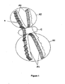
- the implant is in the form of 2 anchor zones (A1) and (A2) connected by a central zone (C) ( figure 1 ) and possibly intermediate connection areas such as in the closed position, the shape is substantially inscribed in a very elongated rectangle ( figure 2 ), and in open form corresponds more to a wider X shape due to the opening of the anchoring zones ( figure 3 ).
- the anchoring zones (A1), respectively (A2) are generally made each by 2 tabs (P1), respectively (P2) of length (L1), respectively (L2) ( figure 3 ).
- the transverse section of the implant is adapted to implantation sites, but preferentially flat in order to have good mechanical strength and reduced bulk (typically the thickness (e) is of the order of 1 to 2 mm) ( figure 1 ).
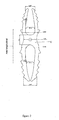
- the figure 2 describes the closed position with the different widths of the implant: (Lab) is the width of the central zone (C), (L1ab) and (L2ab) are the widths at the base of the anchoring zones respectively (A1) and (A2). These 3 widths can be equal or slightly different to fit the bone site. Typically the widths are of the order of 2 to 5 times the thickness (ie 2 to 10 mm). These dimensions are well adapted to the various indications of the hand and foot but are not limiting since they depend on the bone site of the operated patient.
- the anchoring zones (A1), (A2) are able to deviate by elastic effect or shape memory effect at their base, so that the maximum width in position open at the ends (La1) and (La2) ( figure 3 ) at least equal to the width of the base of the same anchorage zone in the closed position increased by at least 50%, or increased by at least 1.5 mm. That is, La1> L1ab + 50% or La1> L1ab + 1.5mm and that La2> L2ab + 50% or La2> L2ab + 1.5mm.
- This opening criterion is necessary in order to have enough hold in the bone.
- the legs (P1), (P2) are substantially straight at their base (about 1/3 to half their length) then rounded inwards at their end (about 1/3 to half their length).
- the right part of the tabs (P1), respectively (P2) has an angle (a1), respectively (a2) with the axis of the implant facing outwards ( figure 3 ), while in the closed position, this angle becomes the angle (b1), respectively (b2) negative turned inwards ( figure 2 ).
- the upper (towards the end) of the legs undergoes almost no particular deformation between the 2 forms open and closed.
- This particular geometrical arrangement allows that in the closed position the tabs touch almost at the end ( figure 2 ), and that the width at the end in the closed position (La1f), respectively (La2f) is less than the width of the base (L1ab), respectively (L2ab), which allows an easy introduction without distraction of the fragment distal bone and also allows to obtain the open / closed movement by a localized deformation at the base of the legs, that is to say leaving free the distal zone to introduce this zone into the bone.
- angles (a1), (a2) are preferentially between + 5 ° and + 25 ° and the angles (b1), (b2) between 0 ° and -15 °.
- the width of the ends of the anchoring zones in the closed position (La1f), respectively (La2f) is lower than the width of the base of said areas (L1ab), respectively (L2ab) decreased by 20%: La1f ⁇ L1ab-20 % and La2f ⁇ L2ab-20%.
- the legs or the anchoring zones are thus "articulated" at their base, and can therefore be held in closed position by a support or better a clamp, positioned at a suitable location defined in particular in the case of an elastic material (for a shape memory material, this is not necessarily necessary since the shape does not change until the activation temperature is reached), this clip not covering more than half the length of the tabs, which allows an introduction of the implant of at least half in its housing.
- a support or better a clamp positioned at a suitable location defined in particular in the case of an elastic material (for a shape memory material, this is not necessarily necessary since the shape does not change until the activation temperature is reached), this clip not covering more than half the length of the tabs, which allows an introduction of the implant of at least half in its housing.
- the tangent internal side end of the tabs (P1), respectively (P2) in the open position makes an angle ( ⁇ 1), respectively ( ⁇ 2) with the longitudinal axis of the implant close to 0 °, to have a good bone contact area over the entire length of the tab in the open position and prevent only the ends touching the bone ( figure 3 ).
- the implant In the implantation site, at body temperature, the implant can still be in the closed position, or parallel or semi-open tabs, so that the force exerted by the opening of the tabs is transmitted to the level of the bone and ensures a good anchorage.
- the elasticity or the memory of the part must make it possible to pass from the closed form (typically width 2 to 4 mm according to the size of the site) to an open form with a significant movement (+1,5 about +3 mm).
- the force of expansion of the legs (or swelling of the olive) must be significant: typically 1 to 3 kg for arthrodesis extremities (force measured at 37 ° C in the locked introduction position), without being excessive It is important that the legs can not open fully and that the bone resists in order to really have a holding force.
- the tabs (P1), (P2) or fins may have a rough surface or better notches (D) ( figure 3 ) on their external surfaces intended to impact the cancellous bone and to exert a good anchorage.
- the typical height of these notches (H1), (H2) is of the order of 0.5 mm.
- the opening of the legs must be at least 1.5 times this height to ensure a real impaction of the notches in the bone, 1.5 mm.
- the legs (P1), (P2) may also have a surface covered with an osseointegrating coating such as hydroxyapatite (PAH) to facilitate anchoring.
- PHA hydroxyapatite
- the ends of the legs (P1), resp. (P2) are beveled at an angle inward with respect to the longitudinal axis of the implant (W1), resp. (W2) ( figure 3 ). This angle is typically between -20 ° and -40 °.
- notches (D1) or (D2) on the outer side of the tabs (P1) resp. (P2) are used to position a clamping and insertion clamp at the base of the legs (P1), (P2) ( figure 3 ).
- These notches are asymmetrical pair of legs and their spacing (d) is the same on the legs (P1) that on the legs (P2).
- the central zone (C) must have a minimum length (Lc) equal to the length (d) between the notches (D1), respectively (D2), so that even in case of movement of the implant during the final impaction this area (C) remained in the focus of arthrodesis and performs its function of resistance.
- an orifice (Gold) in this central zone for positioning a holding pin to avoid possible migration of the implant at the time of the final impaction.
- this central zone can be angulated by an angle (Ag) defined between the two main planes formed by the tabs (P1) on the one hand and (P2) on the other hand to adapt to the surgical constraints of adjustment of the position of the arthrodesis.
- the angle (Ag) is between 0 ° (flat position typically for an index) and 30 ° (typically for a 5th finger)
- the implant is made of a superelastic nitinol alloy (nickel-titanium in the proportion 55.8% by weight nickel and 44.2% by titanium )
- the length of the central zone (C) is 3 mm, which allows a small offset during closing, without affecting the shear strength. To accommodate the surgeon's choice, this central area can be angled (typically flat or 15 ° or 25 °)
- the width of the proximal base L1 ab of 3.8 mm and of the distal base L2ab is 3.0 mm.
- the opening of the tabs (P1), respectively (P2) is 2.5 mm, respectively 2.2 mm, that is to say that La1 is 6.3 mm and La2 is 5.2 mm.
- the right portion is about 45% of the total length
- notches of height 0.5 mm are distributed on the tabs (1 notch every 0.8 mm)
- the rounded design of the anchoring zones makes it possible to obtain in the open form a maximized contact surface over the entire length, with an impaction effect in the cancellous bone, and therefore a packing effect of the cancellous bone.
Landscapes
- Health & Medical Sciences (AREA)
- Orthopedic Medicine & Surgery (AREA)
- Life Sciences & Earth Sciences (AREA)
- Surgery (AREA)
- Animal Behavior & Ethology (AREA)
- General Health & Medical Sciences (AREA)
- Biomedical Technology (AREA)
- Heart & Thoracic Surgery (AREA)
- Engineering & Computer Science (AREA)
- Veterinary Medicine (AREA)
- Public Health (AREA)
- Medical Informatics (AREA)
- Neurology (AREA)
- Nuclear Medicine, Radiotherapy & Molecular Imaging (AREA)
- Molecular Biology (AREA)
- Oral & Maxillofacial Surgery (AREA)
- Transplantation (AREA)
- Cardiology (AREA)
- Vascular Medicine (AREA)
- Prostheses (AREA)
- Surgical Instruments (AREA)
- Materials For Medical Uses (AREA)
Description
- L'invention se rattache au secteur technique des implants orthopédiques, notamment pour arthrodèses et ostéosynthèses.
- On rappelle qu'un implant d'ostéosynthèse doit servir à maintenir en place deux (ou plus) parties d'un même os fracturé ou coupé par une opération de chirurgie (ostéotomie), le temps nécessaire à la consolidation de cet os (typiquement 3 mois).
- On rappelle qu'une arthrodèse est le blocage d'une articulation par voie chirurgicale pour souder deux os en un seul, au moyen d'un dispositif d'ostéosynthèse.
- On rappelle que le but de toute ostéosynthèse et particulièrement dans le cas d'une arthrodèse est d'obtenir une très bonne stabilité aussi bien primaire que secondaire afin d'obtenir la consolidation dans les meilleures conditions, c'est-à-dire dans la position choisie par le chirurgien, en minimisant les problèmes de douleur postopératoire et les oedèmes, et en raccourcissant autant que faire se peut le temps de consolidation.
- Pour ce résultat, la stabilité de l'ostéosynthèse liée à l'implant est critique. De plus, l'implant doit également apporter et maintenir une légère compression sur les parties d'os à fusionner, ce qui facilite cette consolidation.
- Différentes solutions techniques ont été proposées, pour réaliser une arthrodèse, notamment au niveau des extrémités (pied, main, poignet, cheville, ...).
- On peut citer, par exemple, des agrafes basiques qui n'assurent pas un bon maintien pendant la consolidation, et des agrafes à mémoire de forme qui permettent de mettre en compression les deux parties d'os à consolider, ce qui correspond au but recherché.
Toutefois, pour obtenir une stabilité satisfaisante, il est nécessaire de mettre deux, voire trois agrafes, dans des plans différents. Il en résulte un encombrement important, ce qui limite les applications, notamment sur des petits os (par exemple au niveau des doigts ou des orteils). - Il est également courant d'utiliser des plaques et vis extramédullaires ou extra osseuses, qui nécessitent également un encombrement relativement important et ne peuvent être utilisées sur les phalanges terminales des doigts (arthrodèse interphalangienne distale par exemple). Par ailleurs la stabilité à moyen terme de ces systèmes n'est pas toujours au rendez-vous (débricolage du montage).
- Certains types de vis peuvent être utilisés en intramédullaire, mais dans ce cas, la voie d'abord nécessite un abord pulpaire ce qui peut générer des complications graves (sepsis, ...) et un inconfort pour le patient.
- On peut également utiliser des broches qui présentent un encombrement réduit. Toutefois la stabilité obtenue n'est pas satisfaisante (problèmes de migration) et il est généralement nécessaire de procéder au retrait après consolidation. De plus avec de tels dispositifs, le patient ne peut immerger le doigt ou l'orteil traité puisque la broche est en général débouchante à l'extérieur de la peau.
- Il existe pour des os longs (tibia, fémur, humérus, ....) des systèmes d'ostéosynthèse intramédullaires. On connaît par exemple les clous centromédullaires vérouillables. Outre que la technique de vérouillage est difficile, ils ne peuvent être miniaturisés pour la chirurgie des extrémités (main et pied).
- Enfin il existe des dispositifs intramédullaires à mémoire de forme permettant de résoudre une partie de la problématique de l'arthrodèse ou de l'ostéosynthèse des petits fragments : par exemple les solutions décrites dans le brevet 2 846 545 ou le brevet 2 884 406.
- Le brevet 2 846 545 décrit un dispositif en H qui s'ouvre dans le corps en forme de X, grâce à l'utilisation de la mémoire de forme réglée vers 37°C, chaque patte étant implantée dans un trou calibré.
- En pratique un tel système ne permet pas une introduction correcte dans l'os. En effet, la réalisation de 2 trous parallèles est très difficile dans une phalange du fait de la taille et surtout les pattes parallèles ont tendance à s'ouvrir naturellement lors de l'introduction et ont plutôt ce faisant un effet de distraction des deux fragments que de mise en compression.
- Par ailleurs, l'utilisation de la mémoire de forme est très limitative par les contraintes qu'elle génère pour les chirurgiens, notamment de gestion de la température : il faut impacter l'implant dans l'os dans leur phase froide fermée avant qu'ils s'ouvrent à la température du bloc. Ceci nécessite de mettre l'implant dans un support, de le stocker au froid et d'aller très vite pour l'implanter.
- Enfin les pattes étant droites conduisent dans leur forme ouverte à créer un appui ponctuel à leur extrémité qui n'apporte pas une bonne tenue et peut abîmer l'os.
- Le brevet 2 884 406 présente un système qui permet une introduction facilité soit par la forme (oeil), soit par un support ou une pince qui maintient fermées les pattes de l'implant pendant l'introduction.
- Néanmoins, ces systèmes ne fonctionnent pas de manière très fiables, car ils ne définissent pas les critères optimaux permettant une bonne introduction dans l'os et un bon ancrage : les zones d'ancrage ont toujours tendance à s'ouvrir trop tôt, ce qui bloque l'introduction
- L'invention s'est fixée pour but de remédier à tous ces inconvénients d'une manière simple, fiable, efficace et rationnelle.
- Le problème que se propose de résoudre l'invention est de définir les critères de réussite pour un implant intramédullaire, facile à poser et efficace pour générer une stabilité primaire et secondaire du foyer d'ostéosynthèse ou d'arthrodèse grâce à sa rigidité et à sa composante de compression.
- L'implant de l'invention est caractérisé par le fait qu'il comprend deux zones d'ancrage osseux de part et d'autre d'une zone rigide de stabilité, résistante au cisaillement, ces deux zones d'ancrage présentant à leur base une possibilité de réformation important (notamment par élasticité) et un design tels qu'elles peuvent adopter une position fermée (notamment grâce à une pince adaptée serrée à leur base) pour une introduction facile dans un trou centromédullaire calibré (réalisé avec un instrument adéquat), et qu'elles présentent dans le site osseux de part cette configuration particulière la possibilité de réaliser l'impaction finale sans effet distracteur sur l'os et présente une expansion suffisante pour assurer une bonne accroche dans l'os.
- Les zones d'ancrage peuvent se déformer à leur base par élasticité, superélasticité ou mémoire de forme et sont typiquement constituées par des branches ou pattes, éventuellement reliées (forme en olive ou ballon de rugby). Ces branches présentent dans la forme ouverte un angle positif vers l'extérieur à leur base et sont courbées vers l'intérieur vers leur extrémité tandis quand forme fermée, l'angle à la base est inversé, c'est-à-dire négatif ou tourné vers l'intérieur ce qui permet d'avoir la largeur au niveau des extrémités (côté impaction) plus fine que leur base afin de ne pas risquer de s'impacter dans l'os et de bloquer la pénétration de l'implant.
- L'invention trouve une application particulièrement avantageuse, qui ne saurait toutefois être considérée comme limitative, pour la réalisation des arthrodèses au niveau des phalanges des doigts et des orteils, notamment pour les articulations interphalangiennes proximales et distales dans la main et le pied.
- L'ensemble est implantable par voie dorsale (ou éventuellement latérales ou palmaire/plantaire), mais sans abord pulpaire, ce qui minimise les risques d'infection et améliore le confort patient.
- Pour tenir compte des caractéristiques anatomiques, les zones d'ancrages sont reliées à la zone médiane servant de résistance (notamment au cisaillement) au niveau du foyer d'ostéosynthèse par des zones de liaisons plus ou moins longues, et la zone centrale peut présenter une angulation pour s'adapter aux caractéristiques de l'arthrodèse recherchée.
- Le matériau constitutif de l'implant objet de l'invention doit permettre une certaine ouverture minimale des zones d'ancrage une fois l'implant dans le corps. Il peut donc s'agir de n'importe quel matériau implantable suffisamment élastique tel que de l'acier inoxydable, du titane, un matériau biorésorbable tel que l'acide polylactide PLLA ...
Préférentiellement, l'implant objet de l'invention est réalisé à partir d'un matériau à mémoire de forme utilisé pour sa propriété de superélasticité (ou élasticité liée à la transformation de phase austénite martensite sous contrainte) qui présente la plus grande plage d'élasticité connue (jusqu'à 8% en allongement élastique équivalent en traction pour un implant en Nitinol, alliage de Nickel - Titane comprenant environ 55,5 à 56% en poids de Nickel, le reste en titane). - L'utilisation d'un matériau présentant une mémoire de forme thermique vers 37°C est également possible.
- L'invention est exposée ci-après plus en détail à l'aide des figures et dessins annexés dans lesquels :
- La
figure 1 présente un exemple d'implant selon l'invention dans sa position totalement ouverte, en 3 dimensions. - La
figure 2 présente ce même exemple dans sa position fermée d'introduction, dans son plan principal, - La
figure 3 présente un exemple d'implant selon l'invention dans sa position totalement ouverte, dans son plan principal. - La
figure 4 présente un exemple d'implant coudé selon l'invention dans sa position totalement ouverte - La
figure 5 (5a à 5f) présente la séquence d'implantation : fermé, introduit à moitié toujours contraint, introduit complètement d'un côté (libre dans l'os), et la même séquence de l'autre côté. - L'implant se présente sous la forme de 2 zones d'ancrages (A1) et (A2) reliées par une zone centrale (C) (
figure 1 ) et éventuellement des zones de liaison intermédiaires telles que en position fermée, la forme soit sensiblement inscrite dans un rectangle très allongé (figure 2 ), et en forme ouverte corresponde plus à une forme en X plus large du fait de l'ouverture des zones d'ancrage (figure 3 ). - Les zones d'ancrages (A1), respectivement (A2) sont réalisées en général chacune par 2 pattes (P1), respectivement (P2) de longueur (L1), respectivement (L2) (
figure 3 ). - La section transverse de l'implant est adaptée aux sites d'implantation, mais préférentiellement méplate afin d'avoir une bonne résistance mécanique et un encombrement réduit (typiquement l'épaisseur (e) est de l'ordre de 1 à 2 mm) (
figure 1 ). - La
figure 2 décrit la position fermée avec les différentes largeurs de l'implant : (Lab) est la largeur de la zone centrale (C), (L1ab) et (L2ab) sont les largeurs à la base des zones d'ancrage respectivement (A1) et (A2). Ces 3 largeurs peuvent être égales ou légèrement différentes pour s'adapter au site osseux. Typiquement les largeurs sont de l'ordre de 2 à 5 fois l'épaisseur (soit 2 à 10 mm). Ces dimensions sont bien adaptées aux différentes indications de la main et du pied mais ne sont pas limitatives puisqu'elles dépendent du site osseux du patient opéré. - Les zones d'ancrages (A1), (A2) sont aptes à s'écarter par effet élastique ou par effet mémoire de forme à leur base, afin que la largeur maximale en position ouverte aux extrémités (La1) et (La2) (
figure 3 ) soit au moins égale à la largeur de la base de la même zone d'ancrage en position fermée augmentée de 50% minimum, ou augmentée de 1,5 mm minimum. C'est-à-dire que La1 > L1ab + 50% ou La1 > L1ab + 1,5 mm et que La2 > L2ab + 50% ou La2 > L2ab + 1,5 mm. - Ce critère d'ouverture est nécessaire afin d'avoir suffisamment de tenue dans l'os.
- Ainsi que le décrit la
figure 3 , les pattes (P1), (P2) sont sensiblement droites à leur base (sur environ 1/3 à la moitié de leur longueur) puis de formes arrondies vers l'intérieur à leur extrémité (sur environ 1/3 à la moitié de leur longueur). En position ouverte la partie droite des pattes (P1), respectivement (P2) présente un angle (a1), respectivement (a2) avec l'axe de l'implant tourné vers l'extérieur (figure 3 ), positif, tandis qu'en position fermée, cet angle devient l'angle (b1), respectivement (b2) négatif tourné vers l'intérieur (figure 2 ). La partie supérieure (vers l'extrémité) des pattes ne subit quasiment pas de déformation particulière entre les 2 formes ouverte et fermée.
Cette disposition géométrique particulière permet qu'en position fermée les pattes se touchent quasiment à l'extrémité (figure 2 ), et que la largeur au niveau de l'extrémité en position fermée (La1f), respectivement (La2f) soit inférieure à la largeur de la base (L1ab), respectivement (L2ab), ce qui permet une introduction facile sans distraction du fragment osseux distal et permet également d'obtenir le mouvement ouvert/fermée par une déformation localisée à la base des pattes, c'est-à-dire en laissant libre la zone distale pour pouvoir introduire cette zone dans l'os. - Afin d'obtenir à la fois une introduction aisée et un mouvement suffisant d'ouverture, les angles (a1), (a2) sont préférentiellement compris entre +5° et +25° et les angles (b1), (b2) entre 0° et-15°.
- Préférentiellement la largeur des extrémités des zones d'ancrage en position fermée (La1f), respectivement (La2f) est plus faible que la largeur de la base desdites zones (L1ab), respectivement (L2ab) diminuée de 20% : La1f< L1ab-20% et La2f< L2ab-20%.
- Les pattes ou les zones d'ancrage sont ainsi « articulées » à leur base, et peuvent donc être maintenues en position fermées par un support ou mieux une pince, positionnée à un endroit adéquat défini notamment dans le cas d'un matériau élastique (pour un matériau à mémoire de forme, cela n'est pas forcément nécessaire puisque la forme n'évolue pas tant que la température d'activation n'est pas atteinte), cette pince ne couvrant pas plus de la moitié de la longueur des pattes, ce qui permet une introduction de l'implant d'au moins la moitié dans son logement.
- La tangente côté interne en extrémité des pattes (P1), respectivement (P2) en position ouverte fait un angle (β1), respectivement (β2) avec l'axe longitudinal de l'implant proche de 0°, afin d'avoir une bonne surface de contact osseux sur toute la longueur de la patte en position ouverte et éviter que seules les extrémités touchent l'os (
figure 3 ). - Dans le site d'implantation, à la température du corps, l'implant peut encore être en position fermée, ou pattes parallèles ou semi-ouvert, afin que l'effort exercé par l'ouverture des pattes se transmette au niveau de l'os et assure un bon ancrage.
- Cette disposition « en olive » des pattes, associée à une « articulation » de la base et associée à une introduction minimale de la moitié de leur longueur permet de finir l'impaction, une fois la pince enlevée.
- Afin de garantir un bon fonctionnement, l'élasticité ou la mémoire de la pièce doit permettre de passer de la forme fermée (typiquement largeur 2 à 4 mm selon la taille du site) à une forme ouverte avec un mouvement significatif (+1,5 à + 3 mm environ).
De même la force d'expansion des pattes (ou de gonflement de l'olive) doit être significative : typiquement 1 à 3 kg pour une arthrodèse des extrémités (force mesurée à 37°C en position d'introduction bloquée), sans être excessive : il importe que les pattes ne puissent pas s'ouvrir totalement et que l'os résiste afin d'avoir réellement une force de maintien. - Les pattes (P1), (P2) ou ailettes peuvent présenter une surface rugueuse ou mieux des crans (D) (
figure 3 ) sur leurs surfaces externes destinées à s'impacter dans l'os spongieux et à exercer un bon ancrage. La hauteur typique de ces crans (H1), (H2) est de l'ordre de 0,5 mm.
L'ouverture des pattes doit être au minimum de 1,5 fois cette hauteur afin d'assurer une impaction réelle des crans dans l'os, soit 1,5 mm. - Les pattes (P1), (P2) peuvent également présenter une surface recouverte d'un revêtement ostéointégrateur telle que l'hydroxyhapatite (HAP) destinée à faciliter l'ancrage.
- Afin de faciliter l'introduction dans l'os, les extrémités des pattes (P1), resp. (P2) sont biseautées avec un angle vers l'intérieur par rapport à l'axe longitudinal de l'implant (W1), resp. (W2) (
figure 3 ). Cet angle est typiquement compris entre -20° et -40°. - Par essai sur cadavres frais, et expérience, il a été déterminé un niveau optimal de la force avec un minimum permettant d'ancrer les crans dans l'os spongieux et une force maximale pour être sur de ne pas détériorer le site d'implantation
- Après tests et expérience, il a été trouvé une zone idéale de maximum 20% de la limite élastique de l'os mesurée en forme fermée bloquée à 37°C , ce qui compte tenu des dimensions de l'implant conduit à des valeurs maximales de l'ordre de 3 kg, et la nécessité d'un abaissement rapide dès que l'ancrage est obtenu, soit une force divisée par 2 en position semi-ouverte (une force de 0,5 à 1,5 kg permet un bon maintien).
En effet si la force d'ouverture est supérieur à environ 3 kg, l'introduction dans l'os devient beaucoup plus difficile, voir impossible dès 4 kg.
Enfin afin de garantir une non détérioration du site, il est nécessaire que la force devienne négligeable pour une ouverture quasi-complète.
Ces valeurs sont indicatives et dépendent du site d'arthrodèse et de la qualité osseuse. - Sur une version de l'invention, des crans (D1), resp.(D2) côté externe aux pattes (P1), resp. (P2) permettent de positionner une pince de serrage et d'introduction à la base des pattes (P1), (P2) (
figure 3 ). Ces crans sont asymétriques par paire de pattes et leur écartement (d) est le même sur les pattes (P1) que sur les pattes (P2). - La zone centrale (C) doit avoir une longueur minimale (Lc) égale à la longueur (d) entre les crans (D1), respectivement (D2), afin que même en cas de mouvement de l'implant lors de l'impaction finale cette zone (C) resté dans le foyer d'arthrodèse et assure sa fonction de résistance.
Dans une version de l'invention, il est prévu un orifice (Or) dans cette zone centrale permettant de positionner une broche de maintien pour éviter une éventuelle migration de l'implant au moment de l'impaction finale. - Ainsi que le montre la
figure 4 , cette zone centrale peut être angulée d'un angle (Ag) défini entre les 2 plans principaux formés par les pattes (P1) d'une part et (P2) d'autre part pour s'adapter aux contraintes chirurgicales de réglage de la position de l'arthrodèse. Dans la majorité des cas, l'angle (Ag) est fixé entre 0° (position plate typiquement pour un index) et 30°(typiquement pour un 5e doigt) - A titre d'exemple une technique opératoire de l'implantation du dispositif de l'invention pour le cas d'un implant élastique ou superélastique est la suivante telle que décrit sur la
figure 5 : - Abord par voie dorsale
- Résection des cartilages et ostéophytes
- Perçage centromédullaire à l'aide d'un instrument adapté permettant de faire un trou calibré rectangle de largeur sensiblement (L1ab) ou (L2ab) et d'épaisseur sensiblement e (râpe adaptée)
- Fermeture à la pince côté P1 (
figure 5a ) - Introduction implant côté P1 à la moitié minimum (
figure 5b ) - Enlèvement pince
- Introduction totale côté P1 (
figure 5c ) - Fermeture à la pince côté P2 (
figure 5d ) - Mise en place de l'os côté P2 sur l'implant côté P2 à la moitié environ (
figure 5 e) Enlèvement de la pince - Impaction manuelle de l'os côté P2 sur l'os P1 (
figure 5f ) - Dans une forme de réalisation particulière, destinée à l'arthrodèse de l'InterPhalangienne Distale (main), l'implant est réalisé dans un alliage nitinol superélastique (nickel-titane dans la proportion 55,8% poids Nickel et 44,2% titane)
- La section de la zone centrale (C) est de Lab x e = 2,8 x 1,2 mm et les pattes sont dissymétriques pour s'adapter au mieux aux formes de l'os, minimiser la section métallique implantée et permettre une expansion suffisante pour un bon ancrage. La longueur des pattes est de L2=6,5 mm en distale (P2) et L1=9 mm en proximale (P1)
La longueur de la zone centrale (C) est de 3 mm, ce qui autorise un petit décalage lors de la fermeture, sans nuire à la résistance au cisaillement.
Pour s'adapter au choix du chirurgien, cette zone centrale peut être coudée (typiquement plate ou 15° ou 25°) - En position fermée, la largeur de la base proximale Ll ab de 3,8 mm et de la base distale L2ab est de 3,0 mm.
- L'ouverture des pattes (P1), respectivement (P2) est de 2,5 mm, respectivement 2,2 mm, c'est-à-dire que La1 vaut 6,3 mm et La2 vaut 5,2 mm.
En position ouverte l'angle à la base des pattes est de a1 =10° et a2=22°
La portion droite est d'environ 45% de la longueur totale
La courbure de l'extrémité distale des pattes est calculée pour que l'angle de la tangente à l'extrémité soit de β1= -5° et β2= -3° - En position fermée, l'angle à la base des pattes est bl=-4°, b2= -2°
Et la largeur à l'extrémité est La1f = 2,5 mm et La2f = 2,1 mm - Dans une forme de réalisation de l'invention, des crans de hauteur 0,5 mm sont réparties sur les pattes (1 cran tous les 0,8 mm environ)
- L'angle d'incidence de l'extrémité des pattes (crans compris) est de w1 = 33° et w2 = 24°, ce qui permet une introduction aisée sans effet distracteur entre les 2 morceaux d'os à ostéosynthéser
- Le dessin arrondi des zones d'ancrage permet d'obtenir en forme ouverte une surface de contact maximisée sur toute la longueur, avec un effet d'impaction dans l'os spongieux, et donc un effet de tassement du spongieux.
- Dans un autre exemple, plus adapté à une arthrodèse au niveau du pouce, les dimensions sont plutôt les suivantes :
- Largeurs fermées : L1ab = 6,5 mm, L2ab = 5 mm, avec une ouverture de 3 à 4mm environ pour obtenir : La1 = 11 mm et La2 = 8 mm et L1=13 mm et L2=9mm
Claims (11)
- Dispositif d'ostéosynthèse et d'arthrodèse intramédullaire pour la chirurgie orthopédique notamment de la main et du pied, de section principale sensiblement méplate, de forme première en H constituée de 2 zones d'ancrage (A1), (A2) comprenant chacune un jeu de pattes (P1), (P2) sensiblement parallèles reliés par une zone centrale (C ), forme en H dite forme fermée ou forme d'introduction sensiblement inscrite dans un rectangle allongé, et une forme ouverte dite implantée en X de largeur supérieure, caractérisée en ce que :- en forme ouverte les pattes (P1), (P2) forment à leur base sur le 1er tiers de leur longueur un angle par rapport à l'axe de l'implant (a1), (a2) vers l'extérieur compris entre 5° et 25°, et sont recourbées vers l'intérieur sur le dernier tiers de leur longueur (vers leur extrémité), pour que la tangente côté interne à l'extrémité forme un angle (β1), (β2) avec l'axe longitudinal de l'implant voisin de 0°,- en forme fermée les pattes (P1), (P2) forment à leur base sur le 1er tiers de leur longueur un angle (b1), (b2) vers l'intérieur compris entre -0° et -15°, sans modification notables sur le dernier tiers de leur longueur, pour que la largeur extérieure aux extrémités en forme fermée (La1f), respectivement (La2f) et sur environ la moitié de la longueur des pattes côté extrémités soit inférieure à la largeur de la base (L1ab), respectivement (L2ab) de ces zones d'ancrage (A1), (A2),- le passage de la forme fermée à la forme ouverte se fait préférentiellement par la déformation de la base des zones d'ancrage (A1), (A2).
- Dispositif selon la revendication 1 caractérisé en ce que la largeur aux extrémités de la forme ouverte (La1), respectivement (La2) est au moins égale à la largeur d'introduction fermée (L1ab), respectivement (L2ab) plus 50%, ou à la largeur d'introduction fermée (L1ab), respectivement (L2ab) + 1,5 mm.
C'est-à-dire La1 > L1ab + 50% ou La1 > L1ab + 1,5 mm et La2 > L2ab + 50% ou La2 > L2ab + 1,5 mm. - Dispositif selon l'une quelconque des revendications 1 à 2 caractérisé en ce que la largeur aux extrémités de la forme fermée (La1f), respectivement (La2f) soit inférieure à la largeur en forme fermée de la base (L1ab) de la zone d'ancrage (A1), respectivement (L2ab) de la zone d'ancrage (A2) diminuée de 20% : La1f< L1ab-20% et La2f< L2ab-20%.
- Dispositif selon l'une quelconque des revendications 1 à 3 caractérisé en ce que les extrémités de la zone à introduire sont biseautées vers l'intérieur pour faciliter l'introduction, en présentant un angle (W1), (W2) en position ouverte par rapport à l'axe de l'implant compris entre -20 et -40° vers l'intérieur.
- Dispositif selon l'une quelconque des revendications 1 à 4 caractérisé en ce que les 2 zones d'ancrage présentent des crans (D) sur la surface externe des pattes (P1), (P2) ou une surface rugueuse destinés à faciliter l'ancrage.
- Dispositif selon l'une quelconque des revendications 1 à 5 caractérisé en ce que les 2 zones d'ancrage sont reliées par une zone centrale (C) rigide apte à supporter les contraintes de cisaillement au niveau du foyer d'arthrodèse.
- Dispositif selon l'une quelconque des revendications 1 à 6 caractérisé en ce que la zone centrale (C) présente une angulation (Ag) entre les 2 zones d'ancrage (A1), (A2) permettant un réglage de la position osseuse de l'arthrodèse entre 0 et 30°.
- Dispositif selon l'une quelconque des revendications 1 à 7 caractérisé en ce qu'il est réalisé dans un matériau implantable, notamment en nitinol (nickel titane à mémoire de forme ou superélastique), en titane élastique ou en un matériau résorbable tel que l'acide polylactide PLLA, de sorte que le passage de la forme d'introduction fermée à la forme ouverte se fasse par élasticité, superélasticité ou mémoire de forme.
- Dispositif selon l'une quelconque des revendications 1 à 8 caractérisé en ce que il existe dans la moitié inférieure des zones d'ancrage une zone ou un logement de longueur (d) matérialisé par exemple par des crans externes (D1), (D2) permettant de positionner un instrument adéquat de fermeture et de maintien en position fermée.
- Dispositif selon l'une quelconque des revendications 1 à 9 caractérisé en ce que la longueur (Lc) de la zone centrale (C) est au moins égale à la longueur (d) du logement matérialisé par les crans (D1), (D2).
- Dispositif selon l'une quelconque des revendications 1 à 10 caractérisé en ce que il existe un orifice (Or) dans la zone centrale (C) perpendiculaire à la surface permettant de positionner un instrument ou une broche de maintien.
Priority Applications (1)
| Application Number | Priority Date | Filing Date | Title |
|---|---|---|---|
| EP10007388A EP2241290B1 (fr) | 2007-03-20 | 2008-03-14 | Dispositif d'osteosynthèse |
Applications Claiming Priority (2)
| Application Number | Priority Date | Filing Date | Title |
|---|---|---|---|
| FR0702003A FR2913876B1 (fr) | 2007-03-20 | 2007-03-20 | Dispositif d'osteosynthese |
| PCT/FR2008/050453 WO2008129214A2 (fr) | 2007-03-20 | 2008-03-14 | Dispositif d'osteosynthese |
Publications (2)
| Publication Number | Publication Date |
|---|---|
| EP2124833A2 EP2124833A2 (fr) | 2009-12-02 |
| EP2124833B1 true EP2124833B1 (fr) | 2010-08-04 |
Family
ID=38698178
Family Applications (2)
| Application Number | Title | Priority Date | Filing Date |
|---|---|---|---|
| EP10007388A Active EP2241290B1 (fr) | 2007-03-20 | 2008-03-14 | Dispositif d'osteosynthèse |
| EP08799857A Active EP2124833B1 (fr) | 2007-03-20 | 2008-03-14 | Dispositif d'osteosynthese |
Family Applications Before (1)
| Application Number | Title | Priority Date | Filing Date |
|---|---|---|---|
| EP10007388A Active EP2241290B1 (fr) | 2007-03-20 | 2008-03-14 | Dispositif d'osteosynthèse |
Country Status (10)
| Country | Link |
|---|---|
| US (5) | US8394097B2 (fr) |
| EP (2) | EP2241290B1 (fr) |
| JP (1) | JP5386376B2 (fr) |
| AT (2) | ATE476156T1 (fr) |
| AU (1) | AU2008240484B2 (fr) |
| CA (1) | CA2680512C (fr) |
| DE (1) | DE602008002061D1 (fr) |
| ES (2) | ES2385515T3 (fr) |
| FR (1) | FR2913876B1 (fr) |
| WO (1) | WO2008129214A2 (fr) |
Families Citing this family (67)
| Publication number | Priority date | Publication date | Assignee | Title |
|---|---|---|---|---|
| US8870836B2 (en) | 2003-07-15 | 2014-10-28 | Spinal Generations, Llc | Method and device for delivering medicine to bone |
| US8062270B2 (en) | 2003-07-15 | 2011-11-22 | Spinal Generations, Llc | Method and device for delivering medicine to bone |
| US7527611B2 (en) * | 2003-07-15 | 2009-05-05 | Spinal Generations, Llc | Method and device for delivering medicine to bone |
| FR2884406B1 (fr) | 2005-04-14 | 2008-10-17 | Memometal Technologies Soc Par | Dispositif d'osteosynthese intramedullaire de deux parties d'os, notamment de la main et/ou du pied |
| FR2913876B1 (fr) | 2007-03-20 | 2009-06-05 | Memometal Technologies Soc Par | Dispositif d'osteosynthese |
| FR2935601B1 (fr) * | 2008-09-09 | 2010-10-01 | Memometal Technologies | Implant intramedullaire resorbable entre deux os ou deux fragments osseux |
| US8668695B2 (en) * | 2008-10-15 | 2014-03-11 | Zimmer Gmbh | Intramedullary nail |
| FR2940760B1 (fr) | 2009-01-08 | 2010-12-31 | Memometal Technologies | Implant orthopedique pour arthroplastie digitale |
| FR2957244B1 (fr) * | 2010-03-09 | 2012-04-13 | Synchro Medical | Implant d'arthrodese |
| US9072564B2 (en) | 2010-06-02 | 2015-07-07 | Wright Medical Technology, Inc. | Hammer toe implant and method |
| US9498273B2 (en) | 2010-06-02 | 2016-11-22 | Wright Medical Technology, Inc. | Orthopedic implant kit |
| US8608785B2 (en) | 2010-06-02 | 2013-12-17 | Wright Medical Technology, Inc. | Hammer toe implant with expansion portion for retrograde approach |
| US9724140B2 (en) | 2010-06-02 | 2017-08-08 | Wright Medical Technology, Inc. | Tapered, cylindrical cruciform hammer toe implant and method |
| DE102010031349B4 (de) * | 2010-07-14 | 2015-02-05 | Waldemar Link Gmbh & Co. Kg | Fingergelenkprothese |
| US8834483B2 (en) * | 2010-10-04 | 2014-09-16 | Biomedical Enterprises, Inc. | Method and system for storing and inserting an implant |
| US10111690B2 (en) * | 2010-10-10 | 2018-10-30 | Orthopro Llc | Arthrodesis implant and buttressing apparatus and method |
| US20120089197A1 (en) * | 2010-10-10 | 2012-04-12 | Anderson Gregory S | Arthrodesis implant apparatus and method |
| US20130123862A1 (en) * | 2010-10-10 | 2013-05-16 | Gregory Anderson | Arthrodesis implant and buttressing apparatus and method |
| US8591545B2 (en) * | 2011-03-25 | 2013-11-26 | Smith & Nephew, Inc. | Flat suture anchor |
| FR2980097B1 (fr) * | 2011-09-16 | 2014-01-10 | Georges Kehyayan | Dispositif d'osteosynthese |
| US9724138B2 (en) * | 2011-09-22 | 2017-08-08 | Arthrex, Inc. | Intermedullary devices for generating and applying compression within a body |
| WO2013055824A1 (fr) * | 2011-10-10 | 2013-04-18 | William Casey Fox | Implant osseux à forme variable permettant une cicatrisation accélérée |
| US9554914B2 (en) * | 2011-12-12 | 2017-01-31 | Wright Medical Technology, Inc. | Fusion implant |
| US10405903B1 (en) | 2012-05-04 | 2019-09-10 | Xtraverse, LLC | Fasteners with shape changing zigzag structures and methods using same |
| US9138274B1 (en) | 2012-05-04 | 2015-09-22 | Xtraverse, LLC | Fasteners with shape changing bellows and methods using same |
| US10653462B2 (en) * | 2012-05-22 | 2020-05-19 | Lifenet Health | Cortical bone pin |
| US9775630B2 (en) | 2012-05-24 | 2017-10-03 | Orthopro Llc | Systems and methods for implanting surgical implants |
| US9603644B2 (en) | 2012-08-07 | 2017-03-28 | Spinal Generations, Llc | Methods and devices for delivery of medicine to bone |
| CN102772240B (zh) * | 2012-08-21 | 2014-07-09 | 徐永清 | 一种骨内自复形高效骨折复位与固定装置 |
| US8945232B2 (en) | 2012-12-31 | 2015-02-03 | Wright Medical Technology, Inc. | Ball and socket implants for correction of hammer toes and claw toes |
| USD720072S1 (en) | 2013-02-06 | 2014-12-23 | Biomedical Enterprises, Inc. | Orthopedic implant |
| US9724139B2 (en) | 2013-10-01 | 2017-08-08 | Wright Medical Technology, Inc. | Hammer toe implant and method |
| WO2015061556A2 (fr) * | 2013-10-23 | 2015-04-30 | Extremity Medical Llc | Dispositifs et procédés pour fixation d'os à l'aide d'un implant à fixation intramédullaire |
| CN106102612B (zh) | 2013-11-11 | 2020-07-21 | 阿特雷克斯公司 | 用于在身体内产生并施加压紧的螺钉 |
| US10016198B2 (en) | 2014-11-13 | 2018-07-10 | Arthrex, Inc. | Staples for generating and applying compression within a body |
| CN106413606B (zh) | 2013-11-13 | 2020-03-13 | 阿特雷克斯公司 | 用于在体内产生并施加压紧的髓内装置 |
| US9522022B2 (en) * | 2013-11-18 | 2016-12-20 | Biomedical Enterprises, Inc. | Method and appparatus for an intramedullary implant and method of implantation therefor |
| US9636155B2 (en) | 2013-11-18 | 2017-05-02 | Biomedical Enterprises, Inc. | Method and apparatus for an intramudullary implant and method of implantation thereof |
| US9474561B2 (en) | 2013-11-19 | 2016-10-25 | Wright Medical Technology, Inc. | Two-wire technique for installing hammertoe implant |
| US9999454B2 (en) * | 2013-12-05 | 2018-06-19 | A&E Advanced Closure Systems, Llc | Bone plate system and method |
| US9545274B2 (en) * | 2014-02-12 | 2017-01-17 | Wright Medical Technology, Inc. | Intramedullary implant, system, and method for inserting an implant into a bone |
| US9498266B2 (en) | 2014-02-12 | 2016-11-22 | Wright Medical Technology, Inc. | Intramedullary implant, system, and method for inserting an implant into a bone |
| US10653470B2 (en) | 2014-02-19 | 2020-05-19 | Spinal Generation, LLC | Compressible mixing and delivery system for medical substances |
| FR3018441B1 (fr) * | 2014-03-11 | 2016-04-01 | Novastep | Implant chirurgical pour une fusion entre deux portions d’os et ancillaire de serrage pour serrer un tel implant chirurgical |
| FR3021524A1 (fr) | 2014-06-02 | 2015-12-04 | Small Bone Innovations Internat | Tige d'ancrage metacarpien, notamment pour une prothese trapezo-metacarpienne |
| WO2016043751A1 (fr) | 2014-09-18 | 2016-03-24 | Wright Medical Technology, Inc. | Implant pour orteil en marteau et instrument |
| US9615863B2 (en) | 2014-10-22 | 2017-04-11 | Spinal Generations, Llc | Multichannel cannula for kyphoplasty and method of use |
| USD760894S1 (en) | 2014-11-13 | 2016-07-05 | Biomedical Enterprises, Inc. | Orthopedic implant retaining device |
| USD745163S1 (en) * | 2014-11-13 | 2015-12-08 | Biomedical Enterprises, Inc. | Orthopedic implant |
| USD756513S1 (en) | 2014-11-13 | 2016-05-17 | Biomedical Enterprises, Inc. | Orthopedic implant insertion device |
| CA2889595C (fr) * | 2014-12-19 | 2018-01-16 | Wright Medical Technology, Inc. | Ancrage intramedullaire pour arthrodese interphalangienne |
| US10898249B2 (en) | 2015-01-28 | 2021-01-26 | Arthrex, Inc. | Self-compressing screws for generating and applying compression within a body |
| US9757168B2 (en) | 2015-03-03 | 2017-09-12 | Howmedica Osteonics Corp. | Orthopedic implant and methods of implanting and removing same |
| US10123831B2 (en) | 2015-03-03 | 2018-11-13 | Pioneer Surgical Technology, Inc. | Bone compression device and method |
| US9907585B2 (en) | 2015-04-30 | 2018-03-06 | William Casey Fox | Bone intramedullary fixation scaffold |
| US10130358B2 (en) | 2015-10-07 | 2018-11-20 | Arthrex, Inc. | Devices for controlling the unloading of superelastic and shape memory orthopedic implants |
| FR3048871A1 (fr) | 2016-03-16 | 2017-09-22 | Neosteo | Implant medical et ensemble comprenant un tel implant medical et un prehenseur dudit implant |
| US10470807B2 (en) | 2016-06-03 | 2019-11-12 | Stryker European Holdings I, Llc | Intramedullary implant and method of use |
| CN118105213A (zh) | 2018-03-15 | 2024-05-31 | 斯皮诺尔有限公司 | 植入件 |
| CN112367937A (zh) | 2018-06-29 | 2021-02-12 | 先锋外科技术公司 | 骨板系统 |
| EP3603574B1 (fr) | 2018-08-03 | 2024-04-17 | Keri Medical SA | Dispositif d'ancrage osseux |
| US11877779B2 (en) | 2020-03-26 | 2024-01-23 | Xtant Medical Holdings, Inc. | Bone plate system |
| WO2021231329A1 (fr) | 2020-05-11 | 2021-11-18 | Gensano Llc | Implant osseux à canule |
| RU2750359C2 (ru) * | 2020-11-02 | 2021-06-28 | Общество с ограниченной ответственностью "КОНМЕТ" | Стержень для интрамедуллярного остеосинтеза и способ изготовления стержня для интрамедуллярного остеосинтеза |
| US20250177017A1 (en) * | 2022-03-18 | 2025-06-05 | Toetal Solutions Inc. | Interphalangeal joint implant methods and apparatus |
| US12064156B2 (en) | 2023-01-09 | 2024-08-20 | John F. Krumme | Dynamic compression fixation devices |
| US12446938B2 (en) | 2023-01-12 | 2025-10-21 | DePuy Synthes Products, Inc. | Orthopedic fixation system |
Family Cites Families (250)
| Publication number | Priority date | Publication date | Assignee | Title |
|---|---|---|---|---|
| US321389A (en) | 1885-06-30 | Combined nail and screw | ||
| US1095054A (en) | 1913-08-26 | 1914-04-28 | Robert Wiesenfeld | Fish-tongs. |
| US1517334A (en) | 1924-02-28 | 1924-12-02 | Eda L Young | Comb |
| US1893864A (en) | 1932-02-26 | 1933-01-10 | Kocher Philip | Comb |
| US2128005A (en) | 1937-06-25 | 1938-08-23 | Albert H Tinnerman | Hammer-driven supporting device |
| US2208848A (en) | 1937-10-18 | 1940-07-23 | Superior Fastener Corp | Connector |
| US2531911A (en) | 1945-12-15 | 1950-11-28 | Palnut Company | Shield can with spring attachment means |
| US2580821A (en) | 1950-10-21 | 1952-01-01 | Nicola Toufick | Spring impactor bone plate |
| US2984248A (en) | 1958-04-04 | 1961-05-16 | Delamere Co Inc | Light weight hair retaining fine tooth metal comb |
| US3338689A (en) | 1965-09-13 | 1967-08-29 | Marvin E Hetzel | Chain form clip |
| US3466669A (en) * | 1966-09-20 | 1969-09-16 | Univ Iowa | Intramedullary finger joint prosthesis |
| NL132715C (fr) * | 1967-01-06 | |||
| US3646654A (en) | 1968-02-12 | 1972-03-07 | Joseph J Cervenka | Clip |
| US3593342A (en) * | 1969-01-27 | 1971-07-20 | Cutter Lab | Prosthetic joint |
| US3681786A (en) * | 1970-07-13 | 1972-08-08 | Medical Eng Corp | Solid human prosthesis of varying consistency |
| GB1320956A (en) * | 1970-10-09 | 1973-06-20 | St Peters Research Ltd | Prosthetic joints |
| CH542624A (de) | 1971-10-08 | 1973-10-15 | Mathys Robert | Fingergelenkprothese |
| US3824631A (en) * | 1973-05-11 | 1974-07-23 | Sampson Corp | Bone joint fusion prosthesis |
| US3875594A (en) | 1973-08-27 | 1975-04-08 | Dow Corning | Surgically implantable prosthetic joint having load distributing flexible hinge |
| USD243716S (en) * | 1975-07-24 | 1977-03-15 | Richards Manufacturing Company, Inc. | Great toe prosthesis |
| IL48826A (en) | 1976-01-13 | 1978-08-31 | Aginsky Yacov | Intramedullary compression nail for the treatment of bone fractures |
| US4158893A (en) | 1976-10-12 | 1979-06-26 | Swanson Alfred B | Protective sleeve for implantable prosthesis and method of protecting the prosthesis |
| US4204284A (en) * | 1977-11-16 | 1980-05-27 | Lord Corporation | Joint prosthesis with contoured pin |
| US4276660A (en) * | 1979-05-25 | 1981-07-07 | Laure Prosthetics, Inc. | Carpometacarpal thumb joint |
| ZA80327B (en) * | 1979-08-23 | 1981-09-30 | U Mennen | Internal fixation device for bone fractures |
| FR2484826B1 (fr) | 1980-06-19 | 1985-10-04 | Gauthier Georges | Perfectionnement aux protheses articulaires |
| US4485816A (en) | 1981-06-25 | 1984-12-04 | Alchemia | Shape-memory surgical staple apparatus and method for use in surgical suturing |
| GB2119655B (en) | 1982-05-06 | 1985-05-15 | Nat Res Dev | Endoprosthesis] |
| USD277784S (en) * | 1982-06-25 | 1985-02-26 | Sutter Biomedical, Inc. | Lesser toe metatarsal phalangeal implant |
| USD277509S (en) * | 1982-07-01 | 1985-02-05 | Sutter Biomedical Inc. | Great toe metatarsal phalangeal implant |
| USD284099S (en) * | 1983-03-14 | 1986-06-03 | Sutter Bio-Medical, Inc. | Great toe metatarsal phalangeal implant |
| US4522200A (en) | 1983-06-10 | 1985-06-11 | Ace Orthopedic Company | Adjustable intramedullar rod |
| US5190546A (en) * | 1983-10-14 | 1993-03-02 | Raychem Corporation | Medical devices incorporating SIM alloy elements |
| JPS60145133A (ja) | 1984-01-09 | 1985-07-31 | 工業技術院長 | 骨接続具 |
| US4634382A (en) * | 1984-06-07 | 1987-01-06 | Molten Corp. | Attachment for dental prosthesis |
| USD291731S (en) * | 1985-05-08 | 1987-09-01 | Zimmer, Inc. | Prosthetic joint implant for a finger or toe or the like |
| EP0278184A1 (fr) * | 1987-02-11 | 1988-08-17 | Thierry Hermann | Prothèse d'articulation, en particulier pour articulation de doigt |
| US4871367A (en) | 1987-09-03 | 1989-10-03 | Sutter Biomedical Corporation | Surgically implanted prosthesis |
| FR2620932A1 (fr) * | 1987-09-28 | 1989-03-31 | Saffar Philippe | Prothese d'articulation metacarpo-phalangienne ou interphalangienne de doigts |
| FR2622100B1 (fr) * | 1987-10-27 | 1991-02-15 | Barouk Louis | Implant prothetique articulaire a fixation temporaire |
| SE466732B (sv) | 1987-10-29 | 1992-03-30 | Atos Medical Ab | Ledprotes, innefattande en ledkropp mellan ett par tappar foer infaestning i ben |
| GB8803680D0 (en) | 1988-02-17 | 1988-03-16 | Fahmy N R M | Distraction compression spring system treatment of intra-articular fractures |
| US4905679A (en) | 1988-02-22 | 1990-03-06 | M P Operation, Inc. | Bone fracture reduction device and method of internal fixation of bone fractures |
| CH674705A5 (fr) | 1988-04-27 | 1990-07-13 | Sulzer Ag | |
| SE466936B (sv) | 1989-04-25 | 1992-05-04 | Branemark Per Ingvar | Foerankringselement foer uppbaerande av proteser |
| AU630183B2 (en) | 1989-04-25 | 1992-10-22 | Per-Ingvar Branemark | Anchoring element for supporting a joint mechanism of a finger or other reconstructed joint |
| US5108443A (en) | 1989-04-25 | 1992-04-28 | Medevelop Ab | Anchoring element for supporting a joint mechanism of a finger or other reconstructed joint |
| US4955916A (en) * | 1989-05-01 | 1990-09-11 | Techmedica, Inc. | Thumb joint prosthesis |
| EP0420794B1 (fr) | 1989-09-28 | 1993-10-20 | SULZER Medizinaltechnik AG | Prothèse pour articulation du doigt |
| SE9001430D0 (sv) | 1990-04-23 | 1990-04-23 | Braanemark Per Ingvar | Artificiell ledmekanism |
| FR2663838A1 (fr) | 1990-06-29 | 1992-01-03 | Michel Jean Pierre | Implant pour la realisation d'une arthoplastie, notamment d'une cavite glenouide. |
| US5133761A (en) * | 1991-06-12 | 1992-07-28 | Research Development Foundation | Finger joint prosthesis |
| JPH05253243A (ja) | 1992-01-03 | 1993-10-05 | Dow Corning Wright Corp | 保護スリーブの骨髄管への挿入用具 |
| US5179915A (en) * | 1992-01-06 | 1993-01-19 | Osteonics Corporation | Anatomically matching intramedullary alignment rod |
| IT228979Y1 (it) | 1992-03-09 | 1998-06-05 | Giannini Sandro | Protesi biodegradabile per correzione retropiede pronato. |
| US5207712A (en) * | 1992-05-07 | 1993-05-04 | Michael Cohen | Absorbable joint implants for the lesser digits and metatarsal phalangeal joints in the surgical correction of the foot |
| US5425776A (en) | 1992-05-07 | 1995-06-20 | Cohen; Michael | Method of using absorbable joint implants for the lesser digits and metatarsal phalangeal joints in the surgical correction of the foot |
| FR2695027B1 (fr) * | 1992-09-02 | 1994-10-28 | Georges Comte | Agrafe chirurgicale et appareil pour son impaction. |
| FR2700464B1 (fr) | 1992-11-13 | 1995-04-14 | Maurice Bertholet | Pièce de liaison pour éléments osseux. |
| WO1994013228A1 (fr) * | 1992-12-15 | 1994-06-23 | International Polymer Engineering, Inc. | Implant d'articulation |
| US5326364A (en) * | 1992-12-16 | 1994-07-05 | Wright Medical Technology, Inc. | Trapezial implant |
| US5425777A (en) * | 1992-12-23 | 1995-06-20 | Sarkisian; James S. | Artificial finger joint |
| US5702472A (en) * | 1996-12-26 | 1997-12-30 | Huebner; Randall J. | Phalangeal finger joint prosthesis and method |
| US5634925A (en) * | 1993-02-19 | 1997-06-03 | Alphatec Manufacturing, Inc. | Apparatus and method for spinal fixation system |
| US6162234A (en) | 1993-03-23 | 2000-12-19 | Freedland; Yosef | Adjustable button cinch anchor orthopedic fastener |
| FR2704142B1 (fr) * | 1993-04-23 | 1995-07-07 | Jbs Sa | Prothèse à rotule pour l'articulation basale du pouce. |
| FR2710254B1 (fr) | 1993-09-21 | 1995-10-27 | Mai Christian | Agrafe d'ostéosynthèse multi-branches à compression dynamique autorétentive. |
| US5405401A (en) * | 1993-10-05 | 1995-04-11 | Orthomet, Inc. | Prosthesis for replacement of joints between long bones in the hand |
| US5405400A (en) * | 1993-10-05 | 1995-04-11 | Orthomet, Inc. | Joint prosthesis enabling rotary circumduction |
| FR2712180B1 (fr) * | 1993-11-10 | 1996-01-12 | Jbs Sa | Prothèse de doigt à pistons. |
| US5578036A (en) | 1993-12-06 | 1996-11-26 | Stone; Kevin T. | Method and apparatus for fixation of bone during surgical procedures |
| US5417692A (en) | 1994-01-04 | 1995-05-23 | Goble; E. Marlowe | Bone fixation and fusion system |
| EP0753080A1 (fr) * | 1994-03-31 | 1997-01-15 | Petrus Antonius Besselink | Procede de traitement d'alliage nickel-titane-niobium et articles fabriques dans cet alliage |
| USD388877S (en) | 1994-05-03 | 1998-01-06 | Sofamor Danek Properties, Inc. | Cranial bone plate |
| USD369412S (en) | 1994-05-03 | 1996-04-30 | Timesh, Inc. | Cranial bone plate |
| JP2793771B2 (ja) * | 1994-05-12 | 1998-09-03 | 碩夫 福与 | 医療用連結固定具 |
| FR2725126B1 (fr) | 1994-10-04 | 1997-04-25 | Mai Christian | Implant ligamentaire a memoire de forme |
| US5464427A (en) | 1994-10-04 | 1995-11-07 | Synthes (U.S.A.) | Expanding suture anchor |
| IT1277790B1 (it) | 1995-02-17 | 1997-11-12 | Tecres Spa | Protesi metacarpo-falangea ed interfalangea per articolazioni della mano o del piede |
| USD366114S (en) | 1995-04-21 | 1996-01-09 | Kenji Ohata | Metallic cranial burr hole cover and bone flap fixation plate |
| US5882444A (en) * | 1995-05-02 | 1999-03-16 | Litana Ltd. | Manufacture of two-way shape memory devices |
| FI101933B (fi) | 1995-06-13 | 1998-09-30 | Biocon Oy | Nivelproteesi |
| US5554157A (en) * | 1995-07-13 | 1996-09-10 | Fastenetix, L.L.C. | Rod securing polyaxial locking screw and coupling element assembly |
| US5674297A (en) * | 1995-12-08 | 1997-10-07 | Lane; Lewis B. | Metacarpophalangeal prosthesis |
| SE510125C2 (sv) | 1996-01-22 | 1999-04-19 | Handevelop Ab | Ledersättningsanordning |
| US5984970A (en) * | 1996-03-13 | 1999-11-16 | Bramlet; Dale G. | Arthroplasty joint assembly |
| US5919193A (en) | 1996-03-14 | 1999-07-06 | Slavitt; Jerome A. | Method and kit for surgically correcting malformations in digits of a finger or toe |
| US5824095A (en) | 1996-04-26 | 1998-10-20 | E. I. Du Pont De Nemours And Company | Anatomically neutral joint |
| US5718705A (en) | 1996-07-16 | 1998-02-17 | Sammarco; Giacomo J. | Internal fixation plate |
| US5690631A (en) | 1996-09-11 | 1997-11-25 | Walter Lorenz Surgical, Inc. | Multi-configurable plating system |
| US5782927A (en) * | 1996-11-06 | 1998-07-21 | Ascension Orthopedics, Inc. | Metacarpal-phalangeal joint replacement |
| US6632224B2 (en) | 1996-11-12 | 2003-10-14 | Triage Medical, Inc. | Bone fixation system |
| US5881443A (en) | 1996-12-09 | 1999-03-16 | The Johns Hopkins University | Apparatus and methods for embedding a biocompatible material in a polymer bone implant |
| US6068630A (en) * | 1997-01-02 | 2000-05-30 | St. Francis Medical Technologies, Inc. | Spine distraction implant |
| FR2758338B1 (fr) * | 1997-01-16 | 1999-04-09 | Memometal Ind | Procede de fabrication d'une piece superelastique en alliage de nickel et de titane |
| US5725585A (en) * | 1997-02-27 | 1998-03-10 | Zobel; Robert A. | Anatomically correct great toe implant and surgical procedure for implanting the same |
| US6011497A (en) * | 1997-04-01 | 2000-01-04 | Seagate Technology, Inc. | Location dependent maximum transition run length code with alternating code word length and efficient K constraint |
| US6017366A (en) * | 1997-04-18 | 2000-01-25 | W. L. Gore & Associates, Inc. | Resorbable interposition arthroplasty implant |
| US6413257B1 (en) * | 1997-05-15 | 2002-07-02 | Surgical Dynamics, Inc. | Clamping connector for spinal fixation systems |
| US6113640A (en) | 1997-06-11 | 2000-09-05 | Bionx Implants Oy | Reconstructive bioabsorbable joint prosthesis |
| AU7635198A (en) * | 1997-06-18 | 1999-01-04 | Andre Bahler | Endoprosthesis for a joint, in particular a finger, toe or wrist joint |
| US6692499B2 (en) | 1997-07-02 | 2004-02-17 | Linvatec Biomaterials Oy | Surgical fastener for tissue treatment |
| IL121316A (en) * | 1997-07-15 | 2001-07-24 | Litana Ltd | A medical device for planting in an alloy body with memory properties |
| US6123709A (en) | 1997-07-25 | 2000-09-26 | Jones; Andrew R. | Bone buttress plate and method of using same |
| US6093188A (en) | 1997-11-10 | 2000-07-25 | Murray; William M. | Adjustable bone fixation plate |
| US6454808B1 (en) * | 1998-01-28 | 2002-09-24 | M-E-System Inc. | Finger joint prosthesis |
| NL1009550C2 (nl) * | 1998-07-03 | 2000-01-10 | Straten Beheer B V Van | Gewrichtsprothese, in het bijzonder vingergewrichtsprothese. |
| US5951288A (en) * | 1998-07-03 | 1999-09-14 | Sawa; Shlaimon T. | Self expanding dental implant and method for using the same |
| EP1100396B1 (fr) * | 1998-07-30 | 2003-12-17 | Franz Sutter | Implant pour maintenir et/ou former une prothese dentaire ou une articulation artificielle du doigt |
| AT406011B (de) * | 1998-07-30 | 2000-01-25 | Stoffella Rudolf Dr | Implantat zur gegenseitigen fixierung zweier knochenfragmente |
| US6981974B2 (en) | 1998-08-07 | 2006-01-03 | Berger J Lee | Cannulated internally threaded bone screw with aperatured insert |
| US6146387A (en) * | 1998-08-26 | 2000-11-14 | Linvatec Corporation | Cannulated tissue anchor system |
| FR2783702B1 (fr) | 1998-09-29 | 2001-01-19 | Maurice Bertholet | Dispositif autobloquant pour protheses |
| US6261289B1 (en) | 1998-10-26 | 2001-07-17 | Mark Levy | Expandable orthopedic device |
| US6554833B2 (en) * | 1998-10-26 | 2003-04-29 | Expanding Orthopedics, Inc. | Expandable orthopedic device |
| JP4262595B2 (ja) | 1998-10-26 | 2009-05-13 | エクスパンディング オーソペディクス インコーポレーテッド | 拡開可能な整形外科用装置 |
| US6193757B1 (en) | 1998-10-29 | 2001-02-27 | Sdgi Holdings, Inc. | Expandable intervertebral spacers |
| US6200330B1 (en) * | 1998-11-23 | 2001-03-13 | Theodore V. Benderev | Systems for securing sutures, grafts and soft tissue to bone and periosteum |
| FR2787313B1 (fr) | 1998-12-17 | 2001-05-04 | Orsco Internat | Implant d'osteosynthese |
| US6325805B1 (en) * | 1999-04-23 | 2001-12-04 | Sdgi Holdings, Inc. | Shape memory alloy staple |
| FR2794019B1 (fr) | 1999-05-26 | 2001-08-24 | Orsco Internat | Implant d'osteosynthese |
| US7018380B2 (en) | 1999-06-10 | 2006-03-28 | Cole J Dean | Femoral intramedullary rod system |
| US6187008B1 (en) | 1999-07-07 | 2001-02-13 | Bristol-Myers Squibb | Device for temporarily fixing bones |
| US6197037B1 (en) * | 1999-07-29 | 2001-03-06 | John Hunter Hair | Surgical fastener for joining adjacent bone portions |
| GB9920785D0 (en) | 1999-09-03 | 1999-11-03 | Depuy Int Ltd | Bone splint |
| US7052516B2 (en) | 1999-10-20 | 2006-05-30 | Anulex Technologies, Inc. | Spinal disc annulus reconstruction method and deformable spinal disc annulus stent |
| WO2001034045A1 (fr) | 1999-11-11 | 2001-05-17 | Synthes Ag Chur | Clou intramedullaire a expansion radiale |
| FR2801189B1 (fr) | 1999-11-24 | 2002-10-25 | Newdeal | Implant pour raccourcissement osseux, et en particulier, metatarsien |
| DE50103437D1 (de) * | 2000-03-21 | 2004-10-07 | Ct Pulse Orthopedics Ltd | Künstliches Fingergelenk |
| US6319284B1 (en) * | 2000-05-31 | 2001-11-20 | Futura Biomedical Llc | Toe implant |
| EP1195150A1 (fr) * | 2000-09-22 | 2002-04-10 | Ceramtec AG Innovative Ceramic Engineering | Implant d'articulation de doigt |
| EP1203569B1 (fr) * | 2000-11-03 | 2008-10-15 | Finsbury (Development) Limited | Prothèse d'articulation métacarpo-phalangienne |
| JP4027798B2 (ja) * | 2000-11-28 | 2007-12-26 | アセンション オーソピーディクス インコーポレイテッド | 指節間関節代替装置 |
| SE525131C2 (sv) * | 2001-01-15 | 2004-12-07 | Artimplant Ab | Implantat för rekonstruktion av leder |
| US6537286B2 (en) | 2001-01-19 | 2003-03-25 | Sergio Acampora | Device for fastening a cranial flap to the cranial vault |
| US6896177B2 (en) | 2001-04-11 | 2005-05-24 | Balance Innovations, Llc | Method and computer program for building and replenishing cash drawers with coins |
| US20020169066A1 (en) | 2001-04-16 | 2002-11-14 | Cerabio, L.L.C. | Dense porous structures for use as bone substitutes |
| US7041106B1 (en) * | 2001-06-15 | 2006-05-09 | Biomet, Inc. | Interphalangeal fusion pin |
| JP4197158B2 (ja) | 2001-07-16 | 2008-12-17 | デピュイ・プロダクツ・インコーポレイテッド | 天然に発生する生物学的に誘導されている材料による装置 |
| JP3614802B2 (ja) * | 2001-08-27 | 2005-01-26 | 有限会社エイド−ル | 人工関節 |
| US6869449B2 (en) * | 2001-10-05 | 2005-03-22 | Depuy Orthopaedics, Inc. | Prosthetic joint component having multiple arcuate bending portions |
| FR2833156B1 (fr) * | 2001-12-12 | 2004-10-15 | Bioprofile | Implant trapezien ou trapezo-metacarpien |
| EP1478283B1 (fr) | 2002-02-25 | 2010-07-14 | Jeffrey E. Yeung | Element de fixation expansible avec prises compressives |
| SE521836C2 (sv) | 2002-04-04 | 2003-12-09 | Henrik Hansson | Anordning vid märgspikar för att fixera benfragment vid benfrakturer |
| US20040002769A1 (en) | 2002-06-28 | 2004-01-01 | Ferree Bret A. | Arthroplasty and fixation devices with threaded intramedullary component |
| US8398717B2 (en) | 2008-11-10 | 2013-03-19 | Acumed Llc | Partial or complete prosthetic replacement arthroplasty of the distal radioulnar joint |
| US7955388B2 (en) | 2006-11-01 | 2011-06-07 | Acumed Llc | Orthopedic connector system |
| GB0219758D0 (en) | 2002-08-24 | 2002-10-02 | Grampian Univ Hospitals | Device |
| FR2846545B1 (fr) * | 2002-10-30 | 2005-09-09 | Bouali Amara | Implant d'osteosynthese intramedullaire |
| US6827741B2 (en) * | 2003-01-09 | 2004-12-07 | Zimmer Technology, Inc. | Method for preparing radial and carpal bones for a wrist prosthesis |
| US7240677B2 (en) * | 2003-02-03 | 2007-07-10 | Biomedical Enterprises, Inc. | System and method for force, displacement, and rate control of shaped memory material implants |
| US7044953B2 (en) | 2003-02-27 | 2006-05-16 | Stryker Leibinger Gmbh & Co. Kg | Compression bone screw |
| US7695471B2 (en) | 2003-04-18 | 2010-04-13 | The University Of Hong Kong | Fixation device |
| US7025789B2 (en) * | 2003-04-29 | 2006-04-11 | The University Of Hong Kong | Prosthetic device and method for total joint replacement in small joint arthroplasty |
| FR2856269A1 (fr) | 2003-06-18 | 2004-12-24 | Ortho I D | Materiel permettant de rapprocher, solidariser et stabiliser un os qui aurait ete sectionne |
| WO2005016174A2 (fr) * | 2003-06-27 | 2005-02-24 | Advanced Bio Surfaces, Inc. | Procede et systeme pour artrhoplastie de l'orteil |
| JP4695511B2 (ja) | 2003-08-29 | 2011-06-08 | ジンテーズ ゲゼルシャフト ミト ベシュレンクテル ハフツング | 髄内釘 |
| GB0320375D0 (en) | 2003-08-30 | 2003-10-01 | Grampian Univ Hospitals | Apparatus and method |
| EP1673048B1 (fr) | 2003-10-17 | 2013-06-19 | Biedermann Technologies GmbH & Co. KG | Implant flexible |
| FR2861577B1 (fr) | 2003-11-05 | 2006-02-10 | Ceravic | Orthese implantable et kit chirurgical pour l'arthrodese du genou |
| US7588576B2 (en) | 2003-12-09 | 2009-09-15 | Michael Teague | Bone plate holder and screw guide |
| FR2863867B1 (fr) | 2003-12-22 | 2007-05-04 | Memometal Technologies | Prothese interphalangienne et/ou metacarpophalangienne |
| AR054661A1 (es) | 2004-03-31 | 2007-07-11 | Orthofix Int Bv | Clavo intramedular comprendiendo elementos de material que tiene memoria de la forma |
| EP1582159A1 (fr) | 2004-03-31 | 2005-10-05 | Orthofix International B.V. | Clou intramedullaire avec des moyens d'expansion pour fixation dans l'os |
| FR2868938B1 (fr) | 2004-04-16 | 2006-07-07 | Memometal Technologies Soc Par | Pince permettant la mise en place d'une agrafe d'osteosynthese de type superelastique |
| US20050251265A1 (en) * | 2004-05-07 | 2005-11-10 | Calandruccio James H | Trapezium implant for thumb and method |
| US7585316B2 (en) * | 2004-05-21 | 2009-09-08 | Warsaw Orthopedic, Inc. | Interspinous spacer |
| US20050283159A1 (en) * | 2004-06-17 | 2005-12-22 | Bouali Amara | Intramedullary osteosynthesis implant |
| BE1016116A4 (nl) * | 2004-07-09 | 2006-03-07 | Cubber Jan De | Modulair frame met cosmetische cover ter vervanging van de vingerbotstructuur. |
| US20060015181A1 (en) | 2004-07-19 | 2006-01-19 | Biomet Merck France (50% Interest) | Interspinous vertebral implant |
| US20060036251A1 (en) | 2004-08-09 | 2006-02-16 | Reiley Mark A | Systems and methods for the fixation or fusion of bone |
| US7780737B2 (en) | 2004-08-09 | 2010-08-24 | Ortho Id | Ball-type triple-joint implant system for upper or lower limbs |
| US20070156241A1 (en) | 2004-08-09 | 2007-07-05 | Reiley Mark A | Systems and methods for the fixation or fusion of bone |
| US20060052878A1 (en) * | 2004-08-18 | 2006-03-09 | Reinhold Schmieding | Modular joint replacement implant with hydrogel surface |
| US8353965B2 (en) * | 2004-09-03 | 2013-01-15 | Seitz Jr William H | Small joint orthopedic implants and their manufacture |
| DE102004043700A1 (de) * | 2004-09-09 | 2006-03-16 | Plus Endoprothetik Ag | Endoprothese für ein Metatarsophalangealgelenk |
| US20060085075A1 (en) | 2004-10-04 | 2006-04-20 | Archus Orthopedics, Inc. | Polymeric joint complex and methods of use |
| DE102005020779B4 (de) * | 2004-12-03 | 2009-11-05 | Aequos Endoprothetik Gmbh | Künstliches Gelenkelement sowie ein damit ausgestattetes Greifwerkzeug |
| US20070038303A1 (en) * | 2006-08-15 | 2007-02-15 | Ebi, L.P. | Foot/ankle implant and associated method |
| US7291175B1 (en) * | 2005-01-06 | 2007-11-06 | David J Gordon | Metatarsal phalangeal implant with locking screw |
| US8740955B2 (en) | 2005-02-15 | 2014-06-03 | Zimmer, Inc. | Bone screw with multiple thread profiles for far cortical locking and flexible engagement to a bone |
| SE528545C2 (sv) | 2005-02-16 | 2006-12-12 | Swemac Orthopaedics Ab | Ledprotes och skruvverktyg för att anbringa delar av densamma |
| FR2884406B1 (fr) * | 2005-04-14 | 2008-10-17 | Memometal Technologies Soc Par | Dispositif d'osteosynthese intramedullaire de deux parties d'os, notamment de la main et/ou du pied |
| US7976580B2 (en) * | 2005-08-18 | 2011-07-12 | Mayo Foundation For Medical Education And Research | Semi-constrained 1st carpometacarpal implant arthroplasty and method |
| GB2430625A (en) | 2005-09-30 | 2007-04-04 | Andrew Malcolm Jackson | Joint fusion peg |
| US8052757B1 (en) | 2005-10-13 | 2011-11-08 | Aptis Medical, Llc | Combined total wrist and total distal radioulnar joint prosthesis |
| US20070142920A1 (en) * | 2005-12-20 | 2007-06-21 | Niemi Willard J | Metatarsal implant |
| CA2540628A1 (fr) * | 2006-01-17 | 2007-07-17 | Cobra Fixations Cie Ltee - Cobra Anchors Co. Ltd. | Dispositif d'ancrage, notamment pour cloison seche, platre, brique, beton |
| WO2007092752A2 (fr) * | 2006-02-02 | 2007-08-16 | University Of Pittsburgh Of The Commowealth Systemof Higher Education | Hemiarthroplastie de petite articulation |
| US7867239B2 (en) | 2006-03-14 | 2011-01-11 | Nabil L. Muhanna | Vertebral plating system |
| US20070239158A1 (en) * | 2006-04-10 | 2007-10-11 | Sdgi Holdings, Inc. | Elastic plates for spinal fixation or stabilization |
| FR2901119B1 (fr) | 2006-05-19 | 2008-12-12 | Memometal Technologies Soc Par | Dispositif support d'un implant chirurgical a memoire de forme |
| GB0612191D0 (en) * | 2006-06-20 | 2006-08-02 | Finsbury Dev Ltd | Prosthesis |
| FR2903883B1 (fr) | 2006-07-18 | 2008-09-19 | Implants Internal Ltd | Prothese d'articulation pour de petits os,notamment pour des articulations phalangiennes,metacarpo-phalangiennes ou metataso-phalangiennes |
| US20090005821A1 (en) | 2007-06-29 | 2009-01-01 | Spineworks Medical, Inc. | Methods and devices for stabilizing bone compatible for use with bone screws |
| US20090012564A1 (en) | 2007-03-07 | 2009-01-08 | Spineworks Medical, Inc. | Transdiscal interbody fusion device and method |
| FR2908626B1 (fr) | 2006-11-16 | 2010-01-15 | Newdeal | Implant d'arthrodese inter-phalangienne,kit chirurgical et procede de fabrication correspondants |
| US20100016982A1 (en) | 2006-12-07 | 2010-01-21 | Michael Wayne Solomons | Trapezium prosthesis |
| FR2912051B1 (fr) | 2007-02-07 | 2010-03-12 | Jean Pierre Pequignot | Implant trapezo-metacarpien |
| CA2618125A1 (fr) * | 2007-02-08 | 2008-08-08 | Zimmer, Inc. | Implant interphalangien proximal a base d'hydrogel |
| US20110093084A1 (en) | 2007-02-09 | 2011-04-21 | Morton Troy N | Artificial joint preserving tendon and/or sesamoid bone structure |
| US20110093085A1 (en) | 2007-02-09 | 2011-04-21 | Morton Troy N | Artificial joint and insert |
| US20080221697A1 (en) * | 2007-03-06 | 2008-09-11 | Robert Graser | Hemi-implant for first metatarsophalangeal joint |
| EP3300676A1 (fr) | 2007-03-12 | 2018-04-04 | Stout Medical Group, L.P. | Dispositif de fixation extensible |
| US20080234763A1 (en) | 2007-03-16 | 2008-09-25 | Patterson Chad J | Surgical compression bone screw |
| FR2913876B1 (fr) | 2007-03-20 | 2009-06-05 | Memometal Technologies Soc Par | Dispositif d'osteosynthese |
| US20080269908A1 (en) * | 2007-04-27 | 2008-10-30 | Piper Medical, Inc. | Carpometacarpal (cmc) joint arthoplasty implants and related jigs, medical kits and methods |
| US7909880B1 (en) | 2007-06-04 | 2011-03-22 | Grant William P | Toe cap implant |
| DE202007009619U1 (de) | 2007-07-09 | 2007-11-22 | Zrinski Ag | Gelenkteilprothese mit spreizbarem Schaft |
| US8048173B2 (en) | 2007-09-19 | 2011-11-01 | Ability Dynamics, L.L.C. | Prosthetic foot |
| DE602007007095D1 (de) | 2007-11-07 | 2010-07-22 | Gs Dev Ab | Künstliches Gelenk |
| US20110004317A1 (en) | 2007-12-18 | 2011-01-06 | Hacking Adam S | Orthopaedic implants |
| US9119613B2 (en) | 2008-01-07 | 2015-09-01 | Extremity Medical Llc | System and method for trapezium bone replacement |
| US8864804B2 (en) | 2008-02-14 | 2014-10-21 | Lloyd P. Champagne | Bent dip fusion screw |
| US8597337B2 (en) | 2008-02-14 | 2013-12-03 | Lloyd P. Champagne | Joint fusion device |
| US9017329B2 (en) | 2008-06-24 | 2015-04-28 | Extremity Medical, Llc | Intramedullary fixation assembly and method of use |
| US8506641B2 (en) | 2008-09-03 | 2013-08-13 | The Cleveland Clinic Foundation | Arthrodesis implant for finger joints and related methods |
| FR2935601B1 (fr) | 2008-09-09 | 2010-10-01 | Memometal Technologies | Implant intramedullaire resorbable entre deux os ou deux fragments osseux |
| US8100983B2 (en) | 2008-11-25 | 2012-01-24 | Schulte Robert C | Intra-osseus fusion system |
| AU2010215828A1 (en) | 2009-02-19 | 2011-09-22 | Nextremity Solutions, Llc | Bone joining apparatus and method |
| US20100228301A1 (en) | 2009-03-09 | 2010-09-09 | Greenhalgh E Skott | Attachment device and methods of use |
| US20100249942A1 (en) | 2009-03-27 | 2010-09-30 | Wright State University | Toe joint replacement models |
| US20100262254A1 (en) | 2009-04-09 | 2010-10-14 | Solana Surgical LLC | Metatarsal bone implant |
| US9011504B2 (en) | 2009-10-02 | 2015-04-21 | Gary Reed | Apparatus and method for use in the treatment of hammertoe |
| FR2957244B1 (fr) | 2010-03-09 | 2012-04-13 | Synchro Medical | Implant d'arthrodese |
| WO2011116078A1 (fr) | 2010-03-16 | 2011-09-22 | Competitive Global Medical, Llc | Méthode et dispositif de fusion interphalangienne distale |
| US8685024B2 (en) | 2010-04-14 | 2014-04-01 | Arrowhead Medical Device Technologies, Llc | Intramedullary fixation device and methods for bone fixation and stabilization |
| US8608785B2 (en) | 2010-06-02 | 2013-12-17 | Wright Medical Technology, Inc. | Hammer toe implant with expansion portion for retrograde approach |
| US9072564B2 (en) | 2010-06-02 | 2015-07-07 | Wright Medical Technology, Inc. | Hammer toe implant and method |
| US9724140B2 (en) | 2010-06-02 | 2017-08-08 | Wright Medical Technology, Inc. | Tapered, cylindrical cruciform hammer toe implant and method |
| US8945193B2 (en) | 2010-07-20 | 2015-02-03 | X-Spine Systems, Inc. | Minimally invasive spinal facet compression screw and system for bone joint fusion and fixation |
| EP2613721B1 (fr) | 2010-09-10 | 2017-08-23 | Competitive Global Medical, LLC | Dispositif de fusion inter-phalangienne proximale |
| US8834483B2 (en) | 2010-10-04 | 2014-09-16 | Biomedical Enterprises, Inc. | Method and system for storing and inserting an implant |
| US10111690B2 (en) | 2010-10-10 | 2018-10-30 | Orthopro Llc | Arthrodesis implant and buttressing apparatus and method |
| US20130123862A1 (en) | 2010-10-10 | 2013-05-16 | Gregory Anderson | Arthrodesis implant and buttressing apparatus and method |
| US8998999B2 (en) | 2011-11-17 | 2015-04-07 | Orthohelix Surgical Designs, Inc. | Hammertoe implant |
| US9554914B2 (en) | 2011-12-12 | 2017-01-31 | Wright Medical Technology, Inc. | Fusion implant |
| US20130150965A1 (en) | 2011-12-12 | 2013-06-13 | Alan G. Taylor | Fusion implant |
| US9775630B2 (en) | 2012-05-24 | 2017-10-03 | Orthopro Llc | Systems and methods for implanting surgical implants |
| US20140180428A1 (en) | 2012-12-21 | 2014-06-26 | Wright Medical Technology, Inc. | Percutaneous expanding hammertoe implant |
| US20140188239A1 (en) | 2012-12-27 | 2014-07-03 | Wright Medical Technology, Inc. | Double thread hammertoe compression device |
| US9125698B2 (en) | 2013-02-25 | 2015-09-08 | Michael R. Miller | Implantable tensile device for fixation of skeletal parts and method of use thereof |
| WO2015061556A2 (fr) | 2013-10-23 | 2015-04-30 | Extremity Medical Llc | Dispositifs et procédés pour fixation d'os à l'aide d'un implant à fixation intramédullaire |
| US9498266B2 (en) | 2014-02-12 | 2016-11-22 | Wright Medical Technology, Inc. | Intramedullary implant, system, and method for inserting an implant into a bone |
| CN105555212B (zh) | 2014-08-26 | 2018-11-27 | 瑞特医疗技术公司 | 具有多孔金属键的髓内支撑件 |
| US9757168B2 (en) | 2015-03-03 | 2017-09-12 | Howmedica Osteonics Corp. | Orthopedic implant and methods of implanting and removing same |
| WO2016187305A1 (fr) | 2015-05-18 | 2016-11-24 | Little Engine, LLC | Procédé et appareil pour l'extraction d'implants médicaux |
| FR3051350B1 (fr) | 2016-05-19 | 2021-12-10 | Fournitures Hospitalieres Ind | Implant d’arthrodese interphalangienne |
| US20180021145A1 (en) | 2016-07-20 | 2018-01-25 | Restore Surgical LLC. dba Instratek | Prosthetic component and associated methods for a bone fusion procedure |
| US10687952B2 (en) | 2018-01-08 | 2020-06-23 | Russell D. Petranto | Flexible, cannulated implants for the hand and foot and methods of implanting flexible implants |
-
2007
- 2007-03-20 FR FR0702003A patent/FR2913876B1/fr not_active Expired - Fee Related
-
2008
- 2008-03-14 EP EP10007388A patent/EP2241290B1/fr active Active
- 2008-03-14 CA CA2680512A patent/CA2680512C/fr active Active
- 2008-03-14 ES ES10007388T patent/ES2385515T3/es active Active
- 2008-03-14 US US12/531,577 patent/US8394097B2/en active Active
- 2008-03-14 EP EP08799857A patent/EP2124833B1/fr active Active
- 2008-03-14 JP JP2009554069A patent/JP5386376B2/ja active Active
- 2008-03-14 AT AT08799857T patent/ATE476156T1/de not_active IP Right Cessation
- 2008-03-14 DE DE602008002061T patent/DE602008002061D1/de active Active
- 2008-03-14 AU AU2008240484A patent/AU2008240484B2/en active Active
- 2008-03-14 WO PCT/FR2008/050453 patent/WO2008129214A2/fr not_active Ceased
- 2008-03-14 AT AT10007388T patent/ATE556674T1/de active
- 2008-03-14 ES ES08799857T patent/ES2350034T3/es active Active
-
2012
- 2012-11-27 US US13/686,074 patent/US9839453B2/en active Active
-
2013
- 2013-05-13 US US13/892,752 patent/US9161789B2/en active Active
-
2017
- 2017-11-03 US US15/802,794 patent/US10912594B2/en active Active
-
2021
- 2021-01-07 US US17/143,792 patent/US12396766B2/en active Active
Also Published As
| Publication number | Publication date |
|---|---|
| AU2008240484B2 (en) | 2013-11-14 |
| US12396766B2 (en) | 2025-08-26 |
| US20210121210A1 (en) | 2021-04-29 |
| ATE556674T1 (de) | 2012-05-15 |
| US20180064474A1 (en) | 2018-03-08 |
| FR2913876B1 (fr) | 2009-06-05 |
| ES2350034T3 (es) | 2011-01-17 |
| US8394097B2 (en) | 2013-03-12 |
| CA2680512A1 (fr) | 2008-10-30 |
| JP5386376B2 (ja) | 2014-01-15 |
| EP2124833A2 (fr) | 2009-12-02 |
| US20100131014A1 (en) | 2010-05-27 |
| US10912594B2 (en) | 2021-02-09 |
| JP2010522005A (ja) | 2010-07-01 |
| ES2385515T3 (es) | 2012-07-26 |
| FR2913876A1 (fr) | 2008-09-26 |
| EP2241290B1 (fr) | 2012-05-09 |
| US20130274746A1 (en) | 2013-10-17 |
| ATE476156T1 (de) | 2010-08-15 |
| CA2680512C (fr) | 2016-01-05 |
| US9839453B2 (en) | 2017-12-12 |
| AU2008240484A1 (en) | 2008-10-30 |
| DE602008002061D1 (de) | 2010-09-16 |
| WO2008129214A2 (fr) | 2008-10-30 |
| US9161789B2 (en) | 2015-10-20 |
| EP2241290A1 (fr) | 2010-10-20 |
| US20140039630A1 (en) | 2014-02-06 |
| WO2008129214A3 (fr) | 2009-01-15 |
Similar Documents
| Publication | Publication Date | Title |
|---|---|---|
| EP2241290B1 (fr) | Dispositif d'osteosynthèse | |
| EP1868536B1 (fr) | Dispositif d'osteosynthese intramedullaire de deux parties d'os, notamment de la main et/ou du pied | |
| JP6964599B2 (ja) | 関節固定装置 | |
| US20030105526A1 (en) | High tibial osteotomy (HTO) wedge | |
| FR2722975A1 (fr) | Systeme implantable de fixation d'endoprothese notamment d'un implant ligamentaire | |
| ES2671056T3 (es) | Sistema de prótesis articular alineable | |
| EP2339977B1 (fr) | Implant intramedullaire resorbable entre deux os ou deux fragments osseux | |
| AU2008321212A1 (en) | Low profile intervertebral implant | |
| FR2846545A1 (fr) | Implant d'osteosynthese intramedullaire | |
| US8685026B2 (en) | Devices and methods for releasing tension on a surgical tether | |
| FR2718634A1 (fr) | Implant à mémoire de forme en W. | |
| US20100217391A1 (en) | Tensioning bone implant device | |
| EP2098183A1 (fr) | Implant inter-épineux destiné à être implanté entre les apophyses épineuses de deux vertrèbres adjacentes | |
| WO2006117463A1 (fr) | Cage d'osteotomie tibiale a angulation ajustable | |
| FR2980097A1 (fr) | Dispositif d'osteosynthese | |
| FR3041245A1 (fr) | Implant intramedullaire pour le blocage de l'articulation entre deux phalanges et son materiel de pose |
Legal Events
| Date | Code | Title | Description |
|---|---|---|---|
| PUAI | Public reference made under article 153(3) epc to a published international application that has entered the european phase |
Free format text: ORIGINAL CODE: 0009012 |
|
| 17P | Request for examination filed |
Effective date: 20090911 |
|
| AK | Designated contracting states |
Kind code of ref document: A2 Designated state(s): AT BE BG CH CY CZ DE DK EE ES FI FR GB GR HR HU IE IS IT LI LT LU LV MC MT NL NO PL PT RO SE SI SK TR |
|
| GRAP | Despatch of communication of intention to grant a patent |
Free format text: ORIGINAL CODE: EPIDOSNIGR1 |
|
| RIN1 | Information on inventor provided before grant (corrected) |
Inventor name: PEYROT, JACQUES Inventor name: MEUSNIER, TRISTAN Inventor name: BELLEMERE, PHILIPPE Inventor name: PRANDI, BERNARD Inventor name: AUGOYARD, MARC |
|
| GRAS | Grant fee paid |
Free format text: ORIGINAL CODE: EPIDOSNIGR3 |
|
| GRAA | (expected) grant |
Free format text: ORIGINAL CODE: 0009210 |
|
| AK | Designated contracting states |
Kind code of ref document: B1 Designated state(s): AT BE BG CH CY CZ DE DK EE ES FI FR GB GR HR HU IE IS IT LI LT LU LV MC MT NL NO PL PT RO SE SI SK TR |
|
| REG | Reference to a national code |
Ref country code: GB Ref legal event code: FG4D Free format text: NOT ENGLISH |
|
| REG | Reference to a national code |
Ref country code: CH Ref legal event code: EP |
|
| REG | Reference to a national code |
Ref country code: IE Ref legal event code: FG4D Free format text: LANGUAGE OF EP DOCUMENT: FRENCH |
|
| REF | Corresponds to: |
Ref document number: 602008002061 Country of ref document: DE Date of ref document: 20100916 Kind code of ref document: P |
|
| REG | Reference to a national code |
Ref country code: CH Ref legal event code: NV Representative=s name: CRONIN INTELLECTUAL PROPERTY |
|
| REG | Reference to a national code |
Ref country code: NL Ref legal event code: VDEP Effective date: 20100804 |
|
| REG | Reference to a national code |
Ref country code: ES Ref legal event code: FG2A Effective date: 20110104 |
|
| LTIE | Lt: invalidation of european patent or patent extension |
Effective date: 20100804 |
|
| PG25 | Lapsed in a contracting state [announced via postgrant information from national office to epo] |
Ref country code: AT Free format text: LAPSE BECAUSE OF FAILURE TO SUBMIT A TRANSLATION OF THE DESCRIPTION OR TO PAY THE FEE WITHIN THE PRESCRIBED TIME-LIMIT Effective date: 20100804 Ref country code: FI Free format text: LAPSE BECAUSE OF FAILURE TO SUBMIT A TRANSLATION OF THE DESCRIPTION OR TO PAY THE FEE WITHIN THE PRESCRIBED TIME-LIMIT Effective date: 20100804 Ref country code: LT Free format text: LAPSE BECAUSE OF FAILURE TO SUBMIT A TRANSLATION OF THE DESCRIPTION OR TO PAY THE FEE WITHIN THE PRESCRIBED TIME-LIMIT Effective date: 20100804 Ref country code: NL Free format text: LAPSE BECAUSE OF FAILURE TO SUBMIT A TRANSLATION OF THE DESCRIPTION OR TO PAY THE FEE WITHIN THE PRESCRIBED TIME-LIMIT Effective date: 20100804 Ref country code: NO Free format text: LAPSE BECAUSE OF FAILURE TO SUBMIT A TRANSLATION OF THE DESCRIPTION OR TO PAY THE FEE WITHIN THE PRESCRIBED TIME-LIMIT Effective date: 20101104 |
|
| PG25 | Lapsed in a contracting state [announced via postgrant information from national office to epo] |
Ref country code: SI Free format text: LAPSE BECAUSE OF FAILURE TO SUBMIT A TRANSLATION OF THE DESCRIPTION OR TO PAY THE FEE WITHIN THE PRESCRIBED TIME-LIMIT Effective date: 20100804 Ref country code: HR Free format text: LAPSE BECAUSE OF FAILURE TO SUBMIT A TRANSLATION OF THE DESCRIPTION OR TO PAY THE FEE WITHIN THE PRESCRIBED TIME-LIMIT Effective date: 20100804 Ref country code: CY Free format text: LAPSE BECAUSE OF FAILURE TO SUBMIT A TRANSLATION OF THE DESCRIPTION OR TO PAY THE FEE WITHIN THE PRESCRIBED TIME-LIMIT Effective date: 20100804 Ref country code: BG Free format text: LAPSE BECAUSE OF FAILURE TO SUBMIT A TRANSLATION OF THE DESCRIPTION OR TO PAY THE FEE WITHIN THE PRESCRIBED TIME-LIMIT Effective date: 20101104 Ref country code: IS Free format text: LAPSE BECAUSE OF FAILURE TO SUBMIT A TRANSLATION OF THE DESCRIPTION OR TO PAY THE FEE WITHIN THE PRESCRIBED TIME-LIMIT Effective date: 20101204 Ref country code: PL Free format text: LAPSE BECAUSE OF FAILURE TO SUBMIT A TRANSLATION OF THE DESCRIPTION OR TO PAY THE FEE WITHIN THE PRESCRIBED TIME-LIMIT Effective date: 20100804 |
|
| REG | Reference to a national code |
Ref country code: IE Ref legal event code: FD4D |
|
| PG25 | Lapsed in a contracting state [announced via postgrant information from national office to epo] |
Ref country code: LV Free format text: LAPSE BECAUSE OF FAILURE TO SUBMIT A TRANSLATION OF THE DESCRIPTION OR TO PAY THE FEE WITHIN THE PRESCRIBED TIME-LIMIT Effective date: 20100804 Ref country code: SE Free format text: LAPSE BECAUSE OF FAILURE TO SUBMIT A TRANSLATION OF THE DESCRIPTION OR TO PAY THE FEE WITHIN THE PRESCRIBED TIME-LIMIT Effective date: 20100804 Ref country code: GR Free format text: LAPSE BECAUSE OF FAILURE TO SUBMIT A TRANSLATION OF THE DESCRIPTION OR TO PAY THE FEE WITHIN THE PRESCRIBED TIME-LIMIT Effective date: 20101105 |
|
| PG25 | Lapsed in a contracting state [announced via postgrant information from national office to epo] |
Ref country code: DK Free format text: LAPSE BECAUSE OF FAILURE TO SUBMIT A TRANSLATION OF THE DESCRIPTION OR TO PAY THE FEE WITHIN THE PRESCRIBED TIME-LIMIT Effective date: 20100804 Ref country code: IE Free format text: LAPSE BECAUSE OF FAILURE TO SUBMIT A TRANSLATION OF THE DESCRIPTION OR TO PAY THE FEE WITHIN THE PRESCRIBED TIME-LIMIT Effective date: 20100804 |
|
| PG25 | Lapsed in a contracting state [announced via postgrant information from national office to epo] |
Ref country code: EE Free format text: LAPSE BECAUSE OF FAILURE TO SUBMIT A TRANSLATION OF THE DESCRIPTION OR TO PAY THE FEE WITHIN THE PRESCRIBED TIME-LIMIT Effective date: 20100804 Ref country code: CZ Free format text: LAPSE BECAUSE OF FAILURE TO SUBMIT A TRANSLATION OF THE DESCRIPTION OR TO PAY THE FEE WITHIN THE PRESCRIBED TIME-LIMIT Effective date: 20100804 Ref country code: RO Free format text: LAPSE BECAUSE OF FAILURE TO SUBMIT A TRANSLATION OF THE DESCRIPTION OR TO PAY THE FEE WITHIN THE PRESCRIBED TIME-LIMIT Effective date: 20100804 Ref country code: SK Free format text: LAPSE BECAUSE OF FAILURE TO SUBMIT A TRANSLATION OF THE DESCRIPTION OR TO PAY THE FEE WITHIN THE PRESCRIBED TIME-LIMIT Effective date: 20100804 |
|
| PLBE | No opposition filed within time limit |
Free format text: ORIGINAL CODE: 0009261 |
|
| STAA | Information on the status of an ep patent application or granted ep patent |
Free format text: STATUS: NO OPPOSITION FILED WITHIN TIME LIMIT |
|
| 26N | No opposition filed |
Effective date: 20110506 |
|
| REG | Reference to a national code |
Ref country code: DE Ref legal event code: R097 Ref document number: 602008002061 Country of ref document: DE Effective date: 20110506 |
|
| BERE | Be: lapsed |
Owner name: MEMOMETAL TECHNOLOGIES Effective date: 20110331 |
|
| PG25 | Lapsed in a contracting state [announced via postgrant information from national office to epo] |
Ref country code: MC Free format text: LAPSE BECAUSE OF NON-PAYMENT OF DUE FEES Effective date: 20110331 |
|
| PG25 | Lapsed in a contracting state [announced via postgrant information from national office to epo] |
Ref country code: BE Free format text: LAPSE BECAUSE OF NON-PAYMENT OF DUE FEES Effective date: 20110331 Ref country code: MT Free format text: LAPSE BECAUSE OF FAILURE TO SUBMIT A TRANSLATION OF THE DESCRIPTION OR TO PAY THE FEE WITHIN THE PRESCRIBED TIME-LIMIT Effective date: 20100804 |
|
| PG25 | Lapsed in a contracting state [announced via postgrant information from national office to epo] |
Ref country code: LU Free format text: LAPSE BECAUSE OF NON-PAYMENT OF DUE FEES Effective date: 20110314 |
|
| PG25 | Lapsed in a contracting state [announced via postgrant information from national office to epo] |
Ref country code: PT Free format text: LAPSE BECAUSE OF NON-PAYMENT OF DUE FEES Effective date: 20100804 |
|
| PG25 | Lapsed in a contracting state [announced via postgrant information from national office to epo] |
Ref country code: TR Free format text: LAPSE BECAUSE OF FAILURE TO SUBMIT A TRANSLATION OF THE DESCRIPTION OR TO PAY THE FEE WITHIN THE PRESCRIBED TIME-LIMIT Effective date: 20100804 |
|
| PG25 | Lapsed in a contracting state [announced via postgrant information from national office to epo] |
Ref country code: HU Free format text: LAPSE BECAUSE OF FAILURE TO SUBMIT A TRANSLATION OF THE DESCRIPTION OR TO PAY THE FEE WITHIN THE PRESCRIBED TIME-LIMIT Effective date: 20100804 |
|
| REG | Reference to a national code |
Ref country code: FR Ref legal event code: PLFP Year of fee payment: 8 |
|
| REG | Reference to a national code |
Ref country code: FR Ref legal event code: PLFP Year of fee payment: 9 |
|
| REG | Reference to a national code |
Ref country code: CH Ref legal event code: PUE Owner name: STRYKER EUROPEAN HOLDINGS V, LLC, US Free format text: FORMER OWNER: MEMOMETAL TECHNOLOGIES, FR Ref country code: CH Ref legal event code: PUE Owner name: STRYKER EUROPEAN HOLDINGS I, LLC, US Free format text: FORMER OWNER: STRYKER EUROPEAN HOLDINGS V, LLC, US |
|
| REG | Reference to a national code |
Ref country code: DE Ref legal event code: R081 Ref document number: 602008002061 Country of ref document: DE Owner name: STRYKER EUROPEAN OPERATIONS HOLDINGS LLC, KALA, US Free format text: FORMER OWNER: MEMOMETAL TECHNOLOGIES, BRUZ, FR Ref country code: DE Ref legal event code: R081 Ref document number: 602008002061 Country of ref document: DE Owner name: STRYKER EUROPEAN OPERATIONS HOLDINGS LLC, KALA, US Free format text: FORMER OWNER: STRYKER EUROPEAN HOLDINGS V, LLC (N.D. GES. D. STAATES DELAWARE), KALAMAZOO, MICH., US Ref country code: DE Ref legal event code: R082 Ref document number: 602008002061 Country of ref document: DE Representative=s name: PATENTANWAELTE EINSEL & KOLLEGEN, DE Ref country code: DE Ref legal event code: R081 Ref document number: 602008002061 Country of ref document: DE Owner name: STRYKER EUROPEAN HOLDINGS I, LLC (N.D. GES. D., US Free format text: FORMER OWNER: MEMOMETAL TECHNOLOGIES, BRUZ, FR Ref country code: DE Ref legal event code: R081 Ref document number: 602008002061 Country of ref document: DE Owner name: STRYKER EUROPEAN HOLDINGS I, LLC (N.D. GES. D., US Free format text: FORMER OWNER: STRYKER EUROPEAN HOLDINGS V, LLC (N.D. GES. D. STAATES DELAWARE), KALAMAZOO, MICH., US |
|
| REG | Reference to a national code |
Ref country code: FR Ref legal event code: TP Owner name: STRYKER EUROPEAN HOLDINGS I, LLC, US Effective date: 20161003 |
|
| REG | Reference to a national code |
Ref country code: GB Ref legal event code: 732E Free format text: REGISTERED BETWEEN 20161013 AND 20161019 |
|
| REG | Reference to a national code |
Ref country code: ES Ref legal event code: PC2A Owner name: STRYKER EUROPEAN HOLDINGS I, LLC Effective date: 20161117 |
|
| REG | Reference to a national code |
Ref country code: FR Ref legal event code: PLFP Year of fee payment: 10 |
|
| REG | Reference to a national code |
Ref country code: FR Ref legal event code: PLFP Year of fee payment: 11 |
|
| REG | Reference to a national code |
Ref country code: CH Ref legal event code: PUE Owner name: STRYKER EUROPEANS OPERATIONS HOLDINGS LLC, US Free format text: FORMER OWNER: STRYKER EUROPEAN HOLDINGS I, LLC, US |
|
| REG | Reference to a national code |
Ref country code: CH Ref legal event code: PK Free format text: RECTIFICATION TITULAIRE |
|
| REG | Reference to a national code |
Ref country code: DE Ref legal event code: R082 Ref document number: 602008002061 Country of ref document: DE Representative=s name: PATENTANWAELTE EINSEL & KOLLEGEN, DE Ref country code: DE Ref legal event code: R081 Ref document number: 602008002061 Country of ref document: DE Owner name: STRYKER EUROPEAN OPERATIONS HOLDINGS LLC, KALA, US Free format text: FORMER OWNER: STRYKER EUROPEAN HOLDINGS I, LLC (N.D. GES. D. STAATES DELAWARE), KALAMAZOO, MICH., US |
|
| REG | Reference to a national code |
Ref country code: GB Ref legal event code: 732E Free format text: REGISTERED BETWEEN 20210408 AND 20210414 |
|
| REG | Reference to a national code |
Ref country code: CH Ref legal event code: NV Representative=s name: ISLER AND PEDRAZZINI AG, CH |
|
| REG | Reference to a national code |
Ref country code: ES Ref legal event code: PC2A Owner name: STRYKER EUROPEAN OPERATIONS HOLDINGS LLC Effective date: 20220426 |
|
| P01 | Opt-out of the competence of the unified patent court (upc) registered |
Effective date: 20230522 |
|
| PGFP | Annual fee paid to national office [announced via postgrant information from national office to epo] |
Ref country code: ES Payment date: 20250404 Year of fee payment: 18 |
|
| PGFP | Annual fee paid to national office [announced via postgrant information from national office to epo] |
Ref country code: CH Payment date: 20250401 Year of fee payment: 18 |
|
| PGFP | Annual fee paid to national office [announced via postgrant information from national office to epo] |
Ref country code: FR Payment date: 20251231 Year of fee payment: 19 |
|
| REG | Reference to a national code |
Ref country code: CH Ref legal event code: U11 Free format text: ST27 STATUS EVENT CODE: U-0-0-U10-U11 (AS PROVIDED BY THE NATIONAL OFFICE) Effective date: 20260401 |
|
| PGFP | Annual fee paid to national office [announced via postgrant information from national office to epo] |
Ref country code: GB Payment date: 20260106 Year of fee payment: 19 |
|
| PGFP | Annual fee paid to national office [announced via postgrant information from national office to epo] |
Ref country code: DE Payment date: 20260102 Year of fee payment: 19 |
|
| PGFP | Annual fee paid to national office [announced via postgrant information from national office to epo] |
Ref country code: IT Payment date: 20260220 Year of fee payment: 19 |