EP2120429A2 - Appareil électronique - Google Patents
Appareil électronique Download PDFInfo
- Publication number
- EP2120429A2 EP2120429A2 EP09160205A EP09160205A EP2120429A2 EP 2120429 A2 EP2120429 A2 EP 2120429A2 EP 09160205 A EP09160205 A EP 09160205A EP 09160205 A EP09160205 A EP 09160205A EP 2120429 A2 EP2120429 A2 EP 2120429A2
- Authority
- EP
- European Patent Office
- Prior art keywords
- light
- case
- optical axis
- transmitting module
- light transmitting
- Prior art date
- Legal status (The legal status is an assumption and is not a legal conclusion. Google has not performed a legal analysis and makes no representation as to the accuracy of the status listed.)
- Granted
Links
Images


Classifications
-
- H—ELECTRICITY
- H04—ELECTRIC COMMUNICATION TECHNIQUE
- H04M—TELEPHONIC COMMUNICATION
- H04M1/00—Substation equipment, e.g. for use by subscribers
- H04M1/02—Constructional features of telephone sets
- H04M1/0202—Portable telephone sets, e.g. cordless phones, mobile phones or bar type handsets
- H04M1/0206—Portable telephones comprising a plurality of mechanically joined movable body parts, e.g. hinged housings
- H04M1/0208—Portable telephones comprising a plurality of mechanically joined movable body parts, e.g. hinged housings characterized by the relative motions of the body parts
- H04M1/0235—Slidable or telescopic telephones, i.e. with a relative translation movement of the body parts; Telephones using a combination of translation and other relative motions of the body parts
-
- H—ELECTRICITY
- H04—ELECTRIC COMMUNICATION TECHNIQUE
- H04B—TRANSMISSION
- H04B10/00—Transmission systems employing electromagnetic waves other than radio-waves, e.g. infrared, visible or ultraviolet light, or employing corpuscular radiation, e.g. quantum communication
- H04B10/80—Optical aspects relating to the use of optical transmission for specific applications, not provided for in groups H04B10/03 - H04B10/70, e.g. optical power feeding or optical transmission through water
- H04B10/801—Optical aspects relating to the use of optical transmission for specific applications, not provided for in groups H04B10/03 - H04B10/70, e.g. optical power feeding or optical transmission through water using optical interconnects, e.g. light coupled isolators, circuit board interconnections
Definitions
- the present invention relates to an electronic apparatus.
- the electronic apparatus includes a mover unit that causes at least one of a light transmitting module and a light receiving module to carry out linear movement along the optical axis of light and/or rotation about the optical axis, and the electronic apparatus carries out data transmission between the light transmitting module and the light receiving module by optical space transmission in the linear movement and the rotation.
- a portable terminal having an upper case and a lower case freely slidably coupled with each other is disclosed in Japanese Patent Laid-open No. 2006-303719 (Page 4, FIG. 1 ) (hereinafter, Patent Document 1).
- the circuit board in the upper case and the circuit board in the lower case are electrically connected to each other by the flexible substrate.
- a communication device having an interface unit rotatably coupled with a casing via a hinge mechanism is disclosed in Japanese Patent Laid-open No. 2007-534242 (Page 7, FIG. 4 ) (hereinafter, Patent Document 2).
- the interface unit and the electronic circuit in the casing are electrically connected to each other by the electric cable provided in the arm.
- an optical connector that includes a convex holder having a laser diode and a concave holder having a photodiode is disclosed in Japanese Patent Laid-open No. 2005-333019 (Page 6, FIG. 1 ) (hereinafter, Patent Document 3).
- the concave holder is engaged with the convex holder, which allows optical communication.
- Patent Documents involve the following problems.
- an electronic apparatus including a light transmitting module configured to convert an electric signal into an optical signal and emit light, a light receiving module configured to receive the light emitted from the light transmitting module and convert the optical signal into an electric signal, and a mover unit configured to cause at least one of the light transmitting module and the light receiving module to carry out linear movement along the optical axis of the light emitted from the light transmitting module and/or rotation about the optical axis.
- the light emitted from the light transmitting module is received by the light receiving module.
- the light emitted from the light transmitting module encompasses signals arising from conversion from electric signals such as a video signal and an audio signal into optical signals.
- the light transmitting module and the light receiving module are caused to carry out linear movement and rotational movement by the mover unit. At this time, the light transmitting module and the light receiving module move along the optical axis of the light in the linear movement and rotate about the optical axis in the rotational movement. Therefore, data transmission can be carried out by optical space transmission (optical wireless communication) even during the operation of the linear movement and rotation of the light transmitting module and the light receiving module.
- the electronic apparatus includes the mover unit that causes at least one of the light transmitting module and the light receiving module to carry out linear movement along the optical axis of light and/or rotation about the optical axis. Due to this feature, the occurrence of mechanical stress and noise can be suppressed even at the time of the linear movement and rotation of the light transmitting module and the light receiving module, which can enhance the endurance and the reliability. Furthermore, because data transmission by optical space transmission is possible, operational restrictions are absent in the linear movement and the rotation, which permits the operation that is impossible in a wired structure.
- a transmitter optical sub-assembly (TOSA) 20 serving as one example of a light transmitting module
- a receiver optical sub-assembly (ROSA) 30 serving as one example of a light receiving module are used.
- FIG. 1 is a diagram showing the configurations of the TOSA 20 and the ROSA 30.
- the TOSA 20 is a small optical device for light transmission and includes a laser diode 202, a collimating lens 204, and a supporter 206.
- the supporter 206 is e.g. a cylindrical component and supports the laser diode 202 and the collimating lens 204.
- the laser diode 202 emits laser light L having a predetermined wavelength.
- the collimating lens 204 is disposed on the optical axis O of the laser diode 202 and converts the laser light L emitted from the laser diode 202 into collimated light.
- the diameter of the collimating lens 204 may be set large so that the beam diameter of the laser light L can be set large to thereby permit a positional error of a photodetector 302 to be described later.
- the ROSA 30 is a small optical device for light reception and includes the photodetector 302, an objective lens 304, and a supporter 306.
- the supporter 306 is e.g. a cylindrical component and supports the photodetector 302 and the objective lens 304.
- the objective lens 304 receives the laser light L converted into collimated light by the collimating lens 204 and condenses the laser light L on the photodetector 302. Setting the diameter of the objective lens 304 larger than the beam diameter of the laser light L can set the coupling efficiency to 100%.
- the photodetector 302 is disposed on the optical axis O of the laser diode 202 and receives the laser light L condensed by the objective lens 304 so as to convert an optical signal into an electric signal.
- FIG. 2 is a diagram showing the operation of optical space transmission when the ROSA 30 is linearly moved relative to the TOSA 20.
- the ROSA 30 is disposed on the optical axis O of the laser light L emitted from the TOSA 20 and linearly moves along the optical axis O to become closer to or remoter from the TOSA 20.
- the coupling efficiency is independent of the distance between the TOSA 20 and the ROSA 30 because the laser light L is converted into collimated light in the TOSA 20 and the laser light L is condensed in the ROSA 30.
- FIG. 3 is a diagram showing the operation of optical space transmission when the ROSA 30 is rotationally moved relative to the TOSA 20.
- the ROSA 30 is disposed on the optical axis O of the laser light L emitted from the TOSA 20 and rotates about the optical axis O of the TOSA 20. Because the TOSA 20 and the ROSA 30 are aligned on the optical axis O (straight line), data transmission can be carried out accurately and stably even when the TOSA 20 and the ROSA 30 relatively rotate in the right or the left or rotate infinitely about the optical axis O.
- FIG. 4 is a diagram showing the operation of optical space transmission when the laser light L is bent by a mirror 56 and thereby the travelling direction thereof is changed.
- the mirror 56 is disposed between the TOSA 20 and the ROSA 30.
- the mirror 56 is one example of a reflector and disposed on the optical axis 01 of the TOSA 20.
- the ROSA 30 is disposed on the optical axis 02 of the laser light L bent by the mirror 56. This allows the ROSA 30 to receive the laser light L bent by the mirror 56 after being emitted from the TOSA 20. Even when the mirror 56 is inclined at a predetermined angle, disposing the mirror 56 on the optical axis O1 and disposing the ROSA 30 on the optical axis 02 make it possible to receive the laser light L bent by the mirror 56 accurately and stably.
- FIG. 5 is a perspective view showing the configuration of the cellular phone 10 according to one embodiment of the present invention.
- the cellular phone 10 includes a first case 50, a second case 52, a slider unit (mover unit, see FIG. 7 ) 58, a hinge unit (mover unit, see FIG. 8 ) 54, the TOSA 20, the ROSA 30, the mirror 56, and a display unit 40.
- the first case 50 and the second case 52 are rotatably coupled with each other via the hinge unit 54 and are slidably coupled with each other via the slider unit 58.
- the first case 50 has a rectangular parallelepiped shape that is a rectangle in plan view. In upper face part thereof, a concave part (see FIG. 10A ) that arises from cutout of a partial portion having an outer shape slightly smaller than that of the first case 50 is formed. On the top surface of the concave part of the first case 50, an operation component 92 (see FIG. 10A ) exposed when the second case 52 is slid is provided.
- the operation component 92 includes e.g. plural alphanumeric buttons and a power button.
- the second case 52 has the rectangular parallelepiped shape corresponding to the shape of the concave part, and is rotatably and slidably fitted in the concave part of the first case 50.
- the display unit 40 formed of a liquid crystal display or an organic electro luminescence (EL) display is provided in upper face part of the second case 52.
- An opening 520 (see FIG. 10A ) for sliding is formed in side face part along the shorter side direction of the second case 52.
- FIG. 6 is a diagram showing the configuration of the TOSA 20, the mirror 56, and the ROSA 30 at the time of optical space transmission.
- the TOSA 20 is attached and fixed to an end (corner) of the first case 50 in the longer side direction of the first case 50 in such a way that the output port of the laser light L is oriented toward the second case 52.
- the mirror 56 is mounted inside the second case 52 and at the side end that is on the optical axis O1 of the laser light L emitted from the TOSA 20 and faces the TOSA 20.
- This mirror 56 is so disposed that the angle formed by the reflecting surface of the mirror 56 and the optical axis O1 and the angle formed by the reflecting surface of the mirror 56 and the optical axis 02 are each 45°.
- the laser light L emitted from the TOSA 20 is bent by the mirror 56 by substantially 90° and travels straight toward the ROSA 30.
- the ROSA 30 is disposed at the side end of the second case 52 that is on the optical axis 02 of the laser light L bent by the mirror 56 and on the opposite side to the mirror 56 in the shorter side direction of the second case 52.
- the ROSA 30 receives the laser light L emitted from the TOSA 20 via the mirror 56 also in the state in which the second case 52 is slid along the shorter side direction of the first case 50 and is rotated about the optical axis O1.
- FIG. 7 is a diagram showing one example of the structure of the slider unit 58. Specifically, FIG. 7 shows the structure of the slider unit 58 inside the cellular phone 10 when the cellular phone 10 is turned upside down.
- the slider unit 58 includes rails 64 and guides 66.
- the rails 64 are formed on the backside of the upper surface of the second case 52 and at both the ends of the second case 52 in the longer side direction of the second case 52.
- the rails 64 are provided along the shorter side direction of the second case 52.
- Upper part of the guide 66 is attached to the hinge unit 54 via a supporter 76, and lower part of the guide 66 is slidably engaged with the rail 64.
- This structure allows the second case 52 to be slid relative to the first case 50 in each of arrowhead directions D1 and D2 along the rails 64.
- the arrowhead directions D1 and D2 are parallel to the optical axis 02.
- the supporters 76 are coupled with each other by a coupler 68 extending along the longer side direction of the second case 52.
- FIG. 8 is a diagram showing one example of the structure of the hinge unit 54.
- the hinge unit 54 is attached to an end (corner) of the first case 50 in the longer side direction of the first case 50 inside the first case 50 (see FIG. 7 ).
- the hinge unit 54 is composed of a bearing 74 and a shaft 72 that is rotatably supported by this bearing 74.
- the TOSA 20 (dot-dash line) is attached and fixed to the external surface of the bearing 74 on the opposite side to the second case 52.
- the shaft 72 has a cylindrical shape and is so attached to the bearing 74 that the shaft center thereof is positioned on the optical axis O1.
- the mirror 56 is attached to one end of the shaft 72 via the supporter 76.
- the mirror 56 rotates about the optical axis O1 in linkage with the rotation of the shaft 72.
- the cellular phone 10 is so configured that the second case 52 can rotate by the hinge unit 54 when a side part 52a or 52b of the second case 52 along the longer side direction thereof is positioned at (slid to) the vicinity of the hinge unit 54 (see FIGS. 5 and 11A and 11B ).
- the supporter 76 and the mirror 56 are disposed at the side end inside the second case 52, opposed to the TOSA 20 (hinge unit 54), and are so held as to be sandwiched between upper face part and lower face part of the second case 52. Due to this structure, when the second case 52 is so rotated in arrowhead direction D3 that the hinge unit 54 serves as the support point, the supporter 76 and the mirror 56 integrally rotate in the arrowhead direction D3 in linkage with this rotation. Also at the other side end of the second case 52 (see FIG. 7 ), the hinge unit 54 having the same structure as that of the above-described hinge unit 54 is provided.
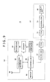
- FIG. 9 is a diagram showing one example of the block configuration of the cellular phone 10.
- the cellular phone 10 includes an antenna 80 and a transmitter/receiver 82 for bidirectional communication with a base station, a speaker 86 for outputting audio such as a ring tone and received speech, and a microphone 84 for collecting transmission speech and so on. Furthermore, the cellular phone 10 includes a controller 88 having a CPU for controlling the whole of the cellular phone 10, a memory 90 formed of a ROM (Read Only Memory) and a RAM (Random Access Memory), and the operation component 92, with which a user carries out input operation. These units are provided inside the first case 50.
- the cellular phone 10 includes a serializer 22 and the TOSA 20 provided in the first case 50, and the ROSA 30, a deserializer 34, and the display unit 40 provided in the second case 52.
- the serializer 22 serializes e.g. an image signal and a video signal supplied via a large number of signal lines connected to the controller 88 and supplies the resulting signals to the TOSA 20.
- the TOSA 20 converts the serialized image signal and so on supplied from the serializer 22 from the electric signal into an optical signal, and transmits the optical signal to the ROSA 30 in the second case 52.
- the ROSA 30 receives the optical signal supplied from the TOSA 20 and converts the optical signal into an electric signal.
- the ROSA 30 supplies the electric signal to the deserializer 34.
- the deserializer 34 parallelizes the serialized electric signal to thereby convert this signal into the original image signal, and supplies it to the display unit 40.
- the display unit 40 displays an image based on the image signal and so on supplied from the deserializer 34 on the screen. In this manner, an image signal, a video signal, and an audio signal can be transmitted between the first case 50 and the second case 52 by optical space transmission (optical wireless communication).
- the display unit 40 is provided only in the second case 52 in the present example, another display unit may be provided in the first case 50. Furthermore, an imaging unit formed of a complementary metal oxide semiconductor (CMOS) and so on may be provided, and a tuner unit may be provided so that the display unit 40 can display a moving image.
- CMOS complementary metal oxide semiconductor
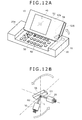
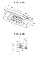
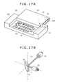
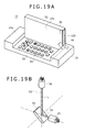
- FIGS. 10A to 20B are diagrams showing the operation of the cellular phone 10 at the time of the optical space transmission.
- Each diagram of FIGS. 10A , 11A , 12A , 13A , 14A , 15A , 16A , 17A , 18A , 19A and 20A shows the operation of the whole of the cellular phone 10, and each diagram of FIGS. 10B , 11B , 12B , 13B , 14B , 15B , 16B , 17B , 18B , 19B and 20B shows only the operation of the mirror 56 and the ROSA 30.
- the second case 52 is rotated about the optical axis O1 by the hinge unit 54. Specifically, the second case 52 is so rotated counterclockwise that the side part 52a of the second case 52 serves as the support point. In linkage with the rotation of the second case 52, the mirror 56 and the ROSA 30 integrally rotate about the optical axis O1. Therefore, the ROSA 30 is so rotated as to be positioned on the optical axis 02. Subsequently, as shown in FIGS. 13A to 15B , the second case 52 is continuously rotated anticlockwise by 180° by the hinge unit 54, so that the second case 52 is turned upside down.
- the second case 52 is slid along the shorter side direction of the first case 50 (arrowhead direction D1).
- the ROSA 30 moves in the arrowhead direction D1 along the optical axis 02 in linkage with the sliding of the second case 52. That is, the ROSA 30 moves in such a direction as to become remoter from the mirror 56.
- the mirror 56 is not slid but at rest because it is fixed to the first case 50 via the hinge unit 54.
- the second case 52 is rotated about the optical axis O1 by the hinge unit 54. Specifically, the second case 52 is so rotated anticlockwise that the side part 52b of the second case 52 serves as the support point. In linkage with the rotation of the second case 52, the mirror 56 and the ROSA 30 integrally rotate about the optical axis O1. Therefore, the ROSA 30 is so rotated as to be positioned on the optical axis 02.
- the second case 52 is continuously rotated anticlockwise by 180° by the hinge unit 54, so that the second case 52 is turned upside down.
- the second case 52 is rotated by 360° totally to revert to its original state through the inversion of the upper and lower faces thereof, which results in the state in which the display unit 40 is disposed at the upper surface of the second case 52 (see FIG. 5 ).
- the state is kept in which the mirror 56 is disposed on the optical axis 01 of the TOSA 20 and the ROSA 30 is disposed on the optical axis 02 of the laser light L bent by the mirror 56 even during the operation of sliding and rotation of the second case 52.
- data transmission by optical space transmission can be carried out between the TOSA 20 and the ROSA 30 even during the operation of the second case 52.
- serializer 22 because data via plural signal lines are serialized by the serializer 22 so that the data can be transmitted by one channel, space saving of the transmission path can be achieved. Although data are thus serialized, the transmission speed is not lowered compared with the wire connection in the related art because data transmission can be carried out by optical space transmission.
- optical space transmission may be achieved by using two or more mirrors and bending the laser light L at two or more positions.
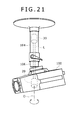
- FIG. 21 is a diagram showing the configuration of a monitoring device 100 according to a second embodiment of the present invention.
- the monitoring device 100 is attached to a ceiling plane in an indoor space or the like via an attachment 104 and used to image and record a specific photographic range in a store, an outdoor space, or the like.
- a rotational hinge unit 106 is interposed between the monitoring device 100 and the attachment 104.
- the rotational hinge unit 106 is rotationally driven by a drive unit (not shown) such as a motor, to thereby rotate the monitoring device 100 about an optical axis O.
- a TOSA 20 is provided inside the monitoring device 100 and a ROSA 30 is provided inside the attachment 104.
- the ROSA 30 is disposed on the optical axis O of the laser light L emitted from the TOSA 20.
- Image data arising from imaging by an imaging unit (not shown) in the monitoring device 100 is supplied to the TOSA 20 via a serializer and so on.
- the TOSA 20 converts the image signal into an optical signal and transmits it to the ROSA 30.
- the ROSA 30 converts the optical signal received from the TOSA 20 into an electric signal and supplies it to a display device and a high-capacity storage such as a hard disk drive (HDD) provided at a predetermined position in the indoor space.
- HDD hard disk drive
- the embodiment can be applied also to the case of expanding and contracting the attachment 104.
- the linear movement of basic operation (1) described for the first embodiment can be employed.
- the ROSA 30 may be disposed on the backside of a ceiling.
- the above-described bending operation of basic operation (3) (see FIG. 4 ) can be employed.
- the monitoring device 100 and the attachment 104 are connected to each other not by a wire line such as a cable but by optical wireless communication. This allows the monitoring device 100 to be infinitely rotated in the range of 360°. Thus, all directions in the indoor space can be easily imaged, which can enhance the safety.
- the embodiments of the present invention can be applied also to personal computers, digital cameras, video cameras, game machines, scanners, and so on having a hinge unit and a slider unit.
Landscapes
- Engineering & Computer Science (AREA)
- Signal Processing (AREA)
- Physics & Mathematics (AREA)
- Electromagnetism (AREA)
- Computer Networks & Wireless Communication (AREA)
- Telephone Set Structure (AREA)
- Optical Couplings Of Light Guides (AREA)
- Optical Communication System (AREA)
Applications Claiming Priority (1)
| Application Number | Priority Date | Filing Date | Title |
|---|---|---|---|
| JP2008128752A JP4596039B2 (ja) | 2008-05-15 | 2008-05-15 | 電子機器 |
Publications (3)
| Publication Number | Publication Date |
|---|---|
| EP2120429A2 true EP2120429A2 (fr) | 2009-11-18 |
| EP2120429A3 EP2120429A3 (fr) | 2010-05-05 |
| EP2120429B1 EP2120429B1 (fr) | 2012-03-28 |
Family
ID=40886749
Family Applications (1)
| Application Number | Title | Priority Date | Filing Date |
|---|---|---|---|
| EP09160205A Not-in-force EP2120429B1 (fr) | 2008-05-15 | 2009-05-14 | Appareil électronique |
Country Status (5)
| Country | Link |
|---|---|
| US (1) | US8335436B2 (fr) |
| EP (1) | EP2120429B1 (fr) |
| JP (1) | JP4596039B2 (fr) |
| CN (2) | CN101582934A (fr) |
| AT (1) | ATE551821T1 (fr) |
Cited By (1)
| Publication number | Priority date | Publication date | Assignee | Title |
|---|---|---|---|---|
| RU2494544C1 (ru) * | 2012-02-24 | 2013-09-27 | Федеральное государственное бюджетное образовательное учреждение высшего профессионального образования "Московский государственный университет приборостроения и информатики" | Устройство передачи информации |
Families Citing this family (4)
| Publication number | Priority date | Publication date | Assignee | Title |
|---|---|---|---|---|
| JP5696584B2 (ja) * | 2011-05-20 | 2015-04-08 | ヤマハ株式会社 | 中継装置及びスピーカ装置 |
| JP5831404B2 (ja) * | 2012-08-30 | 2015-12-09 | ヤマハ株式会社 | 中継装置およびスピーカ装置 |
| FR3047094B1 (fr) * | 2016-01-26 | 2019-11-22 | Raoul Parienti | Assistant numerique personnel emboitant un ordiphone, clavier et tablette capable de prendre des prises de vues 3d |
| DE112018001820T5 (de) * | 2017-05-01 | 2019-12-19 | Eaton Intelligent Power Limited | Drahtloser überwachungs- und konfigurations-tether zur verwendung mit einem isolierten industrieprodukt und verfahren zu dessen betrieb |
Citations (4)
| Publication number | Priority date | Publication date | Assignee | Title |
|---|---|---|---|---|
| JP2005333019A (ja) | 2004-05-20 | 2005-12-02 | Sony Corp | 光コネクタおよび光通信装置 |
| JP2006303719A (ja) | 2005-04-18 | 2006-11-02 | Sony Ericsson Mobilecommunications Japan Inc | 携帯無線機 |
| JP2007534242A (ja) | 2004-04-22 | 2007-11-22 | ソニー エリクソン モバイル コミュニケーションズ, エービー | 変形可能な通信装置 |
| JP2008128752A (ja) | 2006-11-20 | 2008-06-05 | Tokyo Cosmos Electric Co Ltd | 非接触型角度センサ |
Family Cites Families (23)
| Publication number | Priority date | Publication date | Assignee | Title |
|---|---|---|---|---|
| JP3519554B2 (ja) * | 1996-09-20 | 2004-04-19 | 株式会社東芝 | 携帯型電子機器 |
| US5889602A (en) * | 1996-12-10 | 1999-03-30 | Motorola, Inc. | Optical hinge |
| JPH10301679A (ja) * | 1997-04-22 | 1998-11-13 | Toshiba Corp | 光通信機能を有する携帯形情報機器 |
| JP2000194459A (ja) * | 1998-12-28 | 2000-07-14 | Seiko Epson Corp | 光デ―タ伝送機構および電子機器 |
| US6470132B1 (en) * | 2000-09-05 | 2002-10-22 | Nokia Mobile Phones Ltd. | Optical hinge apparatus |
| JP2002157046A (ja) * | 2000-11-21 | 2002-05-31 | Nec Yonezawa Ltd | 可動部の信号伝達機構 |
| JP2003174495A (ja) * | 2001-09-28 | 2003-06-20 | Nec Corp | 折り畳み式携帯情報端末 |
| JP2003298698A (ja) * | 2002-03-29 | 2003-10-17 | Nec Corp | 折り畳み式携帯情報端末 |
| JP2003348203A (ja) * | 2002-05-27 | 2003-12-05 | Matsushita Electric Ind Co Ltd | ユニット間通信装置及びこれを備えた携帯電子機器 |
| GB2406987A (en) * | 2003-10-06 | 2005-04-13 | Nokia Corp | Dual channel optical communication link |
| JPWO2006030607A1 (ja) * | 2004-09-14 | 2008-05-08 | 三菱電機株式会社 | 携帯機器 |
| TWI253895B (en) * | 2005-01-28 | 2006-04-21 | Benq Corp | Sliding and rotation complex mechanism of a handheld communication device |
| US20070032275A1 (en) * | 2005-07-25 | 2007-02-08 | Adamant Kogyo Co., Ltd. | Internal optical fiber hinge system for a consumer electronic device |
| JP4567563B2 (ja) * | 2005-09-22 | 2010-10-20 | 富士通株式会社 | 携帯端末装置、ヒンジ装置、筒状部材及び光通信システム |
| JP4205105B2 (ja) * | 2006-01-04 | 2009-01-07 | 株式会社東芝 | 携帯電子機器 |
| JP2007274057A (ja) * | 2006-03-30 | 2007-10-18 | Nec Corp | 携帯無線端末 |
| JP2007328598A (ja) * | 2006-06-08 | 2007-12-20 | Fuji Xerox Co Ltd | 電子装置 |
| US8267598B2 (en) * | 2006-12-06 | 2012-09-18 | Motorola Mobility Llc | Point to point optical communication system for conveying signals between multiple housings of a device |
| US7672594B2 (en) * | 2006-12-06 | 2010-03-02 | Motorola, Inc. | Optical communication system with light guide having variable slidable point of entry or exit |
| US7338193B1 (en) * | 2007-01-11 | 2008-03-04 | Motorola, Inc. | Light transfer device for an electronic device |
| US7873279B2 (en) * | 2007-01-11 | 2011-01-18 | Motorola Mobility, Inc. | Light transfer apparatus for an electronic device |
| US7480427B2 (en) * | 2007-06-12 | 2009-01-20 | Motorola, Inc. | Electronic device and arrangement for providing communication between body parts thereof |
| US8224137B2 (en) * | 2007-10-11 | 2012-07-17 | Motorola Mobility, Inc. | Apparatus with two housings including a rotatable optical data communication coupling |
-
2008
- 2008-05-15 JP JP2008128752A patent/JP4596039B2/ja not_active Expired - Fee Related
-
2009
- 2009-04-29 US US12/432,472 patent/US8335436B2/en not_active Expired - Fee Related
- 2009-05-14 EP EP09160205A patent/EP2120429B1/fr not_active Not-in-force
- 2009-05-14 AT AT09160205T patent/ATE551821T1/de active
- 2009-05-15 CN CNA2009101407921A patent/CN101582934A/zh active Pending
- 2009-05-15 CN CN201310706461.6A patent/CN103763410A/zh active Pending
Patent Citations (4)
| Publication number | Priority date | Publication date | Assignee | Title |
|---|---|---|---|---|
| JP2007534242A (ja) | 2004-04-22 | 2007-11-22 | ソニー エリクソン モバイル コミュニケーションズ, エービー | 変形可能な通信装置 |
| JP2005333019A (ja) | 2004-05-20 | 2005-12-02 | Sony Corp | 光コネクタおよび光通信装置 |
| JP2006303719A (ja) | 2005-04-18 | 2006-11-02 | Sony Ericsson Mobilecommunications Japan Inc | 携帯無線機 |
| JP2008128752A (ja) | 2006-11-20 | 2008-06-05 | Tokyo Cosmos Electric Co Ltd | 非接触型角度センサ |
Cited By (1)
| Publication number | Priority date | Publication date | Assignee | Title |
|---|---|---|---|---|
| RU2494544C1 (ru) * | 2012-02-24 | 2013-09-27 | Федеральное государственное бюджетное образовательное учреждение высшего профессионального образования "Московский государственный университет приборостроения и информатики" | Устройство передачи информации |
Also Published As
| Publication number | Publication date |
|---|---|
| CN103763410A (zh) | 2014-04-30 |
| US8335436B2 (en) | 2012-12-18 |
| EP2120429B1 (fr) | 2012-03-28 |
| EP2120429A3 (fr) | 2010-05-05 |
| CN101582934A (zh) | 2009-11-18 |
| JP2009278463A (ja) | 2009-11-26 |
| ATE551821T1 (de) | 2012-04-15 |
| US20090285578A1 (en) | 2009-11-19 |
| JP4596039B2 (ja) | 2010-12-08 |
Similar Documents
| Publication | Publication Date | Title |
|---|---|---|
| US11140249B2 (en) | Transmission module, transmission mechanism, and mobile terminal | |
| EP2120429B1 (fr) | Appareil électronique | |
| CN109274877B (zh) | 成像模组、摄像头组件及电子装置 | |
| JP4454677B2 (ja) | 携帯端末 | |
| CN109327572B (zh) | 成像模组、摄像头组件及电子装置 | |
| US7778503B2 (en) | Electronic device having optical data connection of movable housing parts | |
| US7755859B2 (en) | Lens assembly of camera module | |
| US20070153457A1 (en) | Portable electronic device | |
| US20080253070A1 (en) | Foldable electronic device having optical data connection of housing parts | |
| WO2020108058A1 (fr) | Terminal mobile | |
| CN109327571B (zh) | 摄像头组件及电子装置 | |
| EP2128672A1 (fr) | Guide d'ondes optiques, module de guide d'ondes optiques et appareil électronique | |
| KR101082730B1 (ko) | 광전송 모듈, 전자 기기, 광전송 모듈의 조립 방법 및 광전송 방법 | |
| US20100265349A1 (en) | Digital camera module | |
| JP2005252334A (ja) | 光伝送モジュールおよびこれを用いた携帯情報機器 | |
| KR20110024463A (ko) | 렌즈 구동 모듈 | |
| JP5092386B2 (ja) | 光電変換モジュール、レセプタ、および、電子機器 | |
| CN109167908B (zh) | 成像模组、摄像头组件及电子装置 | |
| KR20060091682A (ko) | 양방향 슬라이딩 휴대전화 | |
| CN209560150U (zh) | 光学收发组件及光纤缆线模块 | |
| JP4659596B2 (ja) | 通信装置 | |
| KR20140075187A (ko) | 전자기기의 외부기기와의 인터페이싱을 위한 마이크로폼 팩터 광전모듈 | |
| WO2011007471A1 (fr) | Dispositif de rotation et terminal mobile ouvrant équipé de celui-ci | |
| JP2014057242A (ja) | ファインダ装置、並びにこれを搭載するデジタルカメラ及び携帯端末装置 | |
| KR20230000359A (ko) | 회로기판, 카메라 모듈 및 이를 포함하는 광학기기 |
Legal Events
| Date | Code | Title | Description |
|---|---|---|---|
| PUAI | Public reference made under article 153(3) epc to a published international application that has entered the european phase |
Free format text: ORIGINAL CODE: 0009012 |
|
| 17P | Request for examination filed |
Effective date: 20090514 |
|
| AK | Designated contracting states |
Kind code of ref document: A2 Designated state(s): AT BE BG CH CY CZ DE DK EE ES FI FR GB GR HR HU IE IS IT LI LT LU LV MC MK MT NL NO PL PT RO SE SI SK TR |
|
| PUAL | Search report despatched |
Free format text: ORIGINAL CODE: 0009013 |
|
| AK | Designated contracting states |
Kind code of ref document: A3 Designated state(s): AT BE BG CH CY CZ DE DK EE ES FI FR GB GR HR HU IE IS IT LI LT LU LV MC MK MT NL NO PL PT RO SE SI SK TR |
|
| AX | Request for extension of the european patent |
Extension state: AL BA RS |
|
| RIC1 | Information provided on ipc code assigned before grant |
Ipc: H04M 1/02 20060101AFI20090728BHEP Ipc: H04B 10/10 20060101ALI20100330BHEP Ipc: H04B 10/00 20060101ALI20100330BHEP Ipc: G02B 6/36 20060101ALI20100330BHEP |
|
| 17Q | First examination report despatched |
Effective date: 20100519 |
|
| GRAP | Despatch of communication of intention to grant a patent |
Free format text: ORIGINAL CODE: EPIDOSNIGR1 |
|
| RIC1 | Information provided on ipc code assigned before grant |
Ipc: H04M 1/02 20060101AFI20110927BHEP Ipc: G02B 6/36 20060101ALI20110927BHEP Ipc: H04B 10/10 20060101ALI20110927BHEP Ipc: H04B 10/00 20060101ALI20110927BHEP |
|
| GRAS | Grant fee paid |
Free format text: ORIGINAL CODE: EPIDOSNIGR3 |
|
| GRAA | (expected) grant |
Free format text: ORIGINAL CODE: 0009210 |
|
| AK | Designated contracting states |
Kind code of ref document: B1 Designated state(s): AT BE BG CH CY CZ DE DK EE ES FI FR GB GR HR HU IE IS IT LI LT LU LV MC MK MT NL NO PL PT RO SE SI SK TR |
|
| REG | Reference to a national code |
Ref country code: GB Ref legal event code: FG4D |
|
| REG | Reference to a national code |
Ref country code: CH Ref legal event code: EP |
|
| REG | Reference to a national code |
Ref country code: AT Ref legal event code: REF Ref document number: 551821 Country of ref document: AT Kind code of ref document: T Effective date: 20120415 |
|
| REG | Reference to a national code |
Ref country code: IE Ref legal event code: FG4D |
|
| REG | Reference to a national code |
Ref country code: DE Ref legal event code: R096 Ref document number: 602009006084 Country of ref document: DE Effective date: 20120524 |
|
| REG | Reference to a national code |
Ref country code: NL Ref legal event code: VDEP Effective date: 20120328 |
|
| PG25 | Lapsed in a contracting state [announced via postgrant information from national office to epo] |
Ref country code: HR Free format text: LAPSE BECAUSE OF FAILURE TO SUBMIT A TRANSLATION OF THE DESCRIPTION OR TO PAY THE FEE WITHIN THE PRESCRIBED TIME-LIMIT Effective date: 20120328 Ref country code: NO Free format text: LAPSE BECAUSE OF FAILURE TO SUBMIT A TRANSLATION OF THE DESCRIPTION OR TO PAY THE FEE WITHIN THE PRESCRIBED TIME-LIMIT Effective date: 20120628 Ref country code: LT Free format text: LAPSE BECAUSE OF FAILURE TO SUBMIT A TRANSLATION OF THE DESCRIPTION OR TO PAY THE FEE WITHIN THE PRESCRIBED TIME-LIMIT Effective date: 20120328 |
|
| LTIE | Lt: invalidation of european patent or patent extension |
Effective date: 20120328 |
|
| PG25 | Lapsed in a contracting state [announced via postgrant information from national office to epo] |
Ref country code: GR Free format text: LAPSE BECAUSE OF FAILURE TO SUBMIT A TRANSLATION OF THE DESCRIPTION OR TO PAY THE FEE WITHIN THE PRESCRIBED TIME-LIMIT Effective date: 20120629 Ref country code: LV Free format text: LAPSE BECAUSE OF FAILURE TO SUBMIT A TRANSLATION OF THE DESCRIPTION OR TO PAY THE FEE WITHIN THE PRESCRIBED TIME-LIMIT Effective date: 20120328 Ref country code: FI Free format text: LAPSE BECAUSE OF FAILURE TO SUBMIT A TRANSLATION OF THE DESCRIPTION OR TO PAY THE FEE WITHIN THE PRESCRIBED TIME-LIMIT Effective date: 20120328 |
|
| REG | Reference to a national code |
Ref country code: AT Ref legal event code: MK05 Ref document number: 551821 Country of ref document: AT Kind code of ref document: T Effective date: 20120328 |
|
| PG25 | Lapsed in a contracting state [announced via postgrant information from national office to epo] |
Ref country code: CY Free format text: LAPSE BECAUSE OF FAILURE TO SUBMIT A TRANSLATION OF THE DESCRIPTION OR TO PAY THE FEE WITHIN THE PRESCRIBED TIME-LIMIT Effective date: 20120328 |
|
| PG25 | Lapsed in a contracting state [announced via postgrant information from national office to epo] |
Ref country code: RO Free format text: LAPSE BECAUSE OF FAILURE TO SUBMIT A TRANSLATION OF THE DESCRIPTION OR TO PAY THE FEE WITHIN THE PRESCRIBED TIME-LIMIT Effective date: 20120328 Ref country code: CZ Free format text: LAPSE BECAUSE OF FAILURE TO SUBMIT A TRANSLATION OF THE DESCRIPTION OR TO PAY THE FEE WITHIN THE PRESCRIBED TIME-LIMIT Effective date: 20120328 Ref country code: EE Free format text: LAPSE BECAUSE OF FAILURE TO SUBMIT A TRANSLATION OF THE DESCRIPTION OR TO PAY THE FEE WITHIN THE PRESCRIBED TIME-LIMIT Effective date: 20120328 Ref country code: IS Free format text: LAPSE BECAUSE OF FAILURE TO SUBMIT A TRANSLATION OF THE DESCRIPTION OR TO PAY THE FEE WITHIN THE PRESCRIBED TIME-LIMIT Effective date: 20120728 Ref country code: SE Free format text: LAPSE BECAUSE OF FAILURE TO SUBMIT A TRANSLATION OF THE DESCRIPTION OR TO PAY THE FEE WITHIN THE PRESCRIBED TIME-LIMIT Effective date: 20120328 Ref country code: PL Free format text: LAPSE BECAUSE OF FAILURE TO SUBMIT A TRANSLATION OF THE DESCRIPTION OR TO PAY THE FEE WITHIN THE PRESCRIBED TIME-LIMIT Effective date: 20120328 Ref country code: BE Free format text: LAPSE BECAUSE OF FAILURE TO SUBMIT A TRANSLATION OF THE DESCRIPTION OR TO PAY THE FEE WITHIN THE PRESCRIBED TIME-LIMIT Effective date: 20120328 Ref country code: SI Free format text: LAPSE BECAUSE OF FAILURE TO SUBMIT A TRANSLATION OF THE DESCRIPTION OR TO PAY THE FEE WITHIN THE PRESCRIBED TIME-LIMIT Effective date: 20120328 |
|
| PG25 | Lapsed in a contracting state [announced via postgrant information from national office to epo] |
Ref country code: PT Free format text: LAPSE BECAUSE OF FAILURE TO SUBMIT A TRANSLATION OF THE DESCRIPTION OR TO PAY THE FEE WITHIN THE PRESCRIBED TIME-LIMIT Effective date: 20120730 Ref country code: SK Free format text: LAPSE BECAUSE OF FAILURE TO SUBMIT A TRANSLATION OF THE DESCRIPTION OR TO PAY THE FEE WITHIN THE PRESCRIBED TIME-LIMIT Effective date: 20120328 |
|
| PG25 | Lapsed in a contracting state [announced via postgrant information from national office to epo] |
Ref country code: MC Free format text: LAPSE BECAUSE OF NON-PAYMENT OF DUE FEES Effective date: 20120531 |
|
| PG25 | Lapsed in a contracting state [announced via postgrant information from national office to epo] |
Ref country code: DK Free format text: LAPSE BECAUSE OF FAILURE TO SUBMIT A TRANSLATION OF THE DESCRIPTION OR TO PAY THE FEE WITHIN THE PRESCRIBED TIME-LIMIT Effective date: 20120328 Ref country code: NL Free format text: LAPSE BECAUSE OF FAILURE TO SUBMIT A TRANSLATION OF THE DESCRIPTION OR TO PAY THE FEE WITHIN THE PRESCRIBED TIME-LIMIT Effective date: 20120328 Ref country code: AT Free format text: LAPSE BECAUSE OF FAILURE TO SUBMIT A TRANSLATION OF THE DESCRIPTION OR TO PAY THE FEE WITHIN THE PRESCRIBED TIME-LIMIT Effective date: 20120328 |
|
| PLBE | No opposition filed within time limit |
Free format text: ORIGINAL CODE: 0009261 |
|
| STAA | Information on the status of an ep patent application or granted ep patent |
Free format text: STATUS: NO OPPOSITION FILED WITHIN TIME LIMIT |
|
| REG | Reference to a national code |
Ref country code: IE Ref legal event code: MM4A |
|
| PG25 | Lapsed in a contracting state [announced via postgrant information from national office to epo] |
Ref country code: MK Free format text: LAPSE BECAUSE OF FAILURE TO SUBMIT A TRANSLATION OF THE DESCRIPTION OR TO PAY THE FEE WITHIN THE PRESCRIBED TIME-LIMIT Effective date: 20120328 Ref country code: IT Free format text: LAPSE BECAUSE OF FAILURE TO SUBMIT A TRANSLATION OF THE DESCRIPTION OR TO PAY THE FEE WITHIN THE PRESCRIBED TIME-LIMIT Effective date: 20120328 |
|
| 26N | No opposition filed |
Effective date: 20130103 |
|
| REG | Reference to a national code |
Ref country code: DE Ref legal event code: R097 Ref document number: 602009006084 Country of ref document: DE Effective date: 20130103 |
|
| PG25 | Lapsed in a contracting state [announced via postgrant information from national office to epo] |
Ref country code: ES Free format text: LAPSE BECAUSE OF FAILURE TO SUBMIT A TRANSLATION OF THE DESCRIPTION OR TO PAY THE FEE WITHIN THE PRESCRIBED TIME-LIMIT Effective date: 20120709 Ref country code: IE Free format text: LAPSE BECAUSE OF NON-PAYMENT OF DUE FEES Effective date: 20120514 |
|
| PG25 | Lapsed in a contracting state [announced via postgrant information from national office to epo] |
Ref country code: BG Free format text: LAPSE BECAUSE OF FAILURE TO SUBMIT A TRANSLATION OF THE DESCRIPTION OR TO PAY THE FEE WITHIN THE PRESCRIBED TIME-LIMIT Effective date: 20120628 Ref country code: MT Free format text: LAPSE BECAUSE OF FAILURE TO SUBMIT A TRANSLATION OF THE DESCRIPTION OR TO PAY THE FEE WITHIN THE PRESCRIBED TIME-LIMIT Effective date: 20120328 |
|
| REG | Reference to a national code |
Ref country code: CH Ref legal event code: PL |
|
| PG25 | Lapsed in a contracting state [announced via postgrant information from national office to epo] |
Ref country code: LI Free format text: LAPSE BECAUSE OF NON-PAYMENT OF DUE FEES Effective date: 20130531 Ref country code: CH Free format text: LAPSE BECAUSE OF NON-PAYMENT OF DUE FEES Effective date: 20130531 |
|
| PG25 | Lapsed in a contracting state [announced via postgrant information from national office to epo] |
Ref country code: TR Free format text: LAPSE BECAUSE OF FAILURE TO SUBMIT A TRANSLATION OF THE DESCRIPTION OR TO PAY THE FEE WITHIN THE PRESCRIBED TIME-LIMIT Effective date: 20120328 |
|
| PG25 | Lapsed in a contracting state [announced via postgrant information from national office to epo] |
Ref country code: LU Free format text: LAPSE BECAUSE OF NON-PAYMENT OF DUE FEES Effective date: 20120514 |
|
| PG25 | Lapsed in a contracting state [announced via postgrant information from national office to epo] |
Ref country code: HU Free format text: LAPSE BECAUSE OF FAILURE TO SUBMIT A TRANSLATION OF THE DESCRIPTION OR TO PAY THE FEE WITHIN THE PRESCRIBED TIME-LIMIT Effective date: 20090514 |
|
| PGFP | Annual fee paid to national office [announced via postgrant information from national office to epo] |
Ref country code: GB Payment date: 20140521 Year of fee payment: 6 |
|
| PGFP | Annual fee paid to national office [announced via postgrant information from national office to epo] |
Ref country code: FR Payment date: 20140527 Year of fee payment: 6 Ref country code: DE Payment date: 20140521 Year of fee payment: 6 |
|
| REG | Reference to a national code |
Ref country code: DE Ref legal event code: R119 Ref document number: 602009006084 Country of ref document: DE |
|
| GBPC | Gb: european patent ceased through non-payment of renewal fee |
Effective date: 20150514 |
|
| REG | Reference to a national code |
Ref country code: FR Ref legal event code: ST Effective date: 20160129 |
|
| PG25 | Lapsed in a contracting state [announced via postgrant information from national office to epo] |
Ref country code: GB Free format text: LAPSE BECAUSE OF NON-PAYMENT OF DUE FEES Effective date: 20150514 Ref country code: DE Free format text: LAPSE BECAUSE OF NON-PAYMENT OF DUE FEES Effective date: 20151201 |
|
| PG25 | Lapsed in a contracting state [announced via postgrant information from national office to epo] |
Ref country code: FR Free format text: LAPSE BECAUSE OF NON-PAYMENT OF DUE FEES Effective date: 20150601 |