EP2118911B1 - Tissus thermofusibles pouvant être chauffés intrinsèquement - Google Patents
Tissus thermofusibles pouvant être chauffés intrinsèquement Download PDFInfo
- Publication number
- EP2118911B1 EP2118911B1 EP08708559.3A EP08708559A EP2118911B1 EP 2118911 B1 EP2118911 B1 EP 2118911B1 EP 08708559 A EP08708559 A EP 08708559A EP 2118911 B1 EP2118911 B1 EP 2118911B1
- Authority
- EP
- European Patent Office
- Prior art keywords
- planar structure
- adhesive
- structure according
- hotmelt
- layer
- Prior art date
- Legal status (The legal status is an assumption and is not a legal conclusion. Google has not performed a legal analysis and makes no representation as to the accuracy of the status listed.)
- Active
Links
Images


Classifications
-
- H—ELECTRICITY
- H01—ELECTRIC ELEMENTS
- H01C—RESISTORS
- H01C7/00—Non-adjustable resistors formed as one or more layers or coatings; Non-adjustable resistors made from powdered conducting material or powdered semi-conducting material with or without insulating material
- H01C7/02—Non-adjustable resistors formed as one or more layers or coatings; Non-adjustable resistors made from powdered conducting material or powdered semi-conducting material with or without insulating material having positive temperature coefficient
- H01C7/027—Non-adjustable resistors formed as one or more layers or coatings; Non-adjustable resistors made from powdered conducting material or powdered semi-conducting material with or without insulating material having positive temperature coefficient consisting of conducting or semi-conducting material dispersed in a non-conductive organic material
-
- C—CHEMISTRY; METALLURGY
- C09—DYES; PAINTS; POLISHES; NATURAL RESINS; ADHESIVES; COMPOSITIONS NOT OTHERWISE PROVIDED FOR; APPLICATIONS OF MATERIALS NOT OTHERWISE PROVIDED FOR
- C09J—ADHESIVES; NON-MECHANICAL ASPECTS OF ADHESIVE PROCESSES IN GENERAL; ADHESIVE PROCESSES NOT PROVIDED FOR ELSEWHERE; USE OF MATERIALS AS ADHESIVES
- C09J133/00—Adhesives based on homopolymers or copolymers of compounds having one or more unsaturated aliphatic radicals, each having only one carbon-to-carbon double bond, and at least one being terminated by only one carboxyl radical, or of salts, anhydrides, esters, amides, imides, or nitriles thereof; Adhesives based on derivatives of such polymers
- C09J133/04—Homopolymers or copolymers of esters
- C09J133/06—Homopolymers or copolymers of esters of esters containing only carbon, hydrogen and oxygen, the oxygen atom being present only as part of the carboxyl radical
-
- C—CHEMISTRY; METALLURGY
- C09—DYES; PAINTS; POLISHES; NATURAL RESINS; ADHESIVES; COMPOSITIONS NOT OTHERWISE PROVIDED FOR; APPLICATIONS OF MATERIALS NOT OTHERWISE PROVIDED FOR
- C09J—ADHESIVES; NON-MECHANICAL ASPECTS OF ADHESIVE PROCESSES IN GENERAL; ADHESIVE PROCESSES NOT PROVIDED FOR ELSEWHERE; USE OF MATERIALS AS ADHESIVES
- C09J7/00—Adhesives in the form of films or foils
- C09J7/20—Adhesives in the form of films or foils characterised by their carriers
- C09J7/22—Plastics; Metallised plastics
-
- C—CHEMISTRY; METALLURGY
- C09—DYES; PAINTS; POLISHES; NATURAL RESINS; ADHESIVES; COMPOSITIONS NOT OTHERWISE PROVIDED FOR; APPLICATIONS OF MATERIALS NOT OTHERWISE PROVIDED FOR
- C09J—ADHESIVES; NON-MECHANICAL ASPECTS OF ADHESIVE PROCESSES IN GENERAL; ADHESIVE PROCESSES NOT PROVIDED FOR ELSEWHERE; USE OF MATERIALS AS ADHESIVES
- C09J7/00—Adhesives in the form of films or foils
- C09J7/20—Adhesives in the form of films or foils characterised by their carriers
- C09J7/28—Metal sheet
-
- C—CHEMISTRY; METALLURGY
- C09—DYES; PAINTS; POLISHES; NATURAL RESINS; ADHESIVES; COMPOSITIONS NOT OTHERWISE PROVIDED FOR; APPLICATIONS OF MATERIALS NOT OTHERWISE PROVIDED FOR
- C09J—ADHESIVES; NON-MECHANICAL ASPECTS OF ADHESIVE PROCESSES IN GENERAL; ADHESIVE PROCESSES NOT PROVIDED FOR ELSEWHERE; USE OF MATERIALS AS ADHESIVES
- C09J7/00—Adhesives in the form of films or foils
- C09J7/30—Adhesives in the form of films or foils characterised by the adhesive composition
- C09J7/35—Heat-activated
-
- C—CHEMISTRY; METALLURGY
- C09—DYES; PAINTS; POLISHES; NATURAL RESINS; ADHESIVES; COMPOSITIONS NOT OTHERWISE PROVIDED FOR; APPLICATIONS OF MATERIALS NOT OTHERWISE PROVIDED FOR
- C09J—ADHESIVES; NON-MECHANICAL ASPECTS OF ADHESIVE PROCESSES IN GENERAL; ADHESIVE PROCESSES NOT PROVIDED FOR ELSEWHERE; USE OF MATERIALS AS ADHESIVES
- C09J9/00—Adhesives characterised by their physical nature or the effects produced, e.g. glue sticks
- C09J9/02—Electrically-conducting adhesives
-
- H—ELECTRICITY
- H05—ELECTRIC TECHNIQUES NOT OTHERWISE PROVIDED FOR
- H05B—ELECTRIC HEATING; ELECTRIC LIGHT SOURCES NOT OTHERWISE PROVIDED FOR; CIRCUIT ARRANGEMENTS FOR ELECTRIC LIGHT SOURCES, IN GENERAL
- H05B3/00—Ohmic-resistance heating
- H05B3/20—Heating elements having extended surface area substantially in a two-dimensional [2D] plane, e.g. plate-heater
- H05B3/34—Heating elements having extended surface area substantially in a two-dimensional [2D] plane, e.g. plate-heater flexible, e.g. heating nets or webs
-
- H—ELECTRICITY
- H05—ELECTRIC TECHNIQUES NOT OTHERWISE PROVIDED FOR
- H05B—ELECTRIC HEATING; ELECTRIC LIGHT SOURCES NOT OTHERWISE PROVIDED FOR; CIRCUIT ARRANGEMENTS FOR ELECTRIC LIGHT SOURCES, IN GENERAL
- H05B3/00—Ohmic-resistance heating
- H05B3/84—Heating arrangements specially adapted for transparent or reflecting areas, e.g. for demisting or de-icing windows, mirrors or vehicle windshields
- H05B3/845—Heating arrangements specially adapted for transparent or reflecting areas, e.g. for demisting or de-icing windows, mirrors or vehicle windshields specially adapted for reflecting surfaces, e.g. bathroom - or rearview mirrors
-
- C—CHEMISTRY; METALLURGY
- C09—DYES; PAINTS; POLISHES; NATURAL RESINS; ADHESIVES; COMPOSITIONS NOT OTHERWISE PROVIDED FOR; APPLICATIONS OF MATERIALS NOT OTHERWISE PROVIDED FOR
- C09J—ADHESIVES; NON-MECHANICAL ASPECTS OF ADHESIVE PROCESSES IN GENERAL; ADHESIVE PROCESSES NOT PROVIDED FOR ELSEWHERE; USE OF MATERIALS AS ADHESIVES
- C09J2301/00—Additional features of adhesives in the form of films or foils
- C09J2301/10—Additional features of adhesives in the form of films or foils characterized by the structural features of the adhesive tape or sheet
- C09J2301/12—Additional features of adhesives in the form of films or foils characterized by the structural features of the adhesive tape or sheet by the arrangement of layers
- C09J2301/124—Additional features of adhesives in the form of films or foils characterized by the structural features of the adhesive tape or sheet by the arrangement of layers the adhesive layer being present on both sides of the carrier, e.g. double-sided adhesive tape
-
- C—CHEMISTRY; METALLURGY
- C09—DYES; PAINTS; POLISHES; NATURAL RESINS; ADHESIVES; COMPOSITIONS NOT OTHERWISE PROVIDED FOR; APPLICATIONS OF MATERIALS NOT OTHERWISE PROVIDED FOR
- C09J—ADHESIVES; NON-MECHANICAL ASPECTS OF ADHESIVE PROCESSES IN GENERAL; ADHESIVE PROCESSES NOT PROVIDED FOR ELSEWHERE; USE OF MATERIALS AS ADHESIVES
- C09J2301/00—Additional features of adhesives in the form of films or foils
- C09J2301/20—Additional features of adhesives in the form of films or foils characterized by the structural features of the adhesive itself
- C09J2301/208—Additional features of adhesives in the form of films or foils characterized by the structural features of the adhesive itself the adhesive layer being constituted by at least two or more adjacent or superposed adhesive layers, e.g. multilayer adhesive
-
- C—CHEMISTRY; METALLURGY
- C09—DYES; PAINTS; POLISHES; NATURAL RESINS; ADHESIVES; COMPOSITIONS NOT OTHERWISE PROVIDED FOR; APPLICATIONS OF MATERIALS NOT OTHERWISE PROVIDED FOR
- C09J—ADHESIVES; NON-MECHANICAL ASPECTS OF ADHESIVE PROCESSES IN GENERAL; ADHESIVE PROCESSES NOT PROVIDED FOR ELSEWHERE; USE OF MATERIALS AS ADHESIVES
- C09J2301/00—Additional features of adhesives in the form of films or foils
- C09J2301/30—Additional features of adhesives in the form of films or foils characterized by the chemical, physicochemical or physical properties of the adhesive or the carrier
- C09J2301/304—Additional features of adhesives in the form of films or foils characterized by the chemical, physicochemical or physical properties of the adhesive or the carrier the adhesive being heat-activatable, i.e. not tacky at temperatures inferior to 30°C
-
- C—CHEMISTRY; METALLURGY
- C09—DYES; PAINTS; POLISHES; NATURAL RESINS; ADHESIVES; COMPOSITIONS NOT OTHERWISE PROVIDED FOR; APPLICATIONS OF MATERIALS NOT OTHERWISE PROVIDED FOR
- C09J—ADHESIVES; NON-MECHANICAL ASPECTS OF ADHESIVE PROCESSES IN GENERAL; ADHESIVE PROCESSES NOT PROVIDED FOR ELSEWHERE; USE OF MATERIALS AS ADHESIVES
- C09J2301/00—Additional features of adhesives in the form of films or foils
- C09J2301/30—Additional features of adhesives in the form of films or foils characterized by the chemical, physicochemical or physical properties of the adhesive or the carrier
- C09J2301/314—Additional features of adhesives in the form of films or foils characterized by the chemical, physicochemical or physical properties of the adhesive or the carrier the adhesive layer and/or the carrier being conductive
-
- H—ELECTRICITY
- H05—ELECTRIC TECHNIQUES NOT OTHERWISE PROVIDED FOR
- H05B—ELECTRIC HEATING; ELECTRIC LIGHT SOURCES NOT OTHERWISE PROVIDED FOR; CIRCUIT ARRANGEMENTS FOR ELECTRIC LIGHT SOURCES, IN GENERAL
- H05B2203/00—Aspects relating to Ohmic resistive heating covered by group H05B3/00
- H05B2203/002—Heaters using a particular layout for the resistive material or resistive elements
- H05B2203/006—Heaters using a particular layout for the resistive material or resistive elements using interdigitated electrodes
-
- H—ELECTRICITY
- H05—ELECTRIC TECHNIQUES NOT OTHERWISE PROVIDED FOR
- H05B—ELECTRIC HEATING; ELECTRIC LIGHT SOURCES NOT OTHERWISE PROVIDED FOR; CIRCUIT ARRANGEMENTS FOR ELECTRIC LIGHT SOURCES, IN GENERAL
- H05B2203/00—Aspects relating to Ohmic resistive heating covered by group H05B3/00
- H05B2203/009—Heaters using conductive material in contact with opposing surfaces of the resistive element or resistive layer
-
- H—ELECTRICITY
- H05—ELECTRIC TECHNIQUES NOT OTHERWISE PROVIDED FOR
- H05B—ELECTRIC HEATING; ELECTRIC LIGHT SOURCES NOT OTHERWISE PROVIDED FOR; CIRCUIT ARRANGEMENTS FOR ELECTRIC LIGHT SOURCES, IN GENERAL
- H05B2203/00—Aspects relating to Ohmic resistive heating covered by group H05B3/00
- H05B2203/02—Heaters using heating elements having a positive temperature coefficient
-
- Y—GENERAL TAGGING OF NEW TECHNOLOGICAL DEVELOPMENTS; GENERAL TAGGING OF CROSS-SECTIONAL TECHNOLOGIES SPANNING OVER SEVERAL SECTIONS OF THE IPC; TECHNICAL SUBJECTS COVERED BY FORMER USPC CROSS-REFERENCE ART COLLECTIONS [XRACs] AND DIGESTS
- Y10—TECHNICAL SUBJECTS COVERED BY FORMER USPC
- Y10T—TECHNICAL SUBJECTS COVERED BY FORMER US CLASSIFICATION
- Y10T428/00—Stock material or miscellaneous articles
- Y10T428/26—Web or sheet containing structurally defined element or component, the element or component having a specified physical dimension
-
- Y—GENERAL TAGGING OF NEW TECHNOLOGICAL DEVELOPMENTS; GENERAL TAGGING OF CROSS-SECTIONAL TECHNOLOGIES SPANNING OVER SEVERAL SECTIONS OF THE IPC; TECHNICAL SUBJECTS COVERED BY FORMER USPC CROSS-REFERENCE ART COLLECTIONS [XRACs] AND DIGESTS
- Y10—TECHNICAL SUBJECTS COVERED BY FORMER USPC
- Y10T—TECHNICAL SUBJECTS COVERED BY FORMER US CLASSIFICATION
- Y10T428/00—Stock material or miscellaneous articles
- Y10T428/28—Web or sheet containing structurally defined element or component and having an adhesive outermost layer
- Y10T428/2813—Heat or solvent activated or sealable
- Y10T428/2817—Heat sealable
- Y10T428/2826—Synthetic resin or polymer
Definitions
- the invention relates to fabrics consisting of at least one layer of hot-melt adhesive and the use thereof.
- the PTC effect is exhibited by current-conducting materials that can conduct electricity better at lower temperatures than at high ones. Such materials are also called PTC thermistors; the materials behave accordingly cold conducting.
- PTC elements contacted with aluminum conductor tracks are glued.
- PTC elements are elements that resist a high current.
- the PTC element heats up when a certain current is applied, and the heat is transferred to the glass surface of the mirror via a double-sided adhesive tape.
- the temperature reached is limited by the PTC effect, since the resistance of the heating element increases with increasing temperature and thus the current flow is reduced. In this way, temperatures of 45 to 80 ° C can be achieved on the surface.
- Soot-filled, partially crystalline thermoplastics for example polyethylene, polyvinylidene fluoride, hexafluoropropylene or tetrafluoroethylene, are generally used as PTC materials.
- the state of the art is in DE 29 48 350 A1 .
- EP 0 307 205 A1 EP 0 512 703 A1 such as EP 0 852 801 A1 described in detail.
- these PTC materials are printed in the form of an ink on a network of conductor tracks that are used for contacting. The solvent contained in the ink is dried off. Such inks are used in EP 0 435 923 A1 described in detail.
- Pressure-sensitive adhesive tapes are generally used to attach the PTC element to the mirror plate.
- the pressure-sensitive adhesive tape transporting the heat from the PTC element to the mirror surface also has to meet special requirements with regard to thermal shear strength at elevated temperatures, weather resistance and pressure-sensitive tack at low temperatures.
- WO 2004081136 A and WO 2004/081095 also pressure-sensitive sheet-like structures, which are intrinsically heatable and combine the heating function with the pressure-sensitive adhesive.
- the disadvantages are the strongly decreasing PSA with increasing proportion of the heating components in the PSA and the difficulties in achieving a sufficient PTC effect with the generally amorphous PSA polymers. Hot-melt adhesives are not mentioned in these documents.
- D3 also describes a layer of a heatable adhesive that shows a PTC effect. This is also a pressure sensitive adhesive, but not a hot melt adhesive.
- a flat structure according to claim 1 comprising at least one layer within which heat can be generated, this layer being hot-melt-tacky and cold-conducting, ie having the PTC effect.
- the heat is preferably generated within the hotmelt adhesive layer by the electrical resistance. According to the invention, such fabrics can be used once or several times, and the heat generation process can also be carried out once or in a reproducible manner.
- the heat generation in the hotmelt-adhesive layer is limited by the PTC effect, so that the layer behaves in a self-regulating manner with regard to the heat development, in particular with regard to a maximum temperature value which should not be exceeded. Overheating of the fabric should thus be avoided.
- the flat structure consists of a singular layer of a heat-generating hotmelt adhesive which, for example, connects the mirror and the carrier plate.
- the contacting necessary for electrical resistance heating is then accommodated in a separate element, which can also be the mirror or the mirror support plate.
- the contacting is an integral part of the fabric.
- thermo-melt adhesive tape An important component of the fabric (hot-melt adhesive tape) according to the invention is the heatable hot-melt adhesive.
- a hot melt adhesive in the sense of the present invention is a fabric according to the invention if, after the melt-like application to the adhesive base and subsequent cooling, the adhesive strength at room temperature according to ASTM D 3330-04 (at a peeling speed of 300 mm / min on the adhesive base to be bonded) is greater than 1 N / cm, preferably greater than 3 N / cm, particularly preferably greater than 5 N / cm.
- the addition of at least one electrically conductive filler material which develops heat when current is applied is advantageous.
- graphite or carbon black can be used.
- this filler is nanoscale, i.e. in at least one spatial dimension it has an extent of not more than 500 nm, preferably not more than 200 nm, particularly preferably not more than 50 nm.
- conductive carbon black for example Printex® XE from Degussa
- carbon nanotubes carbon nanotubes; e.g.
- the form of the effect of the electrical heatability of the hot-melt adhesive can be determined by the degree of filling, that is to say the mass fraction, of the filler material in the hot-melt adhesive.
- the degree of filling is advantageously between 1 and 60% by weight. Between 5 and 50% by weight of filler material is very preferably used.
- the conductivity and thus also the achievable temperature and heating rate depend, among other things, on the degree of filling. By increasing the filling level, higher conductivities and possibly also higher temperatures can be achieved. Furthermore, the electrical conductivity and thus the heatability of the hotmelt adhesive is also dependent on the base polymer of the adhesive component.
- a further improvement of the carrier material can be achieved by adding at least one filler with a high heat capacity, in particular with a heat capacity of more than 0.7 J / gK. Due to the buffer function, this leads to a more even heating behavior and an extended release of heat after the active heat generation process has ended.
- Fillers with a high heat capacity which can be used advantageously according to the invention are, for example, aluminum, beryllium, boron, calcium, iron, graphite, potassium, copper, magnesium, phosphorus or compounds of the aforementioned substances, in particular aluminum oxide and -chloride, calcium carbonate, calcium chloride, copper sulfate, magnetite, haematite, magnesium carbonate and -chloride, phosphorus chloride, phosphorus oxide.
- Multi-phase systems are preferably used, in particular those in which at least one phase in the temperature range of the occurrence of the PTC effect experiences a volume expansion due to the heating, which according to generally accepted scientific explanation at least partially causes the PTC effect (see J. Meyer in Polymer Engineering and Science, 13 (1973), pp. 462-468 ).
- Polymers or polymer blends filled with a further filler are also multi-phase in the sense of the invention.
- the hot-melt adhesive preferably contains at least 30% by weight of partially crystalline polymers, and a proportion of partially-crystalline polymers of at least 50% by weight in the hot-melt adhesive is even better. It has been found that the suitability for achieving the PTC effect is surprisingly greatly improved with the proportion of partially crystalline systems - compared to PSAs which lose their pressure-sensitive properties with increasing proportion of the partially crystalline component and therefore have only lower proportions of partially crystalline systems. Hot melt adhesives are therefore well suited for the application of the PTC effect beyond expectations.
- DSC differential scanning calorimetry
- Polyolefins eg low-density polyethylene
- polyolefins eg Ethylene vinyl acetate (EVA), ethylene acrylic acid (EAA), ethylene methacrylic acid (EMAA), ethylene ethyl acrylate, ethylene butyl acrylate), ionomers, polyamides and / or their copolymers.
- EVA Ethylene vinyl acetate
- EAA ethylene acrylic acid
- EEMAA ethylene methacrylic acid
- ethylene ethyl acrylate ethylene butyl acrylate
- thermoplastics are acid-modified (e.g. with maleic acid or maleic anhydride) polyolefins or their copolymers, since these are particularly well compatible with the conductive fillers (e.g. carbon black or carbon nanotubes) and thus it is easier to produce homogeneous dispersions of the filler in the polymer matrix ,
- Styrene block copolymers such as SBS (styrene / butadiene / styrene block copolymers), SIS (styrene / isoprene / styrene block copolymers), SEBS (styrene-ethylene-butylene-styrene block copolymers) are very particularly preferred as block copolymers. or SEPS (styrene-ethylene-propylene-styrene block copolymers) are used.
- resins can advantageously be admixed with the inventive hotmelt adhesives.
- All of the previously known adhesive resins described in the literature can be used as tackifying resins to be added.
- Representative are the pinene, indene and rosin resins, their disproportionated, hydrogenated, polymerized, esterified derivatives and salts, the aliphatic and aromatic hydrocarbon resins, terpene resins and terpene phenolic resins as well as C 5 - to C 9 - and other hydrocarbon resins. Any combination of these and other resins can be used to adjust the properties of the resulting adhesive as desired.
- thermoplastic all (soluble) resins compatible with the corresponding thermoplastic can be used, in particular reference is made to all aliphatic, aromatic, alkylaromatic hydrocarbon resins, hydrocarbon resins based on pure monomers, hydrogenated hydrocarbon resins, functional hydrocarbon resins and natural resins.
- resins are used which do not reduce the electrical conductivity and the heatability - even over a longer period of time.
- the hotmelt adhesives used for the inventive flat structures are preferably crosslinked, with high degrees of crosslinking being sought, which in particular also support the PTC effect (see. EP 0 311 142 A1 or US 4,775 778 A. ).
- Crosslinking also eliminates or reduces the NTC effect (Negative Temperature Coefficient), which is observed at temperatures above the melting point of the adhesive.
- the at least one adhesive component preferably has a degree of crosslinking which corresponds to at least a gel value of 35%, in particular at least 60%.
- the gel value is defined as the ratio of the adhesive component which is insoluble in a suitable solvent (for example toluene or xylene) to the sum of the soluble and insoluble component.
- the hotmelt adhesives are crosslinked with electron beams.
- Typical radiation devices that can be used are linear cathode systems, scanner systems or segment cathode systems, provided that these are electron beam accelerators. A detailed description of the state of the art and the most important process parameters can be found at Skelhorne, Electron Beam Processing, in Chemistry and Technology of UV and EB formulation for Coatings, Inks and Paints, Vol. 1, 1991, SITA, Lond on.
- Typical acceleration voltages are in the range between 50 and 500 kV, preferably in the range between 80 and 300 kV.
- the spreading doses used range between 5 and 150 kGy, in particular between 20 and 100 kGy. Other methods that enable high-energy radiation can also be used.
- part of the invention is the method in which a variation in the electrical conductivity and thus the thermal heating is effected via the degree of crosslinking.
- the electrical conductivity can be increased by increasing the ES dose (and thus also the degree of crosslinking) and the temperature of the hotmelt adhesive increases with the same current.
- the degree of crosslinking can also be used to set the PTC effect.
- crosslinking agents and / or promoters for crosslinking can be added to the hotmelt adhesive, in particular by means of electron beams or thermally excitable crosslinkers and / or promoters.
- Suitable crosslinkers for electron beam crosslinking are, for example, bi- or multifunctional acrylates or methacrylates, but also triallyl cyanurates and isocyanurates.
- the hotmelt adhesives are crosslinked with thermally activatable crosslinkers.
- plasticizers can advantageously be added to the hotmelt adhesive in order to improve the adhesiveness.
- polymeric or inorganic fillers which, when melted, support the PTC effect during heating.
- This can e.g. B. highly crystalline polyolefin waxes or ionic liquids (low-melting metal salts).
- the temperature at which the PTC effect occurs can also be set by choosing the melting point of the fillers.
- the electrically conductive filler materials can be added to the monomers before the polymerization and / or during the polymerization and / or to the polymers after the end of the polymerization.
- the filling material is preferably compounded into a melt of the at least one adhesive component after the polymerization.
- the electrically conductive filler material is preferably compounded into the melt. Homogeneous incorporation in the sense of the invention is desirable here. Homogeneous distributions of the filling material in the hot melt adhesive are preferably achieved by compounding in twin-screw extruders or planetary roller extruders. The advantage of this process is the very short-term contamination of the manufacturing process with the filling material and the avoidance of solvents.
- the sheet-like structure according to the invention can be produced using the current methods for producing polymer films according to the prior art. These include, for example, flat film extrusion, blown film extrusion, the calendering process, coating from a solution or a monomeric or a prepolymeric precursor of the polymer.
- the fabric can advantageously have a thickness of up to 1000 ⁇ m. According to a particularly advantageous embodiment of the invention, this is 10 to 400 ⁇ m, very particularly 30 to 200 ⁇ m.
- Orientations introduced by the manufacturing process within the polymer can support the PTC effect.
- An advantageous embodiment of the invention relates to sheet-like structures according to the invention, in particular as set out in the text passages above (particularly advantageously in the form of electrically heatable hot-melt adhesive tapes), which comprise a film of heatable hot-melt adhesive and an electrically conductive contact.
- Metal foils, metal nets or metal-coated plastic foils, papers or nonwovens are advantageously suitable contacts.
- the heatable hot-melt adhesive is contacted with an electrically conductive metal.
- Metals are preferably used which do not or only slightly corrode over longer periods of time. In very preferred versions, for example, copper or aluminum is used, but silver or gold contacts can also be made.
- the metal can e.g. are deposited directly on the hot-melt adhesive by galvanic or vapor deposition processes or are laminated on in the form of a continuous or openwork layer.
- the use of a conductive lacquer or a conductive ink or printing ink is also possible.
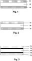
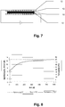
- FIGs 1 to 5 Possible arrangements of such contacted hot melt adhesive tapes are in the Figures 1 to 5 shown.
- the electrically heatable hot melt adhesive 10 is contacted on both sides and over the entire area with a metal foil 12, in particular an aluminum or copper foil.
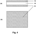
- the hotmelt adhesive 10 is also in full contact on one side with a metal foil 12 and in part on the other side with a metal net 14.
- Figure 3 shows Figure 3 a product structure in which the hot-melt adhesive 10 is contacted on both sides with a metallized plastic film, 16 each denoting the plastic film and 18 its metal coating.
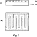
- the contacts can extend over the entire surface of the entire adhesive tape on both sides or only partially cover the surface on one or both sides, in particular in the form of lines, dots, grids, combs or other geometric shapes. In the former case, there is a current flow transverse to the surface area of the heatable hot melt adhesive (z direction), while in the second case there is exclusively or additionally a current flow within the area of the heatable hot melt adhesive material (xy direction).
- the Figures 4 and 5 illustrate such designs by way of example and without wishing to restrict the invention unnecessarily.
- 10 heatable hotmelt adhesive
- 12 metal foil
- 20 electrode structure
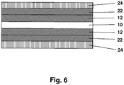
- the hot-melt adhesive sheet according to the invention comprises a layer of a pressure-sensitive adhesive.
- a pressure-sensitive adhesive This can be applied from solution, dispersion or melt to the hot-melt sticky fabric according to the invention or laminated.
- the latter then acts as a backing material for the PSA, so that there is a PSA tape which is pressure-sensitive on one side and hot-melt on the other, but advantageously on a separate backing material (such as in EP 1111021 B1 shown) waived.
- the structure of such an advantageous adhesive tape with a layer of PSA shows Figure 17 ,
- Embodiments of the fabric according to the invention can also be realized with a separate carrier material.
- the carrier material has a high thermal conductivity, in particular of at least 0.5 W / m • K, very particularly preferably of more than 1 W / m • K.
- Particularly preferred materials are polymers filled with thermally conductive fillers, such as boron nitride or aluminum oxide.
- the structure of such an advantageous adhesive tape with a carrier material shows Figure 18 ,
- PSAs All the masses known to the person skilled in the art can be used as PSAs, advantageously those based on acrylic acid and / or methacrylic acid and / or based on esters of the aforementioned compounds or those based on hydrogenated natural or synthetic rubbers, since these are particularly stable to aging and thus withstand repeated heating processes of the fabric according to the invention for a long time.
- PSAs are particularly advantageously used which themselves have a high thermal conductivity, in particular of at least 0.5 W / m • K, very particularly preferably of more than 1 W / m • K.
- Particularly preferred materials are with thermally conductive fillers, e.g. Boron nitride or aluminum oxide, filled PSAs.
- the PSA can be covered with a separating covering material.
- a cover material such.
- film materials here are PP (polypropylene), BOPP (biaxially oriented PP), MOPP (monoaxially oriented PP), PET (polyethylene terephthalate), PVC (polyvinyl chloride), PUR (polyurethane), PE (polyethylene), PE / EVA (polyethylene) / Ethylene vinyl acetate copolymers) and EPDM (ethene / propylene-diene terpolymers).
- Release papers glassine papers, kraft papers, polyolefinically coated papers
- the structure of such an advantageous adhesive tape with a covering material shows Figure 19 ,
- Covering materials are particularly advantageously used which themselves have a high thermal conductivity, in particular of at least 0.5 W / m • K, very particularly preferably of more than 1 W / m • K.
- Particularly preferred materials are with thermally conductive fillers, e.g. Boron nitride or aluminum oxide, filled polymers.
- the heat required for melting the hot-melt adhesive can be better introduced through particularly thermally conductive PSAs, backing and / or covering materials, which is e.g. leads to shorter cycle times in the application.
- the hot melt, heatable layer is constructed from several layers of the same or similar materials. In particular in the case of heating by electrical resistance in the z direction, possible short circuits due to filler agglomerates are avoided.
- the heatable fabric is equipped with a mechanism which, when the fabric is heated for the first time, leads to an increase in cohesion of the hot-melt, heatable layer and / or a further hot-melt adhesive or pressure-sensitive adhesive layer.
- This could, for example, be an increase in the crosslinking density through a thermally initiated postcrosslinking, which is initiated in particular by the heating of the fabric itself.
- Such a flat structure is advantageously used in such a way that the bond is first produced with at least one substrate, then the first heating is carried out and the bond is thus solidified.
- the fabric according to the invention has a high heating capacity and is suitable for use as a hot-melt adhesive tape which, in addition to bonding, also fulfills a heating function, for example for bonding heated mirrors.
- the invention relates to the use of the above-described flat structures for bonding substrates in the automotive industry, furthermore also to the use for heating substrates bonded to such flat structures, in particular in the automotive industry.
- the heating of the substrate is brought about by heating the flat structure, the flat structure being applied to at least one surface which is equipped with at least one electrical contact, the surface in particular being one of the glued substrates itself (but not have to be).
- a 200 ⁇ m thick strip of the fabric according to the invention was sealed onto an untreated polyester film (Mitsubishi Hostaphan) using a heating press under vacuum at a temperature of 140 ° C.
- a 20 mm wide strip was cut out of it, and after conditioning in the room climate for 24 h, the heating foil was again removed from the polyester support subtracted and the force measured. Neither heating foil nor polyester foil was supported or fixed, so that a T-shaped peeling occurred.
- the measurement results are given in N / cm and are averaged from three measurements. All measurements were carried out at room temperature under air-conditioned conditions.
- the temperature increase after the application of electrical voltage was measured.
- the temperature was measured using a Pt100 thermal sensor.
- a 200 ⁇ m thick film of the heatable hot melt adhesive is provided on both sides with a 40 x 80 mm 2 and 50 ⁇ m thick copper foil (hot laminated) and a direct voltage of 12.8 volts is applied to these electrodes via a transformer.
- the upper side was positive, the lower side was negatively charged.
- the temperature was measured directly on the surface of the copper foil after 600 seconds and stated in ° C.
- the hot melt, heatable carrier material became analogous with a comb-shaped conductor structure, which was on a PET carrier material Figure 5 contacted on one side (hot-laminated) and applied on the other side to a glass plate using a 75 ⁇ m thick pressure-sensitive adhesive film (resin-modified acrylate pressure-sensitive adhesive).
- the area of the electrode was 180 cm 2 .
- a DC voltage of 12.8 volts was applied to this flexible circuit board via a transformer. The temperature was measured directly on the surface of the copper foil after 600 seconds and stated in ° C.
- thermoplastics were compounded with the conductive fillers using a Haake Rheomix type kneader. A temperature of 140 ° C. and a speed of 120 min -1 were used over a period of 45 min.
- Sheet materials with a thickness of 200 ⁇ m were produced from the polymer compounds using a vacuum press.
- Table 1 Mixtures of the carrier materials produced Example no. polymer polymer type filler type Proportion of filler [% by weight] 1 ExxonMobil Escorene Ultra FL 00014 EVA, 14% VA Soot Degussa Printex XE2 10 2 ExxonMobil Escorene Ultra FL 00014 EVA Hyperion Catalysis MB 2525-00 (EVA masterbatch with 25% carbon nanotubes) 20 3 ExxonMobil Escorene Ultra FL 00014 EVA 14% VA Graphite Timcal Timrex KS6 36 4 ExxonMobil Escorene Ultra FL 00014 EVA, 14% VA Soot Degussa Printex XE2 15 5 ExxonMobil Escorene Ultra FL 00014 EVA 14% VA Graphite Timcal Timrex KS6 45 6 Dow Primacor 3460 EAA Carbon black Printex XE2 16 counterexamples 7 Basell Hostalen HS GC 7260 F2 HD
- Example 1 The solvent was removed from the PSA prepared for Example 9. The further production of the sample was carried out as described above. This pattern was then made according to Example 1 WO 2004/081136 cross-linked by electron radiation. The dose was 50 kGy at an acceleration voltage of 220 kV.
- the values shown in Table 2 make it clear that Examples 1 to 6 have good hot-melt adhesive properties.
- the adhesive strength can be controlled by the amount and type of filler additive and by the monomer / comonomer composition. The adhesive strength drops due to high proportions of the filling material.
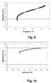
- Test B was carried out to determine the heatability and the PTC effect. Since the piping was carried out in the z direction through the 200 ⁇ m thick fabric, a low filler content was sufficient to produce sufficient conductivity, so that only samples 1 to 3 were tested. The conductivity of the other samples was too high, so that the voltage was reduced due to the current limitation of the power supplies.
- Figure 8 shows the current, voltage and temperature curve in test B for sample 1, from which the resistance / temperature curve was calculated in Figure 9 that depicted the PTC effect.
- Figure 10 shows such a PTC curve for pattern 2, Figure 11 for pattern 3.
- Test C was also carried out to determine the heatability and the PTC effect.
- the more conductive patterns 4, 5 and 6 were used because the distance between the conductor tracks was 1.5 mm.
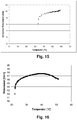
- Figure 12 shows the current, voltage and temperature curve in test C for sample 4, from which the resistance / temperature curve in was calculated Figure 13 that depicted the PTC effect.
- Figure 14 shows such a PTC curve for pattern 5 and Figure 15 for pattern 6.
- a PSC with PTC effect was examined using test B (sample 9).
- Such PSAs are in WO 2004/081136 A1 described.
- the investigation shows that the PTC effect, which can be determined in the temperature range from 22 to about 40 ° C., is much less pronounced than that in the examples according to the invention.
- the heatable PSA shows an NTC effect (negative temperature coefficient) above 40 ° C, which is disadvantageous in many applications.
- the crosslinking means that the PSA does not melt.
- hotmelt adhesives would not be suitable for use in automotive bonding at least if the adhesive were to be designed as an (electrically) heatable adhesive and this adhesive should be used to heat substrates bonded with such flat structures. In this regard, the person skilled in the art would have had to forego the advantages of gluing with hot-melt adhesives.
- the implementation of the PTC effect has made it possible to offer hot melt adhesives which are self-regulating insofar as they resist the heat-generating moment (here the electrical current) when high values are reached. It can thus be achieved that, due to the system, there is a maximum temperature which the temperature during the heating process cannot exceed. It can thus be avoided that the hotmelt adhesives come into the temperature range of the melting or softening temperature as a result of the heating, the bonding running the risk of deteriorating significantly or even becoming detached.
Landscapes
- Chemical & Material Sciences (AREA)
- Organic Chemistry (AREA)
- Engineering & Computer Science (AREA)
- Microelectronics & Electronic Packaging (AREA)
- Dispersion Chemistry (AREA)
- Ceramic Engineering (AREA)
- Physics & Mathematics (AREA)
- Electromagnetism (AREA)
- Adhesives Or Adhesive Processes (AREA)
- Adhesive Tapes (AREA)
- Surface Heating Bodies (AREA)
- Resistance Heating (AREA)
Claims (21)
- Structure plane présentant au moins une couche d'une masse adhésive dans laquelle de la chaleur peut être produite, la couche étant en contact avec une couche de fond, caractérisée en ce que la masse adhésive est une masse adhésive thermofusible et un conducteur à froid, la structure plane étant adhésive thermofusible en ce que, après l'application sous forme de masse fondue sur la couche de fond et refroidissement consécutif, l'adhésivité à température ambiante selon la norme ASTM D 3330-04 à une vitesse de pelage de 300 mm/min sur la couche de fond de collage est supérieure à 1 N/cm.
- Structure plane selon la revendication 1, caractérisée en ce que la production de chaleur est provoquée par un courant électrique.
- Structure plane selon au moins l'une quelconque des revendications précédentes, caractérisée en ce que ladite au moins une couche de masse adhésive thermofusible comprend(a) au moins un composant adhésif et(b) au moins un matériau électriquement conducteur.
- Structure plane selon la revendication 3, caractérisée en ce que le matériau électriquement conducteur est le graphite et/ou la suie, en particulier la suie conductrice.
- Structure plane selon au moins l'une quelconque des revendications 3 ou 4, caractérisée en ce que ledit au moins un matériau électriquement conducteur présente une proportion massique de 2 à 60% en poids, en particulier de 5 à 50% en poids, par rapport à la masse adhésive thermofusible.
- Structure plane selon au moins l'une quelconque des revendications 3 à 5, caractérisée en ce que le matériau électriquement conducteur présente, dans au moins une direction spatiale, une dilatation qui n'est pas supérieure à 500 nm, de préférence pas supérieure à 200 nm, de manière particulièrement préférée pas supérieure à 50 nm.
- Structure plane selon la revendication 6, caractérisée en ce que des nanotubes de carbone (Carbon Nanotubes) et/ou des nanofibres de carbone (Carbon Nanofibers) sont utilisés comme matériau électriquement conducteur.
- Structure plane selon au moins l'une quelconque des revendications précédentes, caractérisée en ce que la masse adhésive thermofusible est une telle masse à base de polymères partiellement cristallins ou le composant adhésif est additionné de polymères cristallins.
- Structure plane selon la revendication 8, caractérisée en ce que la masse adhésive thermofusible contient au moins 30% en poids de polymères cristallins, préférablement au moins 50% en poids de polymères cristallins, plus préférablement 100% en poids de polymères cristallins.
- Structure plane selon la revendication 9, caractérisée en ce qu'il s'agit, pour les polymères partiellement cristallins, de polyoléfines, de copolymères de polyoléfines, d'iononomères, de polyamides et/ou de copolymères de polyamides.
- Structure plane selon au moins l'une quelconque des revendications précédentes, caractérisée par
au moins une mise en contact électriquement conductrice, la mise en contact étant réalisée en particulier par une feuille métallique, un filet métallique, une feuille en matériau synthétique métallisée et/ou une métallisation de la surface de la masse adhésive thermofusible. - Structure plane selon au moins l'une quelconque des revendications précédentes, caractérisée en ce que ladite au moins une couche de la masse adhésive thermofusible présente au moins une charge dotée d'une capacité thermique élevée, en particulier choisie dans le groupe constitué par l'aluminium, le béryllium, le bore, le calcium, le fer, le graphite, le potassium, le cuivre, le magnésium, le phosphore ou des composés des substances susmentionnées, en particulier l'oxyde d'aluminium, le chlorure d'aluminium, le carbonate de calcium, le chlorure de calcium, le sulfate de cuivre, la magnétite, l'hématite, le carbonate de magnésium, le chlorure de magnésium, le chlorure de phosphore, l'oxyde de phosphore.
- Structure plane selon au moins l'une quelconque des revendications précédentes, caractérisée par au moins une deuxième couche d'une masse adhésive thermofusible.
- Structure plane selon au moins l'une quelconque des revendications précédentes, caractérisée par au moins une autre couche, constituée par une masse autoadhésive, de préférence une masse autoadhésive présentant une conductibilité thermique d'au moins 0,5 W/m ∗ K, de préférence d'au moins 1 W/m ∗K.
- Structure plane selon la revendication 14, caractérisée en ce que la masse autoadhésive est une telle masse à base d'acide acrylique et/ou d'acide méthacrylique et/ou à base d'esters des composés susmentionnés ou une telle masse à base de caoutchouc naturel ou de synthèse hydrogéné.
- Structure plane selon l'une quelconque des revendications 14 ou 15, caractérisée par au moins un matériau de recouvrement, en particulier un papier de séparation ou une feuille en matériau synthétique pouvant être pelée de la masse autoadhésive, tout particulièrement un matériau de recouvrement présentant une conductibilité thermique d'au moins 0,5 W/m ∗ K, de préférence d'au moins 1 W/m ∗ K.
- Structure plane selon au moins l'une quelconque des revendications précédentes, caractérisée par au moins un matériau support, en particulier une feuille en matériau synthétique, tout particulièrement un matériau support présentant une conductibilité thermique d'au moins 0,5 W/m ∗ K, de préférence d'au moins 1 W/m ∗ K.
- Structure plane selon au moins l'une quelconque des revendications précédentes, caractérisée en ce que la structure plane pouvant être chauffée est pourvue d'un mécanisme qui provoque, lors du premier chauffage de la structure plane, une augmentation de la cohésion de la couche adhésive thermofusible pouvant être chauffée et/ou d'une autre couche adhésive thermofusible ou couche autoadhésive.
- Utilisation d'une structure plane selon l'une quelconque des revendications 1 à 18 pour le collage de substrats dans l'industrie automobile.
- Utilisation d'une structure plane selon au moins l'une quelconque des revendications 1 à 18 pour le chauffage de substrats collés par de telles structures planes, en particulier dans l'industrie automobile.
- Utilisation selon la revendication 20, caractérisée en ce que le chauffage du substrat est provoqué par chauffage de la structure plane, la structure plane étant appliquée sur une sous-couche qui est pourvue d'au moins un contact électrique, la sous-couche étant en particulier l'un des substrats collés eux-mêmes.
Applications Claiming Priority (2)
| Application Number | Priority Date | Filing Date | Title |
|---|---|---|---|
| DE102007007617A DE102007007617A1 (de) | 2007-02-13 | 2007-02-13 | Intrinsisch erwärmbare heißschmelzklebrige Flächengebilde |
| PCT/EP2008/051250 WO2008098847A1 (fr) | 2007-02-13 | 2008-02-01 | Tissus thermofusibles pouvant être chauffés intrinsèquement |
Publications (2)
| Publication Number | Publication Date |
|---|---|
| EP2118911A1 EP2118911A1 (fr) | 2009-11-18 |
| EP2118911B1 true EP2118911B1 (fr) | 2020-01-15 |
Family
ID=39367533
Family Applications (1)
| Application Number | Title | Priority Date | Filing Date |
|---|---|---|---|
| EP08708559.3A Active EP2118911B1 (fr) | 2007-02-13 | 2008-02-01 | Tissus thermofusibles pouvant être chauffés intrinsèquement |
Country Status (10)
| Country | Link |
|---|---|
| US (1) | US20100038025A1 (fr) |
| EP (1) | EP2118911B1 (fr) |
| JP (1) | JP2010518590A (fr) |
| KR (1) | KR101549981B1 (fr) |
| CN (1) | CN101681703B (fr) |
| DE (1) | DE102007007617A1 (fr) |
| ES (1) | ES2773844T3 (fr) |
| MX (1) | MX2009007930A (fr) |
| TW (1) | TW200848488A (fr) |
| WO (1) | WO2008098847A1 (fr) |
Families Citing this family (38)
| Publication number | Priority date | Publication date | Assignee | Title |
|---|---|---|---|---|
| DE102008034748A1 (de) | 2008-07-24 | 2010-01-28 | Tesa Se | Flexibles beheiztes Flächenelement |
| DE102008049850A1 (de) * | 2008-10-01 | 2010-04-08 | Tesa Se | Wärmeleitende Haftklebemasse |
| DE102008063849A1 (de) * | 2008-12-19 | 2010-06-24 | Tesa Se | Beheiztes Flächenelement und Verfahren zu seiner Befestigung |
| DE102009005517A1 (de) * | 2009-01-20 | 2010-07-22 | Tesa Se | Verfahren zur Korrosionsschutzbehandlung |
| DE102009010437A1 (de) | 2009-02-26 | 2010-09-02 | Tesa Se | Beheiztes Flächenelement |
| CN101602867B (zh) * | 2009-07-09 | 2011-04-13 | 浙江三力士橡胶股份有限公司 | 一种改性氯丁橡胶v带及其制备方法 |
| DE102009055099A1 (de) | 2009-12-21 | 2011-06-22 | tesa SE, 20253 | Hitzeaktiviert verklebbare Flächenelemente |
| DE102010003440A1 (de) | 2010-03-30 | 2011-10-06 | Lisa Dräxlmaier GmbH | Verfahren zum Herstellen von Innenverkleidungsteilen durch Kaschieren sowie Innenverkleidungsteil |
| TWI406755B (zh) * | 2010-10-04 | 2013-09-01 | Advanced Int Multitech Co Ltd | Manufacturing Method of Composite Workpiece with Embedded Magnetic Element |
| US10377925B2 (en) * | 2011-02-10 | 2019-08-13 | Futurecarbon Gmbh | Adhesive material with carbon material and method for its production and use |
| DE102011005901A1 (de) | 2011-03-22 | 2012-09-27 | Lisa Dräxlmaier GmbH | Kaltkaschierung mit Strahlung |
| DE102011080724A1 (de) | 2011-08-10 | 2013-02-14 | Tesa Se | Elektrisch leitfähige hitzeaktivierbare Klebemasse |
| DE102011080729A1 (de) | 2011-08-10 | 2013-02-14 | Tesa Se | Elektrisch leitfähige Haftklebemasse und Haftklebeband |
| DE102011082425A1 (de) * | 2011-09-09 | 2013-03-14 | Hochschule für Nachhaltige Entwicklung Eberswalde | Vorrichtung und Verfahren zur permanenten Prüfung von Klebeverbindungen |
| EP2578624A1 (fr) | 2011-10-06 | 2013-04-10 | Henkel Italia S.p.A. | Thermistors PTC polymériques |
| DE102014208094A1 (de) * | 2014-04-29 | 2015-10-29 | MAGNA STEYR Engineering AG & Co KG | Vorrichtung zum Aushärten eines elektrisch leitenden Klebstoffes |
| KR101578479B1 (ko) * | 2014-05-07 | 2015-12-28 | 신충근 | 천연 접착제 함유 세라믹 발열 장치 |
| US10373745B2 (en) | 2014-06-12 | 2019-08-06 | LMS Consulting Group | Electrically conductive PTC ink with double switching temperatures and applications thereof in flexible double-switching heaters |
| US10077372B2 (en) | 2014-06-12 | 2018-09-18 | Lms Consulting Group, Llc | Electrically conductive PTC screen printable ink with double switching temperatures and method of making the same |
| CN104669708B (zh) * | 2015-02-12 | 2017-01-18 | 张继承 | 一种地暖加热片及其制造方法 |
| DE102015207818A1 (de) * | 2015-04-28 | 2016-11-17 | Benecke-Kaliko Ag | Leitfähige Folie für eine Widerstandsheizung |
| EP3170657B1 (fr) | 2015-11-19 | 2020-09-09 | 3M Innovative Properties Company | Film adhésif structurel multicouche |
| CN106916546A (zh) * | 2015-12-28 | 2017-07-04 | 严能进 | 一种增强型免钉胶薄片及其制造方法 |
| US10822512B2 (en) | 2016-02-24 | 2020-11-03 | LMS Consulting Group | Thermal substrate with high-resistance magnification and positive temperature coefficient |
| EP3420041A4 (fr) * | 2016-02-24 | 2019-11-13 | LMS Consulting Group | Encre ctp électroconductrice à températures de double commutation et ses applications dans des dispositifs de chauffage souples à double commutation |
| US11332632B2 (en) | 2016-02-24 | 2022-05-17 | Lms Consulting Group, Llc | Thermal substrate with high-resistance magnification and positive temperature coefficient ink |
| DE102016203497A1 (de) * | 2016-03-03 | 2017-09-07 | Röchling Automotive SE & Co. KG | Heizeinrichtung für einen Kfz-Betriebsflüssigkeitstank mit einem PTC-Kunststoffkörper |
| CN105670550B (zh) * | 2016-03-31 | 2017-11-14 | 东莞新能源科技有限公司 | 一种导热胶及含有该导热胶的二次电池 |
| KR101911468B1 (ko) | 2017-03-14 | 2019-01-04 | 한국생산기술연구원 | 열가소성 엘라스토머 조성물 및 그를 포함하는 열융착 필름 |
| WO2019157805A1 (fr) * | 2018-02-13 | 2019-08-22 | 陈志勇 | Matériau de semelle intermédiaire et son procédé de fabrication, matériau de semelle d'usure, film adhésif thermofusible, appareil de stratification et semelle |
| DE102018203430A1 (de) * | 2018-03-07 | 2019-09-12 | Voestalpine Stahl Gmbh | Flächenelektrobauteil und verfahren zur herstellung |
| CN108641610A (zh) * | 2018-04-25 | 2018-10-12 | 常州驰科光电科技有限公司 | 一种高强度自粘性导电导热膜及其制备方法 |
| JP7172288B2 (ja) * | 2018-08-28 | 2022-11-16 | 東洋インキScホールディングス株式会社 | 導電性ホットメルト接着剤組成物、および積層体 |
| DE102018133112A1 (de) * | 2018-12-20 | 2020-06-25 | Lisa Dräxlmaier GmbH | Fahrzeugbauteil mit zumindest einem elektrisch beheizbaren Heizbereich und Verfahren zum Herstellen desselben |
| CN112312597A (zh) * | 2019-09-12 | 2021-02-02 | 江苏烯泰石墨烯应用技术研究院有限公司 | 高均匀性电加热膜及其制备方法 |
| DE202020101775U1 (de) * | 2020-04-01 | 2020-05-26 | Certoplast Technische Klebebänder Gmbh | Klebeband, insbesondere Kabelwickelband zum Umwickeln von Kabeln in Automobilen |
| WO2024167943A1 (fr) * | 2023-02-06 | 2024-08-15 | Applied Cavitation, Inc. | Procédés et systèmes de circuit imprimé sur un substrat pour électronique étirable |
| TWI857826B (zh) * | 2023-10-27 | 2024-10-01 | 聚鼎科技股份有限公司 | 過電流保護元件 |
Family Cites Families (17)
| Publication number | Priority date | Publication date | Assignee | Title |
|---|---|---|---|---|
| US4775778A (en) | 1976-10-15 | 1988-10-04 | Raychem Corporation | PTC compositions and devices comprising them |
| US4237441A (en) | 1978-12-01 | 1980-12-02 | Raychem Corporation | Low resistivity PTC compositions |
| EP0063440B1 (fr) | 1981-04-02 | 1989-10-04 | RAYCHEM CORPORATION (a Delaware corporation) | Réticulation par irradiation des polymères conducteurs de CTP |
| DE3443789A1 (de) * | 1983-12-02 | 1985-06-27 | Osaka Soda Co. Ltd., Osaka | Elektrische leitende klebstoffmasse |
| JPS61151283A (ja) * | 1984-12-24 | 1986-07-09 | Dainippon Printing Co Ltd | 導電性接着剤 |
| KR890005758A (ko) | 1987-09-09 | 1989-05-16 | 원본미기재 | 전도성 중합체 조성물 |
| KR100224945B1 (ko) | 1988-09-20 | 1999-10-15 | 허버트 지. 버카드 | 전도성 중합체 조성물을 포함하는 전기장치 |
| JPH0320378A (ja) * | 1989-06-17 | 1991-01-29 | Fujikura Ltd | 導電性接着剤 |
| JPH03131679A (ja) * | 1989-10-17 | 1991-06-05 | Fujikura Ltd | 導電性接着剤 |
| GB9109856D0 (en) | 1991-05-04 | 1991-06-26 | Cabot Plastics Ltd | Conductive polymer compositions |
| JP2647589B2 (ja) * | 1992-01-27 | 1997-08-27 | 矢崎総業株式会社 | 電磁波遮蔽用複合シート |
| US6059997A (en) * | 1995-09-29 | 2000-05-09 | Littlelfuse, Inc. | Polymeric PTC compositions |
| DE29922805U1 (de) | 1999-12-24 | 2001-05-03 | Coroplast Fritz Müller GmbH & Co. KG, 42279 Wuppertal | Doppelseitiges Klebeband |
| DE10210661A1 (de) * | 2001-11-13 | 2003-05-28 | Fraunhofer Ges Forschung | Induktiv härtbare und wieder lösbare Verbindungen |
| DE10310722A1 (de) | 2003-03-10 | 2004-09-23 | Tesa Ag | Elektrisch erwärmbare Haftklebemasse |
| TWI463615B (zh) * | 2004-11-04 | 2014-12-01 | 台灣積體電路製造股份有限公司 | 以奈米管為基礎之具方向性導電黏著 |
| US8045846B2 (en) * | 2005-01-27 | 2011-10-25 | Sk Kaken Co., Ltd. | Composition for heat-storage object formation, heat-storage object, and process for producing heat-storage object |
-
2007
- 2007-02-13 DE DE102007007617A patent/DE102007007617A1/de not_active Withdrawn
-
2008
- 2008-02-01 CN CN200880011884.3A patent/CN101681703B/zh not_active Expired - Fee Related
- 2008-02-01 JP JP2009549811A patent/JP2010518590A/ja not_active Withdrawn
- 2008-02-01 KR KR1020097019036A patent/KR101549981B1/ko not_active Expired - Fee Related
- 2008-02-01 MX MX2009007930A patent/MX2009007930A/es active IP Right Grant
- 2008-02-01 WO PCT/EP2008/051250 patent/WO2008098847A1/fr not_active Ceased
- 2008-02-01 EP EP08708559.3A patent/EP2118911B1/fr active Active
- 2008-02-01 US US12/526,806 patent/US20100038025A1/en not_active Abandoned
- 2008-02-01 ES ES08708559T patent/ES2773844T3/es active Active
- 2008-02-12 TW TW097104882A patent/TW200848488A/zh unknown
Non-Patent Citations (1)
| Title |
|---|
| None * |
Also Published As
| Publication number | Publication date |
|---|---|
| ES2773844T3 (es) | 2020-07-15 |
| JP2010518590A (ja) | 2010-05-27 |
| KR101549981B1 (ko) | 2015-09-03 |
| CN101681703B (zh) | 2015-01-07 |
| US20100038025A1 (en) | 2010-02-18 |
| EP2118911A1 (fr) | 2009-11-18 |
| KR20100015308A (ko) | 2010-02-12 |
| DE102007007617A1 (de) | 2008-08-14 |
| CN101681703A (zh) | 2010-03-24 |
| MX2009007930A (es) | 2009-08-18 |
| TW200848488A (en) | 2008-12-16 |
| WO2008098847A1 (fr) | 2008-08-21 |
Similar Documents
| Publication | Publication Date | Title |
|---|---|---|
| EP2118911B1 (fr) | Tissus thermofusibles pouvant être chauffés intrinsèquement | |
| EP2148337B1 (fr) | Elément de surface chauffé et flexible | |
| EP2224784B1 (fr) | Elément de surface chauffé | |
| EP2199063A2 (fr) | Elément de surface chauffé et son procédé de fixation | |
| EP1606368B1 (fr) | Materiaux plats adhesifs pouvant etre chauffes intrinsequement | |
| DE68923400T2 (de) | Haftkleber mit Haftung auf plastifizierten Vinyluntergründen. | |
| EP2516572B1 (fr) | Éléments plans pouvant être collés par activation thermique | |
| EP2742106B1 (fr) | Matière adhésive électroconductrice et bande adhésive | |
| EP2087056B1 (fr) | Élément plat doté d'un adhésif activé thermiquement | |
| WO2004050782A1 (fr) | Bande auto-adhesive antistatique | |
| EP3137566B1 (fr) | Procédé pour réaliser un collage sur des surfaces sensibles aux perméats | |
| DE102004029589A1 (de) | Elektrisch anisotrop leitfähiger Schmelzkleber zur Implantierung von elektrischen Modulen in einen Kartenkörper | |
| DE102007063020A1 (de) | Verfahren zur Herstellung eines Antennensystems | |
| DE69830620T2 (de) | Wärmehärtbarer klebstoff | |
| EP2210906B1 (fr) | Bandes adhésives pour applications électroniques | |
| EP4506430A1 (fr) | Ruban adhésif, composite collé et procédé de libération électrique du composite collé | |
| EP4168506A1 (fr) | Bande adhésive conductrice double-face sensible à la pression |
Legal Events
| Date | Code | Title | Description |
|---|---|---|---|
| PUAI | Public reference made under article 153(3) epc to a published international application that has entered the european phase |
Free format text: ORIGINAL CODE: 0009012 |
|
| 17P | Request for examination filed |
Effective date: 20090914 |
|
| AK | Designated contracting states |
Kind code of ref document: A1 Designated state(s): AT BE BG CH CY CZ DE DK EE ES FI FR GB GR HR HU IE IS IT LI LT LU LV MC MT NL NO PL PT RO SE SI SK TR |
|
| DAX | Request for extension of the european patent (deleted) | ||
| 17Q | First examination report despatched |
Effective date: 20150918 |
|
| RAP1 | Party data changed (applicant data changed or rights of an application transferred) |
Owner name: TESA SE |
|
| STAA | Information on the status of an ep patent application or granted ep patent |
Free format text: STATUS: EXAMINATION IS IN PROGRESS |
|
| GRAP | Despatch of communication of intention to grant a patent |
Free format text: ORIGINAL CODE: EPIDOSNIGR1 |
|
| STAA | Information on the status of an ep patent application or granted ep patent |
Free format text: STATUS: GRANT OF PATENT IS INTENDED |
|
| RIC1 | Information provided on ipc code assigned before grant |
Ipc: C09J 9/02 20060101ALI20190816BHEP Ipc: H01C 7/02 20060101AFI20190816BHEP Ipc: C09J 133/06 20060101ALI20190816BHEP Ipc: C09J 7/28 20180101ALI20190816BHEP Ipc: C09J 7/35 20180101ALI20190816BHEP |
|
| INTG | Intention to grant announced |
Effective date: 20190924 |
|
| GRAS | Grant fee paid |
Free format text: ORIGINAL CODE: EPIDOSNIGR3 |
|
| GRAA | (expected) grant |
Free format text: ORIGINAL CODE: 0009210 |
|
| STAA | Information on the status of an ep patent application or granted ep patent |
Free format text: STATUS: THE PATENT HAS BEEN GRANTED |
|
| AK | Designated contracting states |
Kind code of ref document: B1 Designated state(s): AT BE BG CH CY CZ DE DK EE ES FI FR GB GR HR HU IE IS IT LI LT LU LV MC MT NL NO PL PT RO SE SI SK TR |
|
| REG | Reference to a national code |
Ref country code: CH Ref legal event code: EP Ref country code: GB Ref legal event code: FG4D Free format text: NOT ENGLISH |
|
| REG | Reference to a national code |
Ref country code: IE Ref legal event code: FG4D Free format text: LANGUAGE OF EP DOCUMENT: GERMAN |
|
| REG | Reference to a national code |
Ref country code: DE Ref legal event code: R096 Ref document number: 502008017007 Country of ref document: DE |
|
| REG | Reference to a national code |
Ref country code: AT Ref legal event code: REF Ref document number: 1225868 Country of ref document: AT Kind code of ref document: T Effective date: 20200215 |
|
| PGFP | Annual fee paid to national office [announced via postgrant information from national office to epo] |
Ref country code: ES Payment date: 20200322 Year of fee payment: 13 |
|
| REG | Reference to a national code |
Ref country code: NL Ref legal event code: MP Effective date: 20200115 |
|
| PGFP | Annual fee paid to national office [announced via postgrant information from national office to epo] |
Ref country code: FR Payment date: 20200227 Year of fee payment: 13 |
|
| REG | Reference to a national code |
Ref country code: ES Ref legal event code: FG2A Ref document number: 2773844 Country of ref document: ES Kind code of ref document: T3 Effective date: 20200715 |
|
| REG | Reference to a national code |
Ref country code: LT Ref legal event code: MG4D |
|
| PG25 | Lapsed in a contracting state [announced via postgrant information from national office to epo] |
Ref country code: NO Free format text: LAPSE BECAUSE OF FAILURE TO SUBMIT A TRANSLATION OF THE DESCRIPTION OR TO PAY THE FEE WITHIN THE PRESCRIBED TIME-LIMIT Effective date: 20200415 Ref country code: PT Free format text: LAPSE BECAUSE OF FAILURE TO SUBMIT A TRANSLATION OF THE DESCRIPTION OR TO PAY THE FEE WITHIN THE PRESCRIBED TIME-LIMIT Effective date: 20200607 Ref country code: NL Free format text: LAPSE BECAUSE OF FAILURE TO SUBMIT A TRANSLATION OF THE DESCRIPTION OR TO PAY THE FEE WITHIN THE PRESCRIBED TIME-LIMIT Effective date: 20200115 Ref country code: FI Free format text: LAPSE BECAUSE OF FAILURE TO SUBMIT A TRANSLATION OF THE DESCRIPTION OR TO PAY THE FEE WITHIN THE PRESCRIBED TIME-LIMIT Effective date: 20200115 |
|
| PG25 | Lapsed in a contracting state [announced via postgrant information from national office to epo] |
Ref country code: HR Free format text: LAPSE BECAUSE OF FAILURE TO SUBMIT A TRANSLATION OF THE DESCRIPTION OR TO PAY THE FEE WITHIN THE PRESCRIBED TIME-LIMIT Effective date: 20200115 Ref country code: SE Free format text: LAPSE BECAUSE OF FAILURE TO SUBMIT A TRANSLATION OF THE DESCRIPTION OR TO PAY THE FEE WITHIN THE PRESCRIBED TIME-LIMIT Effective date: 20200115 Ref country code: LV Free format text: LAPSE BECAUSE OF FAILURE TO SUBMIT A TRANSLATION OF THE DESCRIPTION OR TO PAY THE FEE WITHIN THE PRESCRIBED TIME-LIMIT Effective date: 20200115 Ref country code: IS Free format text: LAPSE BECAUSE OF FAILURE TO SUBMIT A TRANSLATION OF THE DESCRIPTION OR TO PAY THE FEE WITHIN THE PRESCRIBED TIME-LIMIT Effective date: 20200515 Ref country code: BG Free format text: LAPSE BECAUSE OF FAILURE TO SUBMIT A TRANSLATION OF THE DESCRIPTION OR TO PAY THE FEE WITHIN THE PRESCRIBED TIME-LIMIT Effective date: 20200415 |
|
| REG | Reference to a national code |
Ref country code: CH Ref legal event code: PL |
|
| REG | Reference to a national code |
Ref country code: DE Ref legal event code: R097 Ref document number: 502008017007 Country of ref document: DE |
|
| REG | Reference to a national code |
Ref country code: BE Ref legal event code: MM Effective date: 20200229 |
|
| PG25 | Lapsed in a contracting state [announced via postgrant information from national office to epo] |
Ref country code: CZ Free format text: LAPSE BECAUSE OF FAILURE TO SUBMIT A TRANSLATION OF THE DESCRIPTION OR TO PAY THE FEE WITHIN THE PRESCRIBED TIME-LIMIT Effective date: 20200115 Ref country code: RO Free format text: LAPSE BECAUSE OF FAILURE TO SUBMIT A TRANSLATION OF THE DESCRIPTION OR TO PAY THE FEE WITHIN THE PRESCRIBED TIME-LIMIT Effective date: 20200115 Ref country code: LT Free format text: LAPSE BECAUSE OF FAILURE TO SUBMIT A TRANSLATION OF THE DESCRIPTION OR TO PAY THE FEE WITHIN THE PRESCRIBED TIME-LIMIT Effective date: 20200115 Ref country code: EE Free format text: LAPSE BECAUSE OF FAILURE TO SUBMIT A TRANSLATION OF THE DESCRIPTION OR TO PAY THE FEE WITHIN THE PRESCRIBED TIME-LIMIT Effective date: 20200115 Ref country code: DK Free format text: LAPSE BECAUSE OF FAILURE TO SUBMIT A TRANSLATION OF THE DESCRIPTION OR TO PAY THE FEE WITHIN THE PRESCRIBED TIME-LIMIT Effective date: 20200115 Ref country code: LU Free format text: LAPSE BECAUSE OF NON-PAYMENT OF DUE FEES Effective date: 20200201 Ref country code: SK Free format text: LAPSE BECAUSE OF FAILURE TO SUBMIT A TRANSLATION OF THE DESCRIPTION OR TO PAY THE FEE WITHIN THE PRESCRIBED TIME-LIMIT Effective date: 20200115 Ref country code: MC Free format text: LAPSE BECAUSE OF FAILURE TO SUBMIT A TRANSLATION OF THE DESCRIPTION OR TO PAY THE FEE WITHIN THE PRESCRIBED TIME-LIMIT Effective date: 20200115 |
|
| PLBE | No opposition filed within time limit |
Free format text: ORIGINAL CODE: 0009261 |
|
| STAA | Information on the status of an ep patent application or granted ep patent |
Free format text: STATUS: NO OPPOSITION FILED WITHIN TIME LIMIT |
|
| PG25 | Lapsed in a contracting state [announced via postgrant information from national office to epo] |
Ref country code: LI Free format text: LAPSE BECAUSE OF NON-PAYMENT OF DUE FEES Effective date: 20200229 Ref country code: CH Free format text: LAPSE BECAUSE OF NON-PAYMENT OF DUE FEES Effective date: 20200229 |
|
| 26N | No opposition filed |
Effective date: 20201016 |
|
| PG25 | Lapsed in a contracting state [announced via postgrant information from national office to epo] |
Ref country code: IE Free format text: LAPSE BECAUSE OF NON-PAYMENT OF DUE FEES Effective date: 20200201 Ref country code: IT Free format text: LAPSE BECAUSE OF FAILURE TO SUBMIT A TRANSLATION OF THE DESCRIPTION OR TO PAY THE FEE WITHIN THE PRESCRIBED TIME-LIMIT Effective date: 20200115 |
|
| PG25 | Lapsed in a contracting state [announced via postgrant information from national office to epo] |
Ref country code: PL Free format text: LAPSE BECAUSE OF FAILURE TO SUBMIT A TRANSLATION OF THE DESCRIPTION OR TO PAY THE FEE WITHIN THE PRESCRIBED TIME-LIMIT Effective date: 20200115 Ref country code: BE Free format text: LAPSE BECAUSE OF NON-PAYMENT OF DUE FEES Effective date: 20200229 Ref country code: SI Free format text: LAPSE BECAUSE OF FAILURE TO SUBMIT A TRANSLATION OF THE DESCRIPTION OR TO PAY THE FEE WITHIN THE PRESCRIBED TIME-LIMIT Effective date: 20200115 |
|
| GBPC | Gb: european patent ceased through non-payment of renewal fee |
Effective date: 20200415 |
|
| REG | Reference to a national code |
Ref country code: AT Ref legal event code: MM01 Ref document number: 1225868 Country of ref document: AT Kind code of ref document: T Effective date: 20200201 |
|
| PG25 | Lapsed in a contracting state [announced via postgrant information from national office to epo] |
Ref country code: GB Free format text: LAPSE BECAUSE OF NON-PAYMENT OF DUE FEES Effective date: 20200415 |
|
| PG25 | Lapsed in a contracting state [announced via postgrant information from national office to epo] |
Ref country code: AT Free format text: LAPSE BECAUSE OF NON-PAYMENT OF DUE FEES Effective date: 20200201 |
|
| PG25 | Lapsed in a contracting state [announced via postgrant information from national office to epo] |
Ref country code: FR Free format text: LAPSE BECAUSE OF NON-PAYMENT OF DUE FEES Effective date: 20210228 |
|
| REG | Reference to a national code |
Ref country code: ES Ref legal event code: FD2A Effective date: 20220504 |
|
| PG25 | Lapsed in a contracting state [announced via postgrant information from national office to epo] |
Ref country code: TR Free format text: LAPSE BECAUSE OF FAILURE TO SUBMIT A TRANSLATION OF THE DESCRIPTION OR TO PAY THE FEE WITHIN THE PRESCRIBED TIME-LIMIT Effective date: 20200115 Ref country code: MT Free format text: LAPSE BECAUSE OF FAILURE TO SUBMIT A TRANSLATION OF THE DESCRIPTION OR TO PAY THE FEE WITHIN THE PRESCRIBED TIME-LIMIT Effective date: 20200115 Ref country code: CY Free format text: LAPSE BECAUSE OF FAILURE TO SUBMIT A TRANSLATION OF THE DESCRIPTION OR TO PAY THE FEE WITHIN THE PRESCRIBED TIME-LIMIT Effective date: 20200115 |
|
| PG25 | Lapsed in a contracting state [announced via postgrant information from national office to epo] |
Ref country code: GR Free format text: LAPSE BECAUSE OF FAILURE TO SUBMIT A TRANSLATION OF THE DESCRIPTION OR TO PAY THE FEE WITHIN THE PRESCRIBED TIME-LIMIT Effective date: 20200115 Ref country code: ES Free format text: LAPSE BECAUSE OF NON-PAYMENT OF DUE FEES Effective date: 20210202 |
|
| PGFP | Annual fee paid to national office [announced via postgrant information from national office to epo] |
Ref country code: DE Payment date: 20240219 Year of fee payment: 17 |
|
| REG | Reference to a national code |
Ref country code: DE Ref legal event code: R119 Ref document number: 502008017007 Country of ref document: DE |
|
| PG25 | Lapsed in a contracting state [announced via postgrant information from national office to epo] |
Ref country code: DE Free format text: LAPSE BECAUSE OF NON-PAYMENT OF DUE FEES Effective date: 20250902 |