EP2118911B1 - Intrinsically heatable hot melt adhesive sheet materials - Google Patents
Intrinsically heatable hot melt adhesive sheet materials Download PDFInfo
- Publication number
- EP2118911B1 EP2118911B1 EP08708559.3A EP08708559A EP2118911B1 EP 2118911 B1 EP2118911 B1 EP 2118911B1 EP 08708559 A EP08708559 A EP 08708559A EP 2118911 B1 EP2118911 B1 EP 2118911B1
- Authority
- EP
- European Patent Office
- Prior art keywords
- planar structure
- adhesive
- structure according
- hotmelt
- layer
- Prior art date
- Legal status (The legal status is an assumption and is not a legal conclusion. Google has not performed a legal analysis and makes no representation as to the accuracy of the status listed.)
- Active
Links
Images


Classifications
-
- H—ELECTRICITY
- H01—ELECTRIC ELEMENTS
- H01C—RESISTORS
- H01C7/00—Non-adjustable resistors formed as one or more layers or coatings; Non-adjustable resistors made from powdered conducting material or powdered semi-conducting material with or without insulating material
- H01C7/02—Non-adjustable resistors formed as one or more layers or coatings; Non-adjustable resistors made from powdered conducting material or powdered semi-conducting material with or without insulating material having positive temperature coefficient
- H01C7/027—Non-adjustable resistors formed as one or more layers or coatings; Non-adjustable resistors made from powdered conducting material or powdered semi-conducting material with or without insulating material having positive temperature coefficient consisting of conducting or semi-conducting material dispersed in a non-conductive organic material
-
- C—CHEMISTRY; METALLURGY
- C09—DYES; PAINTS; POLISHES; NATURAL RESINS; ADHESIVES; COMPOSITIONS NOT OTHERWISE PROVIDED FOR; APPLICATIONS OF MATERIALS NOT OTHERWISE PROVIDED FOR
- C09J—ADHESIVES; NON-MECHANICAL ASPECTS OF ADHESIVE PROCESSES IN GENERAL; ADHESIVE PROCESSES NOT PROVIDED FOR ELSEWHERE; USE OF MATERIALS AS ADHESIVES
- C09J133/00—Adhesives based on homopolymers or copolymers of compounds having one or more unsaturated aliphatic radicals, each having only one carbon-to-carbon double bond, and at least one being terminated by only one carboxyl radical, or of salts, anhydrides, esters, amides, imides, or nitriles thereof; Adhesives based on derivatives of such polymers
- C09J133/04—Homopolymers or copolymers of esters
- C09J133/06—Homopolymers or copolymers of esters of esters containing only carbon, hydrogen and oxygen, the oxygen atom being present only as part of the carboxyl radical
-
- C—CHEMISTRY; METALLURGY
- C09—DYES; PAINTS; POLISHES; NATURAL RESINS; ADHESIVES; COMPOSITIONS NOT OTHERWISE PROVIDED FOR; APPLICATIONS OF MATERIALS NOT OTHERWISE PROVIDED FOR
- C09J—ADHESIVES; NON-MECHANICAL ASPECTS OF ADHESIVE PROCESSES IN GENERAL; ADHESIVE PROCESSES NOT PROVIDED FOR ELSEWHERE; USE OF MATERIALS AS ADHESIVES
- C09J7/00—Adhesives in the form of films or foils
- C09J7/20—Adhesives in the form of films or foils characterised by their carriers
- C09J7/22—Plastics; Metallised plastics
-
- C—CHEMISTRY; METALLURGY
- C09—DYES; PAINTS; POLISHES; NATURAL RESINS; ADHESIVES; COMPOSITIONS NOT OTHERWISE PROVIDED FOR; APPLICATIONS OF MATERIALS NOT OTHERWISE PROVIDED FOR
- C09J—ADHESIVES; NON-MECHANICAL ASPECTS OF ADHESIVE PROCESSES IN GENERAL; ADHESIVE PROCESSES NOT PROVIDED FOR ELSEWHERE; USE OF MATERIALS AS ADHESIVES
- C09J7/00—Adhesives in the form of films or foils
- C09J7/20—Adhesives in the form of films or foils characterised by their carriers
- C09J7/28—Metal sheet
-
- C—CHEMISTRY; METALLURGY
- C09—DYES; PAINTS; POLISHES; NATURAL RESINS; ADHESIVES; COMPOSITIONS NOT OTHERWISE PROVIDED FOR; APPLICATIONS OF MATERIALS NOT OTHERWISE PROVIDED FOR
- C09J—ADHESIVES; NON-MECHANICAL ASPECTS OF ADHESIVE PROCESSES IN GENERAL; ADHESIVE PROCESSES NOT PROVIDED FOR ELSEWHERE; USE OF MATERIALS AS ADHESIVES
- C09J7/00—Adhesives in the form of films or foils
- C09J7/30—Adhesives in the form of films or foils characterised by the adhesive composition
- C09J7/35—Heat-activated
-
- C—CHEMISTRY; METALLURGY
- C09—DYES; PAINTS; POLISHES; NATURAL RESINS; ADHESIVES; COMPOSITIONS NOT OTHERWISE PROVIDED FOR; APPLICATIONS OF MATERIALS NOT OTHERWISE PROVIDED FOR
- C09J—ADHESIVES; NON-MECHANICAL ASPECTS OF ADHESIVE PROCESSES IN GENERAL; ADHESIVE PROCESSES NOT PROVIDED FOR ELSEWHERE; USE OF MATERIALS AS ADHESIVES
- C09J9/00—Adhesives characterised by their physical nature or the effects produced, e.g. glue sticks
- C09J9/02—Electrically-conducting adhesives
-
- H—ELECTRICITY
- H05—ELECTRIC TECHNIQUES NOT OTHERWISE PROVIDED FOR
- H05B—ELECTRIC HEATING; ELECTRIC LIGHT SOURCES NOT OTHERWISE PROVIDED FOR; CIRCUIT ARRANGEMENTS FOR ELECTRIC LIGHT SOURCES, IN GENERAL
- H05B3/00—Ohmic-resistance heating
- H05B3/20—Heating elements having extended surface area substantially in a two-dimensional [2D] plane, e.g. plate-heater
- H05B3/34—Heating elements having extended surface area substantially in a two-dimensional [2D] plane, e.g. plate-heater flexible, e.g. heating nets or webs
-
- H—ELECTRICITY
- H05—ELECTRIC TECHNIQUES NOT OTHERWISE PROVIDED FOR
- H05B—ELECTRIC HEATING; ELECTRIC LIGHT SOURCES NOT OTHERWISE PROVIDED FOR; CIRCUIT ARRANGEMENTS FOR ELECTRIC LIGHT SOURCES, IN GENERAL
- H05B3/00—Ohmic-resistance heating
- H05B3/84—Heating arrangements specially adapted for transparent or reflecting areas, e.g. for demisting or de-icing windows, mirrors or vehicle windshields
- H05B3/845—Heating arrangements specially adapted for transparent or reflecting areas, e.g. for demisting or de-icing windows, mirrors or vehicle windshields specially adapted for reflecting surfaces, e.g. bathroom - or rearview mirrors
-
- C—CHEMISTRY; METALLURGY
- C09—DYES; PAINTS; POLISHES; NATURAL RESINS; ADHESIVES; COMPOSITIONS NOT OTHERWISE PROVIDED FOR; APPLICATIONS OF MATERIALS NOT OTHERWISE PROVIDED FOR
- C09J—ADHESIVES; NON-MECHANICAL ASPECTS OF ADHESIVE PROCESSES IN GENERAL; ADHESIVE PROCESSES NOT PROVIDED FOR ELSEWHERE; USE OF MATERIALS AS ADHESIVES
- C09J2301/00—Additional features of adhesives in the form of films or foils
- C09J2301/10—Additional features of adhesives in the form of films or foils characterized by the structural features of the adhesive tape or sheet
- C09J2301/12—Additional features of adhesives in the form of films or foils characterized by the structural features of the adhesive tape or sheet by the arrangement of layers
- C09J2301/124—Additional features of adhesives in the form of films or foils characterized by the structural features of the adhesive tape or sheet by the arrangement of layers the adhesive layer being present on both sides of the carrier, e.g. double-sided adhesive tape
-
- C—CHEMISTRY; METALLURGY
- C09—DYES; PAINTS; POLISHES; NATURAL RESINS; ADHESIVES; COMPOSITIONS NOT OTHERWISE PROVIDED FOR; APPLICATIONS OF MATERIALS NOT OTHERWISE PROVIDED FOR
- C09J—ADHESIVES; NON-MECHANICAL ASPECTS OF ADHESIVE PROCESSES IN GENERAL; ADHESIVE PROCESSES NOT PROVIDED FOR ELSEWHERE; USE OF MATERIALS AS ADHESIVES
- C09J2301/00—Additional features of adhesives in the form of films or foils
- C09J2301/20—Additional features of adhesives in the form of films or foils characterized by the structural features of the adhesive itself
- C09J2301/208—Additional features of adhesives in the form of films or foils characterized by the structural features of the adhesive itself the adhesive layer being constituted by at least two or more adjacent or superposed adhesive layers, e.g. multilayer adhesive
-
- C—CHEMISTRY; METALLURGY
- C09—DYES; PAINTS; POLISHES; NATURAL RESINS; ADHESIVES; COMPOSITIONS NOT OTHERWISE PROVIDED FOR; APPLICATIONS OF MATERIALS NOT OTHERWISE PROVIDED FOR
- C09J—ADHESIVES; NON-MECHANICAL ASPECTS OF ADHESIVE PROCESSES IN GENERAL; ADHESIVE PROCESSES NOT PROVIDED FOR ELSEWHERE; USE OF MATERIALS AS ADHESIVES
- C09J2301/00—Additional features of adhesives in the form of films or foils
- C09J2301/30—Additional features of adhesives in the form of films or foils characterized by the chemical, physicochemical or physical properties of the adhesive or the carrier
- C09J2301/304—Additional features of adhesives in the form of films or foils characterized by the chemical, physicochemical or physical properties of the adhesive or the carrier the adhesive being heat-activatable, i.e. not tacky at temperatures inferior to 30°C
-
- C—CHEMISTRY; METALLURGY
- C09—DYES; PAINTS; POLISHES; NATURAL RESINS; ADHESIVES; COMPOSITIONS NOT OTHERWISE PROVIDED FOR; APPLICATIONS OF MATERIALS NOT OTHERWISE PROVIDED FOR
- C09J—ADHESIVES; NON-MECHANICAL ASPECTS OF ADHESIVE PROCESSES IN GENERAL; ADHESIVE PROCESSES NOT PROVIDED FOR ELSEWHERE; USE OF MATERIALS AS ADHESIVES
- C09J2301/00—Additional features of adhesives in the form of films or foils
- C09J2301/30—Additional features of adhesives in the form of films or foils characterized by the chemical, physicochemical or physical properties of the adhesive or the carrier
- C09J2301/314—Additional features of adhesives in the form of films or foils characterized by the chemical, physicochemical or physical properties of the adhesive or the carrier the adhesive layer and/or the carrier being conductive
-
- H—ELECTRICITY
- H05—ELECTRIC TECHNIQUES NOT OTHERWISE PROVIDED FOR
- H05B—ELECTRIC HEATING; ELECTRIC LIGHT SOURCES NOT OTHERWISE PROVIDED FOR; CIRCUIT ARRANGEMENTS FOR ELECTRIC LIGHT SOURCES, IN GENERAL
- H05B2203/00—Aspects relating to Ohmic resistive heating covered by group H05B3/00
- H05B2203/002—Heaters using a particular layout for the resistive material or resistive elements
- H05B2203/006—Heaters using a particular layout for the resistive material or resistive elements using interdigitated electrodes
-
- H—ELECTRICITY
- H05—ELECTRIC TECHNIQUES NOT OTHERWISE PROVIDED FOR
- H05B—ELECTRIC HEATING; ELECTRIC LIGHT SOURCES NOT OTHERWISE PROVIDED FOR; CIRCUIT ARRANGEMENTS FOR ELECTRIC LIGHT SOURCES, IN GENERAL
- H05B2203/00—Aspects relating to Ohmic resistive heating covered by group H05B3/00
- H05B2203/009—Heaters using conductive material in contact with opposing surfaces of the resistive element or resistive layer
-
- H—ELECTRICITY
- H05—ELECTRIC TECHNIQUES NOT OTHERWISE PROVIDED FOR
- H05B—ELECTRIC HEATING; ELECTRIC LIGHT SOURCES NOT OTHERWISE PROVIDED FOR; CIRCUIT ARRANGEMENTS FOR ELECTRIC LIGHT SOURCES, IN GENERAL
- H05B2203/00—Aspects relating to Ohmic resistive heating covered by group H05B3/00
- H05B2203/02—Heaters using heating elements having a positive temperature coefficient
-
- Y—GENERAL TAGGING OF NEW TECHNOLOGICAL DEVELOPMENTS; GENERAL TAGGING OF CROSS-SECTIONAL TECHNOLOGIES SPANNING OVER SEVERAL SECTIONS OF THE IPC; TECHNICAL SUBJECTS COVERED BY FORMER USPC CROSS-REFERENCE ART COLLECTIONS [XRACs] AND DIGESTS
- Y10—TECHNICAL SUBJECTS COVERED BY FORMER USPC
- Y10T—TECHNICAL SUBJECTS COVERED BY FORMER US CLASSIFICATION
- Y10T428/00—Stock material or miscellaneous articles
- Y10T428/26—Web or sheet containing structurally defined element or component, the element or component having a specified physical dimension
-
- Y—GENERAL TAGGING OF NEW TECHNOLOGICAL DEVELOPMENTS; GENERAL TAGGING OF CROSS-SECTIONAL TECHNOLOGIES SPANNING OVER SEVERAL SECTIONS OF THE IPC; TECHNICAL SUBJECTS COVERED BY FORMER USPC CROSS-REFERENCE ART COLLECTIONS [XRACs] AND DIGESTS
- Y10—TECHNICAL SUBJECTS COVERED BY FORMER USPC
- Y10T—TECHNICAL SUBJECTS COVERED BY FORMER US CLASSIFICATION
- Y10T428/00—Stock material or miscellaneous articles
- Y10T428/28—Web or sheet containing structurally defined element or component and having an adhesive outermost layer
- Y10T428/2813—Heat or solvent activated or sealable
- Y10T428/2817—Heat sealable
- Y10T428/2826—Synthetic resin or polymer
Definitions
- the invention relates to fabrics consisting of at least one layer of hot-melt adhesive and the use thereof.
- the PTC effect is exhibited by current-conducting materials that can conduct electricity better at lower temperatures than at high ones. Such materials are also called PTC thermistors; the materials behave accordingly cold conducting.
- PTC elements contacted with aluminum conductor tracks are glued.
- PTC elements are elements that resist a high current.
- the PTC element heats up when a certain current is applied, and the heat is transferred to the glass surface of the mirror via a double-sided adhesive tape.
- the temperature reached is limited by the PTC effect, since the resistance of the heating element increases with increasing temperature and thus the current flow is reduced. In this way, temperatures of 45 to 80 ° C can be achieved on the surface.
- Soot-filled, partially crystalline thermoplastics for example polyethylene, polyvinylidene fluoride, hexafluoropropylene or tetrafluoroethylene, are generally used as PTC materials.
- the state of the art is in DE 29 48 350 A1 .
- EP 0 307 205 A1 EP 0 512 703 A1 such as EP 0 852 801 A1 described in detail.
- these PTC materials are printed in the form of an ink on a network of conductor tracks that are used for contacting. The solvent contained in the ink is dried off. Such inks are used in EP 0 435 923 A1 described in detail.
- Pressure-sensitive adhesive tapes are generally used to attach the PTC element to the mirror plate.
- the pressure-sensitive adhesive tape transporting the heat from the PTC element to the mirror surface also has to meet special requirements with regard to thermal shear strength at elevated temperatures, weather resistance and pressure-sensitive tack at low temperatures.
- WO 2004081136 A and WO 2004/081095 also pressure-sensitive sheet-like structures, which are intrinsically heatable and combine the heating function with the pressure-sensitive adhesive.
- the disadvantages are the strongly decreasing PSA with increasing proportion of the heating components in the PSA and the difficulties in achieving a sufficient PTC effect with the generally amorphous PSA polymers. Hot-melt adhesives are not mentioned in these documents.
- D3 also describes a layer of a heatable adhesive that shows a PTC effect. This is also a pressure sensitive adhesive, but not a hot melt adhesive.
- a flat structure according to claim 1 comprising at least one layer within which heat can be generated, this layer being hot-melt-tacky and cold-conducting, ie having the PTC effect.
- the heat is preferably generated within the hotmelt adhesive layer by the electrical resistance. According to the invention, such fabrics can be used once or several times, and the heat generation process can also be carried out once or in a reproducible manner.
- the heat generation in the hotmelt-adhesive layer is limited by the PTC effect, so that the layer behaves in a self-regulating manner with regard to the heat development, in particular with regard to a maximum temperature value which should not be exceeded. Overheating of the fabric should thus be avoided.
- the flat structure consists of a singular layer of a heat-generating hotmelt adhesive which, for example, connects the mirror and the carrier plate.
- the contacting necessary for electrical resistance heating is then accommodated in a separate element, which can also be the mirror or the mirror support plate.
- the contacting is an integral part of the fabric.
- thermo-melt adhesive tape An important component of the fabric (hot-melt adhesive tape) according to the invention is the heatable hot-melt adhesive.
- a hot melt adhesive in the sense of the present invention is a fabric according to the invention if, after the melt-like application to the adhesive base and subsequent cooling, the adhesive strength at room temperature according to ASTM D 3330-04 (at a peeling speed of 300 mm / min on the adhesive base to be bonded) is greater than 1 N / cm, preferably greater than 3 N / cm, particularly preferably greater than 5 N / cm.
- the addition of at least one electrically conductive filler material which develops heat when current is applied is advantageous.
- graphite or carbon black can be used.
- this filler is nanoscale, i.e. in at least one spatial dimension it has an extent of not more than 500 nm, preferably not more than 200 nm, particularly preferably not more than 50 nm.
- conductive carbon black for example Printex® XE from Degussa
- carbon nanotubes carbon nanotubes; e.g.
- the form of the effect of the electrical heatability of the hot-melt adhesive can be determined by the degree of filling, that is to say the mass fraction, of the filler material in the hot-melt adhesive.
- the degree of filling is advantageously between 1 and 60% by weight. Between 5 and 50% by weight of filler material is very preferably used.
- the conductivity and thus also the achievable temperature and heating rate depend, among other things, on the degree of filling. By increasing the filling level, higher conductivities and possibly also higher temperatures can be achieved. Furthermore, the electrical conductivity and thus the heatability of the hotmelt adhesive is also dependent on the base polymer of the adhesive component.
- a further improvement of the carrier material can be achieved by adding at least one filler with a high heat capacity, in particular with a heat capacity of more than 0.7 J / gK. Due to the buffer function, this leads to a more even heating behavior and an extended release of heat after the active heat generation process has ended.
- Fillers with a high heat capacity which can be used advantageously according to the invention are, for example, aluminum, beryllium, boron, calcium, iron, graphite, potassium, copper, magnesium, phosphorus or compounds of the aforementioned substances, in particular aluminum oxide and -chloride, calcium carbonate, calcium chloride, copper sulfate, magnetite, haematite, magnesium carbonate and -chloride, phosphorus chloride, phosphorus oxide.
- Multi-phase systems are preferably used, in particular those in which at least one phase in the temperature range of the occurrence of the PTC effect experiences a volume expansion due to the heating, which according to generally accepted scientific explanation at least partially causes the PTC effect (see J. Meyer in Polymer Engineering and Science, 13 (1973), pp. 462-468 ).
- Polymers or polymer blends filled with a further filler are also multi-phase in the sense of the invention.
- the hot-melt adhesive preferably contains at least 30% by weight of partially crystalline polymers, and a proportion of partially-crystalline polymers of at least 50% by weight in the hot-melt adhesive is even better. It has been found that the suitability for achieving the PTC effect is surprisingly greatly improved with the proportion of partially crystalline systems - compared to PSAs which lose their pressure-sensitive properties with increasing proportion of the partially crystalline component and therefore have only lower proportions of partially crystalline systems. Hot melt adhesives are therefore well suited for the application of the PTC effect beyond expectations.
- DSC differential scanning calorimetry
- Polyolefins eg low-density polyethylene
- polyolefins eg Ethylene vinyl acetate (EVA), ethylene acrylic acid (EAA), ethylene methacrylic acid (EMAA), ethylene ethyl acrylate, ethylene butyl acrylate), ionomers, polyamides and / or their copolymers.
- EVA Ethylene vinyl acetate
- EAA ethylene acrylic acid
- EEMAA ethylene methacrylic acid
- ethylene ethyl acrylate ethylene butyl acrylate
- thermoplastics are acid-modified (e.g. with maleic acid or maleic anhydride) polyolefins or their copolymers, since these are particularly well compatible with the conductive fillers (e.g. carbon black or carbon nanotubes) and thus it is easier to produce homogeneous dispersions of the filler in the polymer matrix ,
- Styrene block copolymers such as SBS (styrene / butadiene / styrene block copolymers), SIS (styrene / isoprene / styrene block copolymers), SEBS (styrene-ethylene-butylene-styrene block copolymers) are very particularly preferred as block copolymers. or SEPS (styrene-ethylene-propylene-styrene block copolymers) are used.
- resins can advantageously be admixed with the inventive hotmelt adhesives.
- All of the previously known adhesive resins described in the literature can be used as tackifying resins to be added.
- Representative are the pinene, indene and rosin resins, their disproportionated, hydrogenated, polymerized, esterified derivatives and salts, the aliphatic and aromatic hydrocarbon resins, terpene resins and terpene phenolic resins as well as C 5 - to C 9 - and other hydrocarbon resins. Any combination of these and other resins can be used to adjust the properties of the resulting adhesive as desired.
- thermoplastic all (soluble) resins compatible with the corresponding thermoplastic can be used, in particular reference is made to all aliphatic, aromatic, alkylaromatic hydrocarbon resins, hydrocarbon resins based on pure monomers, hydrogenated hydrocarbon resins, functional hydrocarbon resins and natural resins.
- resins are used which do not reduce the electrical conductivity and the heatability - even over a longer period of time.
- the hotmelt adhesives used for the inventive flat structures are preferably crosslinked, with high degrees of crosslinking being sought, which in particular also support the PTC effect (see. EP 0 311 142 A1 or US 4,775 778 A. ).
- Crosslinking also eliminates or reduces the NTC effect (Negative Temperature Coefficient), which is observed at temperatures above the melting point of the adhesive.
- the at least one adhesive component preferably has a degree of crosslinking which corresponds to at least a gel value of 35%, in particular at least 60%.
- the gel value is defined as the ratio of the adhesive component which is insoluble in a suitable solvent (for example toluene or xylene) to the sum of the soluble and insoluble component.
- the hotmelt adhesives are crosslinked with electron beams.
- Typical radiation devices that can be used are linear cathode systems, scanner systems or segment cathode systems, provided that these are electron beam accelerators. A detailed description of the state of the art and the most important process parameters can be found at Skelhorne, Electron Beam Processing, in Chemistry and Technology of UV and EB formulation for Coatings, Inks and Paints, Vol. 1, 1991, SITA, Lond on.
- Typical acceleration voltages are in the range between 50 and 500 kV, preferably in the range between 80 and 300 kV.
- the spreading doses used range between 5 and 150 kGy, in particular between 20 and 100 kGy. Other methods that enable high-energy radiation can also be used.
- part of the invention is the method in which a variation in the electrical conductivity and thus the thermal heating is effected via the degree of crosslinking.
- the electrical conductivity can be increased by increasing the ES dose (and thus also the degree of crosslinking) and the temperature of the hotmelt adhesive increases with the same current.
- the degree of crosslinking can also be used to set the PTC effect.
- crosslinking agents and / or promoters for crosslinking can be added to the hotmelt adhesive, in particular by means of electron beams or thermally excitable crosslinkers and / or promoters.
- Suitable crosslinkers for electron beam crosslinking are, for example, bi- or multifunctional acrylates or methacrylates, but also triallyl cyanurates and isocyanurates.
- the hotmelt adhesives are crosslinked with thermally activatable crosslinkers.
- plasticizers can advantageously be added to the hotmelt adhesive in order to improve the adhesiveness.
- polymeric or inorganic fillers which, when melted, support the PTC effect during heating.
- This can e.g. B. highly crystalline polyolefin waxes or ionic liquids (low-melting metal salts).
- the temperature at which the PTC effect occurs can also be set by choosing the melting point of the fillers.
- the electrically conductive filler materials can be added to the monomers before the polymerization and / or during the polymerization and / or to the polymers after the end of the polymerization.
- the filling material is preferably compounded into a melt of the at least one adhesive component after the polymerization.
- the electrically conductive filler material is preferably compounded into the melt. Homogeneous incorporation in the sense of the invention is desirable here. Homogeneous distributions of the filling material in the hot melt adhesive are preferably achieved by compounding in twin-screw extruders or planetary roller extruders. The advantage of this process is the very short-term contamination of the manufacturing process with the filling material and the avoidance of solvents.
- the sheet-like structure according to the invention can be produced using the current methods for producing polymer films according to the prior art. These include, for example, flat film extrusion, blown film extrusion, the calendering process, coating from a solution or a monomeric or a prepolymeric precursor of the polymer.
- the fabric can advantageously have a thickness of up to 1000 ⁇ m. According to a particularly advantageous embodiment of the invention, this is 10 to 400 ⁇ m, very particularly 30 to 200 ⁇ m.
- Orientations introduced by the manufacturing process within the polymer can support the PTC effect.
- An advantageous embodiment of the invention relates to sheet-like structures according to the invention, in particular as set out in the text passages above (particularly advantageously in the form of electrically heatable hot-melt adhesive tapes), which comprise a film of heatable hot-melt adhesive and an electrically conductive contact.
- Metal foils, metal nets or metal-coated plastic foils, papers or nonwovens are advantageously suitable contacts.
- the heatable hot-melt adhesive is contacted with an electrically conductive metal.
- Metals are preferably used which do not or only slightly corrode over longer periods of time. In very preferred versions, for example, copper or aluminum is used, but silver or gold contacts can also be made.
- the metal can e.g. are deposited directly on the hot-melt adhesive by galvanic or vapor deposition processes or are laminated on in the form of a continuous or openwork layer.
- the use of a conductive lacquer or a conductive ink or printing ink is also possible.
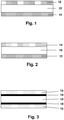
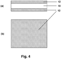
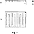
- FIGs 1 to 5 Possible arrangements of such contacted hot melt adhesive tapes are in the Figures 1 to 5 shown.
- the electrically heatable hot melt adhesive 10 is contacted on both sides and over the entire area with a metal foil 12, in particular an aluminum or copper foil.
- the hotmelt adhesive 10 is also in full contact on one side with a metal foil 12 and in part on the other side with a metal net 14.
- Figure 3 shows Figure 3 a product structure in which the hot-melt adhesive 10 is contacted on both sides with a metallized plastic film, 16 each denoting the plastic film and 18 its metal coating.
- the contacts can extend over the entire surface of the entire adhesive tape on both sides or only partially cover the surface on one or both sides, in particular in the form of lines, dots, grids, combs or other geometric shapes. In the former case, there is a current flow transverse to the surface area of the heatable hot melt adhesive (z direction), while in the second case there is exclusively or additionally a current flow within the area of the heatable hot melt adhesive material (xy direction).
- the Figures 4 and 5 illustrate such designs by way of example and without wishing to restrict the invention unnecessarily.
- 10 heatable hotmelt adhesive
- 12 metal foil
- 20 electrode structure
- the hot-melt adhesive sheet according to the invention comprises a layer of a pressure-sensitive adhesive.
- a pressure-sensitive adhesive This can be applied from solution, dispersion or melt to the hot-melt sticky fabric according to the invention or laminated.
- the latter then acts as a backing material for the PSA, so that there is a PSA tape which is pressure-sensitive on one side and hot-melt on the other, but advantageously on a separate backing material (such as in EP 1111021 B1 shown) waived.
- the structure of such an advantageous adhesive tape with a layer of PSA shows Figure 17 ,
- Embodiments of the fabric according to the invention can also be realized with a separate carrier material.
- the carrier material has a high thermal conductivity, in particular of at least 0.5 W / m • K, very particularly preferably of more than 1 W / m • K.
- Particularly preferred materials are polymers filled with thermally conductive fillers, such as boron nitride or aluminum oxide.
- the structure of such an advantageous adhesive tape with a carrier material shows Figure 18 ,
- PSAs All the masses known to the person skilled in the art can be used as PSAs, advantageously those based on acrylic acid and / or methacrylic acid and / or based on esters of the aforementioned compounds or those based on hydrogenated natural or synthetic rubbers, since these are particularly stable to aging and thus withstand repeated heating processes of the fabric according to the invention for a long time.
- PSAs are particularly advantageously used which themselves have a high thermal conductivity, in particular of at least 0.5 W / m • K, very particularly preferably of more than 1 W / m • K.
- Particularly preferred materials are with thermally conductive fillers, e.g. Boron nitride or aluminum oxide, filled PSAs.
- the PSA can be covered with a separating covering material.
- a cover material such.
- film materials here are PP (polypropylene), BOPP (biaxially oriented PP), MOPP (monoaxially oriented PP), PET (polyethylene terephthalate), PVC (polyvinyl chloride), PUR (polyurethane), PE (polyethylene), PE / EVA (polyethylene) / Ethylene vinyl acetate copolymers) and EPDM (ethene / propylene-diene terpolymers).
- Release papers glassine papers, kraft papers, polyolefinically coated papers
- the structure of such an advantageous adhesive tape with a covering material shows Figure 19 ,
- Covering materials are particularly advantageously used which themselves have a high thermal conductivity, in particular of at least 0.5 W / m • K, very particularly preferably of more than 1 W / m • K.
- Particularly preferred materials are with thermally conductive fillers, e.g. Boron nitride or aluminum oxide, filled polymers.
- the heat required for melting the hot-melt adhesive can be better introduced through particularly thermally conductive PSAs, backing and / or covering materials, which is e.g. leads to shorter cycle times in the application.
- the hot melt, heatable layer is constructed from several layers of the same or similar materials. In particular in the case of heating by electrical resistance in the z direction, possible short circuits due to filler agglomerates are avoided.
- the heatable fabric is equipped with a mechanism which, when the fabric is heated for the first time, leads to an increase in cohesion of the hot-melt, heatable layer and / or a further hot-melt adhesive or pressure-sensitive adhesive layer.
- This could, for example, be an increase in the crosslinking density through a thermally initiated postcrosslinking, which is initiated in particular by the heating of the fabric itself.
- Such a flat structure is advantageously used in such a way that the bond is first produced with at least one substrate, then the first heating is carried out and the bond is thus solidified.
- the fabric according to the invention has a high heating capacity and is suitable for use as a hot-melt adhesive tape which, in addition to bonding, also fulfills a heating function, for example for bonding heated mirrors.
- the invention relates to the use of the above-described flat structures for bonding substrates in the automotive industry, furthermore also to the use for heating substrates bonded to such flat structures, in particular in the automotive industry.
- the heating of the substrate is brought about by heating the flat structure, the flat structure being applied to at least one surface which is equipped with at least one electrical contact, the surface in particular being one of the glued substrates itself (but not have to be).
- a 200 ⁇ m thick strip of the fabric according to the invention was sealed onto an untreated polyester film (Mitsubishi Hostaphan) using a heating press under vacuum at a temperature of 140 ° C.
- a 20 mm wide strip was cut out of it, and after conditioning in the room climate for 24 h, the heating foil was again removed from the polyester support subtracted and the force measured. Neither heating foil nor polyester foil was supported or fixed, so that a T-shaped peeling occurred.
- the measurement results are given in N / cm and are averaged from three measurements. All measurements were carried out at room temperature under air-conditioned conditions.
- the temperature increase after the application of electrical voltage was measured.
- the temperature was measured using a Pt100 thermal sensor.
- a 200 ⁇ m thick film of the heatable hot melt adhesive is provided on both sides with a 40 x 80 mm 2 and 50 ⁇ m thick copper foil (hot laminated) and a direct voltage of 12.8 volts is applied to these electrodes via a transformer.
- the upper side was positive, the lower side was negatively charged.
- the temperature was measured directly on the surface of the copper foil after 600 seconds and stated in ° C.
- the hot melt, heatable carrier material became analogous with a comb-shaped conductor structure, which was on a PET carrier material Figure 5 contacted on one side (hot-laminated) and applied on the other side to a glass plate using a 75 ⁇ m thick pressure-sensitive adhesive film (resin-modified acrylate pressure-sensitive adhesive).
- the area of the electrode was 180 cm 2 .
- a DC voltage of 12.8 volts was applied to this flexible circuit board via a transformer. The temperature was measured directly on the surface of the copper foil after 600 seconds and stated in ° C.
- thermoplastics were compounded with the conductive fillers using a Haake Rheomix type kneader. A temperature of 140 ° C. and a speed of 120 min -1 were used over a period of 45 min.
- Sheet materials with a thickness of 200 ⁇ m were produced from the polymer compounds using a vacuum press.
- Table 1 Mixtures of the carrier materials produced Example no. polymer polymer type filler type Proportion of filler [% by weight] 1 ExxonMobil Escorene Ultra FL 00014 EVA, 14% VA Soot Degussa Printex XE2 10 2 ExxonMobil Escorene Ultra FL 00014 EVA Hyperion Catalysis MB 2525-00 (EVA masterbatch with 25% carbon nanotubes) 20 3 ExxonMobil Escorene Ultra FL 00014 EVA 14% VA Graphite Timcal Timrex KS6 36 4 ExxonMobil Escorene Ultra FL 00014 EVA, 14% VA Soot Degussa Printex XE2 15 5 ExxonMobil Escorene Ultra FL 00014 EVA 14% VA Graphite Timcal Timrex KS6 45 6 Dow Primacor 3460 EAA Carbon black Printex XE2 16 counterexamples 7 Basell Hostalen HS GC 7260 F2 HD
- Example 1 The solvent was removed from the PSA prepared for Example 9. The further production of the sample was carried out as described above. This pattern was then made according to Example 1 WO 2004/081136 cross-linked by electron radiation. The dose was 50 kGy at an acceleration voltage of 220 kV.
- the values shown in Table 2 make it clear that Examples 1 to 6 have good hot-melt adhesive properties.
- the adhesive strength can be controlled by the amount and type of filler additive and by the monomer / comonomer composition. The adhesive strength drops due to high proportions of the filling material.
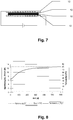
- Test B was carried out to determine the heatability and the PTC effect. Since the piping was carried out in the z direction through the 200 ⁇ m thick fabric, a low filler content was sufficient to produce sufficient conductivity, so that only samples 1 to 3 were tested. The conductivity of the other samples was too high, so that the voltage was reduced due to the current limitation of the power supplies.
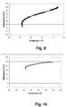
- Figure 8 shows the current, voltage and temperature curve in test B for sample 1, from which the resistance / temperature curve was calculated in Figure 9 that depicted the PTC effect.
- Figure 10 shows such a PTC curve for pattern 2, Figure 11 for pattern 3.
- Test C was also carried out to determine the heatability and the PTC effect.
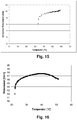
- the more conductive patterns 4, 5 and 6 were used because the distance between the conductor tracks was 1.5 mm.
- Figure 12 shows the current, voltage and temperature curve in test C for sample 4, from which the resistance / temperature curve in was calculated Figure 13 that depicted the PTC effect.
- Figure 14 shows such a PTC curve for pattern 5 and Figure 15 for pattern 6.
- a PSC with PTC effect was examined using test B (sample 9).
- Such PSAs are in WO 2004/081136 A1 described.
- the investigation shows that the PTC effect, which can be determined in the temperature range from 22 to about 40 ° C., is much less pronounced than that in the examples according to the invention.
- the heatable PSA shows an NTC effect (negative temperature coefficient) above 40 ° C, which is disadvantageous in many applications.
- the crosslinking means that the PSA does not melt.
- hotmelt adhesives would not be suitable for use in automotive bonding at least if the adhesive were to be designed as an (electrically) heatable adhesive and this adhesive should be used to heat substrates bonded with such flat structures. In this regard, the person skilled in the art would have had to forego the advantages of gluing with hot-melt adhesives.
- the implementation of the PTC effect has made it possible to offer hot melt adhesives which are self-regulating insofar as they resist the heat-generating moment (here the electrical current) when high values are reached. It can thus be achieved that, due to the system, there is a maximum temperature which the temperature during the heating process cannot exceed. It can thus be avoided that the hotmelt adhesives come into the temperature range of the melting or softening temperature as a result of the heating, the bonding running the risk of deteriorating significantly or even becoming detached.
Landscapes
- Chemical & Material Sciences (AREA)
- Organic Chemistry (AREA)
- Engineering & Computer Science (AREA)
- Microelectronics & Electronic Packaging (AREA)
- Dispersion Chemistry (AREA)
- Ceramic Engineering (AREA)
- Physics & Mathematics (AREA)
- Electromagnetism (AREA)
- Adhesives Or Adhesive Processes (AREA)
- Adhesive Tapes (AREA)
- Surface Heating Bodies (AREA)
- Resistance Heating (AREA)
Description
Die Erfindung betrifft Flächengebilde bestehend aus zumindest einer Schicht Heißschmelzkleber sowie deren Verwendung.The invention relates to fabrics consisting of at least one layer of hot-melt adhesive and the use thereof.
In der Automobilindustrie werden vermehrt elektrisch heizbare Außenspiegel eingesetzt. Auch sind Sitzheizungen immer mehr verbreitet. Um bei derartigen Anwendungen die gewünschte Beheizung zu erreichen, werden im einfachsten Fall Widerstandsdrähte planar verlegt. Die Heizleistung ist hierbei konstant und wird über einen externen Mechanismus gesteuert. In den letzten Jahren hat sich die Verwendung so genannter PTC-Elemente (PTC für "positive temperature coefficient") durchgesetzt.Electrically heated exterior mirrors are increasingly being used in the automotive industry. Seat heaters are also becoming increasingly common. In order to achieve the desired heating in such applications, resistance wires are laid planar in the simplest case. The heating power is constant and is controlled by an external mechanism. In recent years, the use of so-called PTC elements (PTC for "positive temperature coefficient") has become established.
Den PTC-Effekt weisen stromleitende Materialien auf, die bei tieferen Temperaturen den Strom besser leiten können als bei hohen. Derartige Materialien werden auch Kaltleiter genannt; die Materialien verhalten sich entsprechend kaltleitend.The PTC effect is exhibited by current-conducting materials that can conduct electricity better at lower temperatures than at high ones. Such materials are also called PTC thermistors; the materials behave accordingly cold conducting.
So werden etwa für Automobilaußenspiegel beispielsweise mit Aluminium-Leiterbahnen kontaktiertierte PTC-Elemente verklebt. PTC-Elemente sind Elemente, die einem hohen Strom einen Widerstand entgegenstellen. Durch Anlegen einer bestimmten Stromstärke heizt sich das PTC-Element auf, und die Wärme wird über ein doppelseitiges Haftklebeband auf die Glasoberfläche des Spiegels übertragen. Durch den PTC-Effekt wird die erreichte Temperatur begrenzt, da mit zunehmender Temperatur der Widerstand des Heizelements steigt und somit der Stromfluss verringert wird. Auf diese Weise lassen sich Temperaturen von 45 bis 80 °C auf der Oberfläche erzielen. Als PTC-Materialien werden in der Regel rußgefüllte, teilkristalline Thermoplaste, z.B. Polyethylen, Polyvinylidenfluorid, Hexafluorpropylen oder Tetrafluorethylen, verwendet. Der Stand der Technik ist in
Zur Befestigung des PTC-Elements an der Spiegelplatte werden in der Regel Haftklebebänder eingesetzt. Neben einer möglichst hohen thermischen Leitfähigkeit werden an das die Wärme vom PTC-Element zur Spiegeloberfläche transportierende Haftklebeband noch besondere Anforderungen im Hinblick auf Wärmescherfestigkeit bei erhöhten Temperaturen, Witterungsbeständigkeit und Haftklebrigkeit bei tiefen Temperaturen gestellt.Pressure-sensitive adhesive tapes are generally used to attach the PTC element to the mirror plate. In addition to the highest possible thermal conductivity, the pressure-sensitive adhesive tape transporting the heat from the PTC element to the mirror surface also has to meet special requirements with regard to thermal shear strength at elevated temperatures, weather resistance and pressure-sensitive tack at low temperatures.
Das bestehende Konzept funktioniert gut, erfordert aber einen relativ komplizierten Aufbau, da die PTC-Elemente nicht nur mit dem Glas des Spiegels verklebt werden müssen, sondern auch mit der Trägerplatte des Spiegels, die in vielen Fällen aus dem Kunststoff Acrylnitril/Butadien/Styrol (ABS) besteht. Die Verklebung dieser unterschiedlichen Materialien stellt ebenfalls besondere Anforderungen an das Klebeband.The existing concept works well, but requires a relatively complicated structure, since the PTC elements not only have to be glued to the glass of the mirror, but also to the support plate of the mirror, which in many cases is made of acrylic nitrile / butadiene / styrene ( ABS). The bonding of these different materials also places special demands on the adhesive tape.
Bekannt sind aus
Auch die D3 beschreibt eine Schicht einer erwärmbaren Klebmasse, die einen PTC-Effekt zeigt. Auch hierbei handelt es sich um eine Haftklebemasse, nicht jedoch um eine Heißschmelzklebmasse.D3 also describes a layer of a heatable adhesive that shows a PTC effect. This is also a pressure sensitive adhesive, but not a hot melt adhesive.
Für eine Vereinfachung des Herstellprozesses von beheizbaren Spiegeln besteht somit der Bedarf für ein verbessertes erwärmbares, selbstregulierendes Klebeband, welches die Trägerplatte mit dem Spiegel verklebt und zudem z. B. durch elektrischen Strom oder einen anderen physikalischen Prozess in sich selbst Wärme erzeugt.To simplify the manufacturing process of heated mirrors, there is therefore a need for an improved, heatable, self-regulating adhesive tape, which bonds the carrier plate to the mirror and also, for. B. generates heat in itself by electric current or another physical process.
Gelöst wird die Aufgabe überraschend und für den Fachmann in nicht vorhersehbarer Weise durch ein Flächengebilde gemäß Patentanspruch 1, umfassend mindestens eine Schicht, innerhalb derer Wärme erzeugt werden kann, wobei diese Schicht heißschmelzklebrig und kaltleitend ist, also den PTC-Effekt aufweist.The problem is solved surprisingly and for the person skilled in the art in an unpredictable manner by a flat structure according to claim 1, comprising at least one layer within which heat can be generated, this layer being hot-melt-tacky and cold-conducting, ie having the PTC effect.
Die Unteransprüche betreffen bevorzugte Weiterentwicklungen dieses Flächengebildes sowie dessen Verwendung.The subclaims relate to preferred further developments of this fabric and its use.
Bevorzugt wird die Wärme innerhalb der heißschmelzklebrigen Schicht durch den elektrischen Widerstand erzeugt. Erfindungsgemäß können solche Flächengebilde einmalig oder mehrfach eingesetzt werden, ebenfalls kann der Wärmeerzeugungsprozess einmalig oder reproduzierbar durchführbar sein.The heat is preferably generated within the hotmelt adhesive layer by the electrical resistance. According to the invention, such fabrics can be used once or several times, and the heat generation process can also be carried out once or in a reproducible manner.
Die Wärmeerzeugung in der heißschmelzklebrigen Schicht wird durch den PTC-Effekt begrenzt, so dass die Schicht sich bezüglich der Wärmeentwicklung selbstregulierend verhält, insbesondere im Hinblick auf einen nicht zu überschreitenden Temperaturhöchstwert. Eine Überhitzung des Flächengebildes soll somit vermieden werden.The heat generation in the hotmelt-adhesive layer is limited by the PTC effect, so that the layer behaves in a self-regulating manner with regard to the heat development, in particular with regard to a maximum temperature value which should not be exceeded. Overheating of the fabric should thus be avoided.
In einer einfachen Ausführungsform besteht das Flächengebilde aus einer singulären Lage einer wärmeerzeugenden Heißschmelzklebemasse, welche zum Beispiel Spiegel und Trägerplatte verbindet. Die für eine widerstandselektrische Erwärmung notwendige Kontaktierung ist dann in einem separaten Element, welches auch der Spiegel oder die Spiegelträgerplatte sein kann, untergebracht.In a simple embodiment, the flat structure consists of a singular layer of a heat-generating hotmelt adhesive which, for example, connects the mirror and the carrier plate. The contacting necessary for electrical resistance heating is then accommodated in a separate element, which can also be the mirror or the mirror support plate.
In einer zweiten, bevorzugten Ausführungsform ist die Kontaktierung integraler Bestandteil des Flächengebildes.In a second, preferred embodiment, the contacting is an integral part of the fabric.
Ein wichtiger Bestandteil des erfindungsgemäßen Flächengebildes (Heißschmelzklebebands) ist die erwärmbare Heißschmelzklebemasse.An important component of the fabric (hot-melt adhesive tape) according to the invention is the heatable hot-melt adhesive.
Heißschmelzklebrig im Sinne der vorliegenden Erfindung ist ein erfindungsgemäßes Flächengebilde, wenn nach der schmelzeförmigen Applikation auf den Haftgrund und anschließendem Abkühlen die Klebkraft bei Raumtemperatur nach ASTM D 3330-04 (bei einer Abzugsgeschwindigkeit von 300 mm/min auf dem zu verklebenden Haftgrund) größer ist als 1 N/cm, bevorzugt größer ist als 3 N/cm, besonders bevorzugt größer ist als 5 N/cm.A hot melt adhesive in the sense of the present invention is a fabric according to the invention if, after the melt-like application to the adhesive base and subsequent cooling, the adhesive strength at room temperature according to ASTM D 3330-04 (at a peeling speed of 300 mm / min on the adhesive base to be bonded) is greater than 1 N / cm, preferably greater than 3 N / cm, particularly preferably greater than 5 N / cm.
Vorteilhaft lassen sich solche Heißschmelzklebemassen einsetzen, welche
- (a) mindestens eine Klebstoffkomponente und
- (b) mindestes ein elektrisch leitfähiges Material ("Füllmaterial")
- (a) at least one adhesive component and
- (b) at least one electrically conductive material ("filler material")
Im Falle einer somit elektrisch erwärmbaren Heißschmelzklebemasse ist der Zusatz mindestens eines elektrisch leitfähigen Füllmaterials, welches unter Strombeaufschlagung Wärme entwickelt, vorteilhaft. In einer bevorzugten Ausführungsform können Graphite oder Ruße eingesetzt werden. In einer weiter bevorzugten Ausführung ist dieser Füllstoff nanoskalig, d.h. er besitzt in mindestens einer Raumdimension eine Ausdehnung von nicht mehr als 500 nm, bevorzugt nicht mehr als 200 nm, besonders bevorzugt nicht mehr als 50 nm. In einer sehr bevorzugten Ausführungsform wird Leitruß (beispielsweise Printex® XE der Fa. Degussa) eingesetzt. In einer weiter sehr bevorzugten Ausführungsform werden Kohlenstoff-Nanoröhren (Carbon-Nanotubes; z.B. der Fa. Ahwahnee oder Carbon-Nanotube-Masterbatches der Fa. Hyperion Catalysis) und/oder Kohlenstoff-Nanofasern (Carbon-Nanofibres) eingesetzt. Vorteilhaft ist hierbei der geringe Anteil an Füllstoff, der für die Erwärmung benötigt wird, so dass die mechanischen Eigenschaften des Heißschmelzklebers nur wenig beeinflusst werden.In the case of a hot-melt adhesive which can thus be heated electrically, the addition of at least one electrically conductive filler material which develops heat when current is applied is advantageous. In a preferred embodiment, graphite or carbon black can be used. In a further preferred embodiment, this filler is nanoscale, i.e. in at least one spatial dimension it has an extent of not more than 500 nm, preferably not more than 200 nm, particularly preferably not more than 50 nm. In a very preferred embodiment, conductive carbon black (for example Printex® XE from Degussa) is used. In a further very preferred embodiment, carbon nanotubes (carbon nanotubes; e.g. from Ahwahnee or carbon nanotube masterbatches from Hyperion Catalysis) and / or carbon nanofibers (carbon nanofibers) are used. The low proportion of filler that is required for heating is advantageous here, so that the mechanical properties of the hot-melt adhesive are influenced only slightly.
Die Ausprägung des Effektes der elektrischen Erwärmbarkeit der Heißschmelzklebemasse kann durch den Füllgrad, das heißt den Massenanteil, des Füllmaterials in der Heißschmelzklebemasse, bestimmt werden. Der Füllgrad beträgt vorteilhaft zwischen 1 und 60 Gew.-%. Sehr bevorzugt werden zwischen 5 und 50 Gew.-% Füllmaterial eingesetzt.The form of the effect of the electrical heatability of the hot-melt adhesive can be determined by the degree of filling, that is to say the mass fraction, of the filler material in the hot-melt adhesive. The degree of filling is advantageously between 1 and 60% by weight. Between 5 and 50% by weight of filler material is very preferably used.
Die Leitfähigkeit und somit auch die erzielbare Temperatur und Aufheizrate ist unter anderem abhängig vom Füllgrad. Durch Anhebung des Füllgrades lassen sich höhere Leitfähigkeiten und gegebenenfalls auch höhere Temperaturen erreichen. Weiterhin ist die elektrische Leitfähigkeit und somit die Erwärmbarkeit der Heißschmelzklebemasse auch vom Basispolymer der Klebstoffkomponente abhängig.The conductivity and thus also the achievable temperature and heating rate depend, among other things, on the degree of filling. By increasing the filling level, higher conductivities and possibly also higher temperatures can be achieved. Furthermore, the electrical conductivity and thus the heatability of the hotmelt adhesive is also dependent on the base polymer of the adhesive component.
Eine weitere Verbesserung des Trägermaterials kann durch die Zugabe von mindestens einem Füllstoff mit hoher Wärmekapazität, insbesondere mit einer Wärmekapazität von mehr als 0,7 J/gK, erreicht werden. Dies führt durch die Pufferfunktion zu einer Vergleichmäßigung des Aufheizverhaltens und einer verlängerten Abgabe von Wärme nach Beendigung des aktiven Wärmeerzeugungsprozesses. Füllstoffe mit hoher Wärmekapazität, die erfindungsgemäß vorteilhaft eingesetzt werden können, sind z.B. Aluminium, Beryllium, Bor, Calcium, Eisen, Graphit, Kalium, Kupfer, Magnesium, Phosphor oder Verbindungen der vorgenannten Stoffe, insbesondere Aluminiumoxid und -chlorid, Calciumcarbonat, Calciumclorid, Kupfersulfat, Magnetit, Haematit, Magnesiumcarbonat und -clorid, Phosphorchlorid, Phosphoroxid.A further improvement of the carrier material can be achieved by adding at least one filler with a high heat capacity, in particular with a heat capacity of more than 0.7 J / gK. Due to the buffer function, this leads to a more even heating behavior and an extended release of heat after the active heat generation process has ended. Fillers with a high heat capacity which can be used advantageously according to the invention are, for example, aluminum, beryllium, boron, calcium, iron, graphite, potassium, copper, magnesium, phosphorus or compounds of the aforementioned substances, in particular aluminum oxide and -chloride, calcium carbonate, calcium chloride, copper sulfate, magnetite, haematite, magnesium carbonate and -chloride, phosphorus chloride, phosphorus oxide.
Als Klebstoffkomponente der elektrisch beheizbaren Heißschmelzklebemassen können hervorragend alle Polymere mit geeigneten heißschmelzklebenden Eigenschaften eingesetzt werden, die zusammen mit dem elektrisch leitenden Fülllmaterial einen PTC-Effekt aufweisen, sich also kaltleitend verhalten. Bevorzugt werden mehrphasige Systeme verwendet, insbesondere solche, bei denen zumindest eine Phase im Temperatur-Bereich des Auftretens des PTC-Effekts durch die Erwärmung eine Volumenausdehnung erfährt, die nach allgemein anerkannter wissenschaftlicher Erklärung zumindest teilweise den PTC-Effekt verursacht (s.
Besonders bevorzugt werden teilkristalline Polymere oder Block-Copolymere eingesetzt. Als teilkristalline Systeme können sowohl einphasige als auch mehrphasige Systeme eingesetzt werden. Bevorzugt enthält die Heißschmelzklebemasse mindestens 30 Gew.-% teilkristalliner Polymere, noch besser ist ein Anteil an teilkristallinen Polymeren von mindestens 50 Gew.-% in der Heißschmelzklebemasse. Es hat sich herausgestellt, dass die Eignung zur Erzielung des PTC-Effektes sich mit dem Anteil an teilkristallinen Systemen - verglichen mit Haftklebemassen, die mit zunehmendem teilkristallinen Anteil ihre haftklebrigen Eigenschaften verlieren und daher nur geringere Anteile an teilkristallinen Systemen aufweisen - überraschend stark verbessert. Heißschmelzklebemassen sind daher für die Anwendung des PTC-Effektes über die Erwartungen hinaus gut geeignet.Semi-crystalline polymers or block copolymers are particularly preferably used. Both single-phase and multi-phase systems can be used as partially crystalline systems. The hot-melt adhesive preferably contains at least 30% by weight of partially crystalline polymers, and a proportion of partially-crystalline polymers of at least 50% by weight in the hot-melt adhesive is even better. It has been found that the suitability for achieving the PTC effect is surprisingly greatly improved with the proportion of partially crystalline systems - compared to PSAs which lose their pressure-sensitive properties with increasing proportion of the partially crystalline component and therefore have only lower proportions of partially crystalline systems. Hot melt adhesives are therefore well suited for the application of the PTC effect beyond expectations.
Als im erfinderischen Sinne besonders vorteilhaft haben sich teilkristalline Polymere oder Block-Copolymere herausgestellt, die zu 100 % in der Klebemasse enthalten sind oder die nahezu zu 100 % in der Klebemasse enthalten sind.Semi-crystalline polymers or block copolymers which are 100% contained in the adhesive or which are almost 100% contained in the adhesive have been found to be particularly advantageous in the inventive sense.
Insbesondere bevorzugt sind werden solche teilkristallinen Polymere eingesetzt, bei denen der Kristallinitätsgrad, welcher mit der Differential-Scannig-Calorimetry (DSC) ermittelt wird, bevorzugt mehr als 20 %, besonders bevorzugt mehr als 40 % beträgt.Particularly preferred are those partially crystalline polymers in which the degree of crystallinity, which is determined using differential scanning calorimetry (DSC), is preferably more than 20%, particularly preferably more than 40%.
Ganz besonders bevorzugt werden im Bereich der teilkristallinen Thermoplaste Polyolefine (z.B. Polyethylen niedriger Dichte) oder Copolymere von Polyolefinen (z.B. Ethylen-Vinylacetat (EVA), Ethylen-Acrylsäure (EAA), Ethylen-Methacrylsäure (EMAA), Ethylen-Ethylacrylat, Ethylen-Butylacrylat), lonomere, Polyamide und/oder deren Copolymere eingesetzt. Diese weisen neben ausreichendem PTC-Effekt auch besonders gute Heißschmelzklebeeigenschaften auf.Polyolefins (eg low-density polyethylene) or copolymers of polyolefins (eg Ethylene vinyl acetate (EVA), ethylene acrylic acid (EAA), ethylene methacrylic acid (EMAA), ethylene ethyl acrylate, ethylene butyl acrylate), ionomers, polyamides and / or their copolymers. In addition to a sufficient PTC effect, these also have particularly good hot-melt adhesive properties.
Weiterhin bevorzugt werden im Bereich der teilkristallinen Thermoplaste säuremodifizierte (z.B. mit Maleinsäure oder Maleinsäureanhydrid) Polyolefine oder deren Copolymere, da diese besonders gut mit den leitfähigen Füllstoffen (z.B. Ruß oder Kohlenstoffnanoröhrchen) verträglich sind und somit leichter homogene Dispersionen des Füllstoffs in der Polymermatrix hergestellt werden können.Also preferred in the field of semi-crystalline thermoplastics are acid-modified (e.g. with maleic acid or maleic anhydride) polyolefins or their copolymers, since these are particularly well compatible with the conductive fillers (e.g. carbon black or carbon nanotubes) and thus it is easier to produce homogeneous dispersions of the filler in the polymer matrix ,
Ganz besonders bevorzugt werden als Block-Copolymere Styrol-Block-Copolymere, wie z.B SBS (Styrol/Butadien/Styrol-Blockcopolymere), SIS (Styrol/Isopren/Styrol-Blockcopolymere), SEBS (Styrol-Ethlyen-Butylen-Styrol-Blockcopolymere) oder SEPS (Styrol-Ethylen-Propylen-Styrol-Blockcopolymere) eingesetzt.Styrene block copolymers such as SBS (styrene / butadiene / styrene block copolymers), SIS (styrene / isoprene / styrene block copolymers), SEBS (styrene-ethylene-butylene-styrene block copolymers) are very particularly preferred as block copolymers. or SEPS (styrene-ethylene-propylene-styrene block copolymers) are used.
Zur Optimierung der klebtechnischen Eigenschaften können den erfinderischen Heißschmelzklebemassen vorteilhaft Harze beigemischt werden. Als zuzusetzende klebrigmachende Harze sind ausnahmslos alle vorbekannten und in der Literatur beschriebenen Klebharze einsetzbar. Genannt seien stellvertretend die Pinen-, Inden- und Kolophoniumharze, deren disproportionierte, hydrierte, polymerisierte, veresterte Derivate und Salze, die aliphatischen und aromatischen Kohlenwasserstoffharze, Terpenharze und Terpenphenolharze sowie C5- bis C9- sowie andere Kohlenwasserstoffharze. Beliebige Kombinationen dieser und weiterer Harze können eingesetzt werden, um die Eigenschaften der resultierenden Klebmasse wunschgemäß einzustellen. Im Allgemeinen lassen sich alle mit dem entsprechenden Thermoplast kompatiblen (löslichen) Harze einsetzen, insbesondere sei verwiesen auf alle aliphatischen, aromatischen, alkylaromatischen Kohlenwasserstoffharze, Kohlenwasserstoffharze auf Basis reiner Monomere, hydrierte Kohlenwasserstoffharze, funktionelle Kohlenwasserstoffharze sowie Naturharze. In einer bevorzugten Auslegung werden Harze eingesetzt, die die elektrische Leitfähigkeit und die Erwärmbarkeit - auch über einen längeren Zeitraum - nicht vermindern.To optimize the technical adhesive properties, resins can advantageously be admixed with the inventive hotmelt adhesives. All of the previously known adhesive resins described in the literature can be used as tackifying resins to be added. Representative are the pinene, indene and rosin resins, their disproportionated, hydrogenated, polymerized, esterified derivatives and salts, the aliphatic and aromatic hydrocarbon resins, terpene resins and terpene phenolic resins as well as C 5 - to C 9 - and other hydrocarbon resins. Any combination of these and other resins can be used to adjust the properties of the resulting adhesive as desired. In general, all (soluble) resins compatible with the corresponding thermoplastic can be used, in particular reference is made to all aliphatic, aromatic, alkylaromatic hydrocarbon resins, hydrocarbon resins based on pure monomers, hydrogenated hydrocarbon resins, functional hydrocarbon resins and natural resins. In a preferred embodiment, resins are used which do not reduce the electrical conductivity and the heatability - even over a longer period of time.
Bevorzugt werden die für die erfinderischen Flächengebilde eingesetzten Heißschmelzklebemassen vernetzt, wobei hohe Vernetzungsgrade angestrebt werden, die insbesondere auch den PTC-Effekt unterstützen (s.
Weiterhin ist Bestandteil der Erfindung das Verfahren, bei welchem eine Variation der elektrischen Leitfähigkeit und somit der thermischen Erwärmung über den Vernetzungsgrad bewirkt wird. Durch Erhöhung der ES-Dosis (und damit auch des Vernetzungsgrades) lässt sich die elektrische Leitfähigkeit erhöhen und bei gleichem Strom erhöht sich die Temperatur der Heißschmelzklebemasse. Ebenso lässt sich über den Vernetzungsgrad der PTC-Effekt einstellen.Furthermore, part of the invention is the method in which a variation in the electrical conductivity and thus the thermal heating is effected via the degree of crosslinking. The electrical conductivity can be increased by increasing the ES dose (and thus also the degree of crosslinking) and the temperature of the hotmelt adhesive increases with the same current. The degree of crosslinking can also be used to set the PTC effect.
Zur Verringerung der erforderlichen Dosis können der Heißschmelzklebemasse Vernetzer und/oder Promotoren zur Vernetzung beigemischt werden, insbesondere durch Elektronenstrahlen oder thermisch anregbare Vernetzer und/oder Promotoren. Geeignete Vernetzer für die Elektronenstrahlvernetzung sind z.B. bi- oder multifunktionelle Acrylate oder Methacrylate, aber auch Triallylcyanurate und -isocyanurate. In einer weiteren bevorzugten Auslegung werden die Heißschmelzklebemassen mit thermisch aktivierbaren Vernetzern vernetzt. Hierzu werden bevorzugt bi- oder multifunktionelle Epoxide, bi- oder multifunktionelle Hydroxide sowie bi- oder multifunktionelle Isocyanate oder Silane beigemischt.To reduce the required dose, crosslinking agents and / or promoters for crosslinking can be added to the hotmelt adhesive, in particular by means of electron beams or thermally excitable crosslinkers and / or promoters. Suitable crosslinkers for electron beam crosslinking are, for example, bi- or multifunctional acrylates or methacrylates, but also triallyl cyanurates and isocyanurates. In a further preferred embodiment, the hotmelt adhesives are crosslinked with thermally activatable crosslinkers. For this purpose, preference is given to bi- or multifunctional Epoxies, bi- or multifunctional hydroxides and bi- or multifunctional isocyanates or silanes are added.
Weiterhin können der Heißschmelzklebemasse vorteilhaft Weichmacher (Plastifizierungsmittel) zur Verbesserung der Klebfähigkeit zugesetzt sein.Furthermore, plasticizers (plasticizers) can advantageously be added to the hotmelt adhesive in order to improve the adhesiveness.
Vorteilhaft ist auch der Zusatz polymerer oder anorganischer Füllstoffe, die mit ihrem Aufschmelzen während der Erwärmung den PTC-Effekt unterstützen. Dies können z. B. hochkristalline Polyolefinwachse oder Ionische Flüssigkeiten (niedrigschmelzende Metallsalze) sein. Durch die Wahl des Schmelzpunktes der Füllstoffe kann zudem die Temperatur, bei der der PTC-Effekt auftritt, eingestellt werden.It is also advantageous to add polymeric or inorganic fillers which, when melted, support the PTC effect during heating. This can e.g. B. highly crystalline polyolefin waxes or ionic liquids (low-melting metal salts). The temperature at which the PTC effect occurs can also be set by choosing the melting point of the fillers.
Die elektrisch leitfähigen Füllmaterialien können den Monomeren vor der Polymerisation und/oder während der Polymerisation und/oder den Polymeren nach Beendigung der Polymerisation beigemischt werden. Vorzugsweise wird das Füllmaterial nach der Polymerisation zu einer Schmelze der mindestens einen Klebstoffkomponente kompoundiert.The electrically conductive filler materials can be added to the monomers before the polymerization and / or during the polymerization and / or to the polymers after the end of the polymerization. The filling material is preferably compounded into a melt of the at least one adhesive component after the polymerization.
Für die Beschichtung aus der Schmelze als Hotmelt-System wird bevorzugt das elektrisch leitfähige Füllmaterial zu der Schmelze kompoundiert. Hierbei ist eine homogene Einarbeitung im erfindungsgemäßen Sinne wünschenswert. Homogene Verteilungen des Füllmaterials in der Heißschmelzklebemasse werden bevorzugt durch Kompoundierung in Doppelschneckenextrudern oder Planetwalzenextrudern erreicht. Vorteil dieses Prozesses ist die nur sehr kurzfristige Kontaminierung des Herstellprozesses mit dem Füllmaterial sowie die Vermeidung von Lösemitteln.For the coating from the melt as a hot melt system, the electrically conductive filler material is preferably compounded into the melt. Homogeneous incorporation in the sense of the invention is desirable here. Homogeneous distributions of the filling material in the hot melt adhesive are preferably achieved by compounding in twin-screw extruders or planetary roller extruders. The advantage of this process is the very short-term contamination of the manufacturing process with the filling material and the avoidance of solvents.
Das erfindungsgemäße Flächengebilde kann mit den geläufigen Verfahren zur Herstellung polymerer Folien nach dem Stand der Technik hergestellt werden. Dazu zählen z.B. die Flachfolienextrusion, die Blasfolienextrusion, das Kalanderverfahren, die Beschichtung aus einer Lösung oder einer monomeren oder einer präpolymeren Vorstufe des Polymeren.The sheet-like structure according to the invention can be produced using the current methods for producing polymer films according to the prior art. These include, for example, flat film extrusion, blown film extrusion, the calendering process, coating from a solution or a monomeric or a prepolymeric precursor of the polymer.
Das Flächengebilde kann vorteilhaft eine Dicke bis 1000 µm aufweisen. Gemäß einer besonders vorteilhaften Ausführungsform der Erfindung beträgt diese 10 bis 400 µm, ganz besonders 30 bis 200 µm.The fabric can advantageously have a thickness of up to 1000 μm. According to a particularly advantageous embodiment of the invention, this is 10 to 400 μm, very particularly 30 to 200 μm.
Durch den Herstellprozess eingebrachte Orientierungen innerhalb des Polymers (insbesondere die Einbringung anisotroper Eigenschaften bezüglich physikalischer Eigenschaften und/oder bezüglich der Ausrichtung der Makromoleküle) können den PTC-Effekt unterstützen.Orientations introduced by the manufacturing process within the polymer (in particular the introduction of anisotropic properties with regard to physical properties and / or with regard to the alignment of the macromolecules) can support the PTC effect.
Eine vorteilhafte Ausführung der Erfindung betrifft erfindungsgemäße Flächengebilde, insbesondere wie sie in den vorstehenden Textpassagen dargelegt sind, (besonders vorteilhaft in Form elektrisch erwärmbarer Heißschmelzklebebänder), die einen Film einer erwärmbaren Heißschmelzklebemasse und eine elektrisch leitfähige Kontaktierung umfassen.An advantageous embodiment of the invention relates to sheet-like structures according to the invention, in particular as set out in the text passages above (particularly advantageously in the form of electrically heatable hot-melt adhesive tapes), which comprise a film of heatable hot-melt adhesive and an electrically conductive contact.
Vorteilhaft geeignete Kontaktierungen sind Metallfolien, Metallnetze oder metallbeschichtete Kunststofffolien, Papiere oder Vliese.Metal foils, metal nets or metal-coated plastic foils, papers or nonwovens are advantageously suitable contacts.
In einem einfachen Fall wird die erwärmbare Heißschmelzklebemasse mit einem elektrisch leitfähigen Metall kontaktiert. In bevorzugter Weise werden Metalle eingesetzt, die nicht oder nur wenig über längere Zeiträume korrodieren. In sehr bevorzugten Ausführungen wird beispielsweise Kupfer oder Aluminium eingesetzt, wobei aber auch Silber- oder Gold-Kontaktierungen vorgenommen werden können. Dabei kann das Metall z.B. durch galvanische oder Bedampfungsverfahren direkt auf der Heißschmelzklebemasse abgeschieden werden oder in Form einer kontinuierlichen oder durchbrochenen Schicht aufkaschiert werden. Auch die Verwendung eines Leitlacks oder einer leitfähigen Tinte oder Druckfarbe ist möglich.In a simple case, the heatable hot-melt adhesive is contacted with an electrically conductive metal. Metals are preferably used which do not or only slightly corrode over longer periods of time. In very preferred versions, for example, copper or aluminum is used, but silver or gold contacts can also be made. The metal can e.g. are deposited directly on the hot-melt adhesive by galvanic or vapor deposition processes or are laminated on in the form of a continuous or openwork layer. The use of a conductive lacquer or a conductive ink or printing ink is also possible.
Die
- Figur 1:
- Kontaktierung über AI-Folie
- Figur 2:
- Kontaktierung über AI-Folie und Metallnetz
- Figur 3:
- Kontaktierung über metallisierte Folie
- Figur 4:
- Ganzflächig kontaktierte Heißschmelzklebemasse: (a) Querschnitt, (b) Aufsicht
- Figur 5:
- Einseitig mit einer Kammstruktur kontaktierte Klebemasse: (a) Querschnitt, (b) Aufsicht
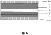
- Figur 6:
- erfindungsgemäßes mehrschichtiges Flächengebilde
- Figur 7:
- erfindungsgemäßes Flächengebilde mit zweilagigem Aufbau der erwärmbaren Heißschmelzklebemasse und flächiger Kontaktierung
- Figure 1:
- Contact via AI foil
- Figure 2:
- Contact via AI foil and metal net
- Figure 3:
- Contacting via metallized foil
- Figure 4:
- Hot melt adhesive contacted over the entire surface: (a) cross section, (b) top view
- Figure 5:
- Adhesive contacted on one side with a comb structure: (a) cross section, (b) top view
- Figure 6:
- multilayer sheet according to the invention
- Figure 7:
- Flat structure according to the invention with a two-layer structure of the heatable hot-melt adhesive and flat contact
Mögliche Anordnungen solcher kontaktierter Heißschmelzklebebänder sind in den
Die Kontaktierungen können sich beidseitig ganzflächig über die gesamte Klebebandoberfläche erstrecken oder die Oberfläche ein oder beidseitig nur partiell, insbesondere in Form von Linien, Punkten, Rastern, Kämmen oder anderen geometrischen Formen, abdecken. Im ersteren Fall ergibt sich ein Stromfluss quer zur Flächenausdehnung der erwärmbaren Heißschmelzklebemasse (z-Richtung), während sich im zweiten Fall ausschließlich oder zusätzlich ein Stromfluss innerhalb der Flächenausdehnung der erwärmbaren Heißschmelzklebemasse ergibt (x-y-Richtung). Die
Es bedeuten: 10 = erwärmbare Heißschmelzklebemasse, 12 = Metallfolie, 20 = ElektrodenstrukturThe meanings are: 10 = heatable hotmelt adhesive, 12 = metal foil, 20 = electrode structure
Weitere vorteilhafte Produktgestaltungen sind realisierbar. Ein besonders vorteilhafter Aufbau des Trägermaterials umfasst neben der erwärmbaren Heißschmelzklebemasse noch weitere Heißschmelzkleber- und/oder Haftkleberschichten und Kontaktierungsschichten sowie abdeckende Materialien (vgl. ein Beispiel eines solchen Flächengebildes in
In einer vorteilhaften Ausführung umfasst das erfindungsgemäße heißschmelzklebrige Flächengebilde eine Schicht einer Haftklebemasse. Diese kann aus Lösung, Dispersion oder Schmelze auf das erfindungsgemäße heißschmelzklebrige Flächengebilde aufgebracht oder zukaschiert werden. Letzteres fungiert dann als Trägermaterial für die Haftklebemasse, so dass sich ein Haftklebeband ergibt, welches einseitig haftklebrig und anderseitig heißschmelzklebrig ist, aber vorteilhafterweise auf ein separates Trägermaterial (wie z.B. in
Ausführungsformen des erfindungsgemäßen Flächengebildes können auch mit einem separaten Trägermaterial verwirklich sein. In diesem Fall ist es besonders vorteilhaft, wenn das Trägermaterial eine hohe Wärmeleitfähigkeit aufweist, insbesondere von mindestens 0,5 W/m•K, ganz besonders bevorzugt von mehr als 1 W/m•K. Besonders bevorzugte Materialien sind mit wärmeleitfähigen Füllstoffen, wie z.B. Bornitrid oder Aluminiumoxid, gefüllte Polymere. Den Aufbau eines solchen vorteilhaften Klebebands mit einem Trägermaterial zeigt
Als Haftklebemassen können alle dem Fachmann bekannten Massen verwendet werden, vorteilhafterweise solche auf Basis von Acrylsäure und/oder Methacrylsäure und/oder auf Basis von Estern der vorgenannten Verbindungen oder eine solche auf Basis von hydrierten Natur- oder Synthesekautschuken, da diese besonders alterungsstabil sind und somit wiederholten Heizprozessen des erfindungsgemäßen Flächengebildes langzeitig standhalten.All the masses known to the person skilled in the art can be used as PSAs, advantageously those based on acrylic acid and / or methacrylic acid and / or based on esters of the aforementioned compounds or those based on hydrogenated natural or synthetic rubbers, since these are particularly stable to aging and thus withstand repeated heating processes of the fabric according to the invention for a long time.
Besonders vorteilhaft werden Haftklebemassen eingesetzt, die selbst eine hohe Wärmeleitfähigkeit aufweisen, insbesondere von mindestens 0,5 W/m•K, ganz besonders bevorzugt von mehr als 1 W/m•K. Besonders bevorzugte Materialien sind mit wärmeleitfähigen Füllstoffen, wie z.B. Bornitrid oder Aluminiumoxid, gefüllte Haftklebemassen.PSAs are particularly advantageously used which themselves have a high thermal conductivity, in particular of at least 0.5 W / m • K, very particularly preferably of more than 1 W / m • K. Particularly preferred materials are with thermally conductive fillers, e.g. Boron nitride or aluminum oxide, filled PSAs.
Zusätzlich kann die Haftklebemasse mit einem trennenden Abdeckmaterial eingedeckt werden. Als Abdeckmaterial eignen sich z. B. alle silikonisierten oder fluorierten Folien mit einer Releasewirkung. Als Folienmaterialien seien hier nur beispielhaft PP (Polypropylen), BOPP (biaxial orientiertes PP), MOPP (monoaxial orientiertes PP), PET (Polyethylenterephthalat), PVC (Polyvinylchlorid), PUR (Polyurethan), PE (Polyeethylen), PE/EVA (Polyethylen/Ethylenvinylacetat-Copolymere) und EPDM (Ethen/Propylen-Dien-Terpolymere) genannt. Weiterhin lassen sich auch Trennpapiere (Glassine Papiere, Kraft Papiere, polyolefinisch beschichtete Papiere) einsetzen. Den Aufbau eines solchen vorteilhaften Klebebands mit einem Abdeckmaterial zeigt
Besonders vorteilhaft werden Abdeckmaterialien eingesetzt, die selbst eine hohe Wärmeleitfähigkeit aufweisen, insbesondere von mindestens 0,5 W/m•K, ganz besonders bevorzugt von mehr als 1 W/m•K. Besonders bevorzugte Materialien sind mit wärmeleitfähigen Füllstoffen, wie z.B. Bornitrid oder Aluminiumoxid, gefüllte Polymere.Covering materials are particularly advantageously used which themselves have a high thermal conductivity, in particular of at least 0.5 W / m • K, very particularly preferably of more than 1 W / m • K. Particularly preferred materials are with thermally conductive fillers, e.g. Boron nitride or aluminum oxide, filled polymers.
Durch besonders wärmeleitfähige Haftklebemassen, Träger- und/oder Abdeckmaterialien kann die zum Aufschmelzen des Heißschmelzklebers erforderliche Energie besser eingebracht werden, was z.B. zu verkürzten Zykluszeiten bei der Applikation führt.The heat required for melting the hot-melt adhesive can be better introduced through particularly thermally conductive PSAs, backing and / or covering materials, which is e.g. leads to shorter cycle times in the application.
In einer bevorzugten Ausführungsform wird die heißschmelzklebrige erwärmbare Schicht aus mehreren Lagen desselben oder ähnlicher Materialien aufgebaut. Insbesondere im Fall der Erwärmung durch elektrischen Widerstand in z-Richtung werden so mögliche Kurzschlüsse durch Füllstoffagglomerate vermieden. In
Es bedeuten: 10 = erwärmbare Heißschmelzklebemasse, 12 = MetallfolieIn a preferred embodiment, the hot melt, heatable layer is constructed from several layers of the same or similar materials. In particular in the case of heating by electrical resistance in the z direction, possible short circuits due to filler agglomerates are avoided. In
It means: 10 = heatable hot melt adhesive, 12 = metal foil
In einer weiteren vorteilhaften Ausführung ist das erwärmbare Flächengebilde mit einem Mechanismus ausgestattet, der bei erstmaliger Erwärmung des Flächengebildes zu einer Kohäsionserhöhung der heißschmelzklebrigen erwärmbaren Schicht und/oder einer weiteren Heißschmelzkleber- oder Haftkleberschicht führt. Dies könnte beispielsweise eine Erhöhung der Vernetzungsdichte durch eine thermisch initiierte Nachvernetzung, die insbesondere durch die Erwärmung des Flächengebildes selbst initiiert wird, sein. Vorteilhafterweise wird eine solches Flächengebilde derart verwendet, dass zunächst die Verklebung mit mindestens einem Substrat hergestellt wird, sodann die erstmalige Erwärmung vorgenommen wird und sich damit eine Verfestigung der Verklebung einstellt.In a further advantageous embodiment, the heatable fabric is equipped with a mechanism which, when the fabric is heated for the first time, leads to an increase in cohesion of the hot-melt, heatable layer and / or a further hot-melt adhesive or pressure-sensitive adhesive layer. This could, for example, be an increase in the crosslinking density through a thermally initiated postcrosslinking, which is initiated in particular by the heating of the fabric itself. Such a flat structure is advantageously used in such a way that the bond is first produced with at least one substrate, then the first heating is carried out and the bond is thus solidified.
Das erfindungsgemäße Flächengebilde weist eine hohe Erwärmungsleistung auf und eignet sich zur Verwendung als Heißschmelzklebeband, das neben einer Verklebungsauch eine Beheizungsfunktion erfüllt, etwa für die Verklebung von beheizbaren Spiegeln.The fabric according to the invention has a high heating capacity and is suitable for use as a hot-melt adhesive tape which, in addition to bonding, also fulfills a heating function, for example for bonding heated mirrors.
Entsprechend betrifft die Erfindung die Verwendung der vorgenannt beschriebenen Flächengebilde zur Verklebung von Substraten in der Automobilindustrie, weiterhin auch die Verwendung zur Beheizung von mit derartigen Flächengebilden verklebten Substraten, insbesondere in der Automobilindustrie.Accordingly, the invention relates to the use of the above-described flat structures for bonding substrates in the automotive industry, furthermore also to the use for heating substrates bonded to such flat structures, in particular in the automotive industry.
Bei einer vorteilhaften Verwendung der erfindungsgemäßen Flächengebilde wird die Beheizung des Substrates durch Erwärmung des Flächengebildes hervorgerufen, wobei das Flächengebilde auf mindestens einen Untergrund appliziert ist, der mit mindestens einem elektrischen Kontakt ausgerüstet ist, wobei insbesondere der Untergrund eines der verklebten Substrate selbst ist (aber nicht sein muss).In an advantageous use of the flat structures according to the invention, the heating of the substrate is brought about by heating the flat structure, the flat structure being applied to at least one surface which is equipped with at least one electrical contact, the surface in particular being one of the glued substrates itself (but not have to be).
Letztere Verwendung eignet sich insbesondere auch für solche Ausführungsformen der erfindungsgemäßen Flächengebilde, bei denen ein elektrischer Kontakt nicht in das Flächengebilde selbst integriert ist.The latter use is also particularly suitable for those embodiments of the flat structures according to the invention in which an electrical contact is not integrated into the flat structure itself.
Die Erfindung wird im Folgenden durch Experimente beschrieben, ohne sich durch die Wahl der untersuchten Proben unnötig beschränken zu wollen.The invention is described below by experiments, without wishing to be restricted unnecessarily by the choice of the examined samples.
Folgende Testmethoden wurden angewendet.The following test methods were used.
Zur Bestimmung der Klebkraft der Trägermaterialien wurde ein 200 µm dicker Streifen des erfindungsgemäßen Flächengebildes auf eine unbehandelte Polyesterfolie (Mitsubishi Hostaphan) mittels einer Heizpresse unter Vakuum bei einer Temperatur von 140 °C gesiegelt. Daraus wurde ein 20 mm breiter Streifen geschnitten, und nach 24 h Konditionierung im Raumklima wurde die Heizfolie wieder vom Polyesterträger abgezogen und die Kraft gemessen. Dabei wurden weder Heizfolie noch Polyesterfolie gestützt oder fixiert, so dass sich ein T-förmiges Abschälen einstellte. Die Messergebnisse sind in N/cm angegeben und sind gemittelt aus drei Messungen. Alle Messungen wurden bei Raumtemperatur unter klimatisierten Bedingungen durchgeführt.To determine the adhesive strength of the backing materials, a 200 μm thick strip of the fabric according to the invention was sealed onto an untreated polyester film (Mitsubishi Hostaphan) using a heating press under vacuum at a temperature of 140 ° C. A 20 mm wide strip was cut out of it, and after conditioning in the room climate for 24 h, the heating foil was again removed from the polyester support subtracted and the force measured. Neither heating foil nor polyester foil was supported or fixed, so that a T-shaped peeling occurred. The measurement results are given in N / cm and are averaged from three measurements. All measurements were carried out at room temperature under air-conditioned conditions.
Zur Ermittlung der elektrischen Erwärmbarkeit des Materials wurde die Temperaturerhöhung nach elektrischer Spannungsbeaufschlagung gemessen. Die Messung der Temperatur erfolgte mit einem Pt100-Thermofühler. Zur Kontaktierung wurde gemäß
Zur Ermittlung des PTC-Effekts wurde an den gleichen Testmustern weiterhin die Temperaturerhöhung nach Strombeaufschlagung im zeitlichen Verlauf aufgezeichnet. Die Messung der Temperatur erfolgte wie oben. Weiterhin wurden Strom und Spannung im zeitlichen Verlauf aufgezeichnet, so dass die Widerstandsänderung berechnet werden konnte.In order to determine the PTC effect, the temperature increase after the application of current was recorded over time in the same test samples. The temperature was measured as above. Furthermore, the current and voltage were recorded over time so that the change in resistance could be calculated.
Das heißschmelzklebrige erwärmbare Trägermaterial wurde mit einer kammförmigen Leiterstruktur, welche sich auf einem PET-Trägermaterial befand, analog
Zur Ermittlung des PTC-Effekts wurde an den gleichen Testmustern weiterhin die Temperaturerhöhung nach Strombeaufschlagung im zeitlichen Verlauf aufgezeichnet. Die Messung der Temperatur erfolgte wie oben. Weiterhin wurden Strom und Spannung im zeitlichen Verlauf aufgezeichnet, so dass die Widerstandsänderung berechnet werden konnte.In order to determine the PTC effect, the temperature increase after the application of current was recorded over time in the same test samples. The temperature was measured as above. Furthermore, current and voltage in the recorded over time so that the change in resistance could be calculated.
Zunächst wurden in die die ausgewählten Thermoplaste mittels eines Messkneters vom Typ Haake Rheomix mit den leitfähigen Füllstoffen compoundiert. Dabei wurde eine Temperatur von 140 °C, eine Drehzahl von 120 min-1 über eine Zeit von 45 min verwendet.First, the selected thermoplastics were compounded with the conductive fillers using a Haake Rheomix type kneader. A temperature of 140 ° C. and a speed of 120 min -1 were used over a period of 45 min.
Aus den Polymercompounds wurde mittels einer Vakuumpresse Flächengebilde mit einer Dicke von 200 µm hergestellt.Sheet materials with a thickness of 200 μm were produced from the polymer compounds using a vacuum press.
Folgende Muster wurden hergestellt:
EAA: Ethylen-Acrylsäure-Copolymer
HDPE: Niederdruck-Polyethylen ("high density polyethylene")
EAA: ethylene acrylic acid copolymer
HDPE: low-pressure polyethylene
Der für Beispiel 9 hergestellten Haftklebemasse wurde das Lösemittel entzogen. Die weitere Herstellung des Musters erfolgte wie oben beschrieben. Dieses Muster wurde anschließend gemäß Beispiel 1 aus
Zur Ermittlung der Heißsiegelfestigkeit wurden die Beispiele 1 -5 dem Test A unterzogen. Der Test konnte nicht mit den Beispielen 6 und 8 durchgeführt werden, da diese keine Heißsiegelfähigkeit aufwiesen und somit nicht an der Polyesterfolie hafteten. Diese Gegenbeispiele zeigen, dass das für elektrische Schaltelemente mit PTC-Effekt (Thermoschalter) üblicherweise verwendete HDPE keine erfindungsgemäßen Eigenschaften aufweist. Diese Muster konnten daher auch nicht in die folgenden Tests einbezogen werden. Die Messwerte sind in Tabelle 2 zusammengefasst.
Die in Tabelle 2 aufgezeigten Werte verdeutlichen, dass die Beispiele 1 bis 6 gute heißschmelzklebrige Eigenschaften aufweisen. Durch die Mengen und Art des Füllmaterialzusatzes sowie durch die Monomer/Comonomer-Zusammensetzung lässt sich die Klebkraft steuern. Durch hohe Anteile des Füllmaterials sinkt die Klebkraft ab.The values shown in Table 2 make it clear that Examples 1 to 6 have good hot-melt adhesive properties. The adhesive strength can be controlled by the amount and type of filler additive and by the monomer / comonomer composition. The adhesive strength drops due to high proportions of the filling material.
Zur Ermittlung der Erwärmbarkeit und des PTC-Effekts wurde Test B durchgeführt. Da hier die Leitung in z-Richtung durch das 200 µm dicke Flächengebilde hindurch erfolgte, reichte ein niedriger Füllstoffgehalt aus, um ausreichende Leitfähigkeit herzustellen, so dass nur Muster 1 bis 3 getestet wurden. Bei den anderen Mustern war die Leitfähigkeit zu groß, so dass die Spannung aufgrund der Strombegrenzung der Netzteile heruntergeregelt wurde.Test B was carried out to determine the heatability and the PTC effect. Since the piping was carried out in the z direction through the 200 µm thick fabric, a low filler content was sufficient to produce sufficient conductivity, so that only samples 1 to 3 were tested. The conductivity of the other samples was too high, so that the voltage was reduced due to the current limitation of the power supplies.
Zum einen wird aus diesen Darstellungen ersichtlich, dass die Flächengebilde gut heizen, zum anderen dass ein klarer PTC-Effekt vorliegt. Dies kann mit unterschiedlichen Füllstoffen erreicht werden.On the one hand it can be seen from these representations that the fabrics heat well, and on the other hand that there is a clear PTC effect. This can be achieved with different fillers.
Zur Ermittlung der Erwärmbarkeit und des PTC-Effekts wurde weiterhin Test C durchgeführt. Hierbei wurden die höher leitfähigen Muster 4, 5 und 6 verwendet, da der Abstand zwischen den Leiterbahnen 1.5 mm betrug.Test C was also carried out to determine the heatability and the PTC effect. Here, the more
Zum einen wird aus diesen Darstellungen ersichtlich, dass die Flächengebilde auch in dieser Kontaktierungsart gut heizen, zum anderen dass auch hier ein klarer PTC-Effekt vorliegt. Dies kann mit unterschiedlichen Füllstoffen erreicht werden. Über die Comonomerzusammensetzung kann ebenfalls steuernd eingegriffen werden.On the one hand, it can be seen from these representations that the flat structures also heat well in this type of contact, and on the other hand that a clear PTC effect is also present here is present. This can be achieved with different fillers. Control can also be made via the comonomer composition.
Als weiteres Vergleichsbeispiel wurde eine Haftklebemasse mit PTC-Effekt mittels Test B untersucht (Muster 9). Solche Haftklebemassen sind in
Der Fachmann hätte erwartet, dass Heißschmelzklebemassen für die Anwendung zur Verklebung im Automobilbereich mindestens dann nicht geeignet sind, wenn die Klebemasse als (elektrisch) erwärmbare Klebemasse ausgeführt wäre und diese Klebemasse zur Beheizung von mit derartigen Flächengebilden verklebten Substraten verwendet werden sollte. Auf die Vorteile, die sich aus einer Verklebung mit Heißschmelzklebemassen ergeben, hätte der Fachmann diesbezüglich also verzichten müssen.A person skilled in the art would have expected that hotmelt adhesives would not be suitable for use in automotive bonding at least if the adhesive were to be designed as an (electrically) heatable adhesive and this adhesive should be used to heat substrates bonded with such flat structures. In this regard, the person skilled in the art would have had to forego the advantages of gluing with hot-melt adhesives.
Durch die Implementierung des PTC-Effektes ist es gelungen, Heißschmelzklebemassen anzubieten, die in sofern selbstregulierend sind, als dass sie dem Wärmeerzeugenden Moment (hier dem elektrischen Strom) bei Erreichen hoher Werte einen Widerstand entgegensetzen. Somit kann erreicht werden, dass es systembedingt eine Höchsttemperatur gibt, die die Temperatur bei dem Erwärmvorgang nicht übersteigen kann. Es kann somit vermieden werden, dass die Heißschmelzklebemassen durch die Erwärmung in den Temperaturbereich der Schmelz- bzw. Erweichungstemperatur kommen, wobei die Verklebung Gefahr liefe, sich wesentlich zu verschlechtern oder sich gar ganz zu lösen.The implementation of the PTC effect has made it possible to offer hot melt adhesives which are self-regulating insofar as they resist the heat-generating moment (here the electrical current) when high values are reached. It can thus be achieved that, due to the system, there is a maximum temperature which the temperature during the heating process cannot exceed. It can thus be avoided that the hotmelt adhesives come into the temperature range of the melting or softening temperature as a result of the heating, the bonding running the risk of deteriorating significantly or even becoming detached.
Zwar war aus dem Stand der Technik die Anwendung der PTC-Temperatur in Haftklebemassen bekannt, aber für Haftklebemasse war das Problem des Schmelzens bei "Überhitzung" nicht relevant. Für Heißschmelzmassen stellt sich also eine gänzlich andere Aufgabe bezüglich des Eigenschaftenprofils und der Anforderungen. Weiterhin konnte eine überraschend hohe Eignung der Heißschmelzklebemassen für den PTC-Effekt festgestellt werden, die sich aus dem Verhalten bei Haftklebemassen nicht herleiten ließ.Although the use of the PTC temperature in PSAs was known from the prior art, the problem of melting in the case of "overheating" was not relevant for PSAs. For hot melt compounds, there is a completely different task with regard to the property profile and the requirements. Furthermore, the hotmelt adhesives were surprisingly highly suitable for the PTC effect are found, which could not be deduced from the behavior with PSAs.
- Figur 1:Figure 1:
- Kontaktierung über AI-FolieContact via AI foil
- Figur 2:Figure 2:
- Kontaktierung über AI-Folie und MetallnetzContact via AI foil and metal net
- Figur 3:Figure 3:
- Kontaktierung über metallisierte FolieContacting via metallized foil
- Figur 4:Figure 4:
- Ganzflächig kontaktierte Heißschmelzklebemasse: (a) Querschnitt, (b) AufsichtHot melt adhesive contacted over the entire surface: (a) cross section, (b) top view
- Figur 5:Figure 5:
- Einseitig mit einer Kammstruktur kontaktierte Klebemasse: (a) Querschnitt, (b) AufsichtAdhesive contacted on one side with a comb structure: (a) cross section, (b) top view
- Figur 6:Figure 6:
- erfindungsgemäßes mehrschichtiges Flächengebildemultilayer sheet according to the invention
- Figur 7:Figure 7:
- erfindungsgemäßes Flächengebilde mit zweilagigem Aufbau der erwärmbaren Heißschmelzklebemasse und flächiger KontaktierungFlat structure according to the invention with a two-layer structure of the heatable hot-melt adhesive and flat contact
- Figur 8:Figure 8:
- Spannungs-, Strom- und Temperaturverlauf für Beispiel 1 in Test BVoltage, current and temperature curve for example 1 in test B
- Figur 9:Figure 9:
- PTC-Effekt für Beispiel 1 in Test BPTC effect for example 1 in test B
- Figur 10:Figure 10:
- PTC-Effekt für Beispiel 2 in Test BPTC effect for example 2 in test B
- Figur 11:Figure 11:
- PTC-Effekt für Beispiel 3 in Test BPTC effect for example 3 in test B
- Figur 12:Figure 12:
- Spannungs-, Strom- und Temperaturverlauf für Beispiel 4 in Test CVoltage, current and temperature curve for example 4 in test C
- Figur 13:Figure 13:
- PTC-Effekt für Beispiel 4 in Test CPTC effect for example 4 in test C
- Figur 14:Figure 14:
- PTC-Effekt für Beispiel 5 in Test CPTC effect for Example 5 in Test C
- Figur 15:Figure 15:
- PTC-Effekt für Beispiel 6 in Test CPTC effect for example 6 in test C
- Figur 16:Figure 16:
- PTC-Effekt für Beispiel 9 in Test BPTC effect for Example 9 in Test B
- Figur 17:Figure 17:
- erfindungsgemäßes mehrschichtiges Flächengebilde mit HaftklebemasseschichtMulti-layer fabric according to the invention with pressure-sensitive adhesive layer
- Figur 18:Figure 18:
- erfindungsgemäßes mehrschichtiges Flächengebilde mit Haftklebemasseschicht und TrägermaterialMulti-layer fabric according to the invention with pressure-sensitive adhesive layer and carrier material
- Figur 19:Figure 19:
- erfindungsgemäßes mehrschichtiges Flächengebilde mit Haftklebemasseschicht und AbdeckmaterialMulti-layer fabric according to the invention with pressure-sensitive adhesive layer and covering material
- 1010
- HeißschmelzklebemasseHotmelt
- 1212
- Metallfoliemetal foil
- 1414
- Metallnetzmetal mesh
- 1616
- Trägermaterial (z.B. Kunststofffolie)Carrier material (e.g. plastic film)
- 1818
- Metallschichtmetal layer
- 2020
- Elektrodenstrukturelectrode structure
- 2222
- HaftklebemassePSA
- 2424
- Abdeckmaterial (z.B. trennbeschichtetes Trägermaterial)Cover material (e.g. release-coated carrier material)
Claims (21)
- Planar structure comprising at least one layer of an adhesive within which heat can be generated, the layer contacting an adhesion base, characterized in that the adhesive is a hotmelt adhesive and a posistor, the planar structure being hotmelt-adhesive in the sense that, after application in melt form to the adhesion base, and subsequent cooling, the bond strength at room temperature in accordance with ASTM D 3330-04, at a peel speed of 300 mm/min on the adhesion base to which bonding is to take place, is greater than 1 N/cm.
- Planar structure according to Claim 1, characterized in that the generation of the heat is induced by electrical current flow.
- Planar structure according to at least one of the preceding claims, characterized in that the at least one layer of the hotmelt adhesive comprises(a) at least one adhesive component and(b) at least one electrically conductive material.
- Planar structure according to Claim 3, characterized in that the electrically conductive material is graphite and/or carbon black, especially conductive carbon black.
- Planar structure according to at least one of Claims 3 or 4, characterized in that the at least one electrically conductive material has a mass fraction of 2% to 60% by weight, especially of 5% to 50% by weight, based on the hotmelt adhesive.
- Planar structure according to at least one of Claims 3 to 5, characterized in that the electrically conductive material has an extent in at least one spatial direction of not more than 500 nm, preferably not more than 200 nm, more preferably not more than 50 nm.
- Planar structure according to Claim 6, characterized in that carbon nanotubes and/or carbon nanofibers are used as electrically conductive material.
- Planar structure according to at least one of the preceding claims, characterized in that the hotmelt adhesive is one based on partially crystalline polymers, or partially crystalline polymers have been added to the adhesive component.
- Planar structure according to Claim 8, characterized in that the hotmelt adhesive contains at least 30% by weight of partially crystalline polymers, better still at least 50% by weight of partially crystalline polymers, even better still 100% by weight of partially crystalline polymers.
- Planar structure according to Claim 9, characterized in that the partially crystalline polymers are polyolefins, copolymers of polyolefins, ionomers, polyamides and/or copolymers of polyamides.
- Planar structure according to at least one of the preceding claims, characterized by at least one electrically conducting contacting means, the contacting means being effectuated especially by a metal foil, a metal mesh, a metalized polymeric film and/or a metallization of the surface of the hotmelt adhesive.
- Planar structure according to at least one of the preceding claims, characterized in that the at least one layer of the hotmelt adhesive comprises at least one filler with a high heat capacity, selected in particular from the group consisting of aluminium, beryllium, boron, calcium, iron, graphite, potassium, copper, magnesium, phosphorus or compounds of the aforementioned substances, especially aluminium oxide and aluminium chloride, calcium carbonate, calcium chloride, copper sulfate, magnetite, hematite, magnesium carbonate and magnesium chloride, phosphorus chloride, and phosphorus oxide.
- Planar structure according to at least one of the preceding claims, characterized by at least one second layer of a hotmelt adhesive.
- Planar structure according to at least one of the preceding claims, characterized by at least one further layer composed of a pressure-sensitive adhesive, preferably a pressure-sensitive adhesive having a thermal conductivity of at least 0.5 W/m·K, preferably of at least 1 W/m·K.
- Planar structure according to Claim 14, characterized in that the pressure-sensitive adhesive is one based on acrylic acid and/or methacrylic acid and/or based on esters of the aforementioned compounds, or one based on hydrogenated natural or synthetic rubber.
- Planar structure according to either of Claims 14 and 15, characterized by at least one liner material, especially a release paper or a polymeric film which can be peeled from the pressure-sensitive adhesive, more particularly a liner material having a thermal conductivity of at least 0.5 W/m·K, preferably of at least 1 W/m·K.
- Planar structure according to at least one of the preceding claims, characterized by at least one backing material, especially a polymeric film, more particularly a backing material having a thermal conductivity of at least 0.5 W/m·K, preferably of at least 1 W/m·K.
- Planar structure according to at least one of the preceding claims, characterized in that the heatable planar structure is equipped with a mechanism which when the planar structure is first heated leads to an increase in the cohesion of the hotmelt-adhesive, heatable layer and/or of a further hotmelt adhesive or pressure-sensitive adhesive layer.
- Use of a planar structure according to any of Claims 1 to 18 for adhesively bonding substrates in the automobile industry.
- Use of a planar structure according to at least one of Claims 1 to 18 for heating substrates bonded with such planar structures, especially in the automobile industry.
- Use according to Claim 20, characterized in that the heating of the substrate is induced by heating of the planar structure, the planar structure having been applied to a base surface which is furnished with at least one electrical contact, the base surface being, in particular, one of the bonded substrates itself.
Applications Claiming Priority (2)
| Application Number | Priority Date | Filing Date | Title |
|---|---|---|---|
| DE102007007617A DE102007007617A1 (en) | 2007-02-13 | 2007-02-13 | Intrinsically heatable hot melt tacky fabrics |
| PCT/EP2008/051250 WO2008098847A1 (en) | 2007-02-13 | 2008-02-01 | Intrinsically heatable hot melt adhesive sheet materials |
Publications (2)
| Publication Number | Publication Date |
|---|---|
| EP2118911A1 EP2118911A1 (en) | 2009-11-18 |
| EP2118911B1 true EP2118911B1 (en) | 2020-01-15 |
Family
ID=39367533
Family Applications (1)
| Application Number | Title | Priority Date | Filing Date |
|---|---|---|---|
| EP08708559.3A Active EP2118911B1 (en) | 2007-02-13 | 2008-02-01 | Intrinsically heatable hot melt adhesive sheet materials |
Country Status (10)
| Country | Link |
|---|---|
| US (1) | US20100038025A1 (en) |
| EP (1) | EP2118911B1 (en) |
| JP (1) | JP2010518590A (en) |
| KR (1) | KR101549981B1 (en) |
| CN (1) | CN101681703B (en) |
| DE (1) | DE102007007617A1 (en) |
| ES (1) | ES2773844T3 (en) |
| MX (1) | MX2009007930A (en) |
| TW (1) | TW200848488A (en) |
| WO (1) | WO2008098847A1 (en) |
Families Citing this family (38)
| Publication number | Priority date | Publication date | Assignee | Title |
|---|---|---|---|---|
| DE102008034748A1 (en) | 2008-07-24 | 2010-01-28 | Tesa Se | Flexible heated surface element |
| DE102008049850A1 (en) * | 2008-10-01 | 2010-04-08 | Tesa Se | Thermally conductive pressure-sensitive adhesive |
| DE102008063849A1 (en) * | 2008-12-19 | 2010-06-24 | Tesa Se | Heated surface element and method for its attachment |
| DE102009005517A1 (en) * | 2009-01-20 | 2010-07-22 | Tesa Se | Process for corrosion protection treatment |
| DE102009010437A1 (en) | 2009-02-26 | 2010-09-02 | Tesa Se | Heated surface element |
| CN101602867B (en) * | 2009-07-09 | 2011-04-13 | 浙江三力士橡胶股份有限公司 | Modified chloroprene rubber V band and method for preparing same |
| DE102009055099A1 (en) | 2009-12-21 | 2011-06-22 | tesa SE, 20253 | Heat activated adhesive surface elements |
| DE102010003440A1 (en) | 2010-03-30 | 2011-10-06 | Lisa Dräxlmaier GmbH | Method for producing interior trim parts by laminating and interior trim part |
| TWI406755B (en) * | 2010-10-04 | 2013-09-01 | Advanced Int Multitech Co Ltd | Manufacturing Method of Composite Workpiece with Embedded Magnetic Element |
| US10377925B2 (en) * | 2011-02-10 | 2019-08-13 | Futurecarbon Gmbh | Adhesive material with carbon material and method for its production and use |
| DE102011005901A1 (en) | 2011-03-22 | 2012-09-27 | Lisa Dräxlmaier GmbH | Cold lamination with radiation |
| DE102011080724A1 (en) | 2011-08-10 | 2013-02-14 | Tesa Se | Electrically conductive heat-activatable adhesive |
| DE102011080729A1 (en) | 2011-08-10 | 2013-02-14 | Tesa Se | Electrically conductive pressure-sensitive adhesive and pressure-sensitive adhesive tape |
| DE102011082425A1 (en) * | 2011-09-09 | 2013-03-14 | Hochschule für Nachhaltige Entwicklung Eberswalde | Apparatus and method for permanent testing of adhesive joints |
| EP2578624A1 (en) | 2011-10-06 | 2013-04-10 | Henkel Italia S.p.A. | Polymeric PTC thermistors |
| DE102014208094A1 (en) * | 2014-04-29 | 2015-10-29 | MAGNA STEYR Engineering AG & Co KG | Device for curing an electrically conductive adhesive |
| KR101578479B1 (en) * | 2014-05-07 | 2015-12-28 | 신충근 | Ceramic heating device comprising natural binding materials |
| US10373745B2 (en) | 2014-06-12 | 2019-08-06 | LMS Consulting Group | Electrically conductive PTC ink with double switching temperatures and applications thereof in flexible double-switching heaters |
| US10077372B2 (en) | 2014-06-12 | 2018-09-18 | Lms Consulting Group, Llc | Electrically conductive PTC screen printable ink with double switching temperatures and method of making the same |
| CN104669708B (en) * | 2015-02-12 | 2017-01-18 | 张继承 | Floor heating sheet and manufacturing method thereof |
| DE102015207818A1 (en) * | 2015-04-28 | 2016-11-17 | Benecke-Kaliko Ag | Conductive foil for resistance heating |
| EP3170657B1 (en) | 2015-11-19 | 2020-09-09 | 3M Innovative Properties Company | Multilayer structural adhesive film |
| CN106916546A (en) * | 2015-12-28 | 2017-07-04 | 严能进 | A kind of enhanced Nail-free glue sheet and its manufacture method |
| US10822512B2 (en) | 2016-02-24 | 2020-11-03 | LMS Consulting Group | Thermal substrate with high-resistance magnification and positive temperature coefficient |
| EP3420041A4 (en) * | 2016-02-24 | 2019-11-13 | LMS Consulting Group | DOUBLE SWITCHING ELECTROCONDUCTIVE PTC INK INPUT AND ITS APPLICATIONS IN DOUBLE-SWITCHING HEATING FLEXIBLE HEATING DEVICES |
| US11332632B2 (en) | 2016-02-24 | 2022-05-17 | Lms Consulting Group, Llc | Thermal substrate with high-resistance magnification and positive temperature coefficient ink |
| DE102016203497A1 (en) * | 2016-03-03 | 2017-09-07 | Röchling Automotive SE & Co. KG | Heating device for a motor vehicle liquid tank with a PTC plastic body |
| CN105670550B (en) * | 2016-03-31 | 2017-11-14 | 东莞新能源科技有限公司 | Heat-conducting glue and secondary battery containing same |
| KR101911468B1 (en) | 2017-03-14 | 2019-01-04 | 한국생산기술연구원 | Thermoplastic elastomer composition and hot melt film comprising the same |
| WO2019157805A1 (en) * | 2018-02-13 | 2019-08-22 | 陈志勇 | Midsole material and method for manufacturing same, outsole material, hot-melt adhesive film, laminating apparatus and sole |
| DE102018203430A1 (en) * | 2018-03-07 | 2019-09-12 | Voestalpine Stahl Gmbh | AREA ELECTRO COMPONENT AND METHOD OF MANUFACTURING |
| CN108641610A (en) * | 2018-04-25 | 2018-10-12 | 常州驰科光电科技有限公司 | A kind of self-adhesive and high-strength conductive and heat-conductive film and preparation method thereof |
| JP7172288B2 (en) * | 2018-08-28 | 2022-11-16 | 東洋インキScホールディングス株式会社 | Conductive hot-melt adhesive composition and laminate |
| DE102018133112A1 (en) * | 2018-12-20 | 2020-06-25 | Lisa Dräxlmaier GmbH | Vehicle component with at least one electrically heated heating area and method for producing the same |
| CN112312597A (en) * | 2019-09-12 | 2021-02-02 | 江苏烯泰石墨烯应用技术研究院有限公司 | High uniformity electric heating film and preparation method thereof |
| DE202020101775U1 (en) * | 2020-04-01 | 2020-05-26 | Certoplast Technische Klebebänder Gmbh | Adhesive tape, in particular cable winding tape for wrapping cables in automobiles |
| WO2024167943A1 (en) * | 2023-02-06 | 2024-08-15 | Applied Cavitation, Inc. | Methods and systems of a printed circuit on a substrate for stretchable electronics |
| TWI857826B (en) * | 2023-10-27 | 2024-10-01 | 聚鼎科技股份有限公司 | Over-current protection device |
Family Cites Families (17)
| Publication number | Priority date | Publication date | Assignee | Title |
|---|---|---|---|---|
| US4775778A (en) | 1976-10-15 | 1988-10-04 | Raychem Corporation | PTC compositions and devices comprising them |
| US4237441A (en) | 1978-12-01 | 1980-12-02 | Raychem Corporation | Low resistivity PTC compositions |
| EP0063440B1 (en) | 1981-04-02 | 1989-10-04 | RAYCHEM CORPORATION (a Delaware corporation) | Radiation cross-linking of ptc conductive polymers |
| DE3443789A1 (en) * | 1983-12-02 | 1985-06-27 | Osaka Soda Co. Ltd., Osaka | ELECTRICAL CONDUCTIVE ADHESIVE |
| JPS61151283A (en) * | 1984-12-24 | 1986-07-09 | Dainippon Printing Co Ltd | Conductive adhesive |
| KR890005758A (en) | 1987-09-09 | 1989-05-16 | 원본미기재 | Conductive polymer composition |
| KR100224945B1 (en) | 1988-09-20 | 1999-10-15 | 허버트 지. 버카드 | Conductive polymer composition |
| JPH0320378A (en) * | 1989-06-17 | 1991-01-29 | Fujikura Ltd | Conductive adhesive |
| JPH03131679A (en) * | 1989-10-17 | 1991-06-05 | Fujikura Ltd | Conductive adhesive |
| GB9109856D0 (en) | 1991-05-04 | 1991-06-26 | Cabot Plastics Ltd | Conductive polymer compositions |
| JP2647589B2 (en) * | 1992-01-27 | 1997-08-27 | 矢崎総業株式会社 | Composite sheet for electromagnetic wave shielding |
| US6059997A (en) * | 1995-09-29 | 2000-05-09 | Littlelfuse, Inc. | Polymeric PTC compositions |
| DE29922805U1 (en) | 1999-12-24 | 2001-05-03 | Coroplast Fritz Müller GmbH & Co. KG, 42279 Wuppertal | Double sided tape |
| DE10210661A1 (en) * | 2001-11-13 | 2003-05-28 | Fraunhofer Ges Forschung | Inductively hardenable and releasable connections |
| DE10310722A1 (en) | 2003-03-10 | 2004-09-23 | Tesa Ag | Electrically heatable adhesive composition, useful for adhesive tape in automotive applications such as electrically heated mirrors, comprises an adhesive component and an electrically conductive filler |
| TWI463615B (en) * | 2004-11-04 | 2014-12-01 | 台灣積體電路製造股份有限公司 | Directional conductive adhesion based on nanotubes |
| US8045846B2 (en) * | 2005-01-27 | 2011-10-25 | Sk Kaken Co., Ltd. | Composition for heat-storage object formation, heat-storage object, and process for producing heat-storage object |
-
2007
- 2007-02-13 DE DE102007007617A patent/DE102007007617A1/en not_active Withdrawn
-
2008
- 2008-02-01 CN CN200880011884.3A patent/CN101681703B/en not_active Expired - Fee Related
- 2008-02-01 JP JP2009549811A patent/JP2010518590A/en not_active Withdrawn
- 2008-02-01 KR KR1020097019036A patent/KR101549981B1/en not_active Expired - Fee Related
- 2008-02-01 MX MX2009007930A patent/MX2009007930A/en active IP Right Grant
- 2008-02-01 WO PCT/EP2008/051250 patent/WO2008098847A1/en not_active Ceased
- 2008-02-01 EP EP08708559.3A patent/EP2118911B1/en active Active
- 2008-02-01 US US12/526,806 patent/US20100038025A1/en not_active Abandoned
- 2008-02-01 ES ES08708559T patent/ES2773844T3/en active Active
- 2008-02-12 TW TW097104882A patent/TW200848488A/en unknown
Non-Patent Citations (1)
| Title |
|---|
| None * |
Also Published As
| Publication number | Publication date |
|---|---|
| ES2773844T3 (en) | 2020-07-15 |
| JP2010518590A (en) | 2010-05-27 |
| KR101549981B1 (en) | 2015-09-03 |
| CN101681703B (en) | 2015-01-07 |
| US20100038025A1 (en) | 2010-02-18 |
| EP2118911A1 (en) | 2009-11-18 |
| KR20100015308A (en) | 2010-02-12 |
| DE102007007617A1 (en) | 2008-08-14 |
| CN101681703A (en) | 2010-03-24 |
| MX2009007930A (en) | 2009-08-18 |
| TW200848488A (en) | 2008-12-16 |
| WO2008098847A1 (en) | 2008-08-21 |
Similar Documents
| Publication | Publication Date | Title |
|---|---|---|
| EP2118911B1 (en) | Intrinsically heatable hot melt adhesive sheet materials | |
| EP2148337B1 (en) | Flexible heated area element | |
| EP2224784B1 (en) | Heated area element | |
| EP2199063A2 (en) | Heated area element and method for fixing same | |
| EP1606368B1 (en) | Intrinsically heatable pressure-sensitive adhesive planar structures | |
| DE68923400T2 (en) | Pressure sensitive adhesive with adhesion to plasticized vinyl substrates. | |
| EP2516572B1 (en) | Heat-activated, glueable surface elements | |
| EP2742106B1 (en) | Electrically conductive adhesive compound and adhesive tape | |
| EP2087056B1 (en) | Heat-activated adhesive-bondable sheet-like element | |
| WO2004050782A1 (en) | Anti-static self-adhesive strip | |
| EP3137566B1 (en) | Method for producing an adhesion on permeate-sensitive surfaces | |
| DE102004029589A1 (en) | Electrically anisotropically conductive hotmelt adhesive for the implantation of electrical modules in a card body | |
| DE102007063020A1 (en) | Method for producing an antenna system | |
| DE69830620T2 (en) | HEAT-CURABLE ADHESIVE | |
| EP2210906B1 (en) | Adhesive tapes for electronic applications | |
| EP4506430A1 (en) | Adhesive tape, bonded composite, and method for electrically releasing bonded composite | |
| EP4168506A1 (en) | Conductive double-sided pressure-sensitive adhesive strip |
Legal Events
| Date | Code | Title | Description |
|---|---|---|---|
| PUAI | Public reference made under article 153(3) epc to a published international application that has entered the european phase |
Free format text: ORIGINAL CODE: 0009012 |
|
| 17P | Request for examination filed |
Effective date: 20090914 |
|
| AK | Designated contracting states |
Kind code of ref document: A1 Designated state(s): AT BE BG CH CY CZ DE DK EE ES FI FR GB GR HR HU IE IS IT LI LT LU LV MC MT NL NO PL PT RO SE SI SK TR |
|
| DAX | Request for extension of the european patent (deleted) | ||
| 17Q | First examination report despatched |
Effective date: 20150918 |
|
| RAP1 | Party data changed (applicant data changed or rights of an application transferred) |
Owner name: TESA SE |
|
| STAA | Information on the status of an ep patent application or granted ep patent |
Free format text: STATUS: EXAMINATION IS IN PROGRESS |
|
| GRAP | Despatch of communication of intention to grant a patent |
Free format text: ORIGINAL CODE: EPIDOSNIGR1 |
|
| STAA | Information on the status of an ep patent application or granted ep patent |
Free format text: STATUS: GRANT OF PATENT IS INTENDED |
|
| RIC1 | Information provided on ipc code assigned before grant |
Ipc: C09J 9/02 20060101ALI20190816BHEP Ipc: H01C 7/02 20060101AFI20190816BHEP Ipc: C09J 133/06 20060101ALI20190816BHEP Ipc: C09J 7/28 20180101ALI20190816BHEP Ipc: C09J 7/35 20180101ALI20190816BHEP |
|
| INTG | Intention to grant announced |
Effective date: 20190924 |
|
| GRAS | Grant fee paid |
Free format text: ORIGINAL CODE: EPIDOSNIGR3 |
|
| GRAA | (expected) grant |
Free format text: ORIGINAL CODE: 0009210 |
|
| STAA | Information on the status of an ep patent application or granted ep patent |
Free format text: STATUS: THE PATENT HAS BEEN GRANTED |
|
| AK | Designated contracting states |
Kind code of ref document: B1 Designated state(s): AT BE BG CH CY CZ DE DK EE ES FI FR GB GR HR HU IE IS IT LI LT LU LV MC MT NL NO PL PT RO SE SI SK TR |
|
| REG | Reference to a national code |
Ref country code: CH Ref legal event code: EP Ref country code: GB Ref legal event code: FG4D Free format text: NOT ENGLISH |
|
| REG | Reference to a national code |
Ref country code: IE Ref legal event code: FG4D Free format text: LANGUAGE OF EP DOCUMENT: GERMAN |
|
| REG | Reference to a national code |
Ref country code: DE Ref legal event code: R096 Ref document number: 502008017007 Country of ref document: DE |
|
| REG | Reference to a national code |
Ref country code: AT Ref legal event code: REF Ref document number: 1225868 Country of ref document: AT Kind code of ref document: T Effective date: 20200215 |
|
| PGFP | Annual fee paid to national office [announced via postgrant information from national office to epo] |
Ref country code: ES Payment date: 20200322 Year of fee payment: 13 |
|
| REG | Reference to a national code |
Ref country code: NL Ref legal event code: MP Effective date: 20200115 |
|
| PGFP | Annual fee paid to national office [announced via postgrant information from national office to epo] |
Ref country code: FR Payment date: 20200227 Year of fee payment: 13 |
|
| REG | Reference to a national code |
Ref country code: ES Ref legal event code: FG2A Ref document number: 2773844 Country of ref document: ES Kind code of ref document: T3 Effective date: 20200715 |
|
| REG | Reference to a national code |
Ref country code: LT Ref legal event code: MG4D |
|
| PG25 | Lapsed in a contracting state [announced via postgrant information from national office to epo] |
Ref country code: NO Free format text: LAPSE BECAUSE OF FAILURE TO SUBMIT A TRANSLATION OF THE DESCRIPTION OR TO PAY THE FEE WITHIN THE PRESCRIBED TIME-LIMIT Effective date: 20200415 Ref country code: PT Free format text: LAPSE BECAUSE OF FAILURE TO SUBMIT A TRANSLATION OF THE DESCRIPTION OR TO PAY THE FEE WITHIN THE PRESCRIBED TIME-LIMIT Effective date: 20200607 Ref country code: NL Free format text: LAPSE BECAUSE OF FAILURE TO SUBMIT A TRANSLATION OF THE DESCRIPTION OR TO PAY THE FEE WITHIN THE PRESCRIBED TIME-LIMIT Effective date: 20200115 Ref country code: FI Free format text: LAPSE BECAUSE OF FAILURE TO SUBMIT A TRANSLATION OF THE DESCRIPTION OR TO PAY THE FEE WITHIN THE PRESCRIBED TIME-LIMIT Effective date: 20200115 |
|
| PG25 | Lapsed in a contracting state [announced via postgrant information from national office to epo] |
Ref country code: HR Free format text: LAPSE BECAUSE OF FAILURE TO SUBMIT A TRANSLATION OF THE DESCRIPTION OR TO PAY THE FEE WITHIN THE PRESCRIBED TIME-LIMIT Effective date: 20200115 Ref country code: SE Free format text: LAPSE BECAUSE OF FAILURE TO SUBMIT A TRANSLATION OF THE DESCRIPTION OR TO PAY THE FEE WITHIN THE PRESCRIBED TIME-LIMIT Effective date: 20200115 Ref country code: LV Free format text: LAPSE BECAUSE OF FAILURE TO SUBMIT A TRANSLATION OF THE DESCRIPTION OR TO PAY THE FEE WITHIN THE PRESCRIBED TIME-LIMIT Effective date: 20200115 Ref country code: IS Free format text: LAPSE BECAUSE OF FAILURE TO SUBMIT A TRANSLATION OF THE DESCRIPTION OR TO PAY THE FEE WITHIN THE PRESCRIBED TIME-LIMIT Effective date: 20200515 Ref country code: BG Free format text: LAPSE BECAUSE OF FAILURE TO SUBMIT A TRANSLATION OF THE DESCRIPTION OR TO PAY THE FEE WITHIN THE PRESCRIBED TIME-LIMIT Effective date: 20200415 |
|
| REG | Reference to a national code |
Ref country code: CH Ref legal event code: PL |
|
| REG | Reference to a national code |
Ref country code: DE Ref legal event code: R097 Ref document number: 502008017007 Country of ref document: DE |
|
| REG | Reference to a national code |
Ref country code: BE Ref legal event code: MM Effective date: 20200229 |
|
| PG25 | Lapsed in a contracting state [announced via postgrant information from national office to epo] |
Ref country code: CZ Free format text: LAPSE BECAUSE OF FAILURE TO SUBMIT A TRANSLATION OF THE DESCRIPTION OR TO PAY THE FEE WITHIN THE PRESCRIBED TIME-LIMIT Effective date: 20200115 Ref country code: RO Free format text: LAPSE BECAUSE OF FAILURE TO SUBMIT A TRANSLATION OF THE DESCRIPTION OR TO PAY THE FEE WITHIN THE PRESCRIBED TIME-LIMIT Effective date: 20200115 Ref country code: LT Free format text: LAPSE BECAUSE OF FAILURE TO SUBMIT A TRANSLATION OF THE DESCRIPTION OR TO PAY THE FEE WITHIN THE PRESCRIBED TIME-LIMIT Effective date: 20200115 Ref country code: EE Free format text: LAPSE BECAUSE OF FAILURE TO SUBMIT A TRANSLATION OF THE DESCRIPTION OR TO PAY THE FEE WITHIN THE PRESCRIBED TIME-LIMIT Effective date: 20200115 Ref country code: DK Free format text: LAPSE BECAUSE OF FAILURE TO SUBMIT A TRANSLATION OF THE DESCRIPTION OR TO PAY THE FEE WITHIN THE PRESCRIBED TIME-LIMIT Effective date: 20200115 Ref country code: LU Free format text: LAPSE BECAUSE OF NON-PAYMENT OF DUE FEES Effective date: 20200201 Ref country code: SK Free format text: LAPSE BECAUSE OF FAILURE TO SUBMIT A TRANSLATION OF THE DESCRIPTION OR TO PAY THE FEE WITHIN THE PRESCRIBED TIME-LIMIT Effective date: 20200115 Ref country code: MC Free format text: LAPSE BECAUSE OF FAILURE TO SUBMIT A TRANSLATION OF THE DESCRIPTION OR TO PAY THE FEE WITHIN THE PRESCRIBED TIME-LIMIT Effective date: 20200115 |
|
| PLBE | No opposition filed within time limit |
Free format text: ORIGINAL CODE: 0009261 |
|
| STAA | Information on the status of an ep patent application or granted ep patent |
Free format text: STATUS: NO OPPOSITION FILED WITHIN TIME LIMIT |
|
| PG25 | Lapsed in a contracting state [announced via postgrant information from national office to epo] |
Ref country code: LI Free format text: LAPSE BECAUSE OF NON-PAYMENT OF DUE FEES Effective date: 20200229 Ref country code: CH Free format text: LAPSE BECAUSE OF NON-PAYMENT OF DUE FEES Effective date: 20200229 |
|
| 26N | No opposition filed |
Effective date: 20201016 |
|
| PG25 | Lapsed in a contracting state [announced via postgrant information from national office to epo] |
Ref country code: IE Free format text: LAPSE BECAUSE OF NON-PAYMENT OF DUE FEES Effective date: 20200201 Ref country code: IT Free format text: LAPSE BECAUSE OF FAILURE TO SUBMIT A TRANSLATION OF THE DESCRIPTION OR TO PAY THE FEE WITHIN THE PRESCRIBED TIME-LIMIT Effective date: 20200115 |
|
| PG25 | Lapsed in a contracting state [announced via postgrant information from national office to epo] |
Ref country code: PL Free format text: LAPSE BECAUSE OF FAILURE TO SUBMIT A TRANSLATION OF THE DESCRIPTION OR TO PAY THE FEE WITHIN THE PRESCRIBED TIME-LIMIT Effective date: 20200115 Ref country code: BE Free format text: LAPSE BECAUSE OF NON-PAYMENT OF DUE FEES Effective date: 20200229 Ref country code: SI Free format text: LAPSE BECAUSE OF FAILURE TO SUBMIT A TRANSLATION OF THE DESCRIPTION OR TO PAY THE FEE WITHIN THE PRESCRIBED TIME-LIMIT Effective date: 20200115 |
|
| GBPC | Gb: european patent ceased through non-payment of renewal fee |
Effective date: 20200415 |
|
| REG | Reference to a national code |
Ref country code: AT Ref legal event code: MM01 Ref document number: 1225868 Country of ref document: AT Kind code of ref document: T Effective date: 20200201 |
|
| PG25 | Lapsed in a contracting state [announced via postgrant information from national office to epo] |
Ref country code: GB Free format text: LAPSE BECAUSE OF NON-PAYMENT OF DUE FEES Effective date: 20200415 |
|
| PG25 | Lapsed in a contracting state [announced via postgrant information from national office to epo] |
Ref country code: AT Free format text: LAPSE BECAUSE OF NON-PAYMENT OF DUE FEES Effective date: 20200201 |
|
| PG25 | Lapsed in a contracting state [announced via postgrant information from national office to epo] |
Ref country code: FR Free format text: LAPSE BECAUSE OF NON-PAYMENT OF DUE FEES Effective date: 20210228 |
|
| REG | Reference to a national code |
Ref country code: ES Ref legal event code: FD2A Effective date: 20220504 |
|
| PG25 | Lapsed in a contracting state [announced via postgrant information from national office to epo] |
Ref country code: TR Free format text: LAPSE BECAUSE OF FAILURE TO SUBMIT A TRANSLATION OF THE DESCRIPTION OR TO PAY THE FEE WITHIN THE PRESCRIBED TIME-LIMIT Effective date: 20200115 Ref country code: MT Free format text: LAPSE BECAUSE OF FAILURE TO SUBMIT A TRANSLATION OF THE DESCRIPTION OR TO PAY THE FEE WITHIN THE PRESCRIBED TIME-LIMIT Effective date: 20200115 Ref country code: CY Free format text: LAPSE BECAUSE OF FAILURE TO SUBMIT A TRANSLATION OF THE DESCRIPTION OR TO PAY THE FEE WITHIN THE PRESCRIBED TIME-LIMIT Effective date: 20200115 |
|
| PG25 | Lapsed in a contracting state [announced via postgrant information from national office to epo] |
Ref country code: GR Free format text: LAPSE BECAUSE OF FAILURE TO SUBMIT A TRANSLATION OF THE DESCRIPTION OR TO PAY THE FEE WITHIN THE PRESCRIBED TIME-LIMIT Effective date: 20200115 Ref country code: ES Free format text: LAPSE BECAUSE OF NON-PAYMENT OF DUE FEES Effective date: 20210202 |
|
| PGFP | Annual fee paid to national office [announced via postgrant information from national office to epo] |
Ref country code: DE Payment date: 20240219 Year of fee payment: 17 |
|
| REG | Reference to a national code |
Ref country code: DE Ref legal event code: R119 Ref document number: 502008017007 Country of ref document: DE |
|
| PG25 | Lapsed in a contracting state [announced via postgrant information from national office to epo] |
Ref country code: DE Free format text: LAPSE BECAUSE OF NON-PAYMENT OF DUE FEES Effective date: 20250902 |