EP2117870B1 - Procédé et dispositif pour détecter la fatigue d'un conducteur au moyen d'un système de détection de couple de rotation - Google Patents
Procédé et dispositif pour détecter la fatigue d'un conducteur au moyen d'un système de détection de couple de rotation Download PDFInfo
- Publication number
- EP2117870B1 EP2117870B1 EP07822292A EP07822292A EP2117870B1 EP 2117870 B1 EP2117870 B1 EP 2117870B1 EP 07822292 A EP07822292 A EP 07822292A EP 07822292 A EP07822292 A EP 07822292A EP 2117870 B1 EP2117870 B1 EP 2117870B1
- Authority
- EP
- European Patent Office
- Prior art keywords
- driver
- torque
- steering
- tiredness
- fatigue
- Prior art date
- Legal status (The legal status is an assumption and is not a legal conclusion. Google has not performed a legal analysis and makes no representation as to the accuracy of the status listed.)
- Active
Links
- 238000000034 method Methods 0.000 title claims abstract description 21
- 208000016255 tiredness Diseases 0.000 title claims abstract 6
- 230000003867 tiredness Effects 0.000 title claims abstract 6
- 230000008859 change Effects 0.000 description 12
- 238000001514 detection method Methods 0.000 description 7
- 238000006243 chemical reaction Methods 0.000 description 4
- 230000000694 effects Effects 0.000 description 3
- 230000004044 response Effects 0.000 description 3
- 208000010201 Exanthema Diseases 0.000 description 1
- 230000004913 activation Effects 0.000 description 1
- 238000007630 basic procedure Methods 0.000 description 1
- 230000035080 detection of muscle activity involved in regulation of muscle adaptation Effects 0.000 description 1
- 201000005884 exanthem Diseases 0.000 description 1
- 210000000744 eyelid Anatomy 0.000 description 1
- 230000010354 integration Effects 0.000 description 1
- 230000003993 interaction Effects 0.000 description 1
- 230000004118 muscle contraction Effects 0.000 description 1
- 230000008569 process Effects 0.000 description 1
- 206010037844 rash Diseases 0.000 description 1
- 238000007619 statistical method Methods 0.000 description 1
- 230000002123 temporal effect Effects 0.000 description 1
- 230000000007 visual effect Effects 0.000 description 1
Images

Classifications
-
- B—PERFORMING OPERATIONS; TRANSPORTING
- B60—VEHICLES IN GENERAL
- B60K—ARRANGEMENT OR MOUNTING OF PROPULSION UNITS OR OF TRANSMISSIONS IN VEHICLES; ARRANGEMENT OR MOUNTING OF PLURAL DIVERSE PRIME-MOVERS IN VEHICLES; AUXILIARY DRIVES FOR VEHICLES; INSTRUMENTATION OR DASHBOARDS FOR VEHICLES; ARRANGEMENTS IN CONNECTION WITH COOLING, AIR INTAKE, GAS EXHAUST OR FUEL SUPPLY OF PROPULSION UNITS IN VEHICLES
- B60K28/00—Safety devices for propulsion-unit control, specially adapted for, or arranged in, vehicles, e.g. preventing fuel supply or ignition in the event of potentially dangerous conditions
- B60K28/02—Safety devices for propulsion-unit control, specially adapted for, or arranged in, vehicles, e.g. preventing fuel supply or ignition in the event of potentially dangerous conditions responsive to conditions relating to the driver
- B60K28/06—Safety devices for propulsion-unit control, specially adapted for, or arranged in, vehicles, e.g. preventing fuel supply or ignition in the event of potentially dangerous conditions responsive to conditions relating to the driver responsive to incapacity of driver
- B60K28/066—Safety devices for propulsion-unit control, specially adapted for, or arranged in, vehicles, e.g. preventing fuel supply or ignition in the event of potentially dangerous conditions responsive to conditions relating to the driver responsive to incapacity of driver actuating a signalling device
-
- B—PERFORMING OPERATIONS; TRANSPORTING
- B60—VEHICLES IN GENERAL
- B60W—CONJOINT CONTROL OF VEHICLE SUB-UNITS OF DIFFERENT TYPE OR DIFFERENT FUNCTION; CONTROL SYSTEMS SPECIALLY ADAPTED FOR HYBRID VEHICLES; ROAD VEHICLE DRIVE CONTROL SYSTEMS FOR PURPOSES NOT RELATED TO THE CONTROL OF A PARTICULAR SUB-UNIT
- B60W2540/00—Input parameters relating to occupants
- B60W2540/18—Steering angle
Definitions
- the invention relates to a method for detecting the fatigue of a driver of a vehicle.
- the WO 01/60254 A1 discloses such a method according to the preamble of claim 1.
- the invention relates to a method for detecting the fatigue of a driver of a vehicle, in which a torque applied by the driver to the steering wheel torque value is detected and based on the torque size and in particular the time course of the torque magnitude, the presence of fatigue of the driver is detected.
- This invention enables in a simple and inexpensive way the detection of driver fatigue.
- a fatigue of the driver is detected as present when a jerky change in the torque magnitude is detected.
- An advantageous embodiment of the invention is characterized in that it is the steering system to an electronic power steering system.
- An advantageous embodiment of the invention is characterized in that the torque magnitude is detected by means of a torque sensor.
- An advantageous embodiment of the invention is characterized in that the torque sensor is mounted on the steering column.
- An advantageous embodiment of the invention is characterized in that a driver warning or driver information is generated in the case of a detected fatigue of the driver.
- the invention comprises a device comprising means which are designed to carry out the above methods.
- the invention is based on the presence of a steering movement or steering wheel movement detecting torque sensor in the motor vehicle.
- EPS Electronic Power Steering
- the existing in the EPS system torque sensor has a very high signal resolution and can thus detect the smallest torque changes on the steering wheel.
- the output signal of the torque sensor can be compared with the output signal of the motor position sensor of the EPS system.
- the driver torque change signal must be present before the engine position change signal and before the steering angle signal derived therefrom, since the control time required by the EPS system causes a time delay, i. a steering wheel torque applied by the driver leads to activation of the EPS motor only after a time delay.
- a torque sensor When the driver is fatigued, the driver applies a jerky or sudden force to the steering wheel due to muscle contractions, which generates a torque. This torque change is detected by a torque sensor.
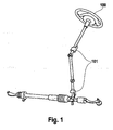
- a torque sensor This will be on Fig. 1 directed.
- 100 indicates the steering wheel and 101 indicates two possible mounting locations of a torque sensor, these are the upper and lower steering columns, respectively.
- the EPS motor must be placed below the torque sensor, ie the torque sensor must be located between the steering wheel and the EPS motor so that it detects the driver torque.
- a quantity representing the driver activity S is plotted. This size may be, for example, the steering wheel torque M.
- This figure shows a typical sequence of movements, first having a time-stationary phase t1 in which the driver has little activity. The low activity is determined by the fact that the amount of S always falls below the threshold value S1.
- This phase t1 is followed by a jerky movement sequence extending over the time interval t2, in which the threshold value D2 is reached or exceeded.
- This pattern sequence represents a typical sequence of driver steering movement during over-fatigue. Due to fatigue, the driver shows a rapid jerky back-and-forth motion of the steering wheel in the time interval t2.
- This temporal motion scheme is measured by means of a torque sensor and then analyzed by an algorithm.
- this information can be made available to another system in order to make the driver aware of his over-fatigue, for example by means of visual, acoustic or haptic warning information.
- the described system for checking the plausibility of another fatigue detection system.
- This may be, for example, a vision system which detects the eye and eyelid movements of the driver and is based on this on the fatigue of the driver is closed.
- a steering angle sensor detects the eye and eyelid movements of the driver and is based on this on the fatigue of the driver is closed.
- a profile of the driver's steering movements can be created, which in turn can be concluded on a fatigue.
- the invention can also be used to analyze further movement patterns of the driver, eg avoidance maneuvers or a "sporty driving style".
- a torque quantity representing the torque applied by the driver to the steering wheel is detected in block 301.
- a query is made in block 302 as to whether there is a sudden change in the torque magnitude. If there is a jerky change in torque magnitude, then in block 303, the presence of driver fatigue is detected. However, if no jerky change in torque magnitude is detected in block 302, then the block is returned to block 300 and the process is performed anew.
Abstract
Claims (5)
- Procédé de détection de la fatigue d'un conducteur d'un véhicule dans lequel une grandeur du couple de rotation représentant le couple de rotation appliqué par le conducteur sur le volant de direction (100) est déterminée (301) et que la présence d'une fatigue du conducteur est détectée à l'aide de la grandeur du couple de rotation (303), caractérisé en ce qu'une fatigue du conducteur est détectée comme présente lorsque la grandeur du couple de rotation :- passe en dessous d'une première valeur seuil (S1) prédéfinie pendant un premier intervalle de temps de longueur prédéfinie ;- passe en dessus d'une deuxième valeur seuil (S2) prédéfinie pendant un deuxième intervalle de temps ultérieur de longueur prédéfinie ; et- l'écart de temps entre la fin du premier intervalle de temps et le début du deuxième intervalle de temps se situe en dessous d'une troisième valeur seuil.
- Procédé selon la revendication 1, caractérisé en ce que la grandeur du couple de rotation est déterminée à l'aide d'un capteur de couple de rotation (101).
- Procédé selon la revendication 2, caractérisé en ce que le capteur de couple de rotation (101) est placé au niveau de la colonne de direction.
- Procédé selon l'une quelconque des revendications 1 à 3, caractérisé en ce qu'en cas de fatigue détectée du conducteur, le conducteur en est averti ou informé.
- Dispositif contenant des moyens conçus pour mettre en oeuvre le procédé précédemment décrit.
Applications Claiming Priority (2)
| Application Number | Priority Date | Filing Date | Title |
|---|---|---|---|
| DE102007001362A DE102007001362A1 (de) | 2007-01-09 | 2007-01-09 | Verfahren und Vorrichtung zur Fahrerermüdungserkennung mittels Drehmomentsensorik |
| PCT/EP2007/061978 WO2008083870A1 (fr) | 2007-01-09 | 2007-11-07 | Procédé et dispositif pour détecter la fatigue d'un conducteur au moyen d'un système de détection de couple de rotation |
Publications (2)
| Publication Number | Publication Date |
|---|---|
| EP2117870A1 EP2117870A1 (fr) | 2009-11-18 |
| EP2117870B1 true EP2117870B1 (fr) | 2012-03-14 |
Family
ID=39431101
Family Applications (1)
| Application Number | Title | Priority Date | Filing Date |
|---|---|---|---|
| EP07822292A Active EP2117870B1 (fr) | 2007-01-09 | 2007-11-07 | Procédé et dispositif pour détecter la fatigue d'un conducteur au moyen d'un système de détection de couple de rotation |
Country Status (5)
| Country | Link |
|---|---|
| US (1) | US8374750B2 (fr) |
| EP (1) | EP2117870B1 (fr) |
| JP (2) | JP5324469B2 (fr) |
| DE (1) | DE102007001362A1 (fr) |
| WO (1) | WO2008083870A1 (fr) |
Cited By (1)
| Publication number | Priority date | Publication date | Assignee | Title |
|---|---|---|---|---|
| DE102014206626A1 (de) | 2014-04-07 | 2015-10-08 | Bayerische Motoren Werke Aktiengesellschaft | Müdigkeitserkennung mithilfe von Datenbrillen (HMD) |
Families Citing this family (15)
| Publication number | Priority date | Publication date | Assignee | Title |
|---|---|---|---|---|
| DE102007001362A1 (de) | 2007-01-09 | 2008-07-10 | Robert Bosch Gmbh | Verfahren und Vorrichtung zur Fahrerermüdungserkennung mittels Drehmomentsensorik |
| JP4483984B2 (ja) * | 2008-08-28 | 2010-06-16 | トヨタ自動車株式会社 | ドライバ状態推定装置 |
| DE102008042277B4 (de) * | 2008-09-23 | 2011-04-21 | Robert Bosch Gmbh | Vorrichtung und Verfahren zur Erkennung des Kontaktzustandes an einer Welle oder Achse (Lenkrad) |
| DE102009028647A1 (de) * | 2009-08-19 | 2011-02-24 | Zf Lenksysteme Gmbh | Verfahren und Vorrichtung zum Erkennen eines Bedienzustands eines Lenkrads in einem Fahrzeug |
| CN102696061B (zh) * | 2009-09-30 | 2015-01-07 | 本田技研工业株式会社 | 驾驶员状态判断装置 |
| DE102009047323A1 (de) * | 2009-12-01 | 2011-06-09 | Zf Lenksysteme Gmbh | Verfahren und Vorrichtung zum Erkennen eines Ermüdungszustands des Fahrers eines Fahrzeugs |
| DE102010049086A1 (de) * | 2010-10-21 | 2012-04-26 | Gm Global Technology Operations Llc (N.D.Ges.D. Staates Delaware) | Verfahren zum Beurteilen der Fahreraufmerksamkeit |
| JP5541145B2 (ja) * | 2010-12-22 | 2014-07-09 | 日産自動車株式会社 | 運転者の疲労推定装置 |
| DE102013209949A1 (de) | 2013-05-28 | 2014-12-04 | Robert Bosch Gmbh | Verfahren zur Müdigkeitserkennung des Fahrers eines Fahrzeugs |
| TWI587249B (zh) | 2013-08-06 | 2017-06-11 | 新唐科技股份有限公司 | 警示方法和警示系統 |
| EP2862741B1 (fr) * | 2013-10-15 | 2017-06-28 | Volvo Car Corporation | Dispositif d'assistance de conducteur de véhicule |
| FR3013297B1 (fr) * | 2013-11-18 | 2017-02-17 | Peugeot Citroen Automobiles Sa | Systeme de surveillance de l'etat de vigilance du conducteur d'un vehicule automobile |
| KR102228559B1 (ko) | 2014-10-13 | 2021-03-16 | 현대모비스 주식회사 | 운전자 피로 감지 방법 및 시스템 |
| JP6759538B2 (ja) * | 2015-07-31 | 2020-09-23 | アイシン精機株式会社 | 駐車支援装置及び駐車支援方法 |
| CN106314149A (zh) * | 2016-08-25 | 2017-01-11 | 乐视控股(北京)有限公司 | 一种控制疲劳驾驶的方法和装置 |
Family Cites Families (28)
| Publication number | Priority date | Publication date | Assignee | Title |
|---|---|---|---|---|
| JPS562226A (en) * | 1979-06-13 | 1981-01-10 | Nissan Motor Co Ltd | Dozing drive detector |
| US4463347A (en) | 1980-09-22 | 1984-07-31 | Nissan Motor Company, Ltd. | Drowsiness alarm system for a vehicle |
| JPS5766025A (en) | 1980-10-06 | 1982-04-22 | Nissan Motor Co Ltd | Alarming device for vehicle |
| FR2614481B1 (fr) * | 1987-02-13 | 1990-08-31 | Pk I | Procede de commande d'un moteur asynchrone et entrainement electrique mettant ce procede en application |
| JPH073360B2 (ja) * | 1987-03-27 | 1995-01-18 | 株式会社日立製作所 | 軸ねじり振動監視装置 |
| JPH0518198Y2 (fr) * | 1988-03-09 | 1993-05-14 | ||
| JP3064527B2 (ja) | 1991-07-12 | 2000-07-12 | 鹿島建設株式会社 | セグメントの荷役装置 |
| US6553130B1 (en) * | 1993-08-11 | 2003-04-22 | Jerome H. Lemelson | Motor vehicle warning and control system and method |
| JPH07266917A (ja) * | 1994-03-31 | 1995-10-17 | Toyota Motor Corp | 居眠り運転検出装置 |
| JP3647538B2 (ja) | 1996-02-12 | 2005-05-11 | 本田技研工業株式会社 | 車両操舵装置 |
| JP3241268B2 (ja) * | 1996-06-12 | 2001-12-25 | 本田技研工業株式会社 | 電動パワースライドドア装置 |
| US5921780A (en) * | 1996-06-28 | 1999-07-13 | Myers; Nicole J. | Racecar simulator and driver training system and method |
| JP3424470B2 (ja) * | 1996-12-05 | 2003-07-07 | トヨタ自動車株式会社 | 運転異常検出装置及び運転警報装置 |
| WO2001060254A1 (fr) * | 2000-02-15 | 2001-08-23 | Active Attention Ab | Procede et organe permettant de surveiller la vivacite d'un conducteur |
| SE0002804D0 (sv) * | 2000-08-01 | 2000-08-01 | Promind Ab | Teknik för att fortlöpande kartlägga fordons/förares uppträdande/beteende för att fastställa fordons reaktionskoefficient resp. förares kompetenskoefficient, samt anordning för grafisk presentation av dessa koefficienter |
| DE10358114A1 (de) * | 2002-12-23 | 2004-07-01 | Luk Lamellen Und Kupplungsbau Beteiligungs Kg | Getriebe mit stufenlos verstellbarer Übersetzung, mit oder ohne Leistungsverzweigung sowie mit und ohne E-Maschine |
| US6946965B2 (en) * | 2002-12-30 | 2005-09-20 | Young Thomas W | Driver fatigue detector with automatic deactivation |
| JP4189664B2 (ja) * | 2003-09-29 | 2008-12-03 | 株式会社デンソー | 電動パワーステアリング制御装置 |
| CN100436227C (zh) * | 2003-10-02 | 2008-11-26 | 日产自动车株式会社 | 车辆转向装置 |
| DE10350276A1 (de) * | 2003-10-28 | 2005-06-02 | Robert Bosch Gmbh | Vorrichtung zur Ermüdungswarnung in Kraftfahrzeugen mit Abstandswarnsystem |
| US7064507B2 (en) * | 2004-02-17 | 2006-06-20 | Railpower Technologies Corp. | Managing wheel skid in a locomotive |
| DE102004047136A1 (de) | 2004-09-27 | 2006-04-13 | Daimlerchrysler Ag | Verfahren zum Erlernen der Reaktionen des Fahrers eines Fahrzeugs |
| ATE387332T1 (de) | 2004-10-08 | 2008-03-15 | Fiat Ricerche | Vorrichtung zum erfassen der handlung eines fahrers an einem lenkrad eines lenksystems eines kraftfahrzeuges |
| DE102005030934B4 (de) * | 2005-06-30 | 2007-04-12 | Benteler Automobiltechnik Gmbh | Instrumententräger und Kraftfahrzeug |
| FR2890632B1 (fr) * | 2005-09-14 | 2007-11-16 | Koyo Steering Europ K S E Soc | Procede pour la detection de la tenue d'un volant de conduite d'une direction assistee electronique de vehicule automobile |
| DE102005057267A1 (de) | 2005-12-01 | 2007-06-06 | Robert Bosch Gmbh | Verfahren und Vorrichtung zur Fahrerzustandserkennung |
| JP2008146515A (ja) * | 2006-12-13 | 2008-06-26 | Hitachi Ltd | 疲労度検出装置,自動車の制御装置および制御方法 |
| DE102007001362A1 (de) | 2007-01-09 | 2008-07-10 | Robert Bosch Gmbh | Verfahren und Vorrichtung zur Fahrerermüdungserkennung mittels Drehmomentsensorik |
-
2007
- 2007-01-09 DE DE102007001362A patent/DE102007001362A1/de active Pending
- 2007-11-07 US US12/308,314 patent/US8374750B2/en active Active
- 2007-11-07 JP JP2009544375A patent/JP5324469B2/ja not_active Expired - Fee Related
- 2007-11-07 WO PCT/EP2007/061978 patent/WO2008083870A1/fr active Application Filing
- 2007-11-07 EP EP07822292A patent/EP2117870B1/fr active Active
-
2013
- 2013-07-08 JP JP2013142582A patent/JP5650815B2/ja active Active
Cited By (1)
| Publication number | Priority date | Publication date | Assignee | Title |
|---|---|---|---|---|
| DE102014206626A1 (de) | 2014-04-07 | 2015-10-08 | Bayerische Motoren Werke Aktiengesellschaft | Müdigkeitserkennung mithilfe von Datenbrillen (HMD) |
Also Published As
| Publication number | Publication date |
|---|---|
| WO2008083870A1 (fr) | 2008-07-17 |
| JP2010515960A (ja) | 2010-05-13 |
| JP5650815B2 (ja) | 2015-01-07 |
| JP2014013571A (ja) | 2014-01-23 |
| JP5324469B2 (ja) | 2013-10-23 |
| DE102007001362A1 (de) | 2008-07-10 |
| US8374750B2 (en) | 2013-02-12 |
| EP2117870A1 (fr) | 2009-11-18 |
| US20100191422A1 (en) | 2010-07-29 |
Similar Documents
| Publication | Publication Date | Title |
|---|---|---|
| EP2117870B1 (fr) | Procédé et dispositif pour détecter la fatigue d'un conducteur au moyen d'un système de détection de couple de rotation | |
| EP3448740B1 (fr) | Détection mains sur volant/libres dans un système de direction à commande par câble | |
| EP3717332B1 (fr) | Procédé de commande d'un système de direction par câble à retour actif | |
| EP1292485B1 (fr) | Procede de detection de la position des mains sur un volant | |
| DE602005005683T2 (de) | Haptische Anzeige umfassend ein Gaspedal für ein Kraftfahrzeug | |
| EP2513525B1 (fr) | Dispositif pour generer une force de rappel supplementaire sur la pedale d'accelerateur et procede pour son fonctionnement | |
| DE102007021982A1 (de) | Fahrpedal-System | |
| DE102013209459A1 (de) | Verfahren und Vorrichtung zur Erkennung des Kontakts von Händen mit dem Lenkrad eines Kraftfahrzeugs | |
| DE102011002997A1 (de) | Verfahren zum Erkennen einer freihändigen Fahrsituation eines Kraftfahrzeuges | |
| DE102008042277B4 (de) | Vorrichtung und Verfahren zur Erkennung des Kontaktzustandes an einer Welle oder Achse (Lenkrad) | |
| EP1863682B1 (fr) | Procede de generation d'un signal de declenchement pour un dispositif de protection des pietons | |
| WO2019162032A1 (fr) | Dispositif et procédé de fonctionnement d'un véhicule au moins partiellement mobile de manière automatisée | |
| DE102004026407B4 (de) | Verfahren zur Steuerung einer einstellbaren Rückstellkraft auf ein Fahrpedal in einem Fahrzeug | |
| DE102007026065B4 (de) | Lenkmittel und Verfahren zur Erzeugung eines Signals | |
| DE102015216390B3 (de) | Vorrichtung und Verfahren zur Generierung eines haptischen Momentes an einem Aktor | |
| DE102020206435A1 (de) | Verfahren zur Beeinflussung einer Bewegung einer Lenkhandhabe eines Steer-by-Wire-Lenksystems in einem Fahrzeug | |
| DE102019214584A1 (de) | Vorrichtung und Verfahren zum Ansteuern einer Funktion eines Kraftfahrzeugs | |
| DE102012013546A1 (de) | Verfahren zum Betrieb einer Assistenzvorrichtung eines Fahrzeuges | |
| EP1157915A2 (fr) | Procédé de commande de l'angle de direction d'un véhicule et un système pour exécuter un tel procédé | |
| DE102008046866A1 (de) | Verfahren zur Einstellung eines Zusatzlenkmoments in einer Lenkeinrichtung eines Kraftfahrzeugs zur Erzeugung einer haptischen Lenkradwarnung beim Spurverlassen | |
| DE102008026729A1 (de) | Elektromechanische Lenkung mit einem System zur Warnung eines Fahrers vor einer Funktionsstörung und Verfahren zur Fahrerwarnung | |
| DE102010006666A1 (de) | Verfahren zum Erkennen einer Schneekette an einem Fahrzeug | |
| DE102009047323A1 (de) | Verfahren und Vorrichtung zum Erkennen eines Ermüdungszustands des Fahrers eines Fahrzeugs | |
| EP2265838B1 (fr) | Procédé et dispositif de fermeture d'un accouplement | |
| DE102020210762A1 (de) | Verfahren zur Durchführung einer Parklückenerkennung |
Legal Events
| Date | Code | Title | Description |
|---|---|---|---|
| PUAI | Public reference made under article 153(3) epc to a published international application that has entered the european phase |
Free format text: ORIGINAL CODE: 0009012 |
|
| 17P | Request for examination filed |
Effective date: 20090810 |
|
| AK | Designated contracting states |
Kind code of ref document: A1 Designated state(s): AT BE BG CH CY CZ DE DK EE ES FI FR GB GR HU IE IS IT LI LT LU LV MC MT NL PL PT RO SE SI SK TR |
|
| 17Q | First examination report despatched |
Effective date: 20100301 |
|
| DAX | Request for extension of the european patent (deleted) | ||
| GRAP | Despatch of communication of intention to grant a patent |
Free format text: ORIGINAL CODE: EPIDOSNIGR1 |
|
| GRAS | Grant fee paid |
Free format text: ORIGINAL CODE: EPIDOSNIGR3 |
|
| GRAA | (expected) grant |
Free format text: ORIGINAL CODE: 0009210 |
|
| AK | Designated contracting states |
Kind code of ref document: B1 Designated state(s): DE FR GB |
|
| RBV | Designated contracting states (corrected) |
Designated state(s): DE FR GB |
|
| REG | Reference to a national code |
Ref country code: GB Ref legal event code: FG4D Free format text: NOT ENGLISH |
|
| REG | Reference to a national code |
Ref country code: DE Ref legal event code: R096 Ref document number: 502007009493 Country of ref document: DE Effective date: 20120510 |
|
| PLBE | No opposition filed within time limit |
Free format text: ORIGINAL CODE: 0009261 |
|
| STAA | Information on the status of an ep patent application or granted ep patent |
Free format text: STATUS: NO OPPOSITION FILED WITHIN TIME LIMIT |
|
| 26N | No opposition filed |
Effective date: 20121217 |
|
| REG | Reference to a national code |
Ref country code: DE Ref legal event code: R097 Ref document number: 502007009493 Country of ref document: DE Effective date: 20121217 |
|
| PGFP | Annual fee paid to national office [announced via postgrant information from national office to epo] |
Ref country code: FR Payment date: 20131119 Year of fee payment: 7 Ref country code: GB Payment date: 20131122 Year of fee payment: 7 |
|
| GBPC | Gb: european patent ceased through non-payment of renewal fee |
Effective date: 20141107 |
|
| REG | Reference to a national code |
Ref country code: FR Ref legal event code: ST Effective date: 20150731 |
|
| PG25 | Lapsed in a contracting state [announced via postgrant information from national office to epo] |
Ref country code: GB Free format text: LAPSE BECAUSE OF NON-PAYMENT OF DUE FEES Effective date: 20141107 |
|
| PG25 | Lapsed in a contracting state [announced via postgrant information from national office to epo] |
Ref country code: FR Free format text: LAPSE BECAUSE OF NON-PAYMENT OF DUE FEES Effective date: 20141201 |
|
| PGFP | Annual fee paid to national office [announced via postgrant information from national office to epo] |
Ref country code: DE Payment date: 20240123 Year of fee payment: 17 |