EP2116273A2 - Verfahren zur Herstellung eines Katheters - Google Patents
Verfahren zur Herstellung eines Katheters Download PDFInfo
- Publication number
- EP2116273A2 EP2116273A2 EP09164911A EP09164911A EP2116273A2 EP 2116273 A2 EP2116273 A2 EP 2116273A2 EP 09164911 A EP09164911 A EP 09164911A EP 09164911 A EP09164911 A EP 09164911A EP 2116273 A2 EP2116273 A2 EP 2116273A2
- Authority
- EP
- European Patent Office
- Prior art keywords
- tube
- catheter
- mandrel
- needle
- distal
- Prior art date
- Legal status (The legal status is an assumption and is not a legal conclusion. Google has not performed a legal analysis and makes no representation as to the accuracy of the status listed.)
- Granted
Links
Images


Classifications
-
- A—HUMAN NECESSITIES
- A61—MEDICAL OR VETERINARY SCIENCE; HYGIENE
- A61M—DEVICES FOR INTRODUCING MEDIA INTO, OR ONTO, THE BODY; DEVICES FOR TRANSDUCING BODY MEDIA OR FOR TAKING MEDIA FROM THE BODY; DEVICES FOR PRODUCING OR ENDING SLEEP OR STUPOR
- A61M25/00—Catheters; Hollow probes
- A61M25/0009—Making of catheters or other medical or surgical tubes
- A61M25/001—Forming the tip of a catheter, e.g. bevelling process, join or taper
-
- A—HUMAN NECESSITIES
- A61—MEDICAL OR VETERINARY SCIENCE; HYGIENE
- A61M—DEVICES FOR INTRODUCING MEDIA INTO, OR ONTO, THE BODY; DEVICES FOR TRANSDUCING BODY MEDIA OR FOR TAKING MEDIA FROM THE BODY; DEVICES FOR PRODUCING OR ENDING SLEEP OR STUPOR
- A61M25/00—Catheters; Hollow probes
- A61M25/0067—Catheters; Hollow probes characterised by the distal end, e.g. tips
- A61M25/0068—Static characteristics of the catheter tip, e.g. shape, atraumatic tip, curved tip or tip structure
-
- A—HUMAN NECESSITIES
- A61—MEDICAL OR VETERINARY SCIENCE; HYGIENE
- A61M—DEVICES FOR INTRODUCING MEDIA INTO, OR ONTO, THE BODY; DEVICES FOR TRANSDUCING BODY MEDIA OR FOR TAKING MEDIA FROM THE BODY; DEVICES FOR PRODUCING OR ENDING SLEEP OR STUPOR
- A61M25/00—Catheters; Hollow probes
- A61M25/01—Introducing, guiding, advancing, emplacing or holding catheters
- A61M25/06—Body-piercing guide needles or the like
- A61M25/0606—"Over-the-needle" catheter assemblies, e.g. I.V. catheters
-
- B—PERFORMING OPERATIONS; TRANSPORTING
- B29—WORKING OF PLASTICS; WORKING OF SUBSTANCES IN A PLASTIC STATE IN GENERAL
- B29C—SHAPING OR JOINING OF PLASTICS; SHAPING OF MATERIAL IN A PLASTIC STATE, NOT OTHERWISE PROVIDED FOR; AFTER-TREATMENT OF THE SHAPED PRODUCTS, e.g. REPAIRING
- B29C48/00—Extrusion moulding, i.e. expressing the moulding material through a die or nozzle which imparts the desired form; Apparatus therefor
- B29C48/03—Extrusion moulding, i.e. expressing the moulding material through a die or nozzle which imparts the desired form; Apparatus therefor characterised by the shape of the extruded material at extrusion
- B29C48/09—Articles with cross-sections having partially or fully enclosed cavities, e.g. pipes or channels
-
- B—PERFORMING OPERATIONS; TRANSPORTING
- B29—WORKING OF PLASTICS; WORKING OF SUBSTANCES IN A PLASTIC STATE IN GENERAL
- B29C—SHAPING OR JOINING OF PLASTICS; SHAPING OF MATERIAL IN A PLASTIC STATE, NOT OTHERWISE PROVIDED FOR; AFTER-TREATMENT OF THE SHAPED PRODUCTS, e.g. REPAIRING
- B29C48/00—Extrusion moulding, i.e. expressing the moulding material through a die or nozzle which imparts the desired form; Apparatus therefor
- B29C48/03—Extrusion moulding, i.e. expressing the moulding material through a die or nozzle which imparts the desired form; Apparatus therefor characterised by the shape of the extruded material at extrusion
- B29C48/13—Articles with a cross-section varying in the longitudinal direction, e.g. corrugated pipes
-
- A—HUMAN NECESSITIES
- A61—MEDICAL OR VETERINARY SCIENCE; HYGIENE
- A61M—DEVICES FOR INTRODUCING MEDIA INTO, OR ONTO, THE BODY; DEVICES FOR TRANSDUCING BODY MEDIA OR FOR TAKING MEDIA FROM THE BODY; DEVICES FOR PRODUCING OR ENDING SLEEP OR STUPOR
- A61M25/00—Catheters; Hollow probes
- A61M25/0021—Catheters; Hollow probes characterised by the form of the tubing
- A61M25/0023—Catheters; Hollow probes characterised by the form of the tubing by the form of the lumen, e.g. cross-section, variable diameter
-
- B—PERFORMING OPERATIONS; TRANSPORTING
- B29—WORKING OF PLASTICS; WORKING OF SUBSTANCES IN A PLASTIC STATE IN GENERAL
- B29C—SHAPING OR JOINING OF PLASTICS; SHAPING OF MATERIAL IN A PLASTIC STATE, NOT OTHERWISE PROVIDED FOR; AFTER-TREATMENT OF THE SHAPED PRODUCTS, e.g. REPAIRING
- B29C48/00—Extrusion moulding, i.e. expressing the moulding material through a die or nozzle which imparts the desired form; Apparatus therefor
- B29C48/03—Extrusion moulding, i.e. expressing the moulding material through a die or nozzle which imparts the desired form; Apparatus therefor characterised by the shape of the extruded material at extrusion
- B29C48/12—Articles with an irregular circumference when viewed in cross-section, e.g. window profiles
Definitions
- This invention relates to the field of medical devices for the introduction and removal of fluids from a patient. More particularly, the invention relates to a method of manufacturing catheters for use with a needle.
- IV catheters such as intravenous catheters
- IV catheters have been developed for insertion into the tissues of a body cavity of a patient to introduce or remove fluids.
- Such devices are most commonly intended for intravascular use, particularly for infusion of normal intravenous solutions, including antibiotics and other drug.
- IV catheters are also used to withdraw blood from the patient for normal blood-gas analysis as well as other blood work. While IV catheters are available in several different types, one common type of catheter is constructed so as to be mounted coaxially upon a relatively long, hollow needle or cannula with a slight friction fit, referred to herein as an "over-the-needle" arrangement. A hub is attached at one end of the catheter and is designed so as to be connectable with and detachable from an IV fluid supply line. To insert the catheter into the patient, the needle and catheter together are inserted through the patient's skin, whereupon the needle may be withdrawn, leaving the catheter in place.
- the catheter Since the catheter will normally be left in position for at least several hours, it must be flexible and efficiently shaped for the introduction of fluid or removal of fluid.
- the shape of the catheter tip must produce minimal trauma to the patient during insertion of the catheter into the patient and while the catheter is in place in the patient.
- a tip shape that provides these characteristics has a tapered outer wall and an angled tip and is disclosed in U.S. Patent No. 4,588,398 , incorporated herein by reference.
- a process for making such a catheter tip is disclosed in U.S. Patent No. 4,661,300 , incorporated herein by reference. In this process, the catheter is placed on a mandrel.
- a die having an interior molding surface, which is tapered according to the tip desired on the catheter, is aligned axially with the mandrel.
- the die is heated, typically using RF energy, thereby heating the catheter tip so that it becomes flowable.
- the mandrel and die are brought together so the distal edge of the mandrel engages the tapered portion of the die. This action cleanly forms a smooth and uniform tapered tip for the catheter but has not been designed specifically to address formation of the internal geometry of the catheter and is incapable of achieving the preferred geometry of the instant invention.
- Catheters must be designed of materials and to have shapes that are rigid enough to pass through the tissue of the patient and yet soft enough to avoid discomfort and tissue trauma to the patient when in place.
- the forces exerted on the flexible catheter by the patient's tissue may cause a "peeling back" of the catheter, preventing the catheter from full insertion into the patient's vein.
- This problem can be compounded when the needle and catheter must be inserted into a septum of an implantable infusion port (such ports may be implanted in a patient for long term vascular access). These ports may provide a higher resistive force than human tissue. Consequently, the catheter, particularly its tip, must include some structural rigidity.
- a method of forming a catheter corresponding to the first part of claim 1 is described in WO 01/89412 A2 .
- This method includes positioning of a mandrel within the lumen of a flexible tube, said mandrel having a body portion and a tip portion connected through a ledge.
- the tube is surrounded by a shrink tubing.
- the tube is pressed onto the mandrel.
- Another method described in this reference provides inserting the mandrel with the surrounding tube into a hot die. In this case, the mandrel does not have a body portion and a tip portion of smaller diameter. The mandrel extends past the opening of the tube lumen.
- U.S. 5,409,644 discloses a method of making a catheter tip an a main body of a thermoplastic synthetic plastics material.
- a tube surrounding a mandrel is inserted into a hot die.
- the mandrel has a main part, a converging part and a leading part. The leading part extends beyond the tube end.
- the method provides a relative movement between the die and the mandrel causing the material of the tube to flow axially to create a tip section and thereby lengthen the tube.
- the method of the invention is defined by claim 1.
- a method for forming a catheter for insertion into a patient's skin.
- a flexible, biocompatible material is extruded into a tube.
- the tube has an inner wall defining a substantially constant inner cross-section, an outer wall defining a substantially constant outer cross-section and an axis.
- a lumen is defined by the inner wall and extends coaxially within the tube from a proximal portion, through a distal portion to a distal face, forming an opening in the distal face of the tube.
- a mandrel is provided that has a body portion and a tip portion. The body portion has a larger cross-section than the tip portion.
- the body portion has a cross-section that is the same as or less than the inner cross-section of the tube.
- the mandrel is inserted into the lumen such that the tip portion of the mandrel is disposed in the distal portion of the tube proximate to the distal face of the tube.
- the distal portion of the tube is deformed such that the outer wall tapers inward toward the opening and the inner wall conforms to the tip portion of the mandrel.
- the portion of the tube's inner wall that has conformed to the tip portion of the mandrel defines a catheter land having a predetermined cross-section substantially matching the cross-section of the tip portion and a predetermined length.
- the catheter is cured and the mandrel is withdrawn from the lumen.
- the material of the tube is thermoplastic and is deformed by heating in a hot die.
- Other plastic materials may be employed and may be formed as necessary, including any required curing steps, to achieve the desired geometry.
- the mandrel may be positioned so that the free end of the mandrel is co-located with the distal opening in the tube, or so that the free end extends through the distal opening.
- the tip portion of the mandrel may have various shapes to impart a desired geometry to the catheter land, such as grooves to form ridges in the land, or a conical shape to form a conical land. Such ridges may be employed to direct the tearing of a catheter when use as a splittable introducer, such as disclosed in U.S. Patent 6,080,141 , U.S. Patent 6,027,480 and U.S. Patent 6,273,871 , each incorporated herein by reference.
- the needle itself may be used as the mandrel, and may be heated to assist forming the catheter.
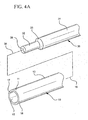
- Fig. 1 is an exploded view of a catheter and needle assembly.
- Fig. 2 is a cut-away view of a catheter.
- Fig. 3 is a cut-away view of the catheter of Fig. 2 shown mounted on a needle, forming an over-the-needle catheter assembly.
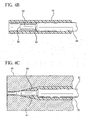
- Fig. 4A is an expanded view of a mandrel being positioned in a tube, not in accord with the instant invention.
- Fig. 4B is a partial cut-away view of the mandrel depicted in Fig. 4A seated within the tube.
- Fig. 4C is a partial cut-away view of the tube of Fig. 4B being deformed in a hot die.
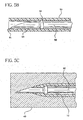
- Fig. 5A is an expanded view of a needle being positioned in a tube in accord with the instant invention.
- Fig. 5B is a partial cut-away view of the needle depicted in Fig. 5A seated within the tube.
- Fig. 5C is a partial cut-away view of the tube of Fig. 5B being deformed in a hot die in which the needle is serving as a mandrel.
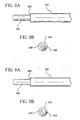
- Figs. 6A and 6B are front and side elevation views, respectively, of a mandrel not in accord with this invention.
- Figs. 7A and 7B are front and side elevation views, respectively, of a mandrel not in accord with this invention.
- Figs. 8A and 8B are front and side elevation views, respectively, of mandrel not in accord with this invention.
- Figs. 9A and 9B are front and side elevation views, respectively, of a mandrel not in accord with this invention.
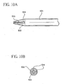
- Figs. 10A and 10B are front and side elevation views, respectively, of a mandrel of this invention.
- Fig. 11 is a cut-away side view of a catheter formed in accord with the invention shown mounted to a needle.
- Fig. 12 is a cut-away side view of a catheter formed in accord with the invention mounted to a needle with no discontinuity.
- proximal refers to a location on the catheter and introducer needle assembly that, during normal use, is closest to the clinician using the device and farthest from the patient in connection with whom the device is used (the left side of Figs. 2 and 3 ).
- distal refers to a location on the catheter and introducer needle assembly that, during normal use, is farthest from the clinician using the device and closest to the patient in connection with whom the device is used (the right side in Figs. 2 and 3 ).
- an aspect of the instant invention is related to flexible catheters 1 for use in connection with an over-the-needle catheter assembly 100 and their manufacture.
- the catheter I formed in accord with the instant invention includes a distal portion 11 and a proximal portion 12.
- the catheter includes an outer wall 13 and an inner wall 14, with a central lumen 15 extending axially therein and defining a fluid flow path from the tip 20 of the catheter through to the proximal end of the catheter..
- the tip 20 of the catheter is shaped to form a beveled surface 21, such as disclosed in U.S. Patent 4,588,398 incorporated herein by reference.
- the beveled surface is designed to smoothly pass through the patient's tissue and to cause minimal discomfort and abrasion while positioned within the tissue.
- the tip may have other shapes and still practice aspects of the invention.
- a needle 50 is typically made of stainless steel and includes a central axial cavity extending completely through the needle to the needle tip 51.
- the needle is inserted coaxially into the lumen 1 of the catheter to form a catheter assembly 100.
- the combination is inserted under a patient's skin, typically into the patient's vein.
- the needle's tip 51 is ground to a sharp bevel to ease insertion into the patient.
- the catheter is employed in conjunction with a needle 50 including a discontinuity 52.
- a discontinuity may be useful for, inter alia , allowing capture of the needle tip in a casing after use, thereby reducing incidents of inadvertent needle sticks, such as disclosed in U.S. Patent 6,004,294 and U.S Application Serial No.
- a notch 70 may be formed in the needle, proximal to the discontinuity, thereby creating a flash chamber of the central lumen 15 which provides a visual indication to a caregiver that he has successfully inserted the needle into a vein.
- the needle is removed and the catheter remains, providing access through the lumen to the patient's blood stream.
- the proximal portion 12 of the catheter may be provided with various mechanisms, such as septums, luer locks, and the like, to provide selective access to the lumen (and, thereby, the patient's blood stream), as would be appreciated by one skilled in the art.
- the catheter 1 formed in accord with the instant invention includes a predetermined internal geometry, defining the shape of the lumen 15 to improve operation of the over-the-needle catheter assembly 100.
- the catheter includes a catheter land 22 disposed at the distal portion 11 of the catheter at the tip 20, a proximal wall 24 (that is, the portion of the inner wall 14 at the proximal end of the catheter) and a shoulder 23 connecting the land to the proximal wall.
- the land has a circular cross-section with a constant diameter and a length equal to (or slightly less than) the needle tip length 53 (that is, referring to Fig.
- the diameter of the land is preferably slightly less than the diameter of the needle near the tip such that there is a friction fit between the land and the needle.
- the proximal wall also has a predetermined length and, preferably, a circular cross-section.
- the shoulder 23 preferably has a conical shape, connecting the land with the proximal wall.
- a tube 10 is formed of a flexible, biocompatible material, such as polytetrafluoroethylene (such as TEFLON®), polyvinyl chloride, polyethylene, polyurethane, polypropylene, or polyether urethane.
- the tube includes an inner wall 14 and an outer wall 13, each of which typically have substantially constant, circular cross-sections, thereby forming a straight tube.
- the tube 10 is formed by extrusion or injection molding. The dimensions of the tube will vary depending an the application.
- the inner wall 13 of the tube may have a diameter of 0,35 to 3,0 mm (0,014 to 0,120 inches) and the outer wall 14 may have an outer diameter of 0,51 to 3,5 mm (0,020 to 0,140 inches).
- the tube may be manufactured using various techniques and will have dimensions appropriate for particular applications.
- a lumen 15 extends through the tube 10 and has a lumen axis 16.
- the tube itself has a distal portion 11 and a proximal portion 12.
- a distal face 17 of the tube is located remote from the proximal portion of the tube.
- the distal face 17 of the tube is in a plane perpendicular to the axis 16 of the tube. Consequently, a right angle is formed between the distal face and the outer wall 13. When passing through the patient's skin and into the vein, this right angle would contact the patient's skin, increasing the force required to insert the catheter and the discomfort felt by the patient.
- the catheter tip 20 is formed to a smooth bevel 21, such as depicted in Figs. 1 and 4C , or other shapes known in the art.
- the tip 20 of the catheter 1 is formed into a smooth bevel 21 using a mandrel 30 and a hot die 40.
- the mandrel includes a body portion 31 connected to the tip portion 32 by a ledge 33.
- the mandrel is a surface of rotation formed about a mandrel axis 34.
- the body portion has a cylindrical shape with an outer diameter about equal to (or slightly less than) the diameter of the inner wall 14 of the tube 10 and the tip portion has a cylindrical shape with an outer diameter about equal to (or slightly less than) the outer diameter of the tip 51 of the needle 50 to be inserted into the formed catheter.
- the outer diameter of the tip portion (and thus the internal diameter of the catheter land 22, discussed below) is slightly less than the outer diameter of the tip 51 of the needle 50 so that the catheter tip 20 has an interference fit on the needle tip.
- the interference fit is desirable so that when the over-the-needle catheter assembly 100 is taken out of its package, the catheter remains snugly on the needle and does not easily slip off. This interference fit also facilitates insertion of the over-the-needle catheter assembly into the patient's vein because it minimizes the chance that the catheter tip 20 will fold over or peel back on the needle tip 51, particularly in view of the structural support provided by the interaction of the discontinuity 52 and the shoulder 23.
- the specific dimensions of the mandrel will vary depending on the application intended for the catheter and the materials selected for the tube.
- the tip portion of the mandrel is slightly larger than the desired final size of the catheter tip because the catheter will shrink somewhat during cooling. Certain materials do not shrink and thus the mandrel tip portion is sized slightly smaller than the tip of the needle.
- the ledge 33 of the mandrel 30 has an angled peripheral surface, forming an angle of about 4 degrees with the axis 34 of the mandrel (this nearly-perpendicular relationship between the axis and the ledge is exaggerated for clarity's sake in Figs. 4A-4C ). It will be appreciated that the ledge could be at other angles with respect to the axis of the mandrel. In particular, the ledge could be formed at a right angle with the axis of the mandrel, thereby forming a straight shoulder in the catheter, as discussed more fully below, or at a 45 degree angle with respect to the axis 34.
- the ledge could also have other shapes, such as a convex or concave surface, as desired in a particular application of the invention.
- the ledge may also be formed asymmetrically about the mandrel axis such that the shoulder 23 formed in the catheter can engage the inserted needle 50 (or a feature 52 disposed thereon), preventing relative rotation, maintaining the catheter in a fixed orientation with respect to the needle.
- the mandrel 30 is inserted into the lumen 15 of the tube 10.
- the mandrel proceeds through the lumen until the free end 35 of the tip portion 32 of the mandrel is near to the opening 18 in the distal face 17 of the tube.
- the free end does not extend passed the opening.
- the tip portion of the mandrel and the distal portion of the tube are inserted into a hot die 40.
- the tube is made of a thermoplastic material that deforms in the die. The very distal portion of the tube is cut off in the mandrel (the trimmings are not shown in Fig. 4C ).
- the outer wall 13 of the tube contained within the die deforms to match the surface 41 of the die, creating a predetermined shape, such as the smooth bevel 21 depicted in Fig. 1 .
- the inner wall 14 of the tube within the die deforms to conform to the surface of the mandrel, such that the tube has a shoulder 23 formed at the ledge 33 of the mandrel and a catheter land 22 formed at the tip portion 32 of the mandrel.
- the catheter is cured by cooling.
- the mandrel or die may be cooled, cool air may be delivered to the catheter or cooling provided by other techniques.
- the catheter land and the shoulder will have a predetermined shape defined by the shape of the mandrel.
- the catheter is removed from the die and the mandrel is removed from the lumen 15.
- a needle 50 is inserted into the lumen such that the tip 51 of the needle extends beyond the tip 20 of the catheter.
- the needle is provided with a discontinuity 52, such as a bump or ledge formed on the exterior of the needle or attached to the exterior of the needle.
- the length of the catheter land 22 is selected such that the distal face or edge 54 of the discontinuity abuts the shoulder 23 in the catheter when the needle is positioned as desired in the lumen of the catheter.
- land 22 should be of a length less than the distance 53 between the distal face of the discontinuity and the proximal portion of the needle tip.
- the cross-section of the proximal wall 24 is selected to permit movement of the discontinuity 52 therethrough.
- the cross-section of the land is selected to prevent movement of the discontinuity therethrough, but to permit passage of the needle tip 51.
- the cross-section of the land is selected such that the needle tip sits snugly within the land, such as depicted in Fig. 3 .
- the land 22 may be shaped to mate with the distal face of the discontinuity while permitting fabrication of the catheter without difficulty.
- the needle 50 itself may be employed as a mandrel 30.
- the tipping process as discussed in connection with Figs. 4A-4C may also be employed when the needle serves as the mandrel.
- the needle may be positioned within the lumen 15 of the tube 10 such that the beveled tip 51 of the needle extends out of the opening 18 at the distal portion of the tube.
- the needle/tube combination is then inserted into a hot die 40.
- the discontinuity 52 on the needle serves as a ledge 33 and the shoulder 23 in the catheter 1 is formed directly onto the discontinuity, creating an over-the-needle assembly 100.
- the discontinuity 52 may have various shapes and be formed in various manners.
- the discontinuity may be formed by a crimp or notch in the needle.
- a shoulder may be ground into the needle wall to serve as a discontinuity.
- an annular ring may be attached to the needle to form the discontinuity.
- the discontinuity may have a beveled proximal face and distal face as shown in Fig. 4 , a beveled proximal face and a straight distal face as shown in Fig. 5A , or two straight faces as shown in Fig. 11 .
- Other shapes may be employed and still practice aspects of the invention. Indeed, aspects of the invention may be employed with needles that do not have a discontinuity (see Fig. 12 ).
- the catheter 1 and its tip 20 are preferably free of defects (such as incomplete formation, substantial flash, rollovers or jagged edges) and look smooth.
- a lubricant is used to allow the tipped catheter 1 to be easily removed from the mandrel 30 and die 40 without creating such a defect or stretching the formed catheter.
- the tipping lubricant may be a polydimethyl siloxane such as Dow Corning DC 360 or curable silicones such as Dow Corning 44159 MDX, which are amine terminated and moisture curable. Non-curable amine terminated polydimethyl siloxanes have also been used for this purpose. Such lubricants are described in, for example, U.S. Patents Nos.
- the amount of lubricant needed to provide adequate lubricity between the catheter and the mandrel and die is very small.
- the catheter may be dipped into a solution including the lubricant, thereby facilitating application of the lubricant to the inner wall 14 and the outer wall 13 of the tube before forming on the mandrel and die.
- the silicone oils used as typical lubricants are hydrophobic. Therefore, these compounds must be dissolved in solvents, as would be appreciated by one skilled in the art, in order to prepare a solution in which the catheter tip can be dipped for lubrication before tipping can begin.
- the tube 10 be made of a thermoplastic material which is formed into the catheter 1 in the hot die 40.
- the mandrel 30 itself could be heated (either alone or in combination with the die) to deform the tube.
- other plastic or polymeric materials may be employed to form the tube. If appropriate, these materials can be cured to maintain the shape formed by the mandrel and the die. For example, certain materials can be forced into the die, compressed into a shape matching the die and the mandrel, and cured to maintain that shape after removal of the die and the mandrel.
- Thermoset materials such as silicone and rubber, may be injected into a mold and cured with heat. Other such materials having various such properties may be employed and practice aspects of the invention.
- the proximal wall 24, the land 22 and the shoulder 23 may have different shapes and dimensions and still practice aspects of the invention.
- the length of the land may be selected such that a substantial portion of the needle tip 51 extends out of the catheter tip 20.
- the land length may be selected such that only a portion of the needle tip extends out of the catheter tip, or that the needle tip be completely enveloped within the catheter tip.
- the catheter may operate as a protective sleeve that needs to be removed before use.
- the cross-section of the land may also be selected so that it is smaller than the needle tip, thereby forming a tight fit with the needle tip and preventing any relative sliding until desired by the caregiver.
- the cross-section of the land may be an oval or other shape having a dimension less than the diameter of the needle tip, again creating a snug fit with the needle tip.
- the land may be provided with features such as tabs or ribs to create a structural relationship between the land and the tip as desired in any particular application of the instant invention. Such features allow control of the friction between the tip and the land, the flexibility of the external surface of the catheter tip, and other characteristics of the over-the-needle catheter assembly.
- a notch 70 may be positioned in the needle 50 distal to the discontinuity 52.
- the notch creates a passageway between the central axial cavity of the needle and the lumen 15 of the catheter 1.
- the shoulder 23 may also have various shapes and dimensions as desired to achieve characteristics desired in a particular application. As discussed above, the shoulder may be shaped to match the distal surface or edge 54 of the discontinuity 52. As seen in Fig. 3 , the shoulder has a conical shape to match the bevel on the discontinuity. The shoulder may also be formed at a right angle with respect to the axis of the catheter if the discontinuity has a flat, perpendicular distal surface. Alternatively, the shoulder could be formed with ridges and the like to control the release force required to remove the needle from the catheter. If the ridges match ridges on the distal surface of the discontinuity, the release force may be increased. If the distal surface is smooth, the ridges may decrease the release force.
- the proximal wall may also be formed with a predetermined geometry to achieve particular performance characteristics. For example, ridges and tabs may be formed in the proximal wall, which engage the discontinuity as the needle is removed. The ridges may be sized to increase or decrease the removal force required to remove the needle. It will be appreciated that, employing the instant invention, various predetermined geometries may be employed for the proximal wall 24, the shoulder 23 and the catheter land 22 to achieve distinct performance characteristics.
- FIGs. 6A and 6B various mandrels adapted to be used with the instant invention are depicted.
- the body portion 131 of the mandrel has a cylindrical shape while the tip portion 132 has a conical shape, narrowing toward the free end 135.
- a catheter formed by this mandrel will include a catheter land 22 at the opening 18.
- the mandrel in Figs. 7A and 7B includes a cylindrical body portion 231, a conical ledge 233 and a conical tip portion 232. Use of this mandrel will produce a catheter with a two-stage conical lumen. As depicted, the tip portion is formed at a steeper angle than the ledge. It will be appreciated that the ledge could be formed at a steeper angle than the tip portion, or at a matching angle, and still practice the invention.
- the mandrel depicted in Figs. 8A and 8B includes a cylindrical body portion 331 with a tip portion 332 having an oval cross-section connected by a ledge 333 perpendicular to the axis of the mandrel.
- the mandrel depicted in Figs. 9A and 9B includes a cylindrical body portion 331 with a tip portion 332 having a circular cross-section connected by a ledge 333 perpendicular to the axis of the mandrel.
- the formation of a right angle shoulder, such as that formed by these mandrels may be advantageous.
- the mandrel depicted in Figs. 10A and 10B includes a body portion 531 and a tip portion 532 with a groove 533 extending therethrough. Shoulders 534 are formed at the junction of the body portion and the tip portion. This mandrel would produce a catheter having ribs extending axially through the lumen at the distal end of the catheter.
Landscapes
- Health & Medical Sciences (AREA)
- Life Sciences & Earth Sciences (AREA)
- Engineering & Computer Science (AREA)
- General Health & Medical Sciences (AREA)
- Veterinary Medicine (AREA)
- Anesthesiology (AREA)
- Biomedical Technology (AREA)
- Heart & Thoracic Surgery (AREA)
- Hematology (AREA)
- Animal Behavior & Ethology (AREA)
- Biophysics (AREA)
- Public Health (AREA)
- Pulmonology (AREA)
- Mechanical Engineering (AREA)
- Media Introduction/Drainage Providing Device (AREA)
- Materials For Medical Uses (AREA)
- Pharmaceuticals Containing Other Organic And Inorganic Compounds (AREA)
- Infusion, Injection, And Reservoir Apparatuses (AREA)
- External Artificial Organs (AREA)
- Surgical Instruments (AREA)
Applications Claiming Priority (3)
| Application Number | Priority Date | Filing Date | Title |
|---|---|---|---|
| US10/131,365 US6740277B2 (en) | 2002-04-24 | 2002-04-24 | Process of making a catheter |
| EP03726383A EP1496957B1 (de) | 2002-04-24 | 2003-04-22 | Katheter |
| EP06120047A EP1723982B1 (de) | 2002-04-24 | 2003-04-22 | Verfahren zur Herstellung eines Katheters |
Related Parent Applications (3)
| Application Number | Title | Priority Date | Filing Date |
|---|---|---|---|
| EP06120047A Division EP1723982B1 (de) | 2002-04-24 | 2003-04-22 | Verfahren zur Herstellung eines Katheters |
| EP03726383.7 Division | 2003-04-22 | ||
| EP06120047.3 Division | 2006-09-04 |
Publications (3)
| Publication Number | Publication Date |
|---|---|
| EP2116273A2 true EP2116273A2 (de) | 2009-11-11 |
| EP2116273A3 EP2116273A3 (de) | 2010-01-06 |
| EP2116273B1 EP2116273B1 (de) | 2013-01-09 |
Family
ID=29248575
Family Applications (3)
| Application Number | Title | Priority Date | Filing Date |
|---|---|---|---|
| EP09164911A Expired - Lifetime EP2116273B1 (de) | 2002-04-24 | 2003-04-22 | Verfahren zur Herstellung eines Katheters |
| EP03726383A Expired - Lifetime EP1496957B1 (de) | 2002-04-24 | 2003-04-22 | Katheter |
| EP06120047A Expired - Lifetime EP1723982B1 (de) | 2002-04-24 | 2003-04-22 | Verfahren zur Herstellung eines Katheters |
Family Applications After (2)
| Application Number | Title | Priority Date | Filing Date |
|---|---|---|---|
| EP03726383A Expired - Lifetime EP1496957B1 (de) | 2002-04-24 | 2003-04-22 | Katheter |
| EP06120047A Expired - Lifetime EP1723982B1 (de) | 2002-04-24 | 2003-04-22 | Verfahren zur Herstellung eines Katheters |
Country Status (10)
| Country | Link |
|---|---|
| US (2) | US6740277B2 (de) |
| EP (3) | EP2116273B1 (de) |
| JP (1) | JP4404642B2 (de) |
| CN (1) | CN100571808C (de) |
| AT (2) | ATE364423T1 (de) |
| AU (1) | AU2003228622A1 (de) |
| BR (1) | BR0309474B1 (de) |
| DE (2) | DE60330917D1 (de) |
| ES (3) | ES2402751T3 (de) |
| WO (1) | WO2003090814A2 (de) |
Families Citing this family (76)
| Publication number | Priority date | Publication date | Assignee | Title |
|---|---|---|---|---|
| US6740277B2 (en) * | 2002-04-24 | 2004-05-25 | Becton Dickinson And Company | Process of making a catheter |
| CA2504135C (en) * | 2002-11-01 | 2012-01-31 | C.R. Bard, Inc. | Low profile short tapered tip catheter |
| FR2876923B1 (fr) * | 2004-10-26 | 2007-03-30 | Millipore Corp | Aiguille de prelevement double et procede pour sa realisation. |
| FR2876919B1 (fr) * | 2004-10-26 | 2007-07-27 | Millipore Corp | Aiguille de maintien comportant des joues de prehension. |
| WO2006093976A1 (en) * | 2005-02-28 | 2006-09-08 | Spirus Medical Inc. | Rotate-to-advance catheterization system |
| US20060264905A1 (en) * | 2005-05-02 | 2006-11-23 | Pulsar Vascular, Inc. | Improved Catheters |
| US8414477B2 (en) | 2005-05-04 | 2013-04-09 | Olympus Endo Technology America Inc. | Rotate-to-advance catheterization system |
| US8235942B2 (en) | 2005-05-04 | 2012-08-07 | Olympus Endo Technology America Inc. | Rotate-to-advance catheterization system |
| US8343040B2 (en) | 2005-05-04 | 2013-01-01 | Olympus Endo Technology America Inc. | Rotate-to-advance catheterization system |
| US8317678B2 (en) | 2005-05-04 | 2012-11-27 | Olympus Endo Technology America Inc. | Rotate-to-advance catheterization system |
| US20070088273A1 (en) * | 2005-08-22 | 2007-04-19 | Ahmad N. Rafi | Method and apparatus for intravascular cannulation |
| US8545530B2 (en) * | 2005-10-19 | 2013-10-01 | Pulsar Vascular, Inc. | Implantable aneurysm closure systems and methods |
| WO2007047851A2 (en) * | 2005-10-19 | 2007-04-26 | Pulsar Vascular, Inc. | Methods and systems for endovascularly clipping and repairing lumen and tissue defects |
| US8574220B2 (en) | 2006-02-28 | 2013-11-05 | Olympus Endo Technology America Inc. | Rotate-to-advance catheterization system |
| US8435229B2 (en) | 2006-02-28 | 2013-05-07 | Olympus Endo Technology America Inc. | Rotate-to-advance catheterization system |
| MX2008011789A (es) * | 2006-03-13 | 2009-01-22 | Minilap Technologies Inc | Montaje quirurgico minimamente invasivo y metodos. |
| CN101112632B (zh) * | 2006-07-27 | 2011-08-17 | 贝克顿·迪金森公司 | 用于导管和引入针组件的引入针 |
| JP2008212563A (ja) * | 2007-03-07 | 2008-09-18 | Fujinon Corp | 医療器具用チューブの端部加工方法 |
| US8870755B2 (en) | 2007-05-18 | 2014-10-28 | Olympus Endo Technology America Inc. | Rotate-to-advance catheterization system |
| US8002744B2 (en) * | 2007-08-06 | 2011-08-23 | Bard Peripheral Vascular, Inc | Non-compliant medical balloon |
| US8469987B2 (en) * | 2007-08-09 | 2013-06-25 | Senorx, Inc. | Split sheath for trocar assembly |
| US20090125097A1 (en) * | 2007-11-13 | 2009-05-14 | Medtronic Vascular, Inc. | Device and Method for Stent Graft Fenestration in Situ |
| KR101652804B1 (ko) | 2008-09-05 | 2016-08-31 | 펄사 배스큘라, 아이엔씨. | 생리적 구멍 또는 공동을 지지하거나 또는 폐쇄하기 위한 시스템과 방법 |
| US8439877B2 (en) * | 2009-03-02 | 2013-05-14 | Becton, Dickinson And Company | Bi-directionally engageable cannula crimp feature |
| US8323249B2 (en) | 2009-08-14 | 2012-12-04 | The Regents Of The University Of Michigan | Integrated vascular delivery system |
| EP3305214A3 (de) | 2009-09-04 | 2018-07-04 | Pulsar Vascular, Inc. | Systeme zum einschliessen einer anatomischen öffnung |
| WO2011146772A1 (en) | 2010-05-19 | 2011-11-24 | Tangent Medical Technologies Llc | Safety needle system operable with a medical device |
| WO2011146769A2 (en) | 2010-05-19 | 2011-11-24 | Tangent Medical Technologies Llc | Integrated vascular delivery system |
| JP6563192B2 (ja) | 2011-06-03 | 2019-08-21 | パルサー バスキュラー インコーポレイテッド | 動脈瘤装置と動脈瘤治療システム |
| EP2713904B1 (de) | 2011-06-03 | 2018-01-10 | Pulsar Vascular, Inc. | Gerät zum aneurysma-verschluss mit zusätzlichem anker-mechanismus und zugehörige systeme |
| US9320873B2 (en) | 2011-06-15 | 2016-04-26 | Terumo Kabushiki Kaisha | Introducer sheath and introducer assembly |
| SG10201504270XA (en) | 2011-06-15 | 2015-07-30 | Terumo Corp | Sheath For Introducer and Introducer Assembly |
| JP6174033B2 (ja) | 2011-10-05 | 2017-08-02 | パルサー バスキュラー インコーポレイテッド | 動脈瘤装置 |
| JP5897310B2 (ja) * | 2011-11-28 | 2016-03-30 | 株式会社カネカ | 医療用チューブの製造方法 |
| US9259229B2 (en) | 2012-05-10 | 2016-02-16 | Pulsar Vascular, Inc. | Systems and methods for enclosing an anatomical opening, including coil-tipped aneurysm devices |
| EP2857059A4 (de) * | 2012-05-31 | 2016-01-20 | Jms Co Ltd | Penetrationsnadelvorrichtung |
| IL221634A0 (en) | 2012-08-26 | 2012-12-31 | Medimop Medical Projects Ltd | Universal drug vial adapter |
| WO2014144467A1 (en) * | 2013-03-15 | 2014-09-18 | Abbott Cardiovascular Systems Inc. | Reduced material tip for catheter and method of forming same |
| IL225734A0 (en) | 2013-04-14 | 2013-09-30 | Medimop Medical Projects Ltd | A ready-to-use medicine vial device including a medicine vial closure, and a medicine vial closure for it |
| JP6199483B2 (ja) | 2013-05-10 | 2017-09-20 | メディモップ・メディカル・プロジェクツ・リミテッド | インライン乾燥薬剤モジュールを有するバイアルアダプタを備える医療用デバイス |
| CN205626622U (zh) | 2013-08-07 | 2016-10-12 | 麦迪麦珀医疗工程有限公司 | 与输液容器一起使用的液体转移装置 |
| US20150122264A1 (en) * | 2013-11-01 | 2015-05-07 | Covidien Lp | Curved distal tip for use with medical tubing and method for making the same |
| WO2015119940A1 (en) | 2014-02-04 | 2015-08-13 | Icu Medical, Inc. | Self-priming systems and methods |
| USD794183S1 (en) * | 2014-03-19 | 2017-08-08 | Medimop Medical Projects Ltd. | Dual ended liquid transfer spike |
| EP3217944B1 (de) | 2015-01-05 | 2019-04-10 | West Pharma. Services IL, Ltd | Dualphiolenadapteranordnungen mit schnell freisetzendem arzneimittelphiolenadapter zur korrekten verwendung |
| US10357429B2 (en) | 2015-07-16 | 2019-07-23 | West Pharma. Services IL, Ltd. | Liquid drug transfer devices for secure telescopic snap fit on injection vials |
| USD801522S1 (en) | 2015-11-09 | 2017-10-31 | Medimop Medical Projects Ltd. | Fluid transfer assembly |
| BR112018010435B1 (pt) | 2015-11-25 | 2022-06-28 | West Pharma. Services IL, Ltd. | Conjunto adaptador de ampola dupla para uso com uma seringa sem agulha com um conector macho, uma ampola de fármaco e uma ampola de líquido |
| US10582914B2 (en) | 2016-01-15 | 2020-03-10 | Covidien Lp | Navigable endobronchial tool to access tissue outside a bronchus |
| CN109789289A (zh) * | 2016-04-29 | 2019-05-21 | 前进医药公司 | 管道尖端及使用系统和方法 |
| IL245803A0 (en) | 2016-05-24 | 2016-08-31 | West Pharma Services Il Ltd | Devices with two vial adapters include an aerated drug vial adapter and an aerated liquid vial adapter |
| IL245800A0 (en) | 2016-05-24 | 2016-08-31 | West Pharma Services Il Ltd | A device with two vial adapters includes two identical vial adapters |
| IL246073A0 (en) | 2016-06-06 | 2016-08-31 | West Pharma Services Il Ltd | A fluid transport device for use with a slide-driven piston medicine pump cartridge |
| WO2018025968A1 (ja) | 2016-08-04 | 2018-02-08 | テルモ株式会社 | カテーテル組立体 |
| JP6840758B2 (ja) | 2016-08-04 | 2021-03-10 | テルモ株式会社 | カテーテル組立体 |
| IL247376A0 (en) | 2016-08-21 | 2016-12-29 | Medimop Medical Projects Ltd | Injector assembly |
| CN106267430A (zh) * | 2016-08-29 | 2017-01-04 | 江苏苏云医疗器材有限公司 | 泵式阴道清洗器 |
| WO2018075499A1 (en) | 2016-10-17 | 2018-04-26 | Medical Components, Inc. | Needle cannula-catheter bonding method and apparatus |
| EP3532128A4 (de) * | 2016-10-31 | 2020-03-25 | Becton, Dickinson and Company | Medizinische vorrichtungen mit reduzierter okklusion |
| USD832430S1 (en) | 2016-11-15 | 2018-10-30 | West Pharma. Services IL, Ltd. | Dual vial adapter assemblage |
| IL249408A0 (en) | 2016-12-06 | 2017-03-30 | Medimop Medical Projects Ltd | A device for transporting fluids for use with an infusion fluid container and a hand tool similar to a plunger to release a vial from it |
| IL251458A0 (en) | 2017-03-29 | 2017-06-29 | Medimop Medical Projects Ltd | Liquid drug delivery devices are user-operated for use in pre-prepared liquid drug delivery assemblies (rtu) |
| CN107041341B (zh) * | 2017-05-22 | 2023-10-31 | 吉林省养蜂科学研究所(吉林省蜂产品质量管理监督站、吉林省蜜蜂遗传资源基因保护中心) | 一种蜜蜂人工授精针头拉制方法及其拉制器 |
| CN110891640A (zh) | 2017-05-26 | 2020-03-17 | 派珀接入公司 | 导管递送装置、系统和方法 |
| US20190054286A1 (en) | 2017-08-21 | 2019-02-21 | Best Medical International, Inc. | Apparatus and method for joining metal sleeve onto a tube |
| IL254802A0 (en) | 2017-09-29 | 2017-12-31 | Medimop Medical Projects Ltd | A device with two vial adapters includes two identical perforated vial adapters |
| US11511082B2 (en) * | 2018-04-19 | 2022-11-29 | Becton, Dickinson And Company | Catheter having a hard distal tip |
| US11338113B2 (en) * | 2018-06-07 | 2022-05-24 | Becton, Dickinson And Company | Needle position indicator |
| JP1630477S (de) | 2018-07-06 | 2019-05-07 | ||
| USD923812S1 (en) | 2019-01-16 | 2021-06-29 | West Pharma. Services IL, Ltd. | Medication mixing apparatus |
| JP1648075S (de) | 2019-01-17 | 2019-12-16 | ||
| ES2946032T3 (es) | 2019-01-31 | 2023-07-12 | West Pharma Services Il Ltd | Dispositivo de transferencia de líquido |
| JP7001838B2 (ja) | 2019-04-30 | 2022-01-20 | ウェスト ファーマ サービシーズ イスラエル リミテッド | デュアルルーメンivスパイク付き液体移送装置 |
| CN115052563A (zh) * | 2020-02-07 | 2022-09-13 | 安瑞仁科技公司 | 流体输送导管 |
| USD956958S1 (en) | 2020-07-13 | 2022-07-05 | West Pharma. Services IL, Ltd. | Liquid transfer device |
| WO2024033675A1 (en) | 2022-08-08 | 2024-02-15 | Embrace Medical Ltd | Vascular access wire tip comprising a crank |
Citations (5)
| Publication number | Priority date | Publication date | Assignee | Title |
|---|---|---|---|---|
| US4588398A (en) | 1984-09-12 | 1986-05-13 | Warner-Lambert Company | Catheter tip configuration |
| US4661300A (en) | 1984-09-12 | 1987-04-28 | Becton, Dickinson And Company | Method and apparatus for flashless tipping of an I.V. catheter |
| US5409644A (en) | 1992-10-02 | 1995-04-25 | Med-Pro Design, Inc. | Catheters and method of manufacture |
| US6027480A (en) | 1997-08-11 | 2000-02-22 | Becton Dickinson And Company | Catheter introducer |
| US6080141A (en) | 1997-12-22 | 2000-06-27 | Becton, Dickinson And Company | Splittable tubular medical device and method for manufacture |
Family Cites Families (34)
| Publication number | Priority date | Publication date | Assignee | Title |
|---|---|---|---|---|
| US3030953A (en) * | 1957-10-17 | 1962-04-24 | Wilbur R Koehn | Apparatus for applying catheter |
| US3388703A (en) * | 1966-03-22 | 1968-06-18 | Johnson & Johnson | Intravenous cannula assembly unit |
| US3612050A (en) * | 1969-04-01 | 1971-10-12 | David S Sheridan | Intravascular catheters |
| US3574673A (en) | 1969-04-24 | 1971-04-13 | Dow Corning | Coated cutting edges |
| US6017335A (en) | 1983-12-12 | 2000-01-25 | Burnham; Warren R. | Method for making a tubular product, especially a catheter, and article made thereby |
| US4904433A (en) | 1989-02-27 | 1990-02-27 | Becton, Dickinson And Company | Method for die release during catheter tipping |
| US5360402A (en) | 1990-01-10 | 1994-11-01 | Rochester Medical Corporation | Hand-actuated retention catheter |
| US5971954A (en) | 1990-01-10 | 1999-10-26 | Rochester Medical Corporation | Method of making catheter |
| US5185006A (en) | 1990-12-17 | 1993-02-09 | Becton, Dickinson And Company | Lubricated metal articles and assembly containing same |
| US5120317A (en) | 1991-03-14 | 1992-06-09 | Luther Medical Products, Inc. | Vascular/venous access device and method of utilizing and forming the same |
| US5688246A (en) * | 1991-04-19 | 1997-11-18 | Biotime, Inc. | Microcannula |
| US5240537A (en) * | 1991-07-01 | 1993-08-31 | Namic U.S.A. Corporation | Method for manufacturing a soft tip catheter |
| US5409462A (en) * | 1993-12-30 | 1995-04-25 | Cordis Corporation | Cyst puncture catheter assembly |
| US5489271A (en) | 1994-03-29 | 1996-02-06 | Boston Scientific Corporation | Convertible catheter |
| US5531701A (en) | 1994-06-06 | 1996-07-02 | Luther Medical Products, Inc. | Over-the-needle catheter |
| US5509902A (en) * | 1994-07-25 | 1996-04-23 | Raulerson; J. Daniel | Subcutaneous catheter stabilizing devices and methods for securing a catheter using the same |
| US5589120A (en) | 1994-08-22 | 1996-12-31 | Becton Dickinson And Company | Process of making a shaped tip on a catheter |
| SE9404486D0 (sv) * | 1994-12-22 | 1994-12-22 | Astra Ab | Catheter |
| US6045734A (en) | 1995-05-24 | 2000-04-04 | Becton Dickinson And Company | Process of making a catheter |
| US6012213A (en) | 1995-06-07 | 2000-01-11 | Chang; Joseph J. | Method for forming a rib on a cannula for a tip protection device |
| DE69523185T2 (de) | 1995-11-22 | 2002-06-20 | Intra Vasc Nl B V | Verfahren und vorrichtung zur herstellung eines katheters und hergestellterkatheter |
| US5913848A (en) | 1996-06-06 | 1999-06-22 | Luther Medical Products, Inc. | Hard tip over-the-needle catheter and method of manufacturing the same |
| US6030371A (en) | 1996-08-23 | 2000-02-29 | Pursley; Matt D. | Catheters and method for nonextrusion manufacturing of catheters |
| US5736085A (en) | 1996-12-30 | 1998-04-07 | Johnson & Johnson Medical, Inc. | Catheter beveling and die cut process |
| US5843356A (en) | 1996-12-30 | 1998-12-01 | Johnson & Johnson Medical, Inc. | Catheter tip mold and cut process |
| US6179825B1 (en) * | 1997-03-15 | 2001-01-30 | Datascope Investment Corp. | Oval vascular catheter |
| US6013190A (en) | 1998-01-21 | 2000-01-11 | Vascular Science Inc. | Catheters with integrated lumen and methods of their manufacture and use |
| US6004294A (en) | 1998-04-09 | 1999-12-21 | Becton, Dickinson And Company | Catheter and introducer needle assembly with needle shield |
| US6187130B1 (en) | 1999-05-26 | 2001-02-13 | Scimed Life Systems, Inc. | Method of creating a tip on a catheter |
| JP2001149483A (ja) | 1999-11-30 | 2001-06-05 | Terumo Corp | カテーテル先端の形成方法およびカテーテル |
| US20030153873A1 (en) * | 2000-03-13 | 2003-08-14 | Luther Ronald B. | Hard tip over-the-needle intravenous catheter |
| US20030163118A1 (en) * | 2000-05-23 | 2003-08-28 | Hamilton Rasean L. | Catheter having a tapered distal tip and method of making |
| US6692461B2 (en) * | 2001-08-07 | 2004-02-17 | Advanced Cardiovascular Systems, Inc. | Catheter tip |
| US6740277B2 (en) * | 2002-04-24 | 2004-05-25 | Becton Dickinson And Company | Process of making a catheter |
-
2002
- 2002-04-24 US US10/131,365 patent/US6740277B2/en not_active Expired - Lifetime
-
2003
- 2003-04-22 ES ES09164911T patent/ES2402751T3/es not_active Expired - Lifetime
- 2003-04-22 ES ES06120047T patent/ES2339377T3/es not_active Expired - Lifetime
- 2003-04-22 CN CNB03812551XA patent/CN100571808C/zh not_active Expired - Lifetime
- 2003-04-22 EP EP09164911A patent/EP2116273B1/de not_active Expired - Lifetime
- 2003-04-22 AT AT03726383T patent/ATE364423T1/de not_active IP Right Cessation
- 2003-04-22 EP EP03726383A patent/EP1496957B1/de not_active Expired - Lifetime
- 2003-04-22 EP EP06120047A patent/EP1723982B1/de not_active Expired - Lifetime
- 2003-04-22 AU AU2003228622A patent/AU2003228622A1/en not_active Abandoned
- 2003-04-22 JP JP2003587439A patent/JP4404642B2/ja not_active Expired - Lifetime
- 2003-04-22 WO PCT/US2003/012303 patent/WO2003090814A2/en active IP Right Grant
- 2003-04-22 ES ES03726383T patent/ES2286432T3/es not_active Expired - Lifetime
- 2003-04-22 AT AT06120047T patent/ATE454183T1/de not_active IP Right Cessation
- 2003-04-22 BR BRPI0309474-0A patent/BR0309474B1/pt active IP Right Grant
- 2003-04-22 DE DE60330917T patent/DE60330917D1/de not_active Expired - Lifetime
- 2003-04-22 DE DE60314394T patent/DE60314394T2/de not_active Expired - Lifetime
-
2004
- 2004-03-01 US US10/790,275 patent/US20040167472A1/en not_active Abandoned
Patent Citations (6)
| Publication number | Priority date | Publication date | Assignee | Title |
|---|---|---|---|---|
| US4588398A (en) | 1984-09-12 | 1986-05-13 | Warner-Lambert Company | Catheter tip configuration |
| US4661300A (en) | 1984-09-12 | 1987-04-28 | Becton, Dickinson And Company | Method and apparatus for flashless tipping of an I.V. catheter |
| US5409644A (en) | 1992-10-02 | 1995-04-25 | Med-Pro Design, Inc. | Catheters and method of manufacture |
| US6027480A (en) | 1997-08-11 | 2000-02-22 | Becton Dickinson And Company | Catheter introducer |
| US6273871B1 (en) | 1997-08-11 | 2001-08-14 | Becton, Dickinson And Company | Catheter introducer |
| US6080141A (en) | 1997-12-22 | 2000-06-27 | Becton, Dickinson And Company | Splittable tubular medical device and method for manufacture |
Also Published As
| Publication number | Publication date |
|---|---|
| ES2339377T3 (es) | 2010-05-19 |
| AU2003228622A8 (en) | 2003-11-10 |
| ATE364423T1 (de) | 2007-07-15 |
| BR0309474A (pt) | 2005-03-22 |
| EP1496957B1 (de) | 2007-06-13 |
| DE60314394D1 (de) | 2007-07-26 |
| US20040167472A1 (en) | 2004-08-26 |
| EP2116273B1 (de) | 2013-01-09 |
| BR0309474B1 (pt) | 2012-08-21 |
| CN100571808C (zh) | 2009-12-23 |
| AU2003228622A1 (en) | 2003-11-10 |
| EP1723982B1 (de) | 2010-01-06 |
| ES2286432T3 (es) | 2007-12-01 |
| EP2116273A3 (de) | 2010-01-06 |
| WO2003090814A3 (en) | 2004-10-14 |
| EP1496957A2 (de) | 2005-01-19 |
| JP4404642B2 (ja) | 2010-01-27 |
| EP1723982A3 (de) | 2006-12-20 |
| WO2003090814A2 (en) | 2003-11-06 |
| CN1655840A (zh) | 2005-08-17 |
| DE60330917D1 (de) | 2010-02-25 |
| ATE454183T1 (de) | 2010-01-15 |
| DE60314394T2 (de) | 2008-02-21 |
| ES2402751T3 (es) | 2013-05-08 |
| US20030204169A1 (en) | 2003-10-30 |
| EP1723982A2 (de) | 2006-11-22 |
| JP2005523117A (ja) | 2005-08-04 |
| US6740277B2 (en) | 2004-05-25 |
Similar Documents
| Publication | Publication Date | Title |
|---|---|---|
| EP2116273B1 (de) | Verfahren zur Herstellung eines Katheters | |
| US6120480A (en) | Catheter introducer | |
| US11452858B2 (en) | Intravenous catheter with pressure activated valve | |
| US3612050A (en) | Intravascular catheters | |
| US11697001B2 (en) | Flexible medical article and method of making the same | |
| US5257980A (en) | Subcutaneous injection set with crimp-free soft cannula | |
| JP4425546B2 (ja) | 低抵抗の隔壁を有するカテーテル | |
| US5209741A (en) | Surgical access device having variable post-insertion cross-sectional geometry | |
| US20110202007A1 (en) | Slittable or Removable Valves and Apparatus and Methods for Making and Using Them | |
| WO2007078992A1 (en) | Catheter connector assemblies and methods for attaching a catheter and luer assembly | |
| JPS5822225B2 (ja) | プラスチツクカテ−テルセイゾウホウホウ | |
| US20230099654A1 (en) | Splittable Sealing Modules for Insertion Assemblies of Rapidly Insertable Central Catheters and Methods Thereof | |
| US20150038944A1 (en) | Flexible medical article and method of making the same | |
| CN213312821U (zh) | 一种导管鞘以及扩张组件 | |
| WO2000015289A1 (en) | Splittable catheter | |
| EP4104879A1 (de) | Unentfernbare knickbeständige flexible kanüle und verfahren | |
| WO1999001172A1 (en) | Intraurethral urinary control catheter |
Legal Events
| Date | Code | Title | Description |
|---|---|---|---|
| PUAI | Public reference made under article 153(3) epc to a published international application that has entered the european phase |
Free format text: ORIGINAL CODE: 0009012 |
|
| AC | Divisional application: reference to earlier application |
Ref document number: 1723982 Country of ref document: EP Kind code of ref document: P Ref document number: 1496957 Country of ref document: EP Kind code of ref document: P |
|
| AK | Designated contracting states |
Kind code of ref document: A2 Designated state(s): AT BE BG CH CY CZ DE DK EE ES FI FR GB GR HU IE IT LI LU MC NL PT RO SE SI SK TR |
|
| PUAL | Search report despatched |
Free format text: ORIGINAL CODE: 0009013 |
|
| AK | Designated contracting states |
Kind code of ref document: A3 Designated state(s): AT BE BG CH CY CZ DE DK EE ES FI FR GB GR HU IE IT LI LU MC NL PT RO SE SI SK TR |
|
| 17P | Request for examination filed |
Effective date: 20100626 |
|
| 17Q | First examination report despatched |
Effective date: 20100720 |
|
| GRAP | Despatch of communication of intention to grant a patent |
Free format text: ORIGINAL CODE: EPIDOSNIGR1 |
|
| GRAS | Grant fee paid |
Free format text: ORIGINAL CODE: EPIDOSNIGR3 |
|
| GRAA | (expected) grant |
Free format text: ORIGINAL CODE: 0009210 |
|
| AC | Divisional application: reference to earlier application |
Ref document number: 1496957 Country of ref document: EP Kind code of ref document: P Ref document number: 1723982 Country of ref document: EP Kind code of ref document: P |
|
| AK | Designated contracting states |
Kind code of ref document: B1 Designated state(s): AT BE BG CH CY CZ DE DK EE ES FI FR GB GR HU IE IT LI LU MC NL PT RO SE SI SK TR |
|
| REG | Reference to a national code |
Ref country code: GB Ref legal event code: FG4D |
|
| REG | Reference to a national code |
Ref country code: CH Ref legal event code: EP Ref country code: AT Ref legal event code: REF Ref document number: 592376 Country of ref document: AT Kind code of ref document: T Effective date: 20130115 |
|
| REG | Reference to a national code |
Ref country code: IE Ref legal event code: FG4D |
|
| REG | Reference to a national code |
Ref country code: DE Ref legal event code: R096 Ref document number: 60343105 Country of ref document: DE Effective date: 20130307 |
|
| REG | Reference to a national code |
Ref country code: ES Ref legal event code: FG2A Ref document number: 2402751 Country of ref document: ES Kind code of ref document: T3 Effective date: 20130508 |
|
| PG25 | Lapsed in a contracting state [announced via postgrant information from national office to epo] |
Ref country code: SI Free format text: LAPSE BECAUSE OF FAILURE TO SUBMIT A TRANSLATION OF THE DESCRIPTION OR TO PAY THE FEE WITHIN THE PRESCRIBED TIME-LIMIT Effective date: 20130109 |
|
| REG | Reference to a national code |
Ref country code: NL Ref legal event code: VDEP Effective date: 20130109 |
|
| REG | Reference to a national code |
Ref country code: AT Ref legal event code: MK05 Ref document number: 592376 Country of ref document: AT Kind code of ref document: T Effective date: 20130109 |
|
| PG25 | Lapsed in a contracting state [announced via postgrant information from national office to epo] |
Ref country code: AT Free format text: LAPSE BECAUSE OF FAILURE TO SUBMIT A TRANSLATION OF THE DESCRIPTION OR TO PAY THE FEE WITHIN THE PRESCRIBED TIME-LIMIT Effective date: 20130109 Ref country code: SE Free format text: LAPSE BECAUSE OF FAILURE TO SUBMIT A TRANSLATION OF THE DESCRIPTION OR TO PAY THE FEE WITHIN THE PRESCRIBED TIME-LIMIT Effective date: 20130109 Ref country code: BE Free format text: LAPSE BECAUSE OF FAILURE TO SUBMIT A TRANSLATION OF THE DESCRIPTION OR TO PAY THE FEE WITHIN THE PRESCRIBED TIME-LIMIT Effective date: 20130109 Ref country code: BG Free format text: LAPSE BECAUSE OF FAILURE TO SUBMIT A TRANSLATION OF THE DESCRIPTION OR TO PAY THE FEE WITHIN THE PRESCRIBED TIME-LIMIT Effective date: 20130409 |
|
| PG25 | Lapsed in a contracting state [announced via postgrant information from national office to epo] |
Ref country code: PT Free format text: LAPSE BECAUSE OF FAILURE TO SUBMIT A TRANSLATION OF THE DESCRIPTION OR TO PAY THE FEE WITHIN THE PRESCRIBED TIME-LIMIT Effective date: 20130509 Ref country code: FI Free format text: LAPSE BECAUSE OF FAILURE TO SUBMIT A TRANSLATION OF THE DESCRIPTION OR TO PAY THE FEE WITHIN THE PRESCRIBED TIME-LIMIT Effective date: 20130109 Ref country code: NL Free format text: LAPSE BECAUSE OF FAILURE TO SUBMIT A TRANSLATION OF THE DESCRIPTION OR TO PAY THE FEE WITHIN THE PRESCRIBED TIME-LIMIT Effective date: 20130109 Ref country code: GR Free format text: LAPSE BECAUSE OF FAILURE TO SUBMIT A TRANSLATION OF THE DESCRIPTION OR TO PAY THE FEE WITHIN THE PRESCRIBED TIME-LIMIT Effective date: 20130410 |
|
| PG25 | Lapsed in a contracting state [announced via postgrant information from national office to epo] |
Ref country code: CZ Free format text: LAPSE BECAUSE OF FAILURE TO SUBMIT A TRANSLATION OF THE DESCRIPTION OR TO PAY THE FEE WITHIN THE PRESCRIBED TIME-LIMIT Effective date: 20130109 Ref country code: EE Free format text: LAPSE BECAUSE OF FAILURE TO SUBMIT A TRANSLATION OF THE DESCRIPTION OR TO PAY THE FEE WITHIN THE PRESCRIBED TIME-LIMIT Effective date: 20130109 Ref country code: DK Free format text: LAPSE BECAUSE OF FAILURE TO SUBMIT A TRANSLATION OF THE DESCRIPTION OR TO PAY THE FEE WITHIN THE PRESCRIBED TIME-LIMIT Effective date: 20130109 Ref country code: RO Free format text: LAPSE BECAUSE OF FAILURE TO SUBMIT A TRANSLATION OF THE DESCRIPTION OR TO PAY THE FEE WITHIN THE PRESCRIBED TIME-LIMIT Effective date: 20130109 Ref country code: SK Free format text: LAPSE BECAUSE OF FAILURE TO SUBMIT A TRANSLATION OF THE DESCRIPTION OR TO PAY THE FEE WITHIN THE PRESCRIBED TIME-LIMIT Effective date: 20130109 |
|
| PLBE | No opposition filed within time limit |
Free format text: ORIGINAL CODE: 0009261 |
|
| STAA | Information on the status of an ep patent application or granted ep patent |
Free format text: STATUS: NO OPPOSITION FILED WITHIN TIME LIMIT |
|
| PG25 | Lapsed in a contracting state [announced via postgrant information from national office to epo] |
Ref country code: MC Free format text: LAPSE BECAUSE OF FAILURE TO SUBMIT A TRANSLATION OF THE DESCRIPTION OR TO PAY THE FEE WITHIN THE PRESCRIBED TIME-LIMIT Effective date: 20130109 Ref country code: CY Free format text: LAPSE BECAUSE OF FAILURE TO SUBMIT A TRANSLATION OF THE DESCRIPTION OR TO PAY THE FEE WITHIN THE PRESCRIBED TIME-LIMIT Effective date: 20130109 |
|
| REG | Reference to a national code |
Ref country code: CH Ref legal event code: PL |
|
| 26N | No opposition filed |
Effective date: 20131010 |
|
| REG | Reference to a national code |
Ref country code: IE Ref legal event code: MM4A |
|
| REG | Reference to a national code |
Ref country code: DE Ref legal event code: R097 Ref document number: 60343105 Country of ref document: DE Effective date: 20131010 |
|
| PG25 | Lapsed in a contracting state [announced via postgrant information from national office to epo] |
Ref country code: LI Free format text: LAPSE BECAUSE OF NON-PAYMENT OF DUE FEES Effective date: 20130430 Ref country code: CH Free format text: LAPSE BECAUSE OF NON-PAYMENT OF DUE FEES Effective date: 20130430 |
|
| PG25 | Lapsed in a contracting state [announced via postgrant information from national office to epo] |
Ref country code: IE Free format text: LAPSE BECAUSE OF NON-PAYMENT OF DUE FEES Effective date: 20130422 |
|
| PG25 | Lapsed in a contracting state [announced via postgrant information from national office to epo] |
Ref country code: TR Free format text: LAPSE BECAUSE OF FAILURE TO SUBMIT A TRANSLATION OF THE DESCRIPTION OR TO PAY THE FEE WITHIN THE PRESCRIBED TIME-LIMIT Effective date: 20130109 |
|
| PG25 | Lapsed in a contracting state [announced via postgrant information from national office to epo] |
Ref country code: HU Free format text: LAPSE BECAUSE OF FAILURE TO SUBMIT A TRANSLATION OF THE DESCRIPTION OR TO PAY THE FEE WITHIN THE PRESCRIBED TIME-LIMIT; INVALID AB INITIO Effective date: 20030422 Ref country code: LU Free format text: LAPSE BECAUSE OF NON-PAYMENT OF DUE FEES Effective date: 20130422 |
|
| REG | Reference to a national code |
Ref country code: FR Ref legal event code: PLFP Year of fee payment: 14 |
|
| REG | Reference to a national code |
Ref country code: FR Ref legal event code: PLFP Year of fee payment: 15 |
|
| REG | Reference to a national code |
Ref country code: FR Ref legal event code: PLFP Year of fee payment: 16 |
|
| PGFP | Annual fee paid to national office [announced via postgrant information from national office to epo] |
Ref country code: GB Payment date: 20220323 Year of fee payment: 20 |
|
| PGFP | Annual fee paid to national office [announced via postgrant information from national office to epo] |
Ref country code: IT Payment date: 20220323 Year of fee payment: 20 Ref country code: FR Payment date: 20220323 Year of fee payment: 20 |
|
| PGFP | Annual fee paid to national office [announced via postgrant information from national office to epo] |
Ref country code: ES Payment date: 20220502 Year of fee payment: 20 Ref country code: DE Payment date: 20220322 Year of fee payment: 20 |
|
| REG | Reference to a national code |
Ref country code: DE Ref legal event code: R071 Ref document number: 60343105 Country of ref document: DE |
|
| REG | Reference to a national code |
Ref country code: ES Ref legal event code: FD2A Effective date: 20230428 |
|
| REG | Reference to a national code |
Ref country code: GB Ref legal event code: PE20 Expiry date: 20230421 |
|
| PG25 | Lapsed in a contracting state [announced via postgrant information from national office to epo] |
Ref country code: ES Free format text: LAPSE BECAUSE OF EXPIRATION OF PROTECTION Effective date: 20230423 |
|
| PG25 | Lapsed in a contracting state [announced via postgrant information from national office to epo] |
Ref country code: GB Free format text: LAPSE BECAUSE OF EXPIRATION OF PROTECTION Effective date: 20230421 |