EP2115296B1 - Steuerung mehrerer steckerspulen über eine einzelne leistungsstufe - Google Patents
Steuerung mehrerer steckerspulen über eine einzelne leistungsstufe Download PDFInfo
- Publication number
- EP2115296B1 EP2115296B1 EP08762151.2A EP08762151A EP2115296B1 EP 2115296 B1 EP2115296 B1 EP 2115296B1 EP 08762151 A EP08762151 A EP 08762151A EP 2115296 B1 EP2115296 B1 EP 2115296B1
- Authority
- EP
- European Patent Office
- Prior art keywords
- frequency
- plasma generation
- resonator
- circuit
- power supply
- Prior art date
- Legal status (The legal status is an assumption and is not a legal conclusion. Google has not performed a legal analysis and makes no representation as to the accuracy of the status listed.)
- Not-in-force
Links
- 238000002485 combustion reaction Methods 0.000 claims description 11
- 238000000034 method Methods 0.000 claims description 6
- 238000004378 air conditioning Methods 0.000 claims description 3
- 238000005202 decontamination Methods 0.000 claims description 3
- 230000003588 decontaminative effect Effects 0.000 claims description 3
- 239000002245 particle Substances 0.000 claims description 3
- 238000012546 transfer Methods 0.000 description 5
- 238000004519 manufacturing process Methods 0.000 description 4
- 238000005259 measurement Methods 0.000 description 4
- 230000003321 amplification Effects 0.000 description 3
- 239000003990 capacitor Substances 0.000 description 3
- 238000010586 diagram Methods 0.000 description 3
- 238000003199 nucleic acid amplification method Methods 0.000 description 3
- 238000009434 installation Methods 0.000 description 2
- 230000006978 adaptation Effects 0.000 description 1
- 238000010276 construction Methods 0.000 description 1
- 238000011161 development Methods 0.000 description 1
- 230000000694 effects Effects 0.000 description 1
- 230000006870 function Effects 0.000 description 1
- 239000008246 gaseous mixture Substances 0.000 description 1
- 238000003780 insertion Methods 0.000 description 1
- 230000037431 insertion Effects 0.000 description 1
- 230000010354 integration Effects 0.000 description 1
- 239000000203 mixture Substances 0.000 description 1
- 239000010705 motor oil Substances 0.000 description 1
Images
Classifications
-
- F—MECHANICAL ENGINEERING; LIGHTING; HEATING; WEAPONS; BLASTING
- F02—COMBUSTION ENGINES; HOT-GAS OR COMBUSTION-PRODUCT ENGINE PLANTS
- F02P—IGNITION, OTHER THAN COMPRESSION IGNITION, FOR INTERNAL-COMBUSTION ENGINES; TESTING OF IGNITION TIMING IN COMPRESSION-IGNITION ENGINES
- F02P9/00—Electric spark ignition control, not otherwise provided for
- F02P9/002—Control of spark intensity, intensifying, lengthening, suppression
- F02P9/007—Control of spark intensity, intensifying, lengthening, suppression by supplementary electrical discharge in the pre-ionised electrode interspace of the sparking plug, e.g. plasma jet ignition
-
- F—MECHANICAL ENGINEERING; LIGHTING; HEATING; WEAPONS; BLASTING
- F02—COMBUSTION ENGINES; HOT-GAS OR COMBUSTION-PRODUCT ENGINE PLANTS
- F02P—IGNITION, OTHER THAN COMPRESSION IGNITION, FOR INTERNAL-COMBUSTION ENGINES; TESTING OF IGNITION TIMING IN COMPRESSION-IGNITION ENGINES
- F02P17/00—Testing of ignition installations, e.g. in combination with adjusting; Testing of ignition timing in compression-ignition engines
- F02P17/12—Testing characteristics of the spark, ignition voltage or current
-
- F—MECHANICAL ENGINEERING; LIGHTING; HEATING; WEAPONS; BLASTING
- F02—COMBUSTION ENGINES; HOT-GAS OR COMBUSTION-PRODUCT ENGINE PLANTS
- F02P—IGNITION, OTHER THAN COMPRESSION IGNITION, FOR INTERNAL-COMBUSTION ENGINES; TESTING OF IGNITION TIMING IN COMPRESSION-IGNITION ENGINES
- F02P23/00—Other ignition
- F02P23/04—Other physical ignition means, e.g. using laser rays
-
- F—MECHANICAL ENGINEERING; LIGHTING; HEATING; WEAPONS; BLASTING
- F02—COMBUSTION ENGINES; HOT-GAS OR COMBUSTION-PRODUCT ENGINE PLANTS
- F02P—IGNITION, OTHER THAN COMPRESSION IGNITION, FOR INTERNAL-COMBUSTION ENGINES; TESTING OF IGNITION TIMING IN COMPRESSION-IGNITION ENGINES
- F02P7/00—Arrangements of distributors, circuit-makers or -breakers, e.g. of distributor and circuit-breaker combinations or pick-up devices
- F02P7/02—Arrangements of distributors, circuit-makers or -breakers, e.g. of distributor and circuit-breaker combinations or pick-up devices of distributors
-
- F—MECHANICAL ENGINEERING; LIGHTING; HEATING; WEAPONS; BLASTING
- F02—COMBUSTION ENGINES; HOT-GAS OR COMBUSTION-PRODUCT ENGINE PLANTS
- F02P—IGNITION, OTHER THAN COMPRESSION IGNITION, FOR INTERNAL-COMBUSTION ENGINES; TESTING OF IGNITION TIMING IN COMPRESSION-IGNITION ENGINES
- F02P23/00—Other ignition
- F02P23/04—Other physical ignition means, e.g. using laser rays
- F02P23/045—Other physical ignition means, e.g. using laser rays using electromagnetic microwaves
-
- F—MECHANICAL ENGINEERING; LIGHTING; HEATING; WEAPONS; BLASTING
- F02—COMBUSTION ENGINES; HOT-GAS OR COMBUSTION-PRODUCT ENGINE PLANTS
- F02P—IGNITION, OTHER THAN COMPRESSION IGNITION, FOR INTERNAL-COMBUSTION ENGINES; TESTING OF IGNITION TIMING IN COMPRESSION-IGNITION ENGINES
- F02P3/00—Other installations
- F02P3/01—Electric spark ignition installations without subsequent energy storage, i.e. energy supplied by an electrical oscillator
Definitions
- the present invention relates generally to systems for generating plasma between two electrodes of a spark plug, used in particular for radiofrequency ignition control of a gaseous mixture in combustion chambers of an internal combustion engine.
- plasma generation circuits incorporating coils-candles are used to generate multi-filament discharges between their electrodes, to initiate the combustion of the mixture in the chambers of combustion of the engine.
- the multi-spark plug is described in detail in the following patent applications in the name of the Applicant FR 03-10766 , FR 03-10767 and FR 03-10768 .
- Another example of a known system is described in US Patent 5,655,201 .
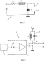
- Such a coil-plug is conventionally modeled by a resonator 1, whose resonant frequency F c is greater than 1 MHz, typically close to 5 MHz.
- the resonator comprises in series a resistor R, an inductance L and a capacitance C. Ignition electrodes 10 and 12 of the coil-plug are connected across the capacitor C.
- the amplitude across the capacitor C is amplified, making it possible to develop multi-filament discharges between the electrodes of the candle, on distances of the order of one centimeter, at high pressure and for peak voltages below 30 kV.
- branched sparks These are referred to as branched sparks, insofar as they involve the simultaneous generation of at least several lines or ionization paths in a given volume, their branches being moreover omnidirectional.
- the control of the supply of such a coil-plug requires the use of a power supply circuit, capable of generating voltage pulses, typically of rise time of 100 ns, and amplitude of the order of 1 kV, at a frequency intended to be very close to the resonant frequency of the radiofrequency resonator of the coil-candle.
- a power supply circuit capable of generating voltage pulses, typically of rise time of 100 ns, and amplitude of the order of 1 kV, at a frequency intended to be very close to the resonant frequency of the radiofrequency resonator of the coil-candle.
- the greater the difference between the resonance frequency of the resonator and the operating frequency of the generator the higher the resonator overvoltage coefficient (ratio between the amplitude of its output voltage and its input voltage) is high.
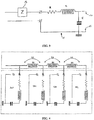
- Such a feed circuit is schematically represented at figure 2 . It conventionally uses a so-called “Class E power amplifier” assembly. This type of DC / AC converter makes it possible to create the voltage pulses with the aforementioned characteristics.
- the amplifier 2 comprises switch M for controlling the switches across the resonator 1, made according to this example in the form of a power MOSFET transistor.
- a control device 5 generates and applies a control signal V1 to a control frequency on the gate of the power MOSFET M, via a control stage 3 shown schematically.
- the latter is activated by the different ignition commands and is in the form of control pulse trains at the control frequency.
- a parallel resonant circuit 4 is connected between an intermediate voltage source Vinter and the drain of the transistor M.
- This circuit 4 comprises an inductance Lp in parallel with a capacitance Cp.
- the parallel resonator transforms the intermediate voltage Vinter into an amplified voltage Va (illustrated in FIG. figure 5 ), corresponding to the intermediate voltage multiplied by the overvoltage coefficient of the parallel resonator.
- This amplified voltage is supplied on the drain of the transistor M, which is also connected to the input of the resonator 1.
- the transistor M therefore acts as a switch and applies (respectively blocks) the voltage Va to the input of the resonator 1 when the control signal V1 is at the logic high (respectively low).
- the transistor M thus imposes a switching frequency, determined by the control signal V1, which is sought to make as close as possible to the resonant frequency of the coil-plug connected at the output (typically 5 MHz), in order to maintain and maximize the energy transfer between the parallel resonator 4 and the series resonator 1 forming the coil-candle.
- This phase of energy transfer from the power stage formed by the amplifier to the resonator of the coil-plug must be performed at the resonance frequency of the resonator, to ensure a good performance. Indeed, if the transistor M imposes a different switching frequency of the resonant frequency of the coil-candle, the energy transfer is degraded, because of the narrow bandwidth of the series resonator used for the candle coil .
- each combustion chamber is equipped with a coil-candle as described above to initiate, on command, combustion.
- the present invention aims to overcome this disadvantage, by allowing to control a plurality of coils-candles through the same and single amplification channel.
- each plasma generating circuit comprises a resonator and each resonator comprises a distinct resonance frequency.
- each plasma generation circuit comprises a resonator, each resonator having an identical resonance frequency, and at least one of the plasma generation circuits further comprises means for shifting the resonance frequency of its resonator.
- the frequency shift means comprise an impedance matching circuit arranged in series between the output of the supply circuit and the resonator.
- the impedance matching circuit comprises an inductance.
- the impedance matching circuit is constituted by an impedant connecting cable ensuring the connection between the output of the supply circuit and each resonator, the length of the portion of cable between the resonators defining the frequency offset. between the resonators.
- each plasma generation circuit is adapted to achieve ignition in one of the following implementations: controlled ignition in a combustion engine cylinder, ignition in a particle filter, ignition decontamination in an air conditioning system.
- the present invention therefore aims at controlling a plurality of coil-type plasma generation circuits, using a single amplification channel, in other words by using a single power supply circuit of the class E power amplifier type as previously described. to the figure 2 , for selectively supplying the plurality of plasma generation circuits connected in parallel at the output of this single supply circuit.
- the principle on which this particular assembly is based consists in exploiting, at the level of the high voltage and high frequency control generated by the supply circuit, the resonance frequency specific to each plasma generation circuit connected at the output of the supply circuit. .
- each of these plasma generating circuits has a resonant frequency well separated from the others. This is indeed to avoid overlapping resonance frequency resonator domains forming each plasma generation circuit and thus to overcome the problems of multiple simultaneous ignitions.
- the resonant frequency difference between the plural plasma generation circuits connected in parallel at the output of the single supply circuit must preferably be at least equal to a multiple of the bandwidth of each resonator. For example, it may be possible to shift the resonance frequency of each plasma generating circuit relative to each other by a value equal to two or three times the bandwidth of each circuit.
- a first way to do this is to use for each plasma generation circuit a coil-candle, as modeled at the figure 1 , different by construction, so that the coils-candles used have sufficiently distinct resonant frequencies in accordance with the principles outlined above.
- each plasma generation circuit consists of a resonator as shown in FIG. figure 1 and where each resonator has a distinct resonant frequency, however, is not optimal for integration into an industrial process.
- a preferred embodiment for carrying out the resonance frequency shift between the plurality of plasma generation circuits to be controlled consists in using identical coil-plugs, the resonators of which model them have identical resonance frequencies, and to associate each resonator means for shifting its resonance frequency.
- the resonance frequency shifting means of a plasma generating circuit comprises an impedance matching circuit 14, arranged to be arranged in series between the output of the supply circuit 2 and the resonator 1.
- the impedance-resonator pair forming the plasma generation circuit has its resonant frequency shifted with respect to the resonance frequency of the resonator 1 of the insulated coil-candle.
- the impedance values of the circuits 14 are thus chosen so that the difference in resonance frequency between each plasma generation circuit, each constituted by an impedance-resonator torque, is equal to at least one multiple of the bandwidth of each resonator.
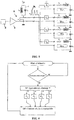
- the resonance frequency shifting means of a plasma generating circuit relative to another use the connecting cable providing the connection between the output of the supply circuit and each coil-candle as series impedance, the coils -bougies are also identical, namely that their resonator have an identical resonant frequency.
- it is the length of the cable portion, respectively L1, L2, L3, between the spark-coils, respectively between BB1 and BB2, between BB2 and BB3 and between BB3 and BB4, which acts as an impedance , in particular of inductance, and thus defines the resonator frequency offset between the resonators of the coils-candles.
- the control method of the single power supply circuit must then take into account the frequency adapted to the channel to be controlled for each ignition.
- control device 5 of the power supply circuit can have a memory capable of preserving the order of frequency classification corresponding to each of the channels to be controlled.
- the control device upon receipt of an ignition request, the control device is firstly able to determine the cylinder to be controlled, numbered for example from 1 to 4 in the order of disposition on the motor. Each cylinder number is therefore associated with the resonance frequency, F1, F2, F3 and F4 respectively, specific to the corresponding plasma generating circuit to be controlled.
- the control device then comprises a module determining the frequency of the control signal to be generated, among these frequencies F1, F2, F3 and F4, as a function of the number of the cylinder to be switched on and the order of classification of the frequencies previously memorized.
- control device applies the control signal to said frequency on an output interface intended to control the switch M.
- the selective power transfer to the plasma generating circuit to be controlled for ignition is then naturally managed by the control frequency used for this ignition.
- the determination of the resonant frequencies to be obtained at the output of the single feed circuit can be controlled by tabulation or servo-control methods as described in the French patent applications filed in the name of the Applicant. FR 05-127669 and FR 05-12770 .
- control device may be provided with an interface for receiving engine operating parameter measurement signals (engine oil temperature, engine torque, engine speed, ignition angle, air temperature). inlet, pressure in the combustion chamber, etc.) and / or power supply operating parameter measurement signals, as well as a particular memory module storing relationships between measurement signals and the frequency of a control signal to be generated.
- engine operating parameter measurement signals engine oil temperature, engine torque, engine speed, ignition angle, air temperature
- power supply operating parameter measurement signals as well as a particular memory module storing relationships between measurement signals and the frequency of a control signal to be generated.
- the controller determines the frequency of a control signal to be generated based on measurement signals received on the receiving interface and relationships stored in the memory module.
Landscapes
- Engineering & Computer Science (AREA)
- Chemical & Material Sciences (AREA)
- Combustion & Propulsion (AREA)
- Mechanical Engineering (AREA)
- General Engineering & Computer Science (AREA)
- Physics & Mathematics (AREA)
- Plasma & Fusion (AREA)
- Optics & Photonics (AREA)
- Ignition Installations For Internal Combustion Engines (AREA)
- Generation Of Surge Voltage And Current (AREA)
- Amplifiers (AREA)
Claims (6)
- Hochfrequenz-Plasmageneratorvorrichtung,
dadurch gekennzeichnet, dass diese umfasst:- eine Versorgungsschaltung (2), umfassend einen Unterbrecher (M), der von einem Steuersignal (V1) gesteuert wird, um eine Zwischenspannung (Vinter) an einen Ausgang der Versorgungsschaltung bei einer Frequenz anzulegen, die durch das Steuersignal definiert wird,- mindestens zwei Plasmageneratorschaltungen (BB1, BB2, BB3, BB4), die parallel am Ausgang der Versorgungsschaltung angeschlossen sind, wobei jede Plasmageneratorschaltung eine Resonanzfrequenz aufweist, die dieser eigen ist und geeignet ist, ein Plasma zu erzeugen, wenn ein hoher Spannungspegel an den Ausgang der Versorgungsschaltung bei einer Frequenz im Wesentlichen gleich der Resonanzfrequenz der Plasmageneratorschaltung angelegt wird,- eine Steuervorrichtung (5) der Versorgungsschaltung, welche die Frequenz des Steuersignals unter einer der Resonanzfrequenzen (F1, F2, F3, F4) der Plasmageneratorschaltungen bestimmt, um selektiv jede Plasmageneratorschaltung gemäß der verwendeten Steuerfrequenz zu steuern,dadurch gekennzeichnet, dass jede Plasmageneratorschaltung einen Resonator (1) umfasst, wobei jeder Resonator eine identische Resonanzfrequenz aufweist, und dadurch, dass mindestens eine der Plasmageneratorschaltungen außerdem Mittel zur Verschiebung der Resonanzfrequenz ihres Resonators umfasst. - Vorrichtung nach Anspruch 1, dadurch gekennzeichnet, dass die Frequenzverschiebungsmittel eine Impedanzanpassungsschaltung (14) umfassen, die in Serie zwischen dem Ausgang der Versorgungsschaltung und dem Resonator angeordnet ist.
- Vorrichtung nach Anspruch 2, dadurch gekennzeichnet, dass die Impedanzanpassungsschaltung eine Induktanz umfasst.
- Vorrichtung nach Anspruch 3, dadurch gekennzeichnet, dass die Impedanzanpassungsschaltung aus einem Impedanzverbindungskabel besteht, das die Verbindung zwischen dem Ausgang der Versorgungsschaltung und jedem Resonator sicherstellt, wobei die Länge (L1, L2, L3) des Kabelabschnitts zwischen den Resonatoren die Frequenzverschiebung zwischen den Resonatoren definiert.
- Vorrichtung nach einem der vorhergehenden Ansprüche, dadurch gekennzeichnet, dass jede Plasmageneratorschaltung geeignet ist, eine Zündung in einer der folgenden Umsetzungen durchzuführen: eine Zündung, die in einem Verbrennungsmotorzylinder gesteuert wird, eine Zündung in einem Partikelfilter, eine Dekontaminationszündung in einem Klimatisierungssystem.
- Verfahren zur Steuerung der Versorgung einer Plasmageneratorvorrichtung, umfassend eine Versorgungsschaltung (2), die einen Unterbrecher (M) aufweist, der von einem Steuersignal (V1) gesteuert wird, um eine Zwischenspannung (Vinter) bei einer Frequenz, die durch das Steuersignal definiert wird, an einen Ausgang der Versorgungsschaltung anzulegen, an den mindestens zwei Plasmageneratorschaltungen parallel angeschlossen sind, wobei jede Plasmageneratorschaltung einen Resonator (1) umfasst, wobei jeder Resonator eine identische Resonanzfrequenz aufweist, wobei mindestens eine der Plasmageneratorschaltungen außerdem Mittel zur Verschiebung der Resonanzfrequenz ihres Resonators umfasst, wobei jede Plasmageneratorschaltung bereitgestellt ist, um selektiv bei einer Resonanzfrequenz gesteuert zu werden, die ihr eigen ist,
wobei das Verfahren die Schritte umfasst:- Empfangen einer Anforderung zur Bestimmung einer Steuerfrequenz;- Bestimmen der zu steuernden Plasmageneratorschaltung;- Bestimmen einer Steuerfrequenz im Wesentlichen gleich der Resonanzfrequenz der zu steuernden Plasmageneratorschaltung;- Generieren des Steuersignals bei der bestimmten Steuerfrequenz.
Applications Claiming Priority (2)
| Application Number | Priority Date | Filing Date | Title |
|---|---|---|---|
| FR0701499A FR2913298B1 (fr) | 2007-03-01 | 2007-03-01 | Pilotage d'une pluralite de bobines bougies via un unique etage de puissance |
| PCT/FR2008/050310 WO2008113955A1 (fr) | 2007-03-01 | 2008-02-25 | Pilotage d'une pluralite de bobines bougies via un unique etage de puissance |
Publications (2)
| Publication Number | Publication Date |
|---|---|
| EP2115296A1 EP2115296A1 (de) | 2009-11-11 |
| EP2115296B1 true EP2115296B1 (de) | 2017-09-06 |
Family
ID=38566150
Family Applications (1)
| Application Number | Title | Priority Date | Filing Date |
|---|---|---|---|
| EP08762151.2A Not-in-force EP2115296B1 (de) | 2007-03-01 | 2008-02-25 | Steuerung mehrerer steckerspulen über eine einzelne leistungsstufe |
Country Status (9)
| Country | Link |
|---|---|
| US (1) | US8547020B2 (de) |
| EP (1) | EP2115296B1 (de) |
| JP (1) | JP5036830B2 (de) |
| KR (1) | KR20090115947A (de) |
| CN (1) | CN101622442B (de) |
| BR (1) | BRPI0807707A2 (de) |
| FR (1) | FR2913298B1 (de) |
| RU (1) | RU2009136346A (de) |
| WO (1) | WO2008113955A1 (de) |
Families Citing this family (19)
| Publication number | Priority date | Publication date | Assignee | Title |
|---|---|---|---|---|
| FR2934942B1 (fr) * | 2008-08-05 | 2010-09-10 | Renault Sas | Controle de la frequence d'excitation d'une bougie radiofrequence. |
| DE102010015344B4 (de) * | 2010-04-17 | 2013-07-25 | Borgwarner Beru Systems Gmbh | Verfahren zum Zünden eines Brennstoff-Luft-Gemisches einer Verbrennungskammer, insbesondere in einem Verbrennungsmotor durch Erzeugen einer Korona-Entladung |
| DE102011052096B4 (de) * | 2010-09-04 | 2019-11-28 | Borgwarner Ludwigsburg Gmbh | Verfahren zum Erregen eines HF-Schwingkreises, welcher als Bestandteil einen Zünder zum Zünden eines Brennstoff-Luft-Gemisches in einer Verbrennungskammer hat |
| JP2012159033A (ja) * | 2011-01-31 | 2012-08-23 | Imagineering Inc | エンジン |
| WO2012161231A1 (ja) * | 2011-05-24 | 2012-11-29 | イマジニアリング株式会社 | 電磁波放射装置 |
| DE202012004602U1 (de) * | 2012-05-08 | 2013-08-12 | Rosenberger Hochfrequenztechnik Gmbh & Co. Kg | Hochfrequenz-Plasmazündvorrichtung |
| CN104426411B (zh) * | 2013-08-28 | 2018-02-23 | 贵阳帕斯玛环保技术有限公司 | 一种单谐振高频高压电源 |
| US9716371B2 (en) | 2013-12-12 | 2017-07-25 | Federal-Mogul Ignition Company | Non-invasive method for resonant frequency detection in corona ignition systems |
| US9525274B2 (en) | 2014-04-29 | 2016-12-20 | Federal-Mogul Ignition Company | Distribution of corona igniter power signal |
| US9531167B2 (en) | 2014-06-02 | 2016-12-27 | Nxp Usa, Inc. | Device and method for connecting an RF generator to a coaxial conductor |
| JP6190793B2 (ja) * | 2014-11-13 | 2017-08-30 | 三菱電機株式会社 | 内燃機関用点火装置 |
| US9518555B2 (en) * | 2014-12-04 | 2016-12-13 | Freescale Semiconductor, Inc. | Radiation devices |
| JPWO2016108283A1 (ja) * | 2014-12-29 | 2017-11-02 | イマジニアリング株式会社 | 点火システム、及び内燃機関 |
| JP6449736B2 (ja) * | 2015-08-05 | 2019-01-09 | 三菱電機株式会社 | 内燃機関点火装置 |
| AT518968B1 (de) | 2016-07-08 | 2019-05-15 | Ge Jenbacher Gmbh & Co Og | Steuervorrichtung für eine Vielzahl von Aktuatoren einer Brennkraftmaschine |
| JP2018025190A (ja) * | 2016-08-09 | 2018-02-15 | サンケン電気株式会社 | 点火装置 |
| WO2018225169A1 (ja) * | 2017-06-07 | 2018-12-13 | イマジニアリング株式会社 | 点火装置 |
| NL2022938B1 (en) * | 2019-04-12 | 2020-10-20 | Vitalfluid B V | Plasma activated fluid processing system |
| CN116982138A (zh) * | 2021-12-31 | 2023-10-31 | 源多可股份有限公司 | 用于多工作站的等离子体处理系统 |
Citations (2)
| Publication number | Priority date | Publication date | Assignee | Title |
|---|---|---|---|---|
| US5655210A (en) * | 1994-08-25 | 1997-08-05 | Hughes Aircraft Company | Corona source for producing corona discharge and fluid waste treatment with corona discharge |
| US20060132360A1 (en) * | 2004-10-15 | 2006-06-22 | Caimi Frank M | Method and apparatus for adaptively controlling antenna parameters to enhance efficiency and maintain antenna size compactness |
Family Cites Families (12)
| Publication number | Priority date | Publication date | Assignee | Title |
|---|---|---|---|---|
| US4317068A (en) * | 1979-10-01 | 1982-02-23 | Combustion Electromagnetics, Inc. | Plasma jet ignition system |
| JPS5859376A (ja) * | 1981-10-05 | 1983-04-08 | Nissan Motor Co Ltd | プラズマ点火装置 |
| EP0228840B1 (de) * | 1986-01-07 | 1991-07-17 | LUCAS INDUSTRIES public limited company | Impuls-Erzeuger-Schaltung für Zündsysteme |
| US5587630A (en) * | 1993-10-28 | 1996-12-24 | Pratt & Whitney Canada Inc. | Continuous plasma ignition system |
| DE19953710B4 (de) * | 1999-11-08 | 2010-06-17 | Robert Bosch Gmbh | Verfahren und Vorrichtung zur Meßfenster-Positionierung für die Ionenstrommessung |
| DE10331418A1 (de) * | 2003-07-10 | 2005-01-27 | Bayerische Motoren Werke Ag | Plasmastrahl-Zündkerze |
| FR2859869B1 (fr) * | 2003-09-12 | 2006-01-20 | Renault Sa | Systeme de generation de plasma. |
| DE102005036968A1 (de) * | 2005-08-05 | 2007-02-15 | Siemens Ag | Plasma-Zündsystem und Verfahren zu dessen Betrieb |
| JP2007221252A (ja) * | 2006-02-14 | 2007-08-30 | General Res Of Electronics Inc | 受信機入力回路 |
| FR2913299B1 (fr) * | 2007-03-01 | 2009-04-17 | Renault Sas | Pilotage d'une pluralite de bobines bougies via un unique etage de puissance. |
| FR2913297B1 (fr) * | 2007-03-01 | 2014-06-20 | Renault Sas | Optimisation de la generation d'une etincelle d'allumage radio-frequence |
| US8104444B2 (en) * | 2007-10-31 | 2012-01-31 | Caterpillar Inc. | Pre-chamber igniter having RF-aided spark initiation |
-
2007
- 2007-03-01 FR FR0701499A patent/FR2913298B1/fr not_active Expired - Fee Related
-
2008
- 2008-02-25 JP JP2009551244A patent/JP5036830B2/ja not_active Expired - Fee Related
- 2008-02-25 US US12/529,417 patent/US8547020B2/en not_active Expired - Fee Related
- 2008-02-25 BR BRPI0807707-0A patent/BRPI0807707A2/pt not_active IP Right Cessation
- 2008-02-25 EP EP08762151.2A patent/EP2115296B1/de not_active Not-in-force
- 2008-02-25 WO PCT/FR2008/050310 patent/WO2008113955A1/fr not_active Ceased
- 2008-02-25 RU RU2009136346/06A patent/RU2009136346A/ru not_active Application Discontinuation
- 2008-02-25 CN CN2008800066976A patent/CN101622442B/zh not_active Expired - Fee Related
- 2008-02-25 KR KR1020097018199A patent/KR20090115947A/ko not_active Withdrawn
Patent Citations (2)
| Publication number | Priority date | Publication date | Assignee | Title |
|---|---|---|---|---|
| US5655210A (en) * | 1994-08-25 | 1997-08-05 | Hughes Aircraft Company | Corona source for producing corona discharge and fluid waste treatment with corona discharge |
| US20060132360A1 (en) * | 2004-10-15 | 2006-06-22 | Caimi Frank M | Method and apparatus for adaptively controlling antenna parameters to enhance efficiency and maintain antenna size compactness |
Also Published As
| Publication number | Publication date |
|---|---|
| CN101622442A (zh) | 2010-01-06 |
| US20100194279A1 (en) | 2010-08-05 |
| BRPI0807707A2 (pt) | 2014-05-27 |
| KR20090115947A (ko) | 2009-11-10 |
| EP2115296A1 (de) | 2009-11-11 |
| CN101622442B (zh) | 2011-12-28 |
| JP2010520399A (ja) | 2010-06-10 |
| WO2008113955A1 (fr) | 2008-09-25 |
| FR2913298B1 (fr) | 2009-04-17 |
| JP5036830B2 (ja) | 2012-09-26 |
| RU2009136346A (ru) | 2011-04-10 |
| US8547020B2 (en) | 2013-10-01 |
| FR2913298A1 (fr) | 2008-09-05 |
Similar Documents
| Publication | Publication Date | Title |
|---|---|---|
| EP2115296B1 (de) | Steuerung mehrerer steckerspulen über eine einzelne leistungsstufe | |
| FR2913299A1 (fr) | Pilotage d'une pluralite de bobines bougies via un unique etage de puissance. | |
| EP2134959B1 (de) | Optimale steuerung der resonanzfrequenz eines resonators in einem funkfrequenzzündsystem | |
| EP2126341B1 (de) | Optimierte erzeugung eines funkfrequenzzündungsfunken | |
| EP2153056B1 (de) | Messvorrichtung in einem funkfrequenzentzündungssystem für einen verbrennungsmotor | |
| EP2205858B1 (de) | Vorrichtung zur messung des ionisationsstromes in einem radiofrequenz-zündsystem für einen brennkraftmotor | |
| EP2315932B1 (de) | Überwachung der erregungsfrequenz einer hochfrequenzzündkerze | |
| EP1961279B1 (de) | Optimierung der erregungsfrequenz eines resonators | |
| EP2250366B1 (de) | Optimierung der erregungsfrequenz einer funkfrequenz-zündkerze | |
| EP2321524B1 (de) | Vorrichtung zum messen des ionisierungsstroms in einem hochfrequenzzündsystem für einen verbrennungsmotor | |
| EP2156160A1 (de) | Diagnose des verschmutzungszustandes von zündkerzen in einem funkfrequenzzündungssystem | |
| EP1446843A2 (de) | Elektronische steuervorrichtung für einen piezoelektrischen ultraschallaktuator und deren betriebsverfahren | |
| FR3047573A1 (fr) | Procede de commande en tension d'un equipement monte dans un vehicule automobile | |
| FR2946190A1 (fr) | Procede de detection du type d'etincelle generee par une bobine-bougie d'allumage radiofrequence, et dispositif correspondant. | |
| WO2012160317A1 (fr) | Alimentation pour allumage radiofrequence avec amplificateur a double etage | |
| EP1420156A2 (de) | Ansteuerschaltung für Kraftstoffinjektoren eines Fahrzeugs | |
| FR2920633A1 (fr) | Procede de commande de la puissance moyenne dissipee par une lampe dans un vehicule automobile | |
| FR2476755A1 (fr) | Systeme d'allumage pour des moteurs a combustion interne | |
| EP0171523A2 (de) | Elektronische Einrichtung, auf einen Benzin oder Gas brauchenden Kraftfahrzeug, zu montieren bestimmt | |
| FR2920613A1 (fr) | Dispositif de commande d'un transistor haute tension |
Legal Events
| Date | Code | Title | Description |
|---|---|---|---|
| PUAI | Public reference made under article 153(3) epc to a published international application that has entered the european phase |
Free format text: ORIGINAL CODE: 0009012 |
|
| 17P | Request for examination filed |
Effective date: 20090730 |
|
| AK | Designated contracting states |
Kind code of ref document: A1 Designated state(s): AT BE BG CH CY CZ DE DK EE ES FI FR GB GR HR HU IE IS IT LI LT LU LV MC MT NL NO PL PT RO SE SI SK TR |
|
| DAX | Request for extension of the european patent (deleted) | ||
| 17Q | First examination report despatched |
Effective date: 20160613 |
|
| GRAP | Despatch of communication of intention to grant a patent |
Free format text: ORIGINAL CODE: EPIDOSNIGR1 |
|
| INTG | Intention to grant announced |
Effective date: 20170301 |
|
| GRAS | Grant fee paid |
Free format text: ORIGINAL CODE: EPIDOSNIGR3 |
|
| GRAA | (expected) grant |
Free format text: ORIGINAL CODE: 0009210 |
|
| AK | Designated contracting states |
Kind code of ref document: B1 Designated state(s): AT BE BG CH CY CZ DE DK EE ES FI FR GB GR HR HU IE IS IT LI LT LU LV MC MT NL NO PL PT RO SE SI SK TR |
|
| REG | Reference to a national code |
Ref country code: GB Ref legal event code: FG4D Free format text: NOT ENGLISH |
|
| REG | Reference to a national code |
Ref country code: CH Ref legal event code: EP Ref country code: AT Ref legal event code: REF Ref document number: 926189 Country of ref document: AT Kind code of ref document: T Effective date: 20170915 |
|
| REG | Reference to a national code |
Ref country code: IE Ref legal event code: FG4D Free format text: LANGUAGE OF EP DOCUMENT: FRENCH |
|
| REG | Reference to a national code |
Ref country code: DE Ref legal event code: R096 Ref document number: 602008052022 Country of ref document: DE |
|
| REG | Reference to a national code |
Ref country code: NL Ref legal event code: MP Effective date: 20170906 |
|
| REG | Reference to a national code |
Ref country code: LT Ref legal event code: MG4D |
|
| PG25 | Lapsed in a contracting state [announced via postgrant information from national office to epo] |
Ref country code: HR Free format text: LAPSE BECAUSE OF FAILURE TO SUBMIT A TRANSLATION OF THE DESCRIPTION OR TO PAY THE FEE WITHIN THE PRESCRIBED TIME-LIMIT Effective date: 20170906 Ref country code: LT Free format text: LAPSE BECAUSE OF FAILURE TO SUBMIT A TRANSLATION OF THE DESCRIPTION OR TO PAY THE FEE WITHIN THE PRESCRIBED TIME-LIMIT Effective date: 20170906 Ref country code: FI Free format text: LAPSE BECAUSE OF FAILURE TO SUBMIT A TRANSLATION OF THE DESCRIPTION OR TO PAY THE FEE WITHIN THE PRESCRIBED TIME-LIMIT Effective date: 20170906 Ref country code: NO Free format text: LAPSE BECAUSE OF FAILURE TO SUBMIT A TRANSLATION OF THE DESCRIPTION OR TO PAY THE FEE WITHIN THE PRESCRIBED TIME-LIMIT Effective date: 20171206 Ref country code: SE Free format text: LAPSE BECAUSE OF FAILURE TO SUBMIT A TRANSLATION OF THE DESCRIPTION OR TO PAY THE FEE WITHIN THE PRESCRIBED TIME-LIMIT Effective date: 20170906 |
|
| REG | Reference to a national code |
Ref country code: AT Ref legal event code: MK05 Ref document number: 926189 Country of ref document: AT Kind code of ref document: T Effective date: 20170906 |
|
| REG | Reference to a national code |
Ref country code: FR Ref legal event code: PLFP Year of fee payment: 11 |
|
| PG25 | Lapsed in a contracting state [announced via postgrant information from national office to epo] |
Ref country code: LV Free format text: LAPSE BECAUSE OF FAILURE TO SUBMIT A TRANSLATION OF THE DESCRIPTION OR TO PAY THE FEE WITHIN THE PRESCRIBED TIME-LIMIT Effective date: 20170906 Ref country code: ES Free format text: LAPSE BECAUSE OF FAILURE TO SUBMIT A TRANSLATION OF THE DESCRIPTION OR TO PAY THE FEE WITHIN THE PRESCRIBED TIME-LIMIT Effective date: 20170906 Ref country code: BG Free format text: LAPSE BECAUSE OF FAILURE TO SUBMIT A TRANSLATION OF THE DESCRIPTION OR TO PAY THE FEE WITHIN THE PRESCRIBED TIME-LIMIT Effective date: 20171206 Ref country code: GR Free format text: LAPSE BECAUSE OF FAILURE TO SUBMIT A TRANSLATION OF THE DESCRIPTION OR TO PAY THE FEE WITHIN THE PRESCRIBED TIME-LIMIT Effective date: 20171207 |
|
| PG25 | Lapsed in a contracting state [announced via postgrant information from national office to epo] |
Ref country code: NL Free format text: LAPSE BECAUSE OF FAILURE TO SUBMIT A TRANSLATION OF THE DESCRIPTION OR TO PAY THE FEE WITHIN THE PRESCRIBED TIME-LIMIT Effective date: 20170906 |
|
| PG25 | Lapsed in a contracting state [announced via postgrant information from national office to epo] |
Ref country code: RO Free format text: LAPSE BECAUSE OF FAILURE TO SUBMIT A TRANSLATION OF THE DESCRIPTION OR TO PAY THE FEE WITHIN THE PRESCRIBED TIME-LIMIT Effective date: 20170906 Ref country code: CZ Free format text: LAPSE BECAUSE OF FAILURE TO SUBMIT A TRANSLATION OF THE DESCRIPTION OR TO PAY THE FEE WITHIN THE PRESCRIBED TIME-LIMIT Effective date: 20170906 Ref country code: PL Free format text: LAPSE BECAUSE OF FAILURE TO SUBMIT A TRANSLATION OF THE DESCRIPTION OR TO PAY THE FEE WITHIN THE PRESCRIBED TIME-LIMIT Effective date: 20170906 |
|
| PG25 | Lapsed in a contracting state [announced via postgrant information from national office to epo] |
Ref country code: AT Free format text: LAPSE BECAUSE OF FAILURE TO SUBMIT A TRANSLATION OF THE DESCRIPTION OR TO PAY THE FEE WITHIN THE PRESCRIBED TIME-LIMIT Effective date: 20170906 Ref country code: IS Free format text: LAPSE BECAUSE OF FAILURE TO SUBMIT A TRANSLATION OF THE DESCRIPTION OR TO PAY THE FEE WITHIN THE PRESCRIBED TIME-LIMIT Effective date: 20180106 Ref country code: SK Free format text: LAPSE BECAUSE OF FAILURE TO SUBMIT A TRANSLATION OF THE DESCRIPTION OR TO PAY THE FEE WITHIN THE PRESCRIBED TIME-LIMIT Effective date: 20170906 Ref country code: EE Free format text: LAPSE BECAUSE OF FAILURE TO SUBMIT A TRANSLATION OF THE DESCRIPTION OR TO PAY THE FEE WITHIN THE PRESCRIBED TIME-LIMIT Effective date: 20170906 Ref country code: IT Free format text: LAPSE BECAUSE OF FAILURE TO SUBMIT A TRANSLATION OF THE DESCRIPTION OR TO PAY THE FEE WITHIN THE PRESCRIBED TIME-LIMIT Effective date: 20170906 |
|
| REG | Reference to a national code |
Ref country code: DE Ref legal event code: R097 Ref document number: 602008052022 Country of ref document: DE |
|
| PLBE | No opposition filed within time limit |
Free format text: ORIGINAL CODE: 0009261 |
|
| STAA | Information on the status of an ep patent application or granted ep patent |
Free format text: STATUS: NO OPPOSITION FILED WITHIN TIME LIMIT |
|
| PG25 | Lapsed in a contracting state [announced via postgrant information from national office to epo] |
Ref country code: DK Free format text: LAPSE BECAUSE OF FAILURE TO SUBMIT A TRANSLATION OF THE DESCRIPTION OR TO PAY THE FEE WITHIN THE PRESCRIBED TIME-LIMIT Effective date: 20170906 |
|
| 26N | No opposition filed |
Effective date: 20180607 |
|
| PG25 | Lapsed in a contracting state [announced via postgrant information from national office to epo] |
Ref country code: SI Free format text: LAPSE BECAUSE OF FAILURE TO SUBMIT A TRANSLATION OF THE DESCRIPTION OR TO PAY THE FEE WITHIN THE PRESCRIBED TIME-LIMIT Effective date: 20170906 |
|
| REG | Reference to a national code |
Ref country code: CH Ref legal event code: PL |
|
| PG25 | Lapsed in a contracting state [announced via postgrant information from national office to epo] |
Ref country code: MT Free format text: LAPSE BECAUSE OF FAILURE TO SUBMIT A TRANSLATION OF THE DESCRIPTION OR TO PAY THE FEE WITHIN THE PRESCRIBED TIME-LIMIT Effective date: 20170906 Ref country code: MC Free format text: LAPSE BECAUSE OF FAILURE TO SUBMIT A TRANSLATION OF THE DESCRIPTION OR TO PAY THE FEE WITHIN THE PRESCRIBED TIME-LIMIT Effective date: 20170906 |
|
| GBPC | Gb: european patent ceased through non-payment of renewal fee |
Effective date: 20180225 |
|
| REG | Reference to a national code |
Ref country code: IE Ref legal event code: MM4A |
|
| REG | Reference to a national code |
Ref country code: BE Ref legal event code: MM Effective date: 20180228 |
|
| PG25 | Lapsed in a contracting state [announced via postgrant information from national office to epo] |
Ref country code: LU Free format text: LAPSE BECAUSE OF NON-PAYMENT OF DUE FEES Effective date: 20180225 Ref country code: LI Free format text: LAPSE BECAUSE OF NON-PAYMENT OF DUE FEES Effective date: 20180228 Ref country code: CH Free format text: LAPSE BECAUSE OF NON-PAYMENT OF DUE FEES Effective date: 20180228 |
|
| PG25 | Lapsed in a contracting state [announced via postgrant information from national office to epo] |
Ref country code: IE Free format text: LAPSE BECAUSE OF NON-PAYMENT OF DUE FEES Effective date: 20180225 |
|
| PG25 | Lapsed in a contracting state [announced via postgrant information from national office to epo] |
Ref country code: BE Free format text: LAPSE BECAUSE OF NON-PAYMENT OF DUE FEES Effective date: 20180228 Ref country code: GB Free format text: LAPSE BECAUSE OF NON-PAYMENT OF DUE FEES Effective date: 20180225 |
|
| PG25 | Lapsed in a contracting state [announced via postgrant information from national office to epo] |
Ref country code: TR Free format text: LAPSE BECAUSE OF FAILURE TO SUBMIT A TRANSLATION OF THE DESCRIPTION OR TO PAY THE FEE WITHIN THE PRESCRIBED TIME-LIMIT Effective date: 20170906 |
|
| PG25 | Lapsed in a contracting state [announced via postgrant information from national office to epo] |
Ref country code: HU Free format text: LAPSE BECAUSE OF FAILURE TO SUBMIT A TRANSLATION OF THE DESCRIPTION OR TO PAY THE FEE WITHIN THE PRESCRIBED TIME-LIMIT; INVALID AB INITIO Effective date: 20080225 Ref country code: PT Free format text: LAPSE BECAUSE OF FAILURE TO SUBMIT A TRANSLATION OF THE DESCRIPTION OR TO PAY THE FEE WITHIN THE PRESCRIBED TIME-LIMIT Effective date: 20170906 |
|
| PG25 | Lapsed in a contracting state [announced via postgrant information from national office to epo] |
Ref country code: CY Free format text: LAPSE BECAUSE OF FAILURE TO SUBMIT A TRANSLATION OF THE DESCRIPTION OR TO PAY THE FEE WITHIN THE PRESCRIBED TIME-LIMIT Effective date: 20170906 |
|
| PGFP | Annual fee paid to national office [announced via postgrant information from national office to epo] |
Ref country code: DE Payment date: 20220217 Year of fee payment: 15 |
|
| PGFP | Annual fee paid to national office [announced via postgrant information from national office to epo] |
Ref country code: FR Payment date: 20220217 Year of fee payment: 15 |
|
| REG | Reference to a national code |
Ref country code: DE Ref legal event code: R119 Ref document number: 602008052022 Country of ref document: DE |
|
| PG25 | Lapsed in a contracting state [announced via postgrant information from national office to epo] |
Ref country code: FR Free format text: LAPSE BECAUSE OF NON-PAYMENT OF DUE FEES Effective date: 20230228 Ref country code: DE Free format text: LAPSE BECAUSE OF NON-PAYMENT OF DUE FEES Effective date: 20230901 |