EP2114627B1 - Laborsystem mit einer transporteinrichtung für proben und einem überwachungssystem zur einhaltung eines sicherheitsabstandes - Google Patents
Laborsystem mit einer transporteinrichtung für proben und einem überwachungssystem zur einhaltung eines sicherheitsabstandes Download PDFInfo
- Publication number
- EP2114627B1 EP2114627B1 EP08804565A EP08804565A EP2114627B1 EP 2114627 B1 EP2114627 B1 EP 2114627B1 EP 08804565 A EP08804565 A EP 08804565A EP 08804565 A EP08804565 A EP 08804565A EP 2114627 B1 EP2114627 B1 EP 2114627B1
- Authority
- EP
- European Patent Office
- Prior art keywords
- transport
- handling
- samples
- laboratory
- treatment
- Prior art date
- Legal status (The legal status is an assumption and is not a legal conclusion. Google has not performed a legal analysis and makes no representation as to the accuracy of the status listed.)
- Not-in-force
Links
- 238000012544 monitoring process Methods 0.000 title claims abstract description 19
- 238000012545 processing Methods 0.000 claims abstract description 7
- 238000012806 monitoring device Methods 0.000 claims description 12
- 238000004458 analytical method Methods 0.000 claims description 4
- 239000004568 cement Substances 0.000 claims description 3
- 238000004519 manufacturing process Methods 0.000 claims description 3
- 229910052500 inorganic mineral Inorganic materials 0.000 claims description 2
- 239000011707 mineral Substances 0.000 claims description 2
- 238000012546 transfer Methods 0.000 abstract description 6
- 239000000523 sample Substances 0.000 description 41
- 230000004888 barrier function Effects 0.000 description 9
- 229910000831 Steel Inorganic materials 0.000 description 8
- 239000010959 steel Substances 0.000 description 8
- 238000000034 method Methods 0.000 description 6
- 230000033001 locomotion Effects 0.000 description 5
- 230000008569 process Effects 0.000 description 4
- 238000011156 evaluation Methods 0.000 description 3
- 238000005259 measurement Methods 0.000 description 3
- 230000001681 protective effect Effects 0.000 description 3
- 238000004891 communication Methods 0.000 description 2
- 230000008878 coupling Effects 0.000 description 2
- 238000010168 coupling process Methods 0.000 description 2
- 238000005859 coupling reaction Methods 0.000 description 2
- 238000009434 installation Methods 0.000 description 2
- 230000006855 networking Effects 0.000 description 2
- 230000003068 static effect Effects 0.000 description 2
- 241000233866 Fungi Species 0.000 description 1
- 230000001133 acceleration Effects 0.000 description 1
- 230000009471 action Effects 0.000 description 1
- 238000013459 approach Methods 0.000 description 1
- 230000031018 biological processes and functions Effects 0.000 description 1
- 239000003990 capacitor Substances 0.000 description 1
- 230000001419 dependent effect Effects 0.000 description 1
- 238000013461 design Methods 0.000 description 1
- 238000010586 diagram Methods 0.000 description 1
- 238000010191 image analysis Methods 0.000 description 1
- 230000003993 interaction Effects 0.000 description 1
- 239000007788 liquid Substances 0.000 description 1
- 239000000463 material Substances 0.000 description 1
- 230000005693 optoelectronics Effects 0.000 description 1
- 239000000126 substance Substances 0.000 description 1
- 230000001960 triggered effect Effects 0.000 description 1
- 230000000007 visual effect Effects 0.000 description 1
Images



Classifications
-
- B—PERFORMING OPERATIONS; TRANSPORTING
- B25—HAND TOOLS; PORTABLE POWER-DRIVEN TOOLS; MANIPULATORS
- B25J—MANIPULATORS; CHAMBERS PROVIDED WITH MANIPULATION DEVICES
- B25J19/00—Accessories fitted to manipulators, e.g. for monitoring, for viewing; Safety devices combined with or specially adapted for use in connection with manipulators
- B25J19/06—Safety devices
-
- B—PERFORMING OPERATIONS; TRANSPORTING
- B25—HAND TOOLS; PORTABLE POWER-DRIVEN TOOLS; MANIPULATORS
- B25J—MANIPULATORS; CHAMBERS PROVIDED WITH MANIPULATION DEVICES
- B25J5/00—Manipulators mounted on wheels or on carriages
- B25J5/02—Manipulators mounted on wheels or on carriages travelling along a guideway
-
- F—MECHANICAL ENGINEERING; LIGHTING; HEATING; WEAPONS; BLASTING
- F16—ENGINEERING ELEMENTS AND UNITS; GENERAL MEASURES FOR PRODUCING AND MAINTAINING EFFECTIVE FUNCTIONING OF MACHINES OR INSTALLATIONS; THERMAL INSULATION IN GENERAL
- F16P—SAFETY DEVICES IN GENERAL; SAFETY DEVICES FOR PRESSES
- F16P3/00—Safety devices acting in conjunction with the control or operation of a machine; Control arrangements requiring the simultaneous use of two or more parts of the body
- F16P3/12—Safety devices acting in conjunction with the control or operation of a machine; Control arrangements requiring the simultaneous use of two or more parts of the body with means, e.g. feelers, which in case of the presence of a body part of a person in or near the danger zone influence the control or operation of the machine
- F16P3/14—Safety devices acting in conjunction with the control or operation of a machine; Control arrangements requiring the simultaneous use of two or more parts of the body with means, e.g. feelers, which in case of the presence of a body part of a person in or near the danger zone influence the control or operation of the machine the means being photocells or other devices sensitive without mechanical contact
-
- F—MECHANICAL ENGINEERING; LIGHTING; HEATING; WEAPONS; BLASTING
- F16—ENGINEERING ELEMENTS AND UNITS; GENERAL MEASURES FOR PRODUCING AND MAINTAINING EFFECTIVE FUNCTIONING OF MACHINES OR INSTALLATIONS; THERMAL INSULATION IN GENERAL
- F16P—SAFETY DEVICES IN GENERAL; SAFETY DEVICES FOR PRESSES
- F16P3/00—Safety devices acting in conjunction with the control or operation of a machine; Control arrangements requiring the simultaneous use of two or more parts of the body
- F16P3/12—Safety devices acting in conjunction with the control or operation of a machine; Control arrangements requiring the simultaneous use of two or more parts of the body with means, e.g. feelers, which in case of the presence of a body part of a person in or near the danger zone influence the control or operation of the machine
- F16P3/14—Safety devices acting in conjunction with the control or operation of a machine; Control arrangements requiring the simultaneous use of two or more parts of the body with means, e.g. feelers, which in case of the presence of a body part of a person in or near the danger zone influence the control or operation of the machine the means being photocells or other devices sensitive without mechanical contact
- F16P3/142—Safety devices acting in conjunction with the control or operation of a machine; Control arrangements requiring the simultaneous use of two or more parts of the body with means, e.g. feelers, which in case of the presence of a body part of a person in or near the danger zone influence the control or operation of the machine the means being photocells or other devices sensitive without mechanical contact using image capturing devices
-
- F—MECHANICAL ENGINEERING; LIGHTING; HEATING; WEAPONS; BLASTING
- F16—ENGINEERING ELEMENTS AND UNITS; GENERAL MEASURES FOR PRODUCING AND MAINTAINING EFFECTIVE FUNCTIONING OF MACHINES OR INSTALLATIONS; THERMAL INSULATION IN GENERAL
- F16P—SAFETY DEVICES IN GENERAL; SAFETY DEVICES FOR PRESSES
- F16P3/00—Safety devices acting in conjunction with the control or operation of a machine; Control arrangements requiring the simultaneous use of two or more parts of the body
- F16P3/12—Safety devices acting in conjunction with the control or operation of a machine; Control arrangements requiring the simultaneous use of two or more parts of the body with means, e.g. feelers, which in case of the presence of a body part of a person in or near the danger zone influence the control or operation of the machine
- F16P3/14—Safety devices acting in conjunction with the control or operation of a machine; Control arrangements requiring the simultaneous use of two or more parts of the body with means, e.g. feelers, which in case of the presence of a body part of a person in or near the danger zone influence the control or operation of the machine the means being photocells or other devices sensitive without mechanical contact
- F16P3/147—Safety devices acting in conjunction with the control or operation of a machine; Control arrangements requiring the simultaneous use of two or more parts of the body with means, e.g. feelers, which in case of the presence of a body part of a person in or near the danger zone influence the control or operation of the machine the means being photocells or other devices sensitive without mechanical contact using electro-magnetic technology, e.g. tags or radar
-
- G—PHYSICS
- G01—MEASURING; TESTING
- G01N—INVESTIGATING OR ANALYSING MATERIALS BY DETERMINING THEIR CHEMICAL OR PHYSICAL PROPERTIES
- G01N35/00—Automatic analysis not limited to methods or materials provided for in any single one of groups G01N1/00 - G01N33/00; Handling materials therefor
- G01N35/02—Automatic analysis not limited to methods or materials provided for in any single one of groups G01N1/00 - G01N33/00; Handling materials therefor using a plurality of sample containers moved by a conveyor system past one or more treatment or analysis stations
- G01N35/04—Details of the conveyor system
-
- G—PHYSICS
- G01—MEASURING; TESTING
- G01N—INVESTIGATING OR ANALYSING MATERIALS BY DETERMINING THEIR CHEMICAL OR PHYSICAL PROPERTIES
- G01N35/00—Automatic analysis not limited to methods or materials provided for in any single one of groups G01N1/00 - G01N33/00; Handling materials therefor
- G01N35/02—Automatic analysis not limited to methods or materials provided for in any single one of groups G01N1/00 - G01N33/00; Handling materials therefor using a plurality of sample containers moved by a conveyor system past one or more treatment or analysis stations
- G01N35/04—Details of the conveyor system
- G01N2035/0401—Sample carriers, cuvettes or reaction vessels
- G01N2035/0406—Individual bottles or tubes
- G01N2035/041—Individual bottles or tubes lifting items out of a rack for access
-
- G—PHYSICS
- G01—MEASURING; TESTING
- G01N—INVESTIGATING OR ANALYSING MATERIALS BY DETERMINING THEIR CHEMICAL OR PHYSICAL PROPERTIES
- G01N35/00—Automatic analysis not limited to methods or materials provided for in any single one of groups G01N1/00 - G01N33/00; Handling materials therefor
- G01N35/02—Automatic analysis not limited to methods or materials provided for in any single one of groups G01N1/00 - G01N33/00; Handling materials therefor using a plurality of sample containers moved by a conveyor system past one or more treatment or analysis stations
- G01N35/04—Details of the conveyor system
- G01N2035/0474—Details of actuating means for conveyors or pipettes
- G01N2035/0479—Details of actuating means for conveyors or pipettes hydraulic or pneumatic
- G01N2035/0481—Pneumatic tube conveyors; Tube mails; "Rohrpost"
-
- G—PHYSICS
- G01—MEASURING; TESTING
- G01N—INVESTIGATING OR ANALYSING MATERIALS BY DETERMINING THEIR CHEMICAL OR PHYSICAL PROPERTIES
- G01N35/00—Automatic analysis not limited to methods or materials provided for in any single one of groups G01N1/00 - G01N33/00; Handling materials therefor
- G01N35/02—Automatic analysis not limited to methods or materials provided for in any single one of groups G01N1/00 - G01N33/00; Handling materials therefor using a plurality of sample containers moved by a conveyor system past one or more treatment or analysis stations
- G01N35/026—Automatic analysis not limited to methods or materials provided for in any single one of groups G01N1/00 - G01N33/00; Handling materials therefor using a plurality of sample containers moved by a conveyor system past one or more treatment or analysis stations having blocks or racks of reaction cells or cuvettes
Definitions
- the invention relates to a laboratory system according to the preamble of claim 1.
- Such a laboratory system is for example from the EP-A-0 633 207 known.
- a laboratory system is known in which the various treatment devices are arranged around a robot arranged in the middle.
- the robot transfers the samples between the treatment facilities and delivers the samples to the individual treatment facilities.
- the samples are usually transported by means of a sample carrier, which is for example a cup or a steel ring.
- the sample material is either loosely in the cup or is pressed into the steel ring.
- the dosage of the sample material from the sample carrier (cup) is also taken over by the robot.
- a central robot is relatively expensive and potentially dangerous to humans because of its long range and kinematics (large forces and accelerations), so that sufficient safety barriers are required.
- the installation possibilities of the individual treatment facilities are limited by the central arrangement of the robot.
- a laboratory system is proposed in which the transport of the samples to the different treatment facilities via a continuously circulating conveyor belt.
- the conveyor belt can be stopped to bring a sample carrier on a treatment device in a predetermined stop position.
- One of the Treatment device associated handling device then causes the transport of a sample carrier from the holding position out to the respective treatment facility and back.
- a laboratory system in which the samples are transported by a self-propelled robot, e.g. equipped with a laser scanner to avoid obstacles.
- sample containers are transported via a belt conveyor to a treatment facility.
- the end positions of a conveyor carriage that can be reached by belt conveyors are monitored by sensors.
- a handling device provided in the region of the treatment device transfers the sample vessels between the conveying carriage and the treatment device.
- Controlling a conveyor by means of computer-aided image recognition is also from the DE 10 2006 015 689 A1 , of the DE 10 2006 002 704 A1 and the DE 10 2005 063 193 A1 known.
- optoelectronic elements are used for position or object recognition in conveyor systems.
- the DE 32 08 901 A1 further discloses a method and a device for preventing accidents between a movable machine and one or more persons in their range of motion, the falling below a minimum distance is detected by transmitter and receiver and by triggering a control signal, the driving and / or working movement of the Work machine is interrupted.
- the DE 295 20 515 U1 describes a transport system in which the carriage for detecting the guideway has a CCD camera.
- the invention has for its object to provide a laboratory system that allows parallel work of man and machine without complex security barriers are required.
- the laboratory system consists essentially of one or more transport means (s) for samples, at least two treatment devices for the preparation, analysis and / or processing of samples, at least one movable handling device for handling the samples in the region of a treatment device, wherein the handling device for the transfer of the sample between the transport device and the treatment device is designed, and a monitoring system accompanying the handling device for maintaining a safety distance.
- the handling device is mounted on the transport device and movable therewith between at least two treatment devices, and the monitoring system is a mitfahrendes with the handling device monitoring system by a camera for generating distance images and / or a location system with at least one transmitter and at least a receiver is formed.
- the receiver of the positioning system is mounted on the movable transport device and is designed such that it generates an alarm signal when the at least one transmitter to be supported by laboratory staff falls below a minimum distance to the receiver.
- the camera will be connected to the Handling device or also attached to the transport device.
- the monitoring system is used when posed by the mounted on the movable transport device handling equipment danger to people.
- the monitoring system which preferably comprises both the camera and the locating system, it is possible for humans and machines to work in parallel in relative proximity to one another, without the need for elaborate safety barriers which limit the freedom of movement.
- the monitoring system further comprises a power and / or power monitoring device which monitors current and / or power values of the handling device.
- At least one treatment device is designed to be movable, whereby the flexibility of the laboratory system can be further increased.
- sample means a sample carrier which comprises, for example, a beaker with sample material, a steel ring with pressed-in sample material, empty cups, empty steel rings and various containers of different sizes for sample material.
- sample material is transported loosely in beakers or containers.
- the sample material is pressed after suitable preparation in a steel ring.
- the handling device can also be designed so that it can carry out the metering of the sample material from the sample carrier, in particular the cup, to a treatment device.
- the transport devices can optionally travel freely or on a given transport route, in particular a rail track, from one location to another.
- the transport routes can run in different rooms and / or on different levels and can be coupled together as desired.
- the handling device is movable together with one or more samples on the transport device. It can also be provided that there are additionally one or more transport devices which transport only one or more samples.
- the transport devices have their own energy supply, in particular a low-voltage system, and can be self-propelled.
- the transport device can supply the handling device or the treatment device to be supported with energy.
- the transport path is modular and can be easily supplemented in any way.
- the transport system comprises at least a first and a vertically offset second transport path, wherein between the first and second transport path a lifting device for the transport devices is provided.
- the treatment facilities can be arranged on different levels or floors. Several routes can run in parallel and be combined as desired.
- the laboratory system shown essentially consists of a transport device 1 for samples 2, a plurality of treatment devices 3 to 9 and at least one handling device 10 for handling the samples 2 in the region of a treatment device.
- sample means a sample carrier which comprises, for example, a beaker with sample material, a steel ring with pressed-in sample material, empty cups, empty steel rings, various containers of different sizes for sample material.
- sample material is transported loosely in beakers or containers.
- the sample material is pressed after suitable preparation in a steel ring.
- the transport devices (for example a shuttle) are either designed to be free-moving or can be moved along a transport path 11, in particular a rail track.
- the handling device 10 can be moved either on the transport path 11 or a second transport path between at least two of the treatment devices 3-9. In the illustrated embodiment, the handling device 10 is movable together with one or more samples 2 on the transport device.
- the handling device 10 is designed for the transfer of the sample 2 between the transport device 1 and one of the treatment devices 3 to 9.
- the handling device 10 may consist, for example, of a correspondingly designed gripping arm 15, which can receive the sample or the sample carrier with the sample material and, if necessary, can also meter the sample material from the sample carrier in the region of a treatment device. The dosage can be done by slowly dumping the sample material.
- means could additionally be provided which excite the gripper 15f of the handling device 10 or of the gripping arm 15 with a high-frequency vibration.
- the laboratory system for the preparation, analysis and / or processing of samples of cement production and / or ore and mineral processing is formed.
- the treatment devices 3 to 9 are, for example, a pneumatic tube receiving station 3, a mill / press 4, 5, a fineness measuring device 6, a spectrometer 7, a diffractometer 8 and a return 9.
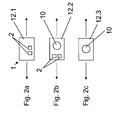
- FIG. 2a-2c Now various embodiments of the transport facilities (shuttle) are shown.
- transport device 1 (12.1) is a pure transport shuttle for one or more Samples 2 designed.
- transport device 12.2 is used in addition to the transport of the samples 2 and the transport of a handling device 10.
- the transport device 12.3 according to Fig. 2c Finally, it is designed as a pure handling shuttle and carries only one handling device 10.
- the transport devices 1 have their own energy supply, in particular a low-voltage system.
- the transport devices can be formed, for example, self-propelled.
- the transport device can supply energy to a handling device or a treatment device (mounted on the transport device).
- the power supply of the transport devices and of the handling device or of the treatment device can, however, also take place via the transport path (for example rail).
- the transport path for the transport devices may be formed as a rail, wherein it is then advantageously constructed modular, so that it can be formed in any shape and extent.
- a first and a vertically offset second transport path could be provided, wherein between the first and the second transport path, a lifting device 14 is provided for the transport devices ( Fig. 1 ). Connections of routes on different levels can thus be realized.
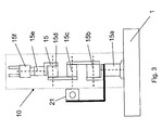
- Figure 3 shows a mounted on a transport device 1 and thus movable handling device 10.
- the handling device is formed here by way of example by a special gripping arm 15.
- a camera 21 attached to the gripper arm for generating distance images is shown here.
- the camera 21 can also be mounted on the movable transport device
- the gripping arm 15 is embodied here as a scalable lightweight arm and has a plurality of rotary and pivoting units 15a, 15b, 15c, 15d and 15e, by means of which reconfigurable, modular robot structures can be realized.
- an electric gripper 15f there is an electric gripper 15f.
- the individual drive modules (grippers and rotary / swivel units) can be freely and flexibly assembled with connecting parts to form an individual lightweight arm in the IP65 protection class.
- the radius of action can be adapted to the application by freely choosing the kinematic structure.
- the rotary and rotary units are moved, for example, by brushless servo motors with harmonic drive gear and already have complete power and control electronics, which allows positioning with ramp control and a Endlagen-, voltage, current and temperature monitoring.
- the compact swivel units achieve a net mass-to-load ratio that is better than 2: 1.
- the power supply, the control options and the universal communication interfaces can already be integrated, so that only one cable is required for drive networking.
- the drive components are equipped with hollow shafts, the wiring can be guided inside and thus protected.
- the 24V DC voltage is sufficient for the operation of the lightweight arm.
- the low energy requirement of the lightweight arm is suitably covered by the electrical system of the transport device.
- the control of the lightweight arm takes place for example via an embedded controller based on a single-board PC. A special robot control (known from industrial robots) is therefore not required.
- the transport device 1 (assembly with handling device 10) also has a monitoring device 20, which in the embodiment according to Fig. 3 is formed by a camera 21 for generating range images.
- the camera 21 may, for example, be a so-called TOF camera (time-of-flight camera).
- TOF camera time-of-flight camera
- the TOF principle is based on the measurement of the light transit time. One emits a light pulse and measures the time it takes the light to return from an object reflected back. In this way, the distance to an object can be determined for each pixel, so that a three-dimensional structure of the scene is obtained.
- the treatment stations are approached by the transport device, wherein the closer environment of the respective treatment station is captured by the camera and a pattern is generated.
- the image acquisition takes place at each treatment station, so that the working environments for the handling device are recorded and learned.
- the respective image acquisition initially takes place without intervention on the devices by operating personnel (so-called static image acquisition).
- the camera can also be moved to record the complete environment. If the camera is attached to the handling device, it is automatically aligned in the working direction of the handling device.
- the treatment stations are approached arbitrarily by the transport devices.
- the laboratory staff may work in the same room with the treatment stations.
- the devices are usually in the service or manual mode connected. Since it can not be ruled out that the personnel will also reach into the working space of the handling unit or be there, this working space is monitored by the camera.
- new image information is generated sufficiently quickly and compared with the recorded static image. Deviations from the original images, for example when persons enter the surveillance area, are detected quickly enough and lead to the shutdown of the handling device.
- the monitoring device 20 in addition to the camera 21, an evaluation circuit 22 which cooperates with a shutdown circuit 23 to turn off the handling device 10 when a predetermined safety distance is exceeded.
- a location system with at least one transmitter and at least one receiver can be provided (see Fig. 5 ).
- a receiver 25 is attached to the movable transport device 1 and designed such that it generates an alarm signal when at least one transmitter 26 is below a minimum distance to the receiver.
- the location system provides that the laboratory personnel carries the transmitter 26, which trigger an alarm signal when approaching the attached to the handling device or on the transport device receiver 25 and switch off the safety device via a shutdown circuit 23, the safety device 10.
- the area to be monitored can be set as desired and can be used e.g. 1 m around the receiver.
- the wearing of the transmitters 26 for the laboratory personnel is mandatory and can be monitored via another receiving unit in the area of the entrance (access control). This optional access control monitors the wearing of the transmitters by the personnel when passing doors to the laboratory or laboratory building and triggers an alarm if necessary.
- a coupling with an automatic door lock is possible.
- the 3D location is based for example on microwave distance measurements or measurements of the transit time differences of a radio signal 27 to different receivers. Compared to the use of video systems, this technique requires no visual contact with the objects or persons to be observed.
- the monitoring system may comprise a current and / or power monitoring device which monitors current and / or power values of the handling device 10.
- the drive currents or the total power of the handling device are monitored and evaluated.
- the current / power values are redundant; if the limit values are not adhered to, the drives are de-energized for safety reasons.
- the energy of the handling unit can be limited to 80W, for example. Compliance with the limits is monitored in this way safety.
- At least one of the three monitoring devices described above is used in the laboratory system, so that an indirect cooperation or parallel work of man and machine without the conventional protective / security barriers is possible. If several different monitoring devices provided, the security can be further increased.
- Indirect cooperation means that the laboratory personnel are allowed to work in the same room where the automatic processes, including the automatic handling, take place.
- Different treatment stations are integrated in the automatic process, but are also available for manual operation. It is now possible to manually operate operator stations at any time, while at the same time adjacent stations are involved in the automatic process.
- the monitoring of the working space must therefore be dynamic.
- the monitoring is thus coupled to the transport device. Starting from the transport device, the surrounding area is monitored for safety. The closer environment is at the max. Range of the handling unit coupled, according to the monitoring area is set.
- the establishment of the security zones or the secure work areas requires neither complex installations nor a complex commissioning.
- the automation effort is also low. Unlike the currently used 2D scanners or the Pilz Safety Eyes, the effort required to set up the safety zones is therefore minimal.
- With the location system it is also possible to monitor areas that can not be optically detected (eg a person comes from a so-called dead zone, because the work area is delivered by the device to be operated).
- the laboratory staff can move safely and freely in the room and all devices are easily accessible (no barriers, no barriers). All common laboratory treatment stations can be placed anywhere in the room and do not need to be secured with safety barriers.
- one or more treatment facilities optionally or simultaneously manual and / or automatic handling (transport and / or handling of samples) is possible.
- the transport device and the handling of the samples with the handling device are expediently provided on one side and the operator side on the other side of the treatment device.
- the manual handling may be, for example, that the laboratory personnel, the work of the handling device, for example, the transfer of a transport device in the treatment facility, takes over. But it is also conceivable that even the transport of a sample to the treatment facility by the operator / man is performed.
- the manual handling is made possible above all by the fact that the system requires no safety barriers, such as protective doors.
- Mobile treatment devices may e.g. special dosing systems, sample dividers o.a. Be devices that are mounted on a transport device.
- the handling devices on the transport device like the handling device, are controlled by the embedded controller.
- the workflow in the laboratory can be further optimized by reducing the distance.
- the movable treatment device can also drive in the working area of the movable handling device and operated.
- movable / mobile treatment facilities can be consulted to improve or accelerate the sample flow at any point.
- the mobile treatment facilities can also start stationary handling equipment.
- the mobile treatment units are considered mobile hardware service units.
- the mobile hardware service units can act and be used locally in a particular environment, but can also be requested by other automation cells. This means that different automation cells can access the same resources (hardware service) and use them according to their capacity utilization.
- Each automation cell an automation cell may consist of one or more treatment facilities or be a complex automaton
- an automation cell can be expanded dynamically as needed.
- the coupling of new or existing machines with a freely configurable system is also possible.
- the mobile units are not necessarily assigned to an automation cell.
- the mobile unit adjusts itself and with it its service (hardware service) Available.
- Each mobile unit is self-contained and can be multi-functional in its own way, with each stand-alone unit equipped with the embedded controller. This enables the data-technical laboratory networking, integrates automatically into the existing environment (makes itself known) and controls the respective entrained treatment device or the handling device.
- the system thus provides, in addition to the stationary treatment facilities, which are approached and operated by a mobile handling device, also variable and moveable treatment facilities which can be used as desired and can expand the system dynamically.
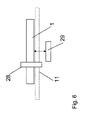
- the transport system along its transport path 11, one or more positioning units 28 to which the transport devices can be stopped precisely.
- the positioning units are provided above all in the area of treatment devices and lifting devices in order to ensure precise handling of the samples or the transport devices.
- charging stations 29 can be provided, at which the power supply (in particular power capacitors or rechargeable batteries) of the transport devices can be charged.
- the transport route establishes the logical connection between individual treatment facilities (preparation, analyzer, etc.) or automation cells (for example, laboratory automation).
- This transport route is constructed according to rules which support the individual processes and / or the treatment devices or automation cells, e.g. provide samples.
- the transport devices can also have a writable information store for the type of samples and / or the treatment facilities to be approached.
- the information about the treatment device to be approached next receives the transport device from the moving embedded controller.
- An external controller 13 manages all possible jobs and is responsible for sample logistics in the laboratory. De communication of the controller 13 with the embedded controller via a radio link (WLAN, Bluetooth). The incoming orders to the embedded controller are evaluated here via an embedded protocol handler and forwarded to the transport device or to the handling device. The Embedded Controller forwards new route information to the transport device and finally also gives the approval to proceed. The embedded controller also controls the handling device. The stored movement programs for the handling device are triggered via the external controller 13. The external control also knows the respective operating state of the treatment device and takes it into account in the interaction of handling device and treatment device as well as in determining the optimal route for the transport device.
Landscapes
- Engineering & Computer Science (AREA)
- General Engineering & Computer Science (AREA)
- Mechanical Engineering (AREA)
- Robotics (AREA)
- General Physics & Mathematics (AREA)
- Physics & Mathematics (AREA)
- Chemical & Material Sciences (AREA)
- Analytical Chemistry (AREA)
- Biochemistry (AREA)
- General Health & Medical Sciences (AREA)
- Health & Medical Sciences (AREA)
- Immunology (AREA)
- Pathology (AREA)
- Life Sciences & Earth Sciences (AREA)
- Radar, Positioning & Navigation (AREA)
- Remote Sensing (AREA)
- Automatic Analysis And Handling Materials Therefor (AREA)
- Analysing Materials By The Use Of Radiation (AREA)
- Refuse Collection And Transfer (AREA)
- Sampling And Sample Adjustment (AREA)
- Manipulator (AREA)
Description
- Die Erfindung betrifft ein Laborsystem gemäß dem Oberbegriff des Anspruchs 1.
- Ein solches Laborsystem ist z.B. aus der
EP-A-0 633 207 bekannt. - Aus dem Bereich der Zementherstellung ist ein Laborsystem bekannt, bei dem die verschiedenen Behandlungseinrichtungen um einen in der Mitte angeordneten Roboter angeordnet sind. Der Roboter übernimmt dabei den Transfer der Proben zwischen den Behandlungseinrichtungen und führt die Proben den einzelnen Behandlungseinrichtungen zu. Die Proben werden üblicherweise mittels eines Probenträgers transportiert, bei dem es sich beispielsweise um einen Becher oder einen Stahlring handelt. Das Probenmaterial befindet sich dabei wahlweise lose im Becher oder wird in den Stahlring eingepresst.
- Die Dosierung des Probenmaterials aus dem Probenträger (Becher) wird ebenfalls vom Roboter übernommen. Ein derartiger Zentralroboter ist jedoch relativ teuer und für den Menschen aufgrund seiner großen Reichweite und seiner Kinematik (große Kräfte und Beschleunigungen) potentiell gefährlich, sodass ausreichende Sicherheitsabschrankungen erforderlich sind. Außerdem sind die Aufstellungsmöglichkeiten der einzelnen Behandlungseinrichtungen durch die zentrale Anordnung des Roboters begrenzt.
- Aus der
EP-A-0 633 207 wird ein Laborsystem vorgeschlagen, bei dem der Transport der Proben zu den unterschiedlichen Behandlungseinrichtungen über ein kontinuierlich umlaufendes Transportband erfolgt. Über Stoppvorrichtungen kann das Transportband angehalten werden, um einen Probenträger an einer Behandlungseinrichtung in eine vorgegebene Halteposition zu bringen. Ein der Behandlungseinrichtung zugeordnetes Handhabungsgerät bewirkt dann den Transport eines Probenträger aus der Halteposition heraus zu der jeweiligen Behandlungseinrichtung und zurück. - Wenngleich bei diesem Laborsystem die Anordnung der einzelnen Behandlungseinrichtungen wesentlich variabler ist und auf einen teueren Zentralroboter verzichtet werden kann, ist das System immer noch relativ aufwendig.
- Aus der
DE 103 44 284 A1 ist eine Vorrichtung zur automatisierten Durchführung von Laborarbeitsschritten bekannt, wobei mindestens eine Station zum automatischen Wechseln von flüssigen Medien in Probebehältern vorgesehen ist. - Aus der Praxis ist weiterhin ein Laborsystem bekannt, bei dem die Proben mit einem selbstfahrenden Roboter transportiert werden, der z.B. mit einem Laserscanner ausgestattet ist, um Hindernissen ausweichen zu können.
- Aus der
DE 200 06 549 U 1 ist eine Vorrichtung zum automatischen Durchführen von chemischen bzw. biologischen Verfahren in Probengefäßen bekannt. Hierbei werden die Probengefäße über einen Bandförderer zu einer Behandlungseinrichtung transportiert. Dabei werden die von Bandförderer erreichbaren Endstellungen eines Förderschlittens sensorisch überwacht. Über ein im Bereich der Behandlungseinrichtung vorgesehenes Handhabungsgerät erfolgt der Transfer der Probengefäße zwischen Förderschlitten und Behandlungseinrichtung. - In der
DE 199 30 019 A1 wird eine Einrichtung zum Steuern des Transports von Reinigungsgut auf einer Transportbahn beschrieben. Die Abstände und die Ausrichtung des Reinigungsgutes auf der Transportbahn werden mit Hilfe einer Kamera und einer Bildverarbeitung überwacht. - Das Steuern einer Fördertechnik mittels rechnergestützter Bilderkennung ist außerdem aus der
DE 10 2006 015 689 A1 , derDE 10 2006 002 704 A1 und derDE 10 2005 063 193 A1 bekannt. - In der
DE 203 10 903 U1 und derDE 87 17 574 U1 werden ferner optoelektronische Elemente zur Positions- bzw. Objekterkennung bei Fördersystemen eingesetzt. - Die
DE 32 08 901 A1 offenbart ferner ein Verfahren und eine Vorrichtung zur Verhinderung von Unfällen zwischen einer verfahrbaren Arbeitsmaschine und einer oder mehreren sich in ihrem Bewegungsbereich befindlichen Personen, wobei das Unterschreiten eines Mindestabstandes mittels Sender und Empfänger festgestellt wird und durch Auslösung eines Steuersignals die Fahr- und/oder Arbeitsbewegung der Arbeitsmaschine unterbrochen wird. - Die
DE 295 20 515 U1 beschreibt ein Transportsystem bei dem der Wagen zur Erkennung der Führungsbahn eine CCD-Kamera aufweist. Schließlich befasst sich dieDE 2 01 20 700 U1 mit einem Flaschenumsetzer, der eine Überwachungseinrichtung mit Kamerasystem und Bildauswertung umfasst. - Der Erfindung liegt die Aufgabe zugrunde, ein Laborsystem zu schaffen, dass ein paralleles Arbeiten von Mensch und Maschine ermöglicht, ohne dass aufwendige Sicherheitsabschrankungen erforderlich sind.
- Erfmdungsgemäß wird diese Aufgabe durch die Merkmale des Anspruches 1 gelöst.
- Das erfindungsgemäße Laborsystem besteht im Wesentlichen aus einer oder mehreren Transporteinrichtung(en) für Proben, wenigstens zwei Behandlungseinrichtungen zur Aufbereitung, Analyse und oder Bearbeitung von Proben, wenigstens einem verfahrbaren Handhabungsgerät für das Handling der Proben im Bereich einer Behandlungseinrichtung, wobei das Handhabungsgerät für den Transfer der Probe zwischen Transporteinrichtung und Behandlungseinrichtung ausgelegt ist sowie einem mit dem Handhabungsgerät mitfahrenden Überwachungssystem zur Einhaltung eines Sicherheitsabstandes. Das Handhabungsgerät ist auf der Transporteinrichtung montiert und mit dieser zwischen wenigstens zwei Behandlungseinrichtungen verfahrbar, und bei dem Überwachungssystem handelt es sich um ein mit dem Handhabungsgerät mitfahrendes Überwachungssystem, das durch eine Kamera zur Erzeugung von Entfernungsbildern und/oder ein Ortungssystem mit wenigstens einem Sender und wenigstens einem Empfänger gebildet wird. Der Empfänger des Ortungssystems wird an der verfahrbaren Transporteinrichtung montiert und ist derart ausgebildet, dass er ein Alarmsignal erzeugt, wenn der wenigstens eine von Laborpersonal zu tragende Sender einen Mindestabstand zum Empfänger unterschreitet. Die Kamera wird an das Handhabungsgerät oder ebenfalls an der Transporteinrichtung befestigt. Das Überwachungssystem wird eingesetzt, wenn von dem auf der verfahrbaren Transporteinrichtung montierten Handhabungsgerät Gefährdungspotential für Menschen ausgeht.
- Durch das Überwachungssystem, das vorzugsweise sowohl die Kamera als auch das Ortungssystem umfasst, ist ein paralleles Arbeiten von Mensch und Maschine in relativer Nähe zueinander möglich, ohne dass aufwendige Sicherheitsabschrankungen erforderlich sind, welche die Bewegungsfreiheit einschränken.
- Weitere Ausgestaltungen der Erfindung sind Gegenstand der Unteransprüche.
- Gemäß einer weiteren Ausgestaltung der Erfindung umfasst das Überwachungssystem weiterhin eine Strom- und/oder Leistungsüberwachungseinrichtung, welche Strom- und/oder Leistungswerte des Handhabungsgerätes überwacht.
- Neben den verfahrbaren Handhabungseinrichtungen ist außerdem denkbar, dass auch wenigstens eine Behandlungseinrichtung verfahrbar ausgebildet ist, wodurch die Flexibilität des Laborsystems weiter erhöht werden kann.
- Unter dem Begriff Probe ist ein Probenträger zu verstehen, der beispielsweise einen Becher mit Probenmaterial, einen Stahlring mit eingepresstem Probenmaterial, leere Becher, leere Stahlringe und diverse Behälter unterschiedlicher Größe für Probenmaterial umfasst. Das Probenmaterial wird beispielsweise lose in Bechern oder Behältern transportiert wird. Es ist aber auch denkbar, dass das Probenmaterial nach geeigneter Aufbereitung in einen Stahlring gepresst wird.
- Das Handhabungsgerät kann auch so ausgelegt werden, dass es die Dosierung des Probenmaterials aus dem Probenträger, insbesondere dem Becher, an einer Behandlungseinrichtung vornehmen kann.
- Die Transporteinrichtungen können wahlweise frei fahrend oder auf einer vorgegebenen Transportstrecke, insbesondere einen Schienenweg, von einem Ort zum anderen gelangen.
- Die Transportstrecken können in unterschiedlichen Räumen und/oder auf verschiedenen Ebenen verlaufen und sind beliebig miteinander koppelbar. Gemäß einer besonderen Ausgestaltung ist das Handhabungsgerät zusammen mit ein oder mehreren Proben auf der Transporteinrichtung verfahrbar. Dabei kann auch vorgesehen werden, dass es zusätzlich auch eine oder mehrere Transporteinrichtungen gibt, die lediglich eine oder mehrere Proben transportieren.
- Gemäß einer bevorzugten Ausführungsform weisen die Transporteinrichtungen eine eigene Energieversorgung, insbesondere ein Niedervolt-System auf und können selbstfahrend ausgebildet sein. Zudem kann die Transporteinrichtung das zu tragende Handhabungsgerät oder die Behandlungseinrichtung mit Energie versorgen.
- Zweckmäßigerweise ist die Transportstrecke modulartig aufgebaut und kann in beliebiger Art und Weise einfach ergänzt werden. Hierfür müssen (abgesehen von den Schienen) keine weiteren elektrischen Komponenten installiert werden. Gemäß einer weiteren Ausgestaltung der Erfindung umfasst das Transportsystem wenigstens eine erste und eine in vertikaler Richtung versetzt angeordnete zweite Transportstrecke, wobei zwischen der ersten und zweiten Transportstrecke eine Hebevorrichtung für die Transporteinrichtungen vorgesehen ist. Auf diese Weise können die Behandlungseinrichtungen auf unterschiedlichen Ebenen bzw. Etagen angeordnet werden. Es können auch mehrere Strecken parallel laufen und beliebig kombiniert werden.
- Weitere Vorteile und Ausgestaltungen der Erfindung werden im Folgenden anhand der Beschreibung und der Zeichnung näher erläutert.
- In der Zeichnung zeigen
- Fig. 1
- ein schematisches Blockschaltbild des Laborsystems,
- Fig. 2a-2c
- schematische Darstellungen verschiedener Ausführungen der Transporteinrichtungen (Shuttle),
- Fig. 3
- schematische Darstellung einer Transporteinrichtung mit Handhabungsgerät und Überwachungseinrichtung mit Kamera,
- Fig. 4
- schematische Darstellung der Überwachungseinrichtung mit Kamera
- Fig. 5
- schematische Darstellung des Ortungssystems und
- Fig. 6
- schematische Darstellung einer Positioniereinheit und einer Ladestation.
- Das in
Fig. 1 dargestellte Laborsystem besteht im Wesentlichen aus einer Transporteinrichtung 1 für Proben 2, mehreren Behandlungseinrichtungen 3 bis 9 und wenigstens einem Handhabungsgerät 10 für das Handling der Proben 2 im Bereich einer Behandlungseinrichtung. - Unter dem Begriff Probe ist ein Probenträger zu verstehen, der beispielsweise einen Becher mit Probenmaterial, einen Stahlring mit eingepresstem Probenmaterial, leere Becher, leere Stahlringe, diverse Behälter unterschiedlicher Größe für Probenmaterial umfasst. Das Probenmaterial wird beispielsweise lose in Bechern oder Behältern transportiert wird. Es ist aber auch denkbar, dass das Probenmaterial nach geeigneter Aufbereitung in einen Stahlring gepresst wird.
- Die Transporteinrichtungen (beispielsweise ein Shuttle) sind entweder frei fahrend ausgebildet oder sind längs einer Transportstrecke 11, insbesondere einem Schienenweg verfahrbar.
- Das Handhabungsgerät 10 kann entweder auf der Transportstrecke 11 oder einer zweiten Transportstrecke zwischen wenigstens zwei der Behandlungseinrichtungen 3 - 9 verfahren werden. Im dargestellten Ausführungsbeispiel ist das Handhabungsgerät 10 zusammen mit ein oder mehreren Proben 2 auf der Transporteinrichtung verfahrbar.
- Das Handhabungsgerät 10 ist für den Transfer der Probe 2 zwischen der Transporteinrichtung 1 und einer der Behandlungseinrichtungen 3 bis 9 ausgelegt. Das Handhabungsgerät 10 kann beispielsweise aus einem entsprechend ausgebildeten Greifarm 15 bestehen, der die Probe bzw. den Probenträger mit dem Probenmaterial aufnehmen kann und ggf. auch eine Dosierung des Probenmaterials aus dem Probenträger im Bereich einer Behandlungseinrichtung vornehmen kann. Die Dosierung kann dabei durch langsames Auskippen des Probenmaterials erfolgen. Zur Verbesserung des Fließverhaltens des Probenmaterials könnten zusätzlich noch Mittel vorgesehen werden, die den Greifer 15f des Handhabungsgerätes 10 bzw. des Greifarms 15 mit einer hochfrequenten Vibration anregen.
- Gemäß einem bevorzugten Ausführungsbeispiel ist das Laborsystem zur Aufbereitung, Analyse und/oder Bearbeitung von Proben der Zementproduktion und/oder der Erz- und Mineralienaufbereitung ausgebildet. In diesem Fall handelt es sich bei den Behandlungseinrichtungen 3 bis 9 beispielsweise um eine Rohrpostempfangsstation 3, eine Mühle/Presse 4, 5, eine Feinheitsmesseinrichtung 6, ein Spektrometer 7, ein Diffraktometer 8 und eine Rückstellung 9.
- Anhand der
Fig. 2a-2c werden nun verschiedene Ausgestaltungen der Transporteinrichtungen (Shuttle) dargestellt. Die inFig. 2a dargestellte Transporteinrichtung 1 (12.1) ist als reines Transportshuttle für ein oder mehrere Proben 2 ausgelegt. Die inFig. 2b gezeigte Transporteinrichtung 12.2 dient neben dem Transport der Proben 2 auch dem Transport eines Handhabungsgerätes 10. Die Transporteinrichtung 12.3 gemäßFig. 2c ist schließlich als reines Handhabungs-Shuttle ausgebildet und trägt lediglich ein Handhabungsgerät 10. - Gemäß einer weiteren Ausgestaltung der Erfindung weisen die Transporteinrichtungen 1 eine eigene Energieversorgung, insbesondere ein Niedervolt-System auf. Damit können die Transporteinrichtungen beispielsweise auch selbstfahrend ausgebildet werden. Zudem kann die Transporteinrichtung ein Handhabungsgerät oder eine Behandlungseinrichtung (montiert auf der Transporteinrichtung) mit Energie versorgen.
- Die Stromversorgung der Transporteinrichtungen und des Handhabungsgeräts bzw. der Behandlungseinrichtung kann aber auch über die Transportstrecke (z.B. Schiene) erfolgen.
- Die Transportstrecke für die Transporteinrichtungen kann als Schienenweg ausgebildet sein, wobei sie dann zweckmäßigerweise modulartig aufgebaut ist, sodass sie in beliebiger Form und Ausdehnung ausgebildet werden kann.
- Um eine noch größere Flexibilität der Streckenführung zu erreichen, könnte eine erste und eine in vertikaler Richtung versetzt angeordnete zweite Transportstrecke vorgesehen werden, wobei zwischen der ersten und der zweiten Transportstrecke eine Hebevorrichtung 14 für die Transporteinrichtungen vorgesehen ist (
Fig. 1 ). Verbindungen von Strecken auf unterschiedlichen Ebenen sind somit realisierbar. - Selbstverständlich sind im Rahmen der Erfindung auch beliebig andere Ausbaustufen der Transportstrecke denkbar und können an die jeweiligen Laborbedingungen angepasst werden. Mit dem obigen Konzept ist eine freie Raumgestaltung möglich, da die Behandlungseinrichtungen nahezu beliebig im Raum aufgestellt werden können.
-
Fig.3 zeigt ein auf einer Transporteinrichtung 1 montiertes und damit verfahrbares Handhabungsgerät 10. Das Handhabungsgerät wird hier beispielhaft durch einen speziellen Greifarm 15 gebildet. Desweiteren wird hier eine an den Greifarm befestigte Kamera 21 zur Erzeugung von Entfernungsbildern gezeigt. Die Kamera 21 kann aber auch an die verfahrbare Transporteinrichtung montiert werden - Der Greifarm 15 ist hier als skalierbarer Leichtbauarm ausgebildet und weist mehrere Dreh- und Schwenkeinheiten 15a, 15b, 15c, 15d und 15e auf, durch die rekonfigurierbare, modulare Roboterstrukturen realisiert werden können. Hinzu kommt noch ein elektrischer Greifer 15f. Die einzelnen Antriebsmodule (Greifer und Dreh-/Schwenkeinheiten) können mit Verbindungsteilen frei und flexibel zu einem individuellen Leichtbauarm in der IP65-Schutzklasse montiert werden.
- Der Aktionsradius ist durch freie Wahl der kinematischen Struktur an die Applikation anpassbar. Die Dreh- und Schwenkeinheiten werden beispielsweise von bürstenlosen Servomotoren mit Harmonic-Drive-Getriebe bewegt und weisen bereits eine komplette Leistungs- und Steuerelektronik auf, die Positionierfahrten mit Rampensteuerung sowie eine Endlagen-, Spannungs-, Strom- und Temperaturüberwachung ermöglicht. Durch den Einsatz leichter und gleichzeitig hochstabiler Materialien erreichen die kompakten Schwenkeinheiten ein Eigenmasse-Traglast-Verhältnis, das besser ist als 2:1 ist. Die Spannungsversorgung, die Ansteuerungsmöglichkeiten und die universellen Kommunikations-Schnittstellen können bereits integriert sein, sodass zur Antriebsvernetzung lediglich ein Kabel erforderlich ist.
- Da die Antriebskomponenten mit Hohlwellen ausgestattet sind, kann die Verkabelung innen liegend und damit geschützt geführt werden. Die 24V Gleichspannung ist für den Betrieb des Leichtbauarms ausreichend. Der geringe Energiebedarf des Leichtbauarms wird zweckmäßigerweise vom Bordnetz der Transporteinrichtung gedeckt. Die Steuerung des Leichtbauarms erfolgt beispielsweise über einen Embedded Controller auf Basis eines Einplatinen-PC's. Eine spezielle Robotersteuerung (bekannt von Industrierobotern) ist somit nicht erforderlich.
- Die Transporteinrichtung 1 (Aufbau mit Handhabungsgerät 10) weist außerdem eine Überwachungseinrichtung 20 auf, die im Ausführungsbeispiel gemäß
Fig. 3 durch eine Kamera 21 zur Erzeugung von Entfernungsbildern gebildet wird. - Bei der Kamera 21 kann es sich beispielsweise um eine sogenannte TOF-Kamera (Time-of-Flight-Kamera) handeln. Das TOF-Prinzip basiert auf der Messung der Lichtlaufzeit. Man sendet einen Lichtimpuls aus und misst die Zeit, die das Licht benötigt, um von einem Objekt reflektiert wieder zurückzukehren. Auf diese Weise kann zu jedem Pixel der Abstand zu einem Objekt ermittelt werden, sodass man eine dreidimensionale Struktur der Szene erhält.
- Die Behandlungsstationen werden von der Transporteinrichtung angefahren, wobei die nähere Umgebung der jeweiligen Behandlungsstation von der Kamera bildlich erfasst und ein Muster generiert wird. Die Bildaufnahme erfolgt an jeder Behandlungsstation, sodass die Arbeitsumgebungen für das Handhabungsgerät aufgenommen und erlernt werden. Die jeweilige Bildaufnahme erfolgt zunächst ohne Eingriffe an den Geräten durch Bedienpersonal (so genannte statische Bildaufnahme).
- Die Kamera kann zur Aufnahme der vollständigen Umgebung auch verfahren werden. Ist die Kamera an dem Handhabungsgerät befestigt, wird sie automatisch in Arbeitsrichtung des Handhabungsgeräts ausgerichtet.
- Im Automatikbetrieb werden die Behandlungsstationen beliebig von den Transporteinrichtungen angefahren. Zudem darf das Laborpersonal im gleichen Raum mit den Behandlungsstationen arbeiten. Für den manuellen Zugriff auf die Behandlungsstationen werden die Geräte in der Regel in den Service- oder Manual-Mode geschaltet. Da nicht ausgeschlossen werden kann, dass das Personal auch in den Arbeitsraum der Handhabungseinheit greift oder sich dort befindet, wird dieser Arbeitsraum über die Kamera überwacht. Vor und während der Durchführung der Handhabungsaufgaben durch das Handhabungsgerät werden ausreichend schnell neue Bildinformationen generiert und mit dem aufgenommenen statischen Bild verglichen. Abweichungen von den ursprünglichen Bildern z.B. bei Eintritt von Personen in den Überwachungsbereich werden ausreichend schnell erkannt und führen zur Abschaltung des Handhabungsgerätes.
- Hierfür weist die Überwachungseinrichtung 20 gemäß
Fig. 4 neben der Kamera 21 eine Auswertungsschaltung 22 auf, die mit einem Abschaltschaltkreis 23 zusammenwirkt, um das Handhabungsgerät 10 abzuschalten, wenn ein vorgegebener Sicherheitsabstand unterschritten wird. - Es können somit Personen, die im Arbeitsbereicht des Handhabungsgeräts oder auf der Verfahrstrecke der Transporteinrichtung rechtzeitig detektiert werden. Durch das speziell implementierte Auswerteverfahren (Differenzbildanalyse) werden Unterschreitungen des Sicherheitsabstandes schnell erkannt und Bewegungen des Handhabungsgerätes sicherheitstechnisch unterbunden. Zudem können unterschiedliche Sicherheitszonen eingerichtet werden, so dass bei Annäherung von Personen zunächst nur die Geschwindigkeit des Handhabungsgeräts reduziert werden kann. Die Warn- und Schutzfelder sind flexible konfigurierbar.
- Um die Anforderungen einer Zusammenarbeit von Mensch und Maschine ohne Sicherheitsabtrennungen / Schutzzaun zu erfüllen kann statt oder zusätzlich zur Überwachungseinrichtung 20 mit Kamera auch ein Ortungssystem mit wenigstens einem Sender und wenigstens einem Empfänger vorgesehen werden (siehe
Fig. 5 ). Hierbei ist an der verfahrbaren Transporteinrichtung 1 ein Empfänger 25 befestigt und derart ausgebildet, dass er ein Alarmsignal erzeugt, wenn wenigstens ein Sender 26 einen Mindestabstand zum Empfänger unterschreitet. - Das Ortungssystem sieht vor, dass das Laborpersonal die Sender 26 trägt, die bei Annäherung an den am Handhabungsgerät bzw. an der Transporteinrichtung angebrachten Empfänger 25 ein Alarmsignal auslösen und über einen Abschaltschaltkreis 23 das Handhabungsgerät 10 sicherheitstechnisch stromlos schalten. Der zu überwachende Bereich ist beliebig einstellbar und kann z.B. 1 m um den Empfänger betragen. Das Tragen der Sender 26 für das Laborpersonal ist Pflicht und kann über eine weitere Empfangseinheit im Bereich des Eingangs überwacht werden (Zutrittskontrolle). Diese optionale Zutrittskontrolle überwacht das Tragen der Sender durch das Personal beim Passieren von Türen zum Labor oder Laborgebäude und löst ggf. einen Alarm aus Zudem ist eine Kopplung mit einer automatischen Türverriegelung möglich.
- Die 3D-Ortung basiert beispielsweise auf Mikrowellenentfernungsmessungen oder auf Messungen der Laufzeitunterschiede eines Funksignals 27 zu verschiedenen Empfängern. Im Vergleich zum Einsatz von Videosystemen ist bei dieser Technik kein Sichtkontakt zu den zu beobachtenden Objekten oder Personen notwendig.
- Gemäß einer weiteren Ausgestaltung kann das Überwachungssystem eine Strom-und/oder Leistungsüberwachungseinrichtung umfassen, welche Strom- und/oder Leistungswerte des Handhabungsgerätes 10 überwacht. Dabei werden insbesondere die Antriebsströme oder die Gesamtleistung des Handhabungsgeräts überwacht und ausgewertet. Die Strom/-Leistungswerte liegen redundant vor, bei Nichteinhaltung der Grenzwerte werden die Antriebe sicherheitstechnisch stromlos geschaltet. Die Energie der Handhabungseinheit kann so beispielsweise auf 80W begrenzt werden. Die Einhaltung der Grenzwerte wird auf diese Weise sicherheitstechnisch überwacht.
- Mindestens eine der drei oben beschriebenen Überwachungseinrichtungen kommt bei dem Laborsystem zum Einsatz, sodass eine indirekte Zusammenarbeit bzw. paralleles Arbeiten von Mensch und Maschine ohne die herkömmlichen Schutz-/Sicherheitsabschrankungen möglich ist. Werden mehrere verschiedene Überwachungseinrichtungen vorgesehen, kann die Sicherheit weiter erhöht werden.
- Eine indirekte Zusammenarbeit bedeutet, dass das Laborpersonal im gleichen Raum arbeiten darf, wo auch die automatische Prozesse inklusive der automatischen Handhabung ablaufen. Verschiedene Behandlungsstationen sind in den automatischen Prozess eingebunden, stehen aber auch für die manuelle Bedienung zur Verfügung. Es besteht nunmehr die Möglichkeit, zur beliebigen Zeit Bedienstationen manuell zu bedienen, während zur gleichen Zeit benachbarte Stationen in den automatischen Prozess eingebunden sind.
- Sobald sich das Laborpersonal dem Gefährdungspunkt "automatische Handhabung" annähert bzw. in den Arbeitsraum des Handhabungsgeräts gelangt bzw. greift, wird die automatische Handhabung gestoppt. Hierbei werden sämtliche sicherheitstechnischen Aspekte berücksichtigt.
- Dabei ist der Arbeitsraum des Handhabungsgerätes nicht ortsgebunden, die Überwachung des Arbeitsraumes muss daher dynamisch sein. Die Überwachung wird somit an die Transporteinrichtung gekoppelt. Ausgehend von der Transporteinrichtung wird die nähere Umgebung sicherheitstechnisch überwacht. Die nähere Umgebung ist dabei an die max. Reichweite der Handhabungseinheit gekoppelt, entsprechend wird der Überwachungsbereich eingestellt.
- Die Einrichtung der Sicherheitszonen bzw. der gesicherten Arbeitsbereiche erfordert weder aufwendige Installationen noch eine aufwendige Inbetriebnahme. Der Automatisierungsaufwand ist ebenfalls gering. Anders als bei den derzeit eingesetzten 2D-Scannern oder des Pilz Safety Eyes ist der Aufwand für die Einrichtung der Sicherheitszonen somit gering. Mit dem Ortungssystem ist auch die Überwachung von Bereichen, die optisch nicht detektiert werden können, möglich (Person kommt z.B. aus einer so genannten toten Zone, da Arbeitsbereich durch zu bedienendes Gerät zugestellt ist).
- Das Laborpersonal kann sich sicher und frei im Raum bewegen und alle Geräte sind leicht erreichbar (keine Abschrankungen, keine Barrieren). Alle marktgängigen Labor-Behandlungsstationen können an beliebiger Stelle frei im Raum aufgestellt werden und müssen nicht mit Sicherheitsabschrankungen gesichert werden.
- Darüber hinaus besteht die Möglichkeit, dass an ein oder mehreren Behandlungseinrichtungen wahlweise oder simultan eine manuelle und/oder automatische Handhabung (Transport und/oder Handling der Proben) möglich ist. Dabei sind die Transporteinrichtung und das Handling der Proben mit dem Handhabungsgerät zweckmäßigerweise auf der einen Seite und die Bedienerseite auf der anderen Seite der Behandlungseinrichtung vorgesehen.
- Die manuelle Handhabung kann beispielsweise darin bestehen, dass das Laborpersonal die Arbeit des Handhabungsgerätes, beispielsweise den Transfer von einer Transporteinrichtung in die Behandlungseinrichtung, übernimmt. Es ist aber auch denkbar, dass selbst der Transport einer Probe zur Behandlungseinrichtung vom Bediener/Mensch durchgeführt wird. Die manuelle Handhabung wird vor allem dadurch ermöglicht, dass das System keine Sicherheitsabschrankungen, wie Schutztüren, erfordert.
- In einer weiteren Ausgestaltung der Erfindung zeichnet sich das Laborsystem durch eine erweiterbare bedarforientierte Gerätelogistik aus, wobei ein oder mehrere Behandlungseinrichtungen verfahrbar ausgebildet sind und dort hintransportiert werden, wo sie gerade benötigt werden. Es gibt somit folgende Möglichkeiten:
- a) Handhabungsgerät auf einer Transporteinrichtung fährt zu einer Behandlungseinrichtung;
- b) Proben werden zu einer stationären Behandlungseinrichtung, zu einem verfahrbaren Handhabungsgerät oder zum Bediener transportiert;
- c) Behandlungseinrichtungen fahren zu einem Bediener oder zu einem stationären oder verfahrbaren Handhabungsgerät.
- Mobile Behandlungseinrichtungen können z.B. spezielle Dosiersysteme, Probenteiler o.a. Geräte sein, die auf einer Transporteinrichtung montiert sind. Die Behandlungseinrichtungen auf der Transporteinrichtung werden wie das Handhabungsgerät von dem Embedded Controller gesteuert.
- Hierdurch kann der Arbeitsfluss im Labor durch die Wegereduktion weiter optimiert werden. Ist z.B. einen verfahrbares Handhabungsgerät durch hohes Probenaufkommen an ein oder mehreren Behandlungseinrichtungen gebunden, kann die verfahrbare Behandlungseinrichtung auch in den Arbeitsbereich des verfahrbaren Handhabungsgeräts fahren und bedient werden. Zudem können verfahrbare/mobile Behandlungseinrichtungen hinzugezogen werden, um den Probenfluss an beliebiger Stelle zu verbessern oder zu beschleunigen. Des Weiteren können die mobilen Behandlungseinrichtungen auch stationäre Handhabungsgeräte anfahren.
- Die mobilen Behandlungseinheiten werden als mobile Hardware-Serviceeinheiten betrachtet. Die mobilen Hardware-Serviceeinheiten können lokal in bestimmter Umgebung agieren und eingesetzt werden, aber auch von anderen Automationszellen angefordert werden. Somit können verschiedene Automationszellen auf gleiche Ressourcen (Hardware-Service) zugreifen und diese je nach Auslastung bedarfsgerecht nutzen. Jeder Automationszelle (eine Automationszelle kann aus einer oder mehreren Behandlungseinrichtungen bestehen oder ein komplexer Automat sein) sind die nutzbaren Ressourcen bekannt und können von dieser angefordert werden. Somit kann eine Automationszelle dynamisch bei Bedarf erweitert werden. Die Kopplung von neuen oder vorhandenen Automaten mit einem frei konfigurierbaren System ist zudem möglich.
- Die mobilen Einheiten werden nicht zwingend einer Automationszelle zugeordnet. Die mobile Einheit stellt sich und damit ihren Service (Hardware-Service) zur Verfügung. Jede mobile Einheit ist autark und kann in ihrer Art vielfach vorhanden sein, dabei ist jede eigenständige Einheit mit dem Embedded Controller ausgestattet. Dieser ermöglicht die datentechnische Laborvernetzung, integriert sich automatisch in die vorhandene Umgebung (macht sich bekannt) und steuert die jeweilige mitgeführte Behandlungseinrichtung oder das Handhabungsgerät.
- Das System sieht somit neben den stationären Behandlungseinrichtungen, die von einem mobilen Handhabungsgerät angefahren und bedient werden noch variable und verfahrbare Behandlungseinrichtungen vor, die beliebig nutzbar sind und das System dynamisch erweitern können.
- In einer weiteren Ausgestaltung der Erfindung (
Fig. 6 ) weist das Transportsystem entlang seiner Transportstrecke 11 ein oder mehrere Positioniereinheiten 28 auf, an den die Transporteinrichtungen punktgenau angehalten werden können. Die Positioniereinheiten sind vor allem im Bereich der Behandlungseinrichtungen und Hebevorrichtungen vorgesehen, um ein exaktes Handling der Proben bzw. der Transporteinrichtungen zu gewährleisten. - Weiterhin können Ladestationen 29 vorgesehen werden, an denen die Energieversorgung (insbesondere Leistungskondensatoren oder Akkus) der Transporteinrichtungen aufgeladen werden können.
- Die Transportstrecke stellt die logische Verbindung zwischen einzelnen Behandlungseinrichtungen (Aufbereitung, Analysator, etc.) oder Automationszellen (z.B. Laborautomat) her. Diese Transportstrecke wird nach Regeln aufgebaut, welche die einzelnen Prozesse unterstützen und/oder die Behandlungseinrichtungen bzw. Automationszellen z.B. mit Proben versorgen.
- Die Transporteinrichtungen können zudem einen beschreibbaren Informationsspeicher für die Art der Proben und/oder die anzufahrenden Behandlungseinrichtungen aufweisen.
- Die Information über die als nächstes anzufahrende Behandlungseinrichtung erhält die Transporteinrichtung von dem mitfahrenden Embedded Controller. Eine externe Steuerung 13 verwaltet alle möglichen Aufträge und ist für die Probenlogistik im Labor verantwortlich. De Kommunikation der Steuerung 13 mit dem Embedded Controller erfolgt über eine Funkverbindung (WLAN, Bluetooth). Die beim Embedded Controller eingehenden Aufträge werden hier über einen eingebetteten Protokollhandler ausgewertet und an die Transporteinrichtung oder an das Handhabungsgerät weitergeleitet. Der Embedded Controller gibt neue Routeninformationen an die Transporteinrichtung weiter und gibt schließlich auch die Freigabe zur Weiterfahrt. Der Embedded Controller steuert auch das Handhabungsgerät. Die hinterlegten Bewegungsprogramme für das Handhabungsgerät werden über die externe Steuerung 13 ausgelöst. Die externe Steuerung kennt auch den jeweiligen Betriebszustand der Behandlungseinrichtung und berücksichtigt diesen bei der Interaktion von Handhabungsgerät und Behandlungseinrichtung sowie bei Ermittlung der optimalen Route für die Transporteinrichtung.
Claims (7)
- Laborsystem mit einer oder mehreren Transporteinrichtung(en) (1) für Proben (2), wenigstens zwei Behandlungseinrichtungen (3-9) zur Aufbereitung, Analyse und/oder Bearbeitung von Proben, wenigstens einem Handhabungsgerät (10) für das Handling der Proben im Bereich einer Behandlungseinrichtung, wobei das Handhabungsgerät (10) für den Transfer der Probe (2) zwischen Transporteinrichtung (1) und Behandlungseinrichtung (3-9) ausgelegt ist sowie einem Überwachungssystem (30) zur Einhaltung eines Sicherheitsabstandes,
dadurch gekennzeichnet, dass das Handhabungsgerät (10) auf der Transporteinrichtung montiert und mit dieser zwischen wenigstens zwei Behandlungseinrichtungen (3-9) verfahrbar ist, und dass es sich um ein mit dem Handhabungsgerät (10) mitfahrendes Überwachungssystem (30) handelt, das eine Überwachungseinrichtung (20) mit Kamera (21) zur Erzeugung von Entfernungsbildern und/oder ein Ortungssystem mit wenigstens einem von Laborpersonal zu tragenden Sender (26) und wenigstens einem Empfänger (25) umfasst, wobei der Empfänger an der verfahrbaren Transporteinrichtung montiert und derart ausgebildet ist, dass er ein Alarmsignal erzeugt, wenn der wenigstens eine Sender einen Mindestabstand zum Empfänger unterschreitet. - Laborsystem nach Anspruch 1, dadurch gekennzeichnet, dass das Überwachungssystem (30) weiterhin eine Strom- und/oder Leistungsüberwachungseinrichtung umfasst, welche Strom- und/oder Leistungswerte des Handhabungsgerätes (10) überwacht.
- Laborsystem nach Anspruch 1, dadurch gekennzeichnet, dass wenigstens eine Behandlungseinrichtung verfahrbar ausgebildet ist.
- Laborsystem nach Anspruch 1, dadurch gekennzeichnet, dass das Handhabungsgerät (10) zusammen mit einer oder mehreren Proben (2) auf der Transporteinrichtung (1) verfahrbar ist.
- Laborsystem nach Anspruch 1, dadurch gekennzeichnet, dass weiterhin eine oder mehrere Transporteinrichtungen (12.2) vorgesehen sind, die lediglich eine oder mehrere Proben (2) transportieren.
- Laborsystem nach Anspruch 4, dadurch gekennzeichnet, dass die Transporteinrichtung (1) selbstfahrend ausgebildet ist.
- Laborsystem nach Anspruch 1, dadurch gekennzeichnet, dass das Laborsystem zur Aufbereitung, Analyse und/oder Bearbeitung von Proben der Zementproduktion und/oder der Erz- und Mineralienaufbereitung ausgebildet ist, wobei wenigstens einige der folgenden Behandlungseinrichtungen (3-9) vorgesehen sind: Rohrpostempfang, Mühle, Presse, Feinheitsmesseinrichtung, Spektrometer und Diffraktometer.
Applications Claiming Priority (2)
| Application Number | Priority Date | Filing Date | Title |
|---|---|---|---|
| DE102007048684A DE102007048684B4 (de) | 2007-10-10 | 2007-10-10 | Laborsystem |
| PCT/EP2008/062639 WO2009049995A1 (de) | 2007-10-10 | 2008-09-22 | Laborsystem mit einer transporteinrichtung für proben und einem überwachungssystem zur einhaltung eines sicherheitsabstandes |
Publications (2)
| Publication Number | Publication Date |
|---|---|
| EP2114627A1 EP2114627A1 (de) | 2009-11-11 |
| EP2114627B1 true EP2114627B1 (de) | 2010-11-10 |
Family
ID=40042941
Family Applications (1)
| Application Number | Title | Priority Date | Filing Date |
|---|---|---|---|
| EP08804565A Not-in-force EP2114627B1 (de) | 2007-10-10 | 2008-09-22 | Laborsystem mit einer transporteinrichtung für proben und einem überwachungssystem zur einhaltung eines sicherheitsabstandes |
Country Status (7)
| Country | Link |
|---|---|
| US (1) | US9044866B2 (de) |
| EP (1) | EP2114627B1 (de) |
| AT (1) | ATE487566T1 (de) |
| DE (2) | DE102007048684B4 (de) |
| DK (1) | DK2114627T3 (de) |
| RU (1) | RU2476308C2 (de) |
| WO (1) | WO2009049995A1 (de) |
Families Citing this family (16)
| Publication number | Priority date | Publication date | Assignee | Title |
|---|---|---|---|---|
| DE102009051145A1 (de) | 2008-10-29 | 2010-05-06 | Sms Siemag Aktiengesellschaft | Roboterisierte hüttenmännische Anlage |
| DE102009046107A1 (de) * | 2009-10-28 | 2011-05-05 | Ifm Electronic Gmbh | System und Verfahren für eine Interaktion zwischen einer Person und einer Maschine |
| DE102009046662A1 (de) * | 2009-11-12 | 2011-05-19 | Robert Bosch Gmbh | Vorrichtung zur Entnahme von Behältern |
| DE102010004467B4 (de) * | 2010-01-13 | 2011-12-15 | Polysius Ag | Laborsystem und Verfahren zum Betreiben eines Laborsystems |
| EP2353800B1 (de) * | 2010-02-05 | 2014-06-04 | KUKA Laboratories GmbH | Verfahren und Vorrichtung zur Überwachung eines Manipulatorraumes |
| DE102010046327B4 (de) * | 2010-09-23 | 2021-10-28 | Kuka Roboter Gmbh | Überwachung eines mobilen Manipulators |
| US9046506B2 (en) | 2011-11-07 | 2015-06-02 | Beckman Coulter, Inc. | Specimen container detection |
| DE102016007519A1 (de) * | 2016-06-20 | 2017-12-21 | Kuka Roboter Gmbh | Überwachung einer Anlage mit wenigstens einem Roboter |
| DE102016007520A1 (de) * | 2016-06-20 | 2017-12-21 | Kuka Roboter Gmbh | Überwachung einer Roboteranordnung |
| EP3285073A1 (de) * | 2016-08-16 | 2018-02-21 | Sartorius Stedim Biotech GmbH | Automatisierte transporteinheit und system |
| JP6434550B2 (ja) | 2017-02-06 | 2018-12-05 | ファナック株式会社 | 可搬型ロボット |
| FR3069307B1 (fr) * | 2017-07-21 | 2019-07-26 | Sidel Participations | Installation de manutention d'articles a maintenance securisee |
| RU188811U1 (ru) * | 2018-08-07 | 2019-04-24 | Общество с ограниченной ответственностью "НПО "Группа компаний машиностроения и приборостроения" | Аппарат для обработки проб биологического материала |
| US10843340B2 (en) * | 2018-08-27 | 2020-11-24 | The Boeing Company | Protected worker zones around mobile robotic platforms that manufacture aircraft |
| DE102020113249A1 (de) | 2020-05-15 | 2021-11-18 | Bayerische Motoren Werke Aktiengesellschaft | Baukastensystem für eine Handhabungsvorrichtung sowie Handhabungsvorrichtung |
| ES2974496T3 (es) * | 2020-12-22 | 2024-06-27 | Hoffmann La Roche | Sistema de laboratorio para monitorizar puntos de referencia de dispositivos de laboratorio |
Family Cites Families (38)
| Publication number | Priority date | Publication date | Assignee | Title |
|---|---|---|---|---|
| US3696368A (en) * | 1969-04-15 | 1972-10-03 | Ray B Kauffman | Radio frequency burglar alarm system |
| FR2485733A1 (fr) * | 1980-06-27 | 1981-12-31 | Ciments Fs | Dispositif automatique de fabrication d'echantillons destines a l'analyse |
| US4636137A (en) * | 1980-10-24 | 1987-01-13 | Lemelson Jerome H | Tool and material manipulation apparatus and method |
| DE3208901A1 (de) * | 1982-03-12 | 1983-09-22 | MOZELT GmbH & Co KG, Anlagetechnik, 4100 Duisburg | Verfahren und vorrichtung zur verhinderung von unfaellen zwischen einer arbeitsmaschine und einer oder mehreren personen |
| US4496521A (en) * | 1983-07-15 | 1985-01-29 | The Whittier Institute For Diabetes And Endocrinology | Insulin-potentiating peptides |
| ATE43277T1 (de) * | 1984-04-09 | 1989-06-15 | Elektroniktechnologie Get | Elektronische warn- und ueberwachungseinrichtung fuer handhabungsvorrichtungen. |
| FR2564592B1 (fr) * | 1984-05-16 | 1986-09-12 | Francais Ciments | Dispositif automatique pour la determination de certaines caracteristiques du ciment telles que finesse des grains, teneur en gypse et en filler calcaire |
| EP0179252A3 (de) | 1984-09-14 | 1987-07-15 | Siemens Aktiengesellschaft | Verfahren und Einrichtung zum Schutz von Personen, die sich im Aktionsbereich eines beweglichen Maschinenteils einer verfahr- oder verschwenkbaren Arbeitsmaschine, insbesondere eines Industrieroboters, aufhalten |
| US4652205A (en) * | 1985-05-02 | 1987-03-24 | Robotic Vision Systems, Inc. | Robot cell safety system |
| DE3788596T2 (de) * | 1986-05-30 | 1994-04-28 | Zymark Corp | Automatisches Steuersystem. |
| DE3740224A1 (de) * | 1987-11-24 | 1989-06-08 | Ifs Ing Gmbh | Erkennungsvorrichtung fuer die lage von entlang einer foerderstrecke bewegtem foerdergut, insbesondere einer warenbahn |
| US5047752A (en) * | 1989-11-14 | 1991-09-10 | Murata Wiedemann, Inc. | Safety system for a machine tool |
| DE4027596A1 (de) * | 1990-08-31 | 1992-03-12 | Vibroflotation Ag | Verfahren und vorrichtung zum herstellen einer schmal- oder schlitzwand in erdreich |
| EP0633207A1 (de) | 1993-07-07 | 1995-01-11 | Siemens Aktiengesellschaft | Transportsystem zum Transport von Proben zu unterschiedlichen Behandlungseinrichtungen |
| DE29520515U1 (de) * | 1995-05-04 | 1996-09-05 | dpm Daum + Partner Maschinenbau GmbH, 88317 Aichstetten | Transportsystem |
| US6082797A (en) * | 1998-11-02 | 2000-07-04 | Fanuc Robotics North America, Inc. | Gripping tool assembly |
| DE19930019B4 (de) * | 1999-06-30 | 2018-08-09 | Werner Meissner | Verfahren und Einrichtung zum Steuern des Transports von Reinigungsgut auf einer Transportbahn |
| DE20006549U1 (de) * | 2000-04-08 | 2001-08-16 | MWG-BIOTECH AG, 85560 Ebersberg | Vorrichtung zum Durchführen von chemischen bzw. biologischen Verfahren |
| US6650242B2 (en) * | 2001-05-25 | 2003-11-18 | Embridge Lake Pty Ltd | Mobile plant proximity detection and warning system |
| DE10152543A1 (de) * | 2001-10-24 | 2003-05-08 | Sick Ag | Verfahren und Vorrichtung zum Steuern einer sicherheitsrelevanten Funktion einer Maschine |
| DE20120700U1 (de) * | 2001-12-20 | 2003-04-30 | AUTEFA Automation GmbH, 86316 Friedberg | Flaschenbehandlungsvorrichtung |
| JP4133631B2 (ja) * | 2002-08-19 | 2008-08-13 | 日本電子株式会社 | エレクトロスプレー質量分析装置 |
| ATE352509T1 (de) * | 2002-11-09 | 2007-02-15 | Thyssenkrupp Elevator Ag | Sicherheitseinrichtung für aufzugssystem mit mehreren aufzugskabinen in einem schacht |
| DE20310903U1 (de) * | 2003-07-16 | 2003-09-25 | Leuze electronic GmbH + Co. KG, 73277 Owen | Optoelektronische Vorrichtung |
| US7501094B2 (en) * | 2003-09-15 | 2009-03-10 | Syngenta Limited | Preparation and characterization of formulations in a high throughput mode |
| DE10344284A1 (de) | 2003-09-24 | 2005-05-04 | Keyneurotek Ag | Vorrichtung und Verfahren zur automatisierten Durchführung von Laborarbeitsschritten |
| JP4082371B2 (ja) * | 2004-03-26 | 2008-04-30 | 日本電気株式会社 | 通信代理装置 |
| FR2868418B1 (fr) * | 2004-04-05 | 2008-08-29 | Inst Francais Du Petrole | Procede de production de phenylalcanes utilisant un catalyseur zeolithique a base de silice-alumine |
| US7628954B2 (en) * | 2005-05-04 | 2009-12-08 | Abbott Laboratories, Inc. | Reagent and sample handling device for automatic testing system |
| WO2007041295A2 (en) * | 2005-09-30 | 2007-04-12 | Irobot Corporation | Companion robot for personal interaction |
| US20090301522A1 (en) * | 2005-10-18 | 2009-12-10 | Aquatron Inc. | Customized Programmable Pool Cleaner Method and Apparatus |
| US7641402B2 (en) * | 2005-12-30 | 2010-01-05 | Honeywell International Inc. | Transport system for monitoring industrial process |
| DE102005063193B4 (de) * | 2005-12-30 | 2018-05-03 | Krones Aktiengesellschaft | Vorrichtung und Verfahren zum Gruppieren von Stückgut |
| AT503196B1 (de) * | 2006-01-19 | 2008-06-15 | Trumpf Maschinen Austria Gmbh | Biegepresse mit beschickungseinrichtung und verfahren zu deren betrieb |
| DE102006002704A1 (de) * | 2006-01-19 | 2007-08-02 | Henkel Kgaa | Verfahren und Vorrichtung zur Überwachung einer Produktionslinie |
| DE102006015689B4 (de) * | 2006-03-28 | 2020-07-23 | Ssi Schäfer Automation Gmbh | System und Verfahren zum Steuern einer Fördertechnik mittels rechnergestützter Bilderkennung |
| US8115650B2 (en) * | 2006-07-11 | 2012-02-14 | PSST Mobile Equipment Ltd. - Richard Shervey | Radio frequency identification based personnel safety system |
| KR101489337B1 (ko) * | 2007-01-12 | 2015-02-03 | 오펙스 코포레이션 | 아이템 소팅 방법 및 아이템 소팅 장치 |
-
2007
- 2007-10-10 DE DE102007048684A patent/DE102007048684B4/de not_active Expired - Fee Related
-
2008
- 2008-09-22 DK DK08804565.3T patent/DK2114627T3/da active
- 2008-09-22 AT AT08804565T patent/ATE487566T1/de active
- 2008-09-22 US US12/681,849 patent/US9044866B2/en not_active Expired - Fee Related
- 2008-09-22 WO PCT/EP2008/062639 patent/WO2009049995A1/de not_active Ceased
- 2008-09-22 DE DE502008001761T patent/DE502008001761D1/de active Active
- 2008-09-22 RU RU2010118459/02A patent/RU2476308C2/ru not_active IP Right Cessation
- 2008-09-22 EP EP08804565A patent/EP2114627B1/de not_active Not-in-force
Also Published As
| Publication number | Publication date |
|---|---|
| ATE487566T1 (de) | 2010-11-15 |
| DE502008001761D1 (de) | 2010-12-23 |
| DE102007048684B4 (de) | 2010-09-09 |
| RU2010118459A (ru) | 2011-11-20 |
| RU2476308C2 (ru) | 2013-02-27 |
| US20100219968A1 (en) | 2010-09-02 |
| US9044866B2 (en) | 2015-06-02 |
| DK2114627T3 (da) | 2011-02-28 |
| EP2114627A1 (de) | 2009-11-11 |
| WO2009049995A1 (de) | 2009-04-23 |
| DE102007048684A1 (de) | 2009-04-16 |
Similar Documents
| Publication | Publication Date | Title |
|---|---|---|
| DE102007048684B4 (de) | Laborsystem | |
| EP3347301B1 (de) | Vorrichtung und verfahren zum behandeln von behältnissen und verpackungen mit fluggerät zur überwachung | |
| EP2629100B1 (de) | Fördersystem für Materialproben, insbesondere medizinische Proben | |
| DE10110776B4 (de) | Verfahren zur Zuordnung einer mobilen Bedien- und/oder Beobachtungseinrichtung zu einer Maschine sowie Bedien- und/oder Beobachtungseinrichtung hierfür | |
| EP3505466B1 (de) | Automatisiertes regallagersystem und verfahren zum sicheren betreiben desselben | |
| EP3335877B1 (de) | Anlage zur additiven herstellung dreidimensionaler objekte | |
| EP3703902A1 (de) | Fördersystem und verfahren zum gleichzeitigen transport von werkstücken und werkern | |
| EP3908505B1 (de) | Fördervorrichtung, bearbeitungsanlage, verfahren zum fördern und/oder bearbeiten von gegenständen | |
| DE102009017151A1 (de) | Anlage zur Tauchbehandlung | |
| EP3908506B1 (de) | Förderverfahren und fördervorrichtung | |
| EP3466568A1 (de) | Anlage zur additiven herstellung dreidimensionaler objekte | |
| WO2019081639A1 (de) | Synchronisierung von türbewegungen in einer aufzuganlage | |
| EP3162742B1 (de) | Sortiermechanismus mit verteilter steuerung | |
| WO2000068123A1 (de) | Transportsystem | |
| EP4724817A1 (de) | Modulares system zur reversiblen erzeugung einer anlage und entsprechende anlage | |
| AT523076A4 (de) | Seilbahnstation mit Sicherheitsschranke | |
| EP2305534B1 (de) | Anordnung und Verfahren zur Aktivierung eines sicheren Betriebszustandes für ein fahrerloses Transportmittel | |
| EP1177147B1 (de) | Transportsystem | |
| DE10205656B4 (de) | Textilmaschine mit zumindest einer Wartungseinrichtung | |
| DE102019201696B4 (de) | Steuerung einer Bearbeitungsmaschine | |
| EP1023237B1 (de) | Zahnstangenaufzug | |
| DE10206893B4 (de) | Verfahren und Vorrichtung zur Positionserfassung von fahrweggebundenen Transport- und/oder Manipulationsvorrichtungen | |
| DE2834975A1 (de) | Sicherheitseinrichtung fuer ein bewegtes maschinenteil | |
| EP3770708B1 (de) | Überwachungsvorrichtung | |
| EP3321067A1 (de) | Anlage zur additiven herstellung dreidimensionaler objekte |
Legal Events
| Date | Code | Title | Description |
|---|---|---|---|
| PUAI | Public reference made under article 153(3) epc to a published international application that has entered the european phase |
Free format text: ORIGINAL CODE: 0009012 |
|
| 17P | Request for examination filed |
Effective date: 20090921 |
|
| AK | Designated contracting states |
Kind code of ref document: A1 Designated state(s): AT BE BG CH CY CZ DE DK EE ES FI FR GB GR HR HU IE IS IT LI LT LU LV MC MT NL NO PL PT RO SE SI SK TR |
|
| 17Q | First examination report despatched |
Effective date: 20091113 |
|
| GRAP | Despatch of communication of intention to grant a patent |
Free format text: ORIGINAL CODE: EPIDOSNIGR1 |
|
| GRAS | Grant fee paid |
Free format text: ORIGINAL CODE: EPIDOSNIGR3 |
|
| DAX | Request for extension of the european patent (deleted) | ||
| GRAA | (expected) grant |
Free format text: ORIGINAL CODE: 0009210 |
|
| AK | Designated contracting states |
Kind code of ref document: B1 Designated state(s): AT BE BG CH CY CZ DE DK EE ES FI FR GB GR HR HU IE IS IT LI LT LU LV MC MT NL NO PL PT RO SE SI SK TR |
|
| REG | Reference to a national code |
Ref country code: GB Ref legal event code: FG4D Free format text: NOT ENGLISH |
|
| REG | Reference to a national code |
Ref country code: CH Ref legal event code: EP Ref country code: CH Ref legal event code: NV Representative=s name: RIEDERER HASLER & PARTNER PATENTANWAELTE AG |
|
| REG | Reference to a national code |
Ref country code: IE Ref legal event code: FG4D Free format text: LANGUAGE OF EP DOCUMENT: GERMAN |
|
| REF | Corresponds to: |
Ref document number: 502008001761 Country of ref document: DE Date of ref document: 20101223 Kind code of ref document: P |
|
| REG | Reference to a national code |
Ref country code: DK Ref legal event code: T3 |
|
| REG | Reference to a national code |
Ref country code: NL Ref legal event code: VDEP Effective date: 20101110 |
|
| LTIE | Lt: invalidation of european patent or patent extension |
Effective date: 20101110 |
|
| PG25 | Lapsed in a contracting state [announced via postgrant information from national office to epo] |
Ref country code: NO Free format text: LAPSE BECAUSE OF FAILURE TO SUBMIT A TRANSLATION OF THE DESCRIPTION OR TO PAY THE FEE WITHIN THE PRESCRIBED TIME-LIMIT Effective date: 20110210 Ref country code: LT Free format text: LAPSE BECAUSE OF FAILURE TO SUBMIT A TRANSLATION OF THE DESCRIPTION OR TO PAY THE FEE WITHIN THE PRESCRIBED TIME-LIMIT Effective date: 20101110 |
|
| PG25 | Lapsed in a contracting state [announced via postgrant information from national office to epo] |
Ref country code: NL Free format text: LAPSE BECAUSE OF FAILURE TO SUBMIT A TRANSLATION OF THE DESCRIPTION OR TO PAY THE FEE WITHIN THE PRESCRIBED TIME-LIMIT Effective date: 20101110 Ref country code: CY Free format text: LAPSE BECAUSE OF FAILURE TO SUBMIT A TRANSLATION OF THE DESCRIPTION OR TO PAY THE FEE WITHIN THE PRESCRIBED TIME-LIMIT Effective date: 20101110 Ref country code: HR Free format text: LAPSE BECAUSE OF FAILURE TO SUBMIT A TRANSLATION OF THE DESCRIPTION OR TO PAY THE FEE WITHIN THE PRESCRIBED TIME-LIMIT Effective date: 20101110 Ref country code: FI Free format text: LAPSE BECAUSE OF FAILURE TO SUBMIT A TRANSLATION OF THE DESCRIPTION OR TO PAY THE FEE WITHIN THE PRESCRIBED TIME-LIMIT Effective date: 20101110 Ref country code: SE Free format text: LAPSE BECAUSE OF FAILURE TO SUBMIT A TRANSLATION OF THE DESCRIPTION OR TO PAY THE FEE WITHIN THE PRESCRIBED TIME-LIMIT Effective date: 20101110 Ref country code: SI Free format text: LAPSE BECAUSE OF FAILURE TO SUBMIT A TRANSLATION OF THE DESCRIPTION OR TO PAY THE FEE WITHIN THE PRESCRIBED TIME-LIMIT Effective date: 20101110 Ref country code: BG Free format text: LAPSE BECAUSE OF FAILURE TO SUBMIT A TRANSLATION OF THE DESCRIPTION OR TO PAY THE FEE WITHIN THE PRESCRIBED TIME-LIMIT Effective date: 20110210 Ref country code: LV Free format text: LAPSE BECAUSE OF FAILURE TO SUBMIT A TRANSLATION OF THE DESCRIPTION OR TO PAY THE FEE WITHIN THE PRESCRIBED TIME-LIMIT Effective date: 20101110 Ref country code: PT Free format text: LAPSE BECAUSE OF FAILURE TO SUBMIT A TRANSLATION OF THE DESCRIPTION OR TO PAY THE FEE WITHIN THE PRESCRIBED TIME-LIMIT Effective date: 20110310 Ref country code: IS Free format text: LAPSE BECAUSE OF FAILURE TO SUBMIT A TRANSLATION OF THE DESCRIPTION OR TO PAY THE FEE WITHIN THE PRESCRIBED TIME-LIMIT Effective date: 20110310 |
|
| REG | Reference to a national code |
Ref country code: IE Ref legal event code: FD4D |
|
| PG25 | Lapsed in a contracting state [announced via postgrant information from national office to epo] |
Ref country code: GR Free format text: LAPSE BECAUSE OF FAILURE TO SUBMIT A TRANSLATION OF THE DESCRIPTION OR TO PAY THE FEE WITHIN THE PRESCRIBED TIME-LIMIT Effective date: 20110211 |
|
| PG25 | Lapsed in a contracting state [announced via postgrant information from national office to epo] |
Ref country code: IE Free format text: LAPSE BECAUSE OF FAILURE TO SUBMIT A TRANSLATION OF THE DESCRIPTION OR TO PAY THE FEE WITHIN THE PRESCRIBED TIME-LIMIT Effective date: 20101110 Ref country code: EE Free format text: LAPSE BECAUSE OF FAILURE TO SUBMIT A TRANSLATION OF THE DESCRIPTION OR TO PAY THE FEE WITHIN THE PRESCRIBED TIME-LIMIT Effective date: 20101110 Ref country code: ES Free format text: LAPSE BECAUSE OF FAILURE TO SUBMIT A TRANSLATION OF THE DESCRIPTION OR TO PAY THE FEE WITHIN THE PRESCRIBED TIME-LIMIT Effective date: 20110221 |
|
| PG25 | Lapsed in a contracting state [announced via postgrant information from national office to epo] |
Ref country code: RO Free format text: LAPSE BECAUSE OF FAILURE TO SUBMIT A TRANSLATION OF THE DESCRIPTION OR TO PAY THE FEE WITHIN THE PRESCRIBED TIME-LIMIT Effective date: 20101110 Ref country code: SK Free format text: LAPSE BECAUSE OF FAILURE TO SUBMIT A TRANSLATION OF THE DESCRIPTION OR TO PAY THE FEE WITHIN THE PRESCRIBED TIME-LIMIT Effective date: 20101110 Ref country code: PL Free format text: LAPSE BECAUSE OF FAILURE TO SUBMIT A TRANSLATION OF THE DESCRIPTION OR TO PAY THE FEE WITHIN THE PRESCRIBED TIME-LIMIT Effective date: 20101110 |
|
| RAP2 | Party data changed (patent owner data changed or rights of a patent transferred) |
Owner name: THYSSENKRUPP POLYSIUS AG |
|
| PLBE | No opposition filed within time limit |
Free format text: ORIGINAL CODE: 0009261 |
|
| STAA | Information on the status of an ep patent application or granted ep patent |
Free format text: STATUS: NO OPPOSITION FILED WITHIN TIME LIMIT |
|
| 26N | No opposition filed |
Effective date: 20110811 |
|
| REG | Reference to a national code |
Ref country code: DE Ref legal event code: R097 Ref document number: 502008001761 Country of ref document: DE Effective date: 20110811 |
|
| PG25 | Lapsed in a contracting state [announced via postgrant information from national office to epo] |
Ref country code: IT Free format text: LAPSE BECAUSE OF FAILURE TO SUBMIT A TRANSLATION OF THE DESCRIPTION OR TO PAY THE FEE WITHIN THE PRESCRIBED TIME-LIMIT Effective date: 20101110 |
|
| REG | Reference to a national code |
Ref country code: DE Ref legal event code: R082 Ref document number: 502008001761 Country of ref document: DE Representative=s name: RA U. PA VOLKMAR TETZNER; PA MICHAEL TETZNER; , DE |
|
| REG | Reference to a national code |
Ref country code: DE Ref legal event code: R082 Ref document number: 502008001761 Country of ref document: DE Representative=s name: RECHTSANW. UND PAT.-ANW. DR.-ING. DR.JUR. VOLK, DE Effective date: 20120118 Ref country code: DE Ref legal event code: R081 Ref document number: 502008001761 Country of ref document: DE Owner name: THYSSENKRUPP RESOURCE TECHNOLOGIES AG, DE Free format text: FORMER OWNER: POLYSIUS AG, 59269 BECKUM, DE Effective date: 20120118 Ref country code: DE Ref legal event code: R081 Ref document number: 502008001761 Country of ref document: DE Owner name: THYSSENKRUPP RESOURCE TECHNOLOGIES GMBH, DE Free format text: FORMER OWNER: POLYSIUS AG, 59269 BECKUM, DE Effective date: 20120118 Ref country code: DE Ref legal event code: R082 Ref document number: 502008001761 Country of ref document: DE Representative=s name: TETZNER & PARTNER MBB PATENT- UND RECHTSANWAEL, DE Effective date: 20120118 Ref country code: DE Ref legal event code: R081 Ref document number: 502008001761 Country of ref document: DE Owner name: THYSSENKRUPP INDUSTRIAL SOLUTIONS AG, DE Free format text: FORMER OWNER: POLYSIUS AG, 59269 BECKUM, DE Effective date: 20120118 |
|
| BERE | Be: lapsed |
Owner name: POLYSIUS A.G. Effective date: 20110930 |
|
| PG25 | Lapsed in a contracting state [announced via postgrant information from national office to epo] |
Ref country code: MC Free format text: LAPSE BECAUSE OF NON-PAYMENT OF DUE FEES Effective date: 20110930 |
|
| PG25 | Lapsed in a contracting state [announced via postgrant information from national office to epo] |
Ref country code: BE Free format text: LAPSE BECAUSE OF NON-PAYMENT OF DUE FEES Effective date: 20110930 |
|
| REG | Reference to a national code |
Ref country code: AT Ref legal event code: PC Ref document number: 487566 Country of ref document: AT Kind code of ref document: T Owner name: THYSSENKRUPP POLYSIUS AG, DE Effective date: 20120823 |
|
| PG25 | Lapsed in a contracting state [announced via postgrant information from national office to epo] |
Ref country code: MT Free format text: LAPSE BECAUSE OF FAILURE TO SUBMIT A TRANSLATION OF THE DESCRIPTION OR TO PAY THE FEE WITHIN THE PRESCRIBED TIME-LIMIT Effective date: 20101110 |
|
| GBPC | Gb: european patent ceased through non-payment of renewal fee |
Effective date: 20120922 |
|
| PG25 | Lapsed in a contracting state [announced via postgrant information from national office to epo] |
Ref country code: LU Free format text: LAPSE BECAUSE OF NON-PAYMENT OF DUE FEES Effective date: 20110922 |
|
| REG | Reference to a national code |
Ref country code: DE Ref legal event code: R082 Ref document number: 502008001761 Country of ref document: DE Representative=s name: RECHTSANW. UND PAT.-ANW. DR.-ING. DR.JUR. VOLK, DE |
|
| PG25 | Lapsed in a contracting state [announced via postgrant information from national office to epo] |
Ref country code: GB Free format text: LAPSE BECAUSE OF NON-PAYMENT OF DUE FEES Effective date: 20120922 |
|
| REG | Reference to a national code |
Ref country code: DE Ref legal event code: R081 Ref document number: 502008001761 Country of ref document: DE Owner name: THYSSENKRUPP RESOURCE TECHNOLOGIES GMBH, DE Free format text: FORMER OWNER: THYSSENKRUPP POLYSIUS AG, 59269 BECKUM, DE Effective date: 20130626 Ref country code: DE Ref legal event code: R082 Ref document number: 502008001761 Country of ref document: DE Representative=s name: RECHTSANW. UND PAT.-ANW. DR.-ING. DR.JUR. VOLK, DE Effective date: 20130808 Ref country code: DE Ref legal event code: R082 Ref document number: 502008001761 Country of ref document: DE Representative=s name: RECHTSANW. UND PAT.-ANW. DR.-ING. DR.JUR. VOLK, DE Effective date: 20130626 Ref country code: DE Ref legal event code: R081 Ref document number: 502008001761 Country of ref document: DE Owner name: THYSSENKRUPP RESOURCE TECHNOLOGIES GMBH, DE Free format text: FORMER OWNER: THYSSENKRUPP RESOURCE TECHNOLOGIES AG, 59269 BECKUM, DE Effective date: 20130808 Ref country code: DE Ref legal event code: R082 Ref document number: 502008001761 Country of ref document: DE Representative=s name: TETZNER & PARTNER MBB PATENT- UND RECHTSANWAEL, DE Effective date: 20130808 Ref country code: DE Ref legal event code: R082 Ref document number: 502008001761 Country of ref document: DE Representative=s name: TETZNER & PARTNER MBB PATENT- UND RECHTSANWAEL, DE Effective date: 20130626 Ref country code: DE Ref legal event code: R081 Ref document number: 502008001761 Country of ref document: DE Owner name: THYSSENKRUPP INDUSTRIAL SOLUTIONS AG, DE Free format text: FORMER OWNER: THYSSENKRUPP POLYSIUS AG, 59269 BECKUM, DE Effective date: 20130626 Ref country code: DE Ref legal event code: R081 Ref document number: 502008001761 Country of ref document: DE Owner name: THYSSENKRUPP INDUSTRIAL SOLUTIONS AG, DE Free format text: FORMER OWNER: THYSSENKRUPP RESOURCE TECHNOLOGIES AG, 59269 BECKUM, DE Effective date: 20130808 |
|
| PG25 | Lapsed in a contracting state [announced via postgrant information from national office to epo] |
Ref country code: TR Free format text: LAPSE BECAUSE OF FAILURE TO SUBMIT A TRANSLATION OF THE DESCRIPTION OR TO PAY THE FEE WITHIN THE PRESCRIBED TIME-LIMIT Effective date: 20101110 |
|
| PG25 | Lapsed in a contracting state [announced via postgrant information from national office to epo] |
Ref country code: HU Free format text: LAPSE BECAUSE OF FAILURE TO SUBMIT A TRANSLATION OF THE DESCRIPTION OR TO PAY THE FEE WITHIN THE PRESCRIBED TIME-LIMIT Effective date: 20101110 |
|
| REG | Reference to a national code |
Ref country code: DE Ref legal event code: R082 Ref document number: 502008001761 Country of ref document: DE Representative=s name: TETZNER & PARTNER MBB PATENT- UND RECHTSANWAEL, DE |
|
| REG | Reference to a national code |
Ref country code: DE Ref legal event code: R082 Ref document number: 502008001761 Country of ref document: DE Representative=s name: TETZNER & PARTNER MBB PATENT- UND RECHTSANWAEL, DE |
|
| REG | Reference to a national code |
Ref country code: DE Ref legal event code: R081 Ref document number: 502008001761 Country of ref document: DE Owner name: THYSSENKRUPP INDUSTRIAL SOLUTIONS AG, DE Free format text: FORMER OWNER: THYSSENKRUPP RESOURCE TECHNOLOGIES GMBH, 59269 BECKUM, DE Effective date: 20140729 Ref country code: DE Ref legal event code: R082 Ref document number: 502008001761 Country of ref document: DE Representative=s name: TETZNER & PARTNER MBB PATENT- UND RECHTSANWAEL, DE Effective date: 20140729 Ref country code: DE Ref legal event code: R082 Ref document number: 502008001761 Country of ref document: DE Representative=s name: TETZNER & PARTNER MBB PATENT- UND RECHTSANWAEL, DE Effective date: 20140519 |
|
| REG | Reference to a national code |
Ref country code: FR Ref legal event code: PLFP Year of fee payment: 9 |
|
| REG | Reference to a national code |
Ref country code: FR Ref legal event code: PLFP Year of fee payment: 10 |
|
| REG | Reference to a national code |
Ref country code: FR Ref legal event code: PLFP Year of fee payment: 11 |
|
| REG | Reference to a national code |
Ref country code: DE Ref legal event code: R082 Ref document number: 502008001761 Country of ref document: DE Representative=s name: TETZNER & PARTNER MBB PATENT- UND RECHTSANWAEL, DE Ref country code: DE Ref legal event code: R081 Ref document number: 502008001761 Country of ref document: DE Owner name: THYSSENKRUPP INDUSTRIAL SOLUTIONS AG, DE Free format text: FORMER OWNER: THYSSENKRUPP INDUSTRIAL SOLUTIONS AG, 45143 ESSEN, DE |
|
| PGFP | Annual fee paid to national office [announced via postgrant information from national office to epo] |
Ref country code: DE Payment date: 20190918 Year of fee payment: 12 Ref country code: DK Payment date: 20190920 Year of fee payment: 12 Ref country code: CZ Payment date: 20190920 Year of fee payment: 12 Ref country code: FR Payment date: 20190927 Year of fee payment: 12 |
|
| PGFP | Annual fee paid to national office [announced via postgrant information from national office to epo] |
Ref country code: AT Payment date: 20190919 Year of fee payment: 12 |
|
| PGFP | Annual fee paid to national office [announced via postgrant information from national office to epo] |
Ref country code: CH Payment date: 20190919 Year of fee payment: 12 |
|
| REG | Reference to a national code |
Ref country code: DE Ref legal event code: R119 Ref document number: 502008001761 Country of ref document: DE |
|
| REG | Reference to a national code |
Ref country code: DK Ref legal event code: EBP Effective date: 20200930 |
|
| PG25 | Lapsed in a contracting state [announced via postgrant information from national office to epo] |
Ref country code: CZ Free format text: LAPSE BECAUSE OF NON-PAYMENT OF DUE FEES Effective date: 20200922 |
|
| REG | Reference to a national code |
Ref country code: CH Ref legal event code: PL |
|
| REG | Reference to a national code |
Ref country code: AT Ref legal event code: MM01 Ref document number: 487566 Country of ref document: AT Kind code of ref document: T Effective date: 20200922 |
|
| PG25 | Lapsed in a contracting state [announced via postgrant information from national office to epo] |
Ref country code: DE Free format text: LAPSE BECAUSE OF NON-PAYMENT OF DUE FEES Effective date: 20210401 Ref country code: FR Free format text: LAPSE BECAUSE OF NON-PAYMENT OF DUE FEES Effective date: 20200930 |
|
| PG25 | Lapsed in a contracting state [announced via postgrant information from national office to epo] |
Ref country code: LI Free format text: LAPSE BECAUSE OF NON-PAYMENT OF DUE FEES Effective date: 20200930 Ref country code: AT Free format text: LAPSE BECAUSE OF NON-PAYMENT OF DUE FEES Effective date: 20200922 Ref country code: CH Free format text: LAPSE BECAUSE OF NON-PAYMENT OF DUE FEES Effective date: 20200930 |
|
| PG25 | Lapsed in a contracting state [announced via postgrant information from national office to epo] |
Ref country code: DK Free format text: LAPSE BECAUSE OF NON-PAYMENT OF DUE FEES Effective date: 20200930 |