EP2113413B1 - Fahrzeugchassis für insbesondere Container, Aufbauten und dergleichen Ladungsbehälter - Google Patents
Fahrzeugchassis für insbesondere Container, Aufbauten und dergleichen Ladungsbehälter Download PDFInfo
- Publication number
- EP2113413B1 EP2113413B1 EP09000990.3A EP09000990A EP2113413B1 EP 2113413 B1 EP2113413 B1 EP 2113413B1 EP 09000990 A EP09000990 A EP 09000990A EP 2113413 B1 EP2113413 B1 EP 2113413B1
- Authority
- EP
- European Patent Office
- Prior art keywords
- vehicle chassis
- loading frame
- undercarriage
- tandem
- bar
- Prior art date
- Legal status (The legal status is an assumption and is not a legal conclusion. Google has not performed a legal analysis and makes no representation as to the accuracy of the status listed.)
- Not-in-force
Links
Images
Classifications
-
- B—PERFORMING OPERATIONS; TRANSPORTING
- B60—VEHICLES IN GENERAL
- B60P—VEHICLES ADAPTED FOR LOAD TRANSPORTATION OR TO TRANSPORT, TO CARRY, OR TO COMPRISE SPECIAL LOADS OR OBJECTS
- B60P1/00—Vehicles predominantly for transporting loads and modified to facilitate loading, consolidating the load, or unloading
- B60P1/64—Vehicles predominantly for transporting loads and modified to facilitate loading, consolidating the load, or unloading the load supporting or containing element being readily removable
- B60P1/6418—Vehicles predominantly for transporting loads and modified to facilitate loading, consolidating the load, or unloading the load supporting or containing element being readily removable the load-transporting element being a container or similar
- B60P1/6481—Specially adapted for carrying different numbers of container or containers of different sizes
-
- B—PERFORMING OPERATIONS; TRANSPORTING
- B62—LAND VEHICLES FOR TRAVELLING OTHERWISE THAN ON RAILS
- B62D—MOTOR VEHICLES; TRAILERS
- B62D21/00—Understructures, i.e. chassis frame on which a vehicle body may be mounted
- B62D21/14—Understructures, i.e. chassis frame on which a vehicle body may be mounted of adjustable length or width
-
- B—PERFORMING OPERATIONS; TRANSPORTING
- B62—LAND VEHICLES FOR TRAVELLING OTHERWISE THAN ON RAILS
- B62D—MOTOR VEHICLES; TRAILERS
- B62D21/00—Understructures, i.e. chassis frame on which a vehicle body may be mounted
- B62D21/18—Understructures, i.e. chassis frame on which a vehicle body may be mounted characterised by the vehicle type and not provided for in groups B62D21/02 - B62D21/17
- B62D21/20—Understructures, i.e. chassis frame on which a vehicle body may be mounted characterised by the vehicle type and not provided for in groups B62D21/02 - B62D21/17 trailer type, i.e. a frame specifically constructed for use in a non-powered vehicle
Definitions
- the invention relates to a vehicle chassis for in particular containers, structures or the like cargo container in one embodiment according to the preamble of claim 1.
- Vehicle chassis of the aforementioned type for transporting containers of different sizes are known.
- Containers that are to be transported on such vehicle chassis for example, 20 foot containers in the usual standardized design, but also 45 foot containers as so-called iso-containers or so-called Geest container.
- a vehicle chassis is known in which the front loading frame spar is to be adjusted and has special securing means for locking containers.
- Vehicle chassis with such a front movable load frame spar usually also have a rearward rear bumper beam which is also to be moved relative to the bogie for additional rearward deployment.
- Chassis and loading frame are also a change in length of the vehicle chassis of the tractor against each other move or pull apart. Overall, so that the desired different vehicle chassis lengths and a different wheelbase can be adjusted.
- an adjusting device are also provided over which the front loader frame spar and the rear chassis frame are to be moved. For this purpose, it is necessary that an exact length is controlled by the operator. If the vehicle chassis length is to be adjusted by a traversing motion of a towing vehicle, the towing vehicle must be positioned accordingly by the driver. This is time consuming and requires Nachpositionier matters.
- the towing vehicle can be moved forward to change the Fahrzugchassisin, after which the loading upper frame relative to the chassis frame can be locked in a different operating position. Thereafter, the valve assembly of the chassis frame with superstructure upper frame and container to lower to a lower driving position. The effort required for this is considerable and in turn requires a precise approach of a position for greater lengths of the vehicle chassis by the operator to ensure the lock in the second operating position can.
- From the generic DE 101 45 432 A1 is a transport trailer for the transport of containers known with a chassis and attached to the chassis main carrier, are attached to the front carrier and rear carrier.
- the front carrier and the rear carrier are coupled via transmission means such that when moving the front carrier relative to the main carrier of the rear carrier is coupled in an opposite direction and vice versa.
- this makes it impossible to take up positions of the front carrier or the rear carrier which occupy different distances from the main carrier.
- the vehicle chassis of the aforementioned type is characterized by the features specified in claim 1.
- a vehicle chassis in which the respective positions of the front loading frame spar and / or the rear chassis spar can be approached automatically by the lifting cylinder.
- the operator selects on a display on the control device from the required loading case (eg 45 foot container) and can confirm this by pressing a button.
- the positions of the extensions front and rear (front loading frame spar, rear chassis spar) are then controlled by the control device and automatically controlled by the system, initially the unlocking of the corresponding spars also takes place automatically. A subsequent locking after reaching the desired position can be done automatically.
- appropriate valve controls, sensors and the like are provided which receive signals from the control device and / or activate the lifting cylinders.
- the control device has a corresponding computer which performs the corresponding desired-actual-state comparison and ensures the generation of the signals.
- the vehicle chassis according to the invention is much more user-friendly than conventional chassis, as with this considerable time savings Accompanied when the driver has to go from a loading case to another load case, since he does not have to determine the appropriate positions of the parts to each other and start.
- the risk of incorrect operation is substantially reduced, which has the advantage that when fitting a container no wrong set vehicle is provided.
- the corresponding locking of chassis rail and loading frame spar can also be checked by appropriate sensors. It can also be provided that acoustic or visual warning signals are generated when a proper locking is not present or when a collision is activated to allow a start only in the correctly locked state.
- tandem lifting cylinder arrangements are provided for adjusting the loading frame Holmes and the rear chassis Holmes, the tandem lifting cylinder, which are coupled together via a lifting rod.
- These mutually associated Tandemhubzylinder have different stroke lengths, and those that must be approached for a desired load case by adjusting the front loading frame Holmes or the rear chassis Holmes. This makes it easy to ensure that such Tandem lift cylinders without having to move to intermediate positions, a total of four different longitudinal positions of a spar can be adjusted, after which the cylinders are again depressurized after reaching the appropriate length.
- the vehicle chassis in total is numbered 1.
- This has a loading frame 2 and a chassis 3, which is supported by wheels 4 on the ground.
- a larger vehicle chassis length is taken, since the loading frame 2 was moved out by a certain amount from the chassis 3 translationally.
- a transversely to the vehicle chassis longitudinal direction aligned Laderahmenholm 5 is provided in the front region of the loading frame 2 .
- Laderahmenholm 5 is provided in the front region of the loading frame 2 a transversely to the vehicle chassis longitudinal direction aligned Laderahmenholm 5 is provided.
- Laderahmenholm 5 is provided in the front region of the loading frame 2 a transversely to the vehicle chassis longitudinal direction aligned Laderahmenholm 5 is provided.
- Laderahmenholm 5 is provided in the front region of the loading frame 2 a transversely to the vehicle chassis longitudinal direction aligned Laderahmenholm 5 is provided in the front region of the loading frame 2 a transversely to the vehicle chassis longitudinal direction aligned
- the chassis spar 6 is shown in the illustration Fig. 1 shown in its retracted state. However, he can still be moved out of the chassis 3 to a certain extent for a further rear extension.
- To secure containers are generally provided with 7 numbered securing means 7, which are alternately in use, depending on which container size is set and therefore as the loading case.
- 7 numbered securing means 7 which are alternately in use, depending on which container size is set and therefore as the loading case.
- the vehicle chassis as shown, rich in variety to different load cases and thus to adapt container dimensions, which also results in charging cases are to be considered in the different wheelbases.
- a control device provided generally with 8 is provided.
- This control device can also be placed elsewhere or can also have instruments, for example, in the cab of a towing vehicle.
- This control device is connected to not shown in detail position sensors or sensors, locking parts and with the actuators of lifting cylinders for adjusting the loading frame Holmes 5 and the chassis Holmes 6.
- the control device 8 has a computer which, depending on the determined actual position positions of different chassis parts, and a predefined state of charge, automatically calculates which vehicle chassis parts are to be adjusted. This may be the front loader frame spar 7 but also the rear chassis spar 6, but it may also be necessary that the loading frame 2 and chassis 3 must move relative to each other, which is to be set in the embodiment shown by the towing vehicle.
- a braking device is activated beforehand.
- the sensors and also connected valve units are controlled so that an automatic locking of chassis parts to each other and also an automatic locking takes place when taking the appropriate position.
- Tandemhubzylinderan inches 9 and 10 are provided, each having two lifting cylinders 9.1 and 9.2 or 10.1 and 10.2, each with different stroke length.
- the respective lifting cylinders 9.1 and 9.2 are by a lifting rod 9.3 or 10.3 coupled together.
- the Tandemhubzylinderan Aunt 9 after Fig. 1 and 2 shows lifting cylinder 9.1 and 9.2, which are each fully extended, so that the loading frame spar 7 is in the maximum extended position.
- the lifting cylinders 10.1 and 10.2 are each fully retracted, so that the chassis frame 6 is in its retracted position.
- the lifting cylinders 9.1 and 9.2 as well as 10.1 and 10.2 are pneumatic cylinders. However, other lifting cylinders or adjusting means are equally suitable.
- spring-loaded cylinders are still indicated, which are connected to pivot levers 12 which are angled and cooperate with a locking device for the purpose of locking parts.
- lifting cylinders 9.1 and 9.2 or 10.1 and 10.2 have been actuated, they can each be switched back to zero pressure.
- a vehicle chassis 1 is thus made available in which fully automatically and very quickly and accurately for different container sizes and load cases, the vehicle chassis is set.
Landscapes
- Engineering & Computer Science (AREA)
- Transportation (AREA)
- Mechanical Engineering (AREA)
- Chemical & Material Sciences (AREA)
- Combustion & Propulsion (AREA)
- Body Structure For Vehicles (AREA)
- Vehicle Body Suspensions (AREA)
Description
- Die Erfindung bezieht sich auf ein Fahrzeugchassis für insbesondere Container, Aufbauten oder dergleichen Ladungsbehälter in einer Ausgestaltung gemäß dem Oberbegriff des Patentanspruches 1.
- Fahrzeugchassis der vorgenannten Art zum Transport von Containern unterschiedlicher Größe sind bekannt. Container, die auf solchen Fahrzeugchassis zu transportieren sind, sind beispielsweise 20 Fuß-Container in üblicher genormter Gestaltung, aber auch 45 Fuß-Container als sogenannte Iso-Container oder sogenannte Geest-Container.
- Aus der
DE 10 2005 050 928 A1 ist ein Fahrzeugchassis bekannt, bei dem der vordere Laderahmenholm zu verstellen ist und über besondere Sicherungsmittel zur Verriegelung von Containern verfügt. Fahrzeugchassis mit einem solchen vorderen bewegbaren Laderahmenholm haben üblicherweise auch einen rückwärtigen Heckfahrgestellholm, der für einen zusätzlichen Heckausschub ebenfalls relativ zu dem Fahrgestell zu bewegen ist. Fahrgestell und Laderahmen sind zu einer Längenveränderung des Fahrzeugchassis zudem von der Zugmaschine gegeneinander zu verfahren bzw. auseinander zu ziehen. Insgesamt können damit die gewünschten unterschiedlichen Fahrzeugchassislängen und ein unterschiedlicher Radstand eingestellt werden. - Neben der Einstellung der Relativlage zwischen Laderahmen und Fahrgestell durch das Zugfahrzeug sind darüber hinaus Hubzylinder einer Stelleinrichtung vorgesehen, über die der vordere Laderahmenholm und der rückwärtige Fahrgestellholm zu bewegen sind. Dazu ist es erforderlich, daß durch die Bedienperson eine exakte Länge angesteuert wird. Ist die Fahrzeugchassislänge durch eine Verfahrbewegung eines Zugfahrzeuges einzustellen, ist das Zugfahrzeug entsprechend genau durch den Fahrer zu positionieren. Dies ist insgesamt zeitaufwändig und erfordert Nachpositionierarbeiten.
- Aus der
EP 1 486 375 A ist eine längenveränderbares Containerchassis bekannt, bei dem ein Ladeoberrahmen mit dem Fahrgestellrahmen über die pneumatische Federung des Fahrgestells höhenverstellbar zu gestalten ist. Eine tiefere Position ist auch für HC-Container geeignet. Nur in einer höheren Position, in welcher die Unterkanten der Querträger des Lade- oder Oberrahmens höher liegen als die Oberkanten der Kotflügelanordnungen ist eine Längsverschiebung des Ladeoberrahmens gegenüber demFahrgestellrahmen möglich. Zur Absenkung bzw. zur Höhenveränderbarkeit wird über eine Ventilanordnung der pneumatischen Federung des Fahrgestells der Fahrgestellrahmen und der Ladeoberrahmen mit Container auf eine Verschiebehöhe angehoben. Über die Bremsanlage kann auf Rangierbetrieb mit Blockaderäder abgestellt werden, wobei eine Arretierung zwischen Ladeoberrahmen und Fahrgestellrahmen gelöst wird. Danach kann zur Veränderung der Fahrzugchassislänge das Zugfahrzeug vorgefahren werden, wonach der Ladeoberrahmen gegenüber dem Fahrgestellrahmen in einer anderen Betriebsposition verriegelt werden kann. Danach ist die Ventilanordnung der Fahrgestellrahmen mit Ladeoberrahmen und Container in eine tiefere Fahrposition abzusenken. Der hierfür erforderliche Aufwand ist erheblich und erfordert wiederum ein exaktes Anfahren einer Position für größere Längen des Fahrzeugchassis durch die Bedienperson, um die Verriegelung in der zweiten Betriebsposition sicherstellen zu können. - Aus der gattungsgemäßen
DE 101 45 432 A1 ist ein Transportanhänger für den Transport für Container bekannt mit einem Fahrwerk sowie einem an den Fahrwerk befestigten Hauptträger, an dem Frontträger und Heckträger befestigt sind. Die Frontträger und die Heckträger sind über Übertragungsmittel derart gekoppelt, dass beim Verfahren des Frontträgers relativ zum Hauptträger der Heckträger in eine entgegengesetzte Richtung gekoppelt wird und umgekehrt. Damit lassen sich jedoch keine Lagen des Frontträgers bzw. des Heckträgers einnehmen, die unterschiedliche Abstände zum Hauptträger einnehmen.
Es ist Aufgabe der vorliegenden Erfindung, ein Fahrzeugchassis zur Verfügung zu stellen, bei dem sich mit einem verringerten Aufwand exakt unterschiedliche Fahrzeugchassislängen einstellen lassen.
Zur Lösung dieser Aufgabe zeichnet sich das Fahrzeugchassis der eingangs genannten Art durch die im Patentanspruch 1 angegebenen Merkmale aus. - Hinsichtlich wesentlicher vorteilhafter Ausgestaltungen wird auf die Ansprüche 2 bis 9 verwiesen.
- Damit ist ein Fahrzeugchassis zur Verfügung gestellt, bei dem die jeweiligen Stellungen des vorderen Laderahmenholms und/oder des hinteren Fahrgestellholms automatisch durch die Hubzylinder angefahren werden können. Die Bedienperson wählt dazu an einem Display an der Steuervorrichtung den erforderlichen Ladefall aus (z.B. 45 Fuß-Container) und kann dies durch einen Knopfdruck bestätigen. Die Positionen der Ausschübe vorne und hinten (vorderer Laderahmenholm, hinterer Fahrgestellholm) werden dann gesteuert durch die Steuervorrichtung und vom System automatisch angesteuert, wobei zunächst die Entriegelung der entsprechenden Holme ebenfalls automatisch erfolgt. Auch eine nachfolgende Verriegelung nach Erreichen der gewünschten Position kann automatisch erfolgen. Dazu sind entsprechende Ventilsteuerungen, Sensoren und dergleichen vorgesehen, die von der Steuervorrichtung entsprechende Signale erhalten bzw. und die Hubzylinder aktivieren. Die Steuervorrichtung weist einen entsprechenden Rechner auf, der den entsprechenden Soll-Ist-Zustand-Vergleich durchführt und für die Erzeugung der Signale Sorge trägt. Damit ist das Fahrzeugchassis nach der Erfindung wesentlich benutzerfreundlicher als herkömmliche Chassis, da mit diesem eine erhebliche Zeitersparnis einhergeht, wenn der Fahrer von einem Ladefall zu einem anderen Ladefall übergehen muß, da er die entsprechenden Stellungen der Teile zueinander nicht selbst ermitteln und anfahren muß. Dadurch ist die Gefahr von Fehlbedienungen wesentlich reduziert, was den Vorteil mit sich bringt, daß beim Aufsetzen eines Containers kein falsch eingestelltes Fahrzeug vorgesehen ist. Die entsprechende Verriegelung von Fahrgestellholm und Laderahmenholm kann ebenfalls durch entsprechende Sensoren geprüft werden. Dabei kann ebenfalls vorgesehen sein, daß akustische oder optische Warnsignale erzeugt werden, wenn eine ordnungsgemäße Verriegelung nicht vorliegt bzw. wenn eine Anfahrsicherung aktiviert wird, um ein Anfahren nur im korrekt verriegelten Zustand zu ermöglichen. Ist eine Positionsveränderung zwischen Fahrgestell und Laderahmen erforderlich, wird dies auch durch die Positionsgeber nach eingestelltem Ladefall detektiert und über die Steuervorrichtung angezeigt. Dann kann die Bedienperson eine entsprechende Lageveränderung durch die Zugmaschine durchführen, wobei nach Erreichen der lagegerechten Positionierung - wiederum aktiviert durch Sensoren bzw. Positionsgeber - eine automatische Verriegelung der Teile erfolgen kann.
- Bevorzugtermaßen sind zur Verstellung des Laderahmenholmes und des rückwärtigen Fahrgestellholmes Tandemhubzylinderanordnungen vorgesehen, die Tandemhubzylinder aufweisen, die über eine Hubstange miteinander gekoppelt sind. Diese einander zugeordneten Tandemhubzylinder haben unterschiedliche Hublängen, und zwar solche, die für einen angestrebten Ladefall durch Verstellung des vorderen Laderahmenholmes bzw. des hinteren Fahrgestellholmes angefahren werden müssen. So läßt sich auf einfache Weise sicherstellen, daß mit derartigen Tandemhubzylindern ohne Zwischenpositionen anfahren zu müssen, insgesamt vier verschiedene Längsstellungen eines Holms eingestellt werden können, wonach nach Erreichen der entsprechenden Länge die Zylinder wiederum drucklos zu schalten sind. Diese vier Hubstellungen werden dadurch dargestellt, indem für die voll ausgefahrene Stellung eines Holms und damit für eine erhöhte Fahrgestellchassislänge beide Hubzylinder voll ausgefahren sind, in einer anderen Stellung nur einer der Hubzylinder voll ausgefahren ist, wohingegen der andere eingefahren ist und in der letzten und damit kürzesten Stellung beide Hubzylinder der Tandemhubzylinderanordnung eingefahren sind. Gleiches gilt auch für die Tandemhubzylinderanordnung eines rückwärtigen Fahrgestellholmes. Ebenfalls ist vorzusehen, daß bei einem Start der Steuerungsvorrichtung durch die Bedienperson automatisch eine Bremse aktiviert wird und ein Warnsignal ertönt.
- Weitere vorteilhafte Ausgestaltungen der Erfindung ergeben sich aus der weiteren Beschreibung und der Zeichnung. In der Zeichnung zeigen:
- Fig. 1
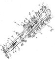
- in einer perspektivischen Darstellung ein Ausführungsbeispiel eines Fahrzeugchassis nach der Erfindung,
- Fig. 2
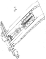
- vergrößert den vorderen Bereich des Laderahmens des Ausführungsbeispiels nach
Fig. 1 , ebenfalls in einer perspektivischen Darstellung. - In der Zeichnung sind grundsätzlich gleichwirkende Teile mit übereinstimmenden Bezugsziffern versehen. Das Fahrzeugchassis insgesamt ist mit 1 beziffert. Dieses hat einen Laderahmen 2 und ein Fahrgestell 3, das über Räder 4 auf dem Erdboden abgestützt ist. In der gezeigten Positionierung zwischen Laderahmen 2 einerseits und Fahrgestell 3 andererseits ist eine größere Fahrzeugchassislänge eingenommen, da der Laderahmen 2 um ein gewisses Maß aus dem Fahrgestell 3 translatorisch herausbewegt wurde. Im vorderen Bereich des Laderahmens 2 ist ein sich quer zur Fahrzeugchassislängsrichtung ausgerichteter Laderahmenholm 5 vorgesehen. Dieser ist an Traversen 2.1 gehaltert, die in den Hauptteil des Laderahmens 2 einführbar sind. In dem gezeigten Ausführungsbeispiel ist der vordere Laderahmenholm 5 aus dem Laderahmen 2 herausbewegt, wie dies die herausgezogenen Längstraversen 2.1 verdeutlichen. Im heckseitigen Bereich des Fahrzeugchassis 1 ist ein sich ebenfalls quer zur Fahrzeuglängsrichtung erstreckender Fahrgestellholm 6 vorgesehen. Der Fahrgestellholm 6 ist in der Darstellung nach
Fig. 1 in seinem eingefahrenen Zustand gezeigt. Für einen weiteren Heckausschub kann er jedoch noch um ein gewisses Maß aus dem Fahrgestell 3 herausbewegt werden. - Zur Sicherung von Containern sind ganz allgemein mit 7 bezifferte Sicherungsmittel 7 vorgesehen, die abwechselnd im Einsatz sind, je nachdem, welches Containermaß eingestellt ist und wie demnach der Ladefall ist. Insgesamt ist das Fahrzeugchassis, wie dargestellt, variationsreich an verschiedene Ladefälle und damit Containermaße anzupassen, wobei sich auch Ladefälle ergeben, bei der unterschiedliche Radstände zu berücksichtigen sind.
- Um mit geringem Bedienaufwand automatisch verschiedene Ladefälle einstellen zu können, ist eine allgemein mit 8 vorgesehene Steuervorrichtung vorgesehen. Diese Steuervorrichtung kann auch an anderer Stelle plaziert werden bzw. kann auch Instrumente beispielsweise auch im Fahrerhaus eines Zugfahrzeuges haben. Diese Steuerungsvorrichtung ist mit nicht im einzelnen dargestellten Positionsgebern bzw -sensoren, Verriegelungsteilen und mit den Betätigungselementen von Hubzylindern zur Verstellung des Laderahmenholmes 5 und des Fahrgestellholmes 6 verbunden. Die Steuervorrichtung 8 hat einen Rechner, der in Abhängigkeit der ermittelten Ist-Lage-Positionen verschiedener Chassisteile, und eines vorgegebenen Ladezustandes automatisch errechnet, welche Fahrzeugchassisteile zur verstellen sind. Dies kann der vordere Laderahmenholm 7 aber auch der hintere Fahrgestellholm 6 sein, es kann aber auch notwendig sein, daß sich Laderahmen 2 und Fahrgestell 3 relativ zueinander bewegen müssen, was in dem gezeigten Ausführungsbeispiel durch das Zugfahrzeug einzustellen ist. Dies wird auf einem Display angezeigt. Dabei kann auch die Richtung mit angegeben werden. Wird eine entsprechende Verstellung durchgeführt, wird vorher eine Bremsvorrichtung aktiviert. Die Sensoren und auch angeschlossene Ventileinheiten sind dabei so gesteuert, daß eine automatische Verriegelung von Chassisteilen aneinander und auch eine automatische Verriegelung bei Einnahme der entsprechenden Position erfolgt.
- Für die Steuerung des vorderen Laderahmenholmes 7 und des hinteren Fahrgestellrahmens 6 sind zwei Tandemhubzylinderanordnungen 9 und 10 vorgesehen, die jeweils zwei Hubzylinder 9.1 und 9.2 bzw. 10.1 und 10.2 aufweisen mit jeweils unterschiedlicher Hublänge. Die jeweiligen Hubzylinder 9.1 und 9.2 sind durch eine Hubstange 9.3 bzw. 10.3 miteinander gekoppelt. Die Tandemhubzylinderanordnung 9 nach
Fig. 1 und2 zeigt Hubzylinder 9.1 und 9.2, die jeweils voll ausgefahren sind, so daß der Laderahmenholm 7 sich in der maximal ausgefahrenen Stellung befindet. - Die Hubzylinder 10.1 und 10.2 sind jeweils ganz eingefahren, so daß sich der Fahrgestellrahmen 6 in seiner eingefahrenen Position handelt. Bei den Hubzylindern 9.1 und 9.2 sowie 10.1 und 10.2 handelt es sich um Pneumatikzylinder. Andere Hubzylinder bzw. Stellmittel sind jedoch gleichermaßen geeignet. Bei 11 sind noch federbelastete Zylinder angedeutet, die mit Schwenkhebeln 12 verbunden sind, die abgewinkelt ausgebildet sind und mit einer Sperreinrichtung zusammenwirken zwecks Verriegelung von Teilen.
- Sind die Hubzylinder 9.1 und 9.2 bzw. 10.1 und 10.2 betätigt worden, können sie jeweils wieder drucklos geschaltet werden.
- Insgesamt ist damit ein Fahrzeugchassis 1 zur Verfügung gestellt, bei dem vollautomatisch und dabei sehr schnell und exakt für verschiedene Containergrößen und Beladungsfälle das Fahrzeugchassis einzustellen ist.
Claims (9)
- Fahrzeugchassis (1) für insbesondere Container, Aufbauten oder dergleichen Ladungsbehälter mit einem über Räder (4) auf dem Erdboden abstützbaren Fahrgestell (3) und einem relativ translatorisch zu diesem bewegbaren und mit einer Zugmaschine koppelbaren Laderahmen (2), wobei der Laderahmen (2) einen vorderen, sich quer zur Fahrzeugchassislängsachse erstreckenden Laderahmenholm (5) und das Fahrgestell einen rückwärtigen, relativ zu dem Fahrgestell bewegbaren und sich quer zur Fahrchassislängsachse erstreckenden hinteren Fahrgestellholm (6) aufweist, und des weiteren eine Steuervorrichtung (8) vorgesehen ist, die mit Positionssensoren zur Erkennung der Lageposition des Fahrgestells (3), des Laderahmens (2), des vorderen Laderahmenholms (5) und des hinteren Fahrgestellholms (6) verbunden ist, wobei die Steuervorrichtung (8) in Abhängigkeit einer dedektierten Ladeposition einen Ist-Zustand ermittelt und in Abhängigkeit eines vorgebbaren Soll-Zustandes Steuersignale erzeugt, dadurch gekennzeichnet, dass die Verstellung des vorderen Laderahmenholms (5) und des hinteren Fahrgestellholms (6) parallel zur Fahrchassislängsachse über eine Hubmittel aufweisende Stelleinrichtung erfolgt, dass die Steuervorrichtung (8) zur Ansteuerung der als Hubzylinder (9.1, 9.2, 10.1, 10.2) ausgebildeten Hubmittel der Stelleinrichtung zur Verstellung des vorderen Laderahmenholmes (5) und des hinteren Fahrgestellholms (6) jeweils unabhängig voneinander parallel zur Fahrzeugchassislängsachse vorgesehen ist, die mit Positionssensoren zur Erkennung der Lageposition des Fahrgestells (3), des Laderahmens (2), des vorderen Laderahmenholms und des hinteren Fahrgestellholms im Hinblick auf die Lage parallel zur Fahrzeugchassislängsachse verbunden ist, wobei die Steuervorrichtung (8) in Abhängigkeit der detektierten Lagepositonen im Hinblick auf ihre Lage parallel zur Fahrzeugchassislängsachse einen Ist-Zustand ermittelt und in Abhängigkeit eines vorgegebenen Soll-Zustandes Steuersignale zur Betätigung der Hubmittel der Stelleinrichtung erzeugt, wobei des weiteren Verriegelungsmittel vorgesehen sind, die über die Steuervorrichtung (8) im Entriegelungs- und Verriegelungssinn ansteuerbar sind und wobei eine Anfahrsicherung vorgesehen ist, um ein Anfahren nur im korrekt verriegelten Zustand zu ermöglichen.
- Fahrzeugschassis nach Anspruch 1, dadurch gekennzeichnet, dass über die Steuervorrichtung (8) der Bedienperson angezeigt wird, dass eine Relativbewegung zwischen Laderahmen (2) und Fahrgestell (3) mit Hilfe der Zugmaschine zu erfolgen hat.
- Fahrzeugchassis nach Anspruch 1 oder 2, dadurch gekennzeichnet, dass bei Betätigung der Steuervorrichtung (8) für die Stelleinrichtung zur Verstellung des Laderahmenholmes (5) und des Fahrgestellholms (6) parallel zur Fahrzeugchassislängsachse eine Bremseinrichtung aktiviert wird.
- Fahrzeugschassis nach einem der Ansprüche 1 bis 3, dadurch gekennzeichnet, dass zur Lageveränderung des vorderen Laderahmenholmes (5) und/oder des hinteren Fahrgestellholmes (6) parallel zur Fahrzeugchassislängsachse über ein Hubelement (9.3, 10.3) gekoppelte Tandemhubzylinder (9.1., 9.2., 10.1, 10.2) einer Tandemhubzylinderanordnung (9,10) vorgesehen sind.
- Fahrzeugchassis nach Anspruch 4, dadurch gekennzeichnet, daß ein Tandemhubzylinder (9.1) einer Tandemzylinderanordnung (9) ortsfest an dem Laderahmen (2) bzw. an dem Fahrgestell (3) abgestützt und der andere Tandemhubzylinder (9.2) an dem Laderahmen- bzw. Fahrgestellholm (6) befestigbar ist.
- Fahrzeugchassis nach Anspruch 4 oder 5, dadurch gekennzeichnet, daß einander zugeordnete Tandemhubzylinder (9.1, 9.2, 10.1, 10.2) von der Steuervorrichtung (8) in vier Schaltstellungen schaltbar sind, wonach in der der ersten Stellung beide Tandemhubzylinder eingefahren sind, in einer zweiten Stellung beide Tandemhubzylinder ausgefahren sind, in einer dritten Stellung einer der Tandemhubzylinder ausgefahren und der andere Tandemhubzylinder eingefahren und in der vierten Stellung der andere Tandemhubzylinder (9.1, 9.2, 10.1, 10.2) ausgefahren und der eine Tandemhubzylinder eingefahren ist.
- Fahrzeugchassis nach Anspruch 6, dadurch gekennzeichnet, daß einander zugeordnete Tandemhubzylinder (9.1, 9.2, 10.1, 10.2) unterschiedliche Hublängen aufweisen.
- Fahrzeugchassis nach einem der Ansprüche 5 bis 7, dadurch gekennzeichnet daß im verriegelten Zustand der Fahrzeugchassisteile die Hubzylinder (9.1, 9.2, 10.1, 10.2) der Tandemhubzylinderanordnung(en) drucklos schaltbar sind.
- Fahrzeugchassis nach einem der Ansprüche 5 bis 8, dadurch gekennzeichnet daß Hubzylindern (9.1, 9.2) einer Tandemzylinderanordnung (9) ein federbeaufschlagtes Sperrelement (11) zugeordnet ist, das an einem abgewinkelten Betätigungsschenkel (12) angreift, das mit einem Sperrglied zwecks Feststellung und Sicherung von Laderahmenteilen zusammenwirkt.
Priority Applications (1)
| Application Number | Priority Date | Filing Date | Title |
|---|---|---|---|
| PL09000990T PL2113413T3 (pl) | 2008-04-30 | 2009-01-24 | Rama pojazdu, zwłaszcza dla kontenerów, zabudów i tego rodzaju pojemników ładunkowych |
Applications Claiming Priority (1)
| Application Number | Priority Date | Filing Date | Title |
|---|---|---|---|
| DE102008021795.6A DE102008021795B4 (de) | 2008-04-30 | 2008-04-30 | Fahrzeugchassis für insbesondere Container, Aufbauten und dergleichen Ladungsbehälter |
Publications (3)
| Publication Number | Publication Date |
|---|---|
| EP2113413A2 EP2113413A2 (de) | 2009-11-04 |
| EP2113413A3 EP2113413A3 (de) | 2009-12-02 |
| EP2113413B1 true EP2113413B1 (de) | 2018-09-05 |
Family
ID=40960319
Family Applications (1)
| Application Number | Title | Priority Date | Filing Date |
|---|---|---|---|
| EP09000990.3A Not-in-force EP2113413B1 (de) | 2008-04-30 | 2009-01-24 | Fahrzeugchassis für insbesondere Container, Aufbauten und dergleichen Ladungsbehälter |
Country Status (5)
| Country | Link |
|---|---|
| EP (1) | EP2113413B1 (de) |
| DE (1) | DE102008021795B4 (de) |
| DK (1) | DK2113413T3 (de) |
| ES (1) | ES2699480T3 (de) |
| PL (1) | PL2113413T3 (de) |
Families Citing this family (3)
| Publication number | Priority date | Publication date | Assignee | Title |
|---|---|---|---|---|
| FR3004706A1 (fr) * | 2013-04-19 | 2014-10-24 | Christophe Riquier | Ensemble pour la manutention de conteneurs facilitant la manipulation de verrous tournants |
| DE102015105225B4 (de) * | 2015-04-07 | 2023-02-16 | Eggers Fahrzeugbau GmbH | Fahrzeuganhänger sowie ein Fahrzeuggespann und ein Verfahren zur Einstellung eines Abstandes eines Zugverbindungspunktes des Fahrzeuganhängers bis zu einer Anhängerachse des Fahrzeuganhängers |
| DE102023100305B3 (de) | 2023-01-09 | 2024-02-01 | Fahrzeugwerk Bernard Krone GmbH & Co. KG | Nutzfahrzeug mit beweglichem Heckausschub |
Family Cites Families (7)
| Publication number | Priority date | Publication date | Assignee | Title |
|---|---|---|---|---|
| US5314201A (en) * | 1992-12-24 | 1994-05-24 | Rocky Mountain Technology Engineering Corp. | Locking system for a semitrailer sliding undercarriage |
| GB9715606D0 (en) * | 1997-07-24 | 1997-10-01 | Raven Kevin W | Sliding bogie trailers |
| DE10145432A1 (de) | 2001-09-14 | 2003-04-03 | Heinz-Rainer Hoffmann | Transportanhänger |
| DE10327075A1 (de) | 2003-06-13 | 2004-12-30 | Schmitz Gotha Fahrzeugwerke Gmbh | Längenverstellbares Containerchassis |
| BE1015577A3 (nl) * | 2003-06-20 | 2005-06-07 | Renders Sa | Verrijdbare constructie voor vrachtvervoer. |
| DE10332911A1 (de) * | 2003-07-19 | 2005-02-10 | Schmitz Gotha Fahrzeugwerke Gmbh | Fahrzeuganordnung mit längsverschiebbaren Teilen und Verfahren zur Längsverschiebung |
| DE102005050928B4 (de) * | 2005-10-21 | 2009-04-09 | Fahrzeugwerk Bernard Krone Gmbh | Fahrgestell für Container, Aufbauten und dergleichen Ladungsbehälter |
-
2008
- 2008-04-30 DE DE102008021795.6A patent/DE102008021795B4/de not_active Expired - Fee Related
-
2009
- 2009-01-24 DK DK09000990.3T patent/DK2113413T3/da active
- 2009-01-24 EP EP09000990.3A patent/EP2113413B1/de not_active Not-in-force
- 2009-01-24 ES ES09000990T patent/ES2699480T3/es active Active
- 2009-01-24 PL PL09000990T patent/PL2113413T3/pl unknown
Non-Patent Citations (1)
| Title |
|---|
| None * |
Also Published As
| Publication number | Publication date |
|---|---|
| PL2113413T3 (pl) | 2019-01-31 |
| EP2113413A3 (de) | 2009-12-02 |
| ES2699480T3 (es) | 2019-02-11 |
| DE102008021795B4 (de) | 2015-10-08 |
| EP2113413A2 (de) | 2009-11-04 |
| DE102008021795A1 (de) | 2009-11-12 |
| DK2113413T3 (da) | 2019-01-02 |
Similar Documents
| Publication | Publication Date | Title |
|---|---|---|
| EP1802516B1 (de) | Verschiebevorrichtung für eine sattelkupplung | |
| DE202013104703U1 (de) | Schwerlastmodulfahrzeug | |
| DE1913576A1 (de) | Container-Unterwagen | |
| DE10327075A1 (de) | Längenverstellbares Containerchassis | |
| EP2113413B1 (de) | Fahrzeugchassis für insbesondere Container, Aufbauten und dergleichen Ladungsbehälter | |
| EP1655206B1 (de) | Vorrichtung zur Unterstützung des Einparkvorgangs eines Fahrzeuges | |
| EP0490366A1 (de) | Transportfahrzeug mit Wechselaufbau | |
| DE3402442A1 (de) | Lastkraftfahrzeug | |
| EP1719661B1 (de) | Hubladebühne und Verfahren zum Ein- und Ausfahren derselben | |
| EP2388162A1 (de) | Sattelauflieger zum Transport von Containern | |
| DE4430180C2 (de) | Stütze für mit einem Zugfahrzeug gekuppelten Sattelauflieger | |
| DE102005035379B4 (de) | Mehrgliedriger Anhänger | |
| DE202016105137U1 (de) | Kraftfahrzeug mit kippbarer Ladeplattform und schwenkbarer Anhängevorrichtung | |
| DE4331613C2 (de) | Kurzkupplungssystem | |
| WO2005039960A1 (de) | Modular aufgebaute fahrerhausbaureihe | |
| DE102018001588B4 (de) | Lastkraftwagen mit hinten abgekröpftem Rahmen und ansteckbares gekröpftes Rahmenteil zur Nachrüstung eines Lastkraftwagens | |
| DE4210454C2 (de) | Sattelauflieger | |
| EP2113415B1 (de) | Fahrgestell für Container, Aufbauten und dergleichen Ladungsbehälter | |
| EP3623214B1 (de) | Nutzfahrzeug mit absenkbarem ladeboden | |
| DE2028080C3 (de) | Vorrichtung an einer Zuggabel für Anhänger, vorzugsweise für Lastkraftwagenanhänger | |
| DE102016117376B4 (de) | Kraftfahrzeug mit kippbarer Ladeplattform und schwenkbarer Anhängevorrichtung | |
| WO1998038115A1 (de) | Stützvorrichtung für container o. dgl. | |
| WO2016042147A1 (de) | Lastkraftwagen mit einer hubeinrichtung für container | |
| DE102021006473A1 (de) | Routenzuganhänger | |
| EP2512905B1 (de) | Transportfahrzeug mit integriertem anhänger |
Legal Events
| Date | Code | Title | Description |
|---|---|---|---|
| PUAI | Public reference made under article 153(3) epc to a published international application that has entered the european phase |
Free format text: ORIGINAL CODE: 0009012 |
|
| PUAL | Search report despatched |
Free format text: ORIGINAL CODE: 0009013 |
|
| AK | Designated contracting states |
Kind code of ref document: A2 Designated state(s): AT BE BG CH CY CZ DE DK EE ES FI FR GB GR HR HU IE IS IT LI LT LU LV MC MK MT NL NO PL PT RO SE SI SK TR |
|
| AX | Request for extension of the european patent |
Extension state: AL BA RS |
|
| AK | Designated contracting states |
Kind code of ref document: A3 Designated state(s): AT BE BG CH CY CZ DE DK EE ES FI FR GB GR HR HU IE IS IT LI LT LU LV MC MK MT NL NO PL PT RO SE SI SK TR |
|
| AX | Request for extension of the european patent |
Extension state: AL BA RS |
|
| 17P | Request for examination filed |
Effective date: 20100531 |
|
| 17Q | First examination report despatched |
Effective date: 20100713 |
|
| AKX | Designation fees paid |
Designated state(s): AT BE BG CH CY CZ DE DK EE ES FI FR GB GR HR HU IE IS IT LI LT LU LV MC MK MT NL NO PL PT RO SE SI SK TR |
|
| REG | Reference to a national code |
Ref country code: DE Ref legal event code: R079 Ref document number: 502009015246 Country of ref document: DE Free format text: PREVIOUS MAIN CLASS: B60P0001640000 Ipc: B62D0021140000 |
|
| RIC1 | Information provided on ipc code assigned before grant |
Ipc: B62D 21/20 20060101ALI20180306BHEP Ipc: B62D 21/14 20060101AFI20180306BHEP |
|
| GRAP | Despatch of communication of intention to grant a patent |
Free format text: ORIGINAL CODE: EPIDOSNIGR1 |
|
| STAA | Information on the status of an ep patent application or granted ep patent |
Free format text: STATUS: GRANT OF PATENT IS INTENDED |
|
| GRAS | Grant fee paid |
Free format text: ORIGINAL CODE: EPIDOSNIGR3 |
|
| INTG | Intention to grant announced |
Effective date: 20180530 |
|
| GRAA | (expected) grant |
Free format text: ORIGINAL CODE: 0009210 |
|
| STAA | Information on the status of an ep patent application or granted ep patent |
Free format text: STATUS: THE PATENT HAS BEEN GRANTED |
|
| AK | Designated contracting states |
Kind code of ref document: B1 Designated state(s): AT BE BG CH CY CZ DE DK EE ES FI FR GB GR HR HU IE IS IT LI LT LU LV MC MK MT NL NO PL PT RO SE SI SK TR |
|
| REG | Reference to a national code |
Ref country code: GB Ref legal event code: FG4D Free format text: NOT ENGLISH |
|
| REG | Reference to a national code |
Ref country code: CH Ref legal event code: EP |
|
| REG | Reference to a national code |
Ref country code: AT Ref legal event code: REF Ref document number: 1037462 Country of ref document: AT Kind code of ref document: T Effective date: 20180915 |
|
| REG | Reference to a national code |
Ref country code: IE Ref legal event code: FG4D Free format text: LANGUAGE OF EP DOCUMENT: GERMAN |
|
| REG | Reference to a national code |
Ref country code: DE Ref legal event code: R096 Ref document number: 502009015246 Country of ref document: DE |
|
| REG | Reference to a national code |
Ref country code: NL Ref legal event code: FP |
|
| REG | Reference to a national code |
Ref country code: SE Ref legal event code: TRGR |
|
| REG | Reference to a national code |
Ref country code: DK Ref legal event code: T3 Effective date: 20181218 |
|
| REG | Reference to a national code |
Ref country code: LT Ref legal event code: MG4D |
|
| PG25 | Lapsed in a contracting state [announced via postgrant information from national office to epo] |
Ref country code: BG Free format text: LAPSE BECAUSE OF FAILURE TO SUBMIT A TRANSLATION OF THE DESCRIPTION OR TO PAY THE FEE WITHIN THE PRESCRIBED TIME-LIMIT Effective date: 20181205 Ref country code: LT Free format text: LAPSE BECAUSE OF FAILURE TO SUBMIT A TRANSLATION OF THE DESCRIPTION OR TO PAY THE FEE WITHIN THE PRESCRIBED TIME-LIMIT Effective date: 20180905 Ref country code: FI Free format text: LAPSE BECAUSE OF FAILURE TO SUBMIT A TRANSLATION OF THE DESCRIPTION OR TO PAY THE FEE WITHIN THE PRESCRIBED TIME-LIMIT Effective date: 20180905 Ref country code: NO Free format text: LAPSE BECAUSE OF FAILURE TO SUBMIT A TRANSLATION OF THE DESCRIPTION OR TO PAY THE FEE WITHIN THE PRESCRIBED TIME-LIMIT Effective date: 20181205 Ref country code: GR Free format text: LAPSE BECAUSE OF FAILURE TO SUBMIT A TRANSLATION OF THE DESCRIPTION OR TO PAY THE FEE WITHIN THE PRESCRIBED TIME-LIMIT Effective date: 20181206 |
|
| PGFP | Annual fee paid to national office [announced via postgrant information from national office to epo] |
Ref country code: DK Payment date: 20181218 Year of fee payment: 11 Ref country code: PL Payment date: 20181217 Year of fee payment: 11 |
|
| REG | Reference to a national code |
Ref country code: ES Ref legal event code: FG2A Ref document number: 2699480 Country of ref document: ES Kind code of ref document: T3 Effective date: 20190211 |
|
| PG25 | Lapsed in a contracting state [announced via postgrant information from national office to epo] |
Ref country code: HR Free format text: LAPSE BECAUSE OF FAILURE TO SUBMIT A TRANSLATION OF THE DESCRIPTION OR TO PAY THE FEE WITHIN THE PRESCRIBED TIME-LIMIT Effective date: 20180905 Ref country code: LV Free format text: LAPSE BECAUSE OF FAILURE TO SUBMIT A TRANSLATION OF THE DESCRIPTION OR TO PAY THE FEE WITHIN THE PRESCRIBED TIME-LIMIT Effective date: 20180905 |
|
| PGFP | Annual fee paid to national office [announced via postgrant information from national office to epo] |
Ref country code: BE Payment date: 20181220 Year of fee payment: 11 Ref country code: GB Payment date: 20181203 Year of fee payment: 11 |
|
| PG25 | Lapsed in a contracting state [announced via postgrant information from national office to epo] |
Ref country code: IS Free format text: LAPSE BECAUSE OF FAILURE TO SUBMIT A TRANSLATION OF THE DESCRIPTION OR TO PAY THE FEE WITHIN THE PRESCRIBED TIME-LIMIT Effective date: 20190105 Ref country code: EE Free format text: LAPSE BECAUSE OF FAILURE TO SUBMIT A TRANSLATION OF THE DESCRIPTION OR TO PAY THE FEE WITHIN THE PRESCRIBED TIME-LIMIT Effective date: 20180905 Ref country code: RO Free format text: LAPSE BECAUSE OF FAILURE TO SUBMIT A TRANSLATION OF THE DESCRIPTION OR TO PAY THE FEE WITHIN THE PRESCRIBED TIME-LIMIT Effective date: 20180905 Ref country code: CZ Free format text: LAPSE BECAUSE OF FAILURE TO SUBMIT A TRANSLATION OF THE DESCRIPTION OR TO PAY THE FEE WITHIN THE PRESCRIBED TIME-LIMIT Effective date: 20180905 |
|
| PGFP | Annual fee paid to national office [announced via postgrant information from national office to epo] |
Ref country code: ES Payment date: 20190204 Year of fee payment: 11 Ref country code: IT Payment date: 20190114 Year of fee payment: 11 Ref country code: FR Payment date: 20190124 Year of fee payment: 11 Ref country code: DE Payment date: 20180919 Year of fee payment: 11 Ref country code: NL Payment date: 20190129 Year of fee payment: 11 |
|
| PG25 | Lapsed in a contracting state [announced via postgrant information from national office to epo] |
Ref country code: PT Free format text: LAPSE BECAUSE OF FAILURE TO SUBMIT A TRANSLATION OF THE DESCRIPTION OR TO PAY THE FEE WITHIN THE PRESCRIBED TIME-LIMIT Effective date: 20190105 Ref country code: SK Free format text: LAPSE BECAUSE OF FAILURE TO SUBMIT A TRANSLATION OF THE DESCRIPTION OR TO PAY THE FEE WITHIN THE PRESCRIBED TIME-LIMIT Effective date: 20180905 |
|
| PGFP | Annual fee paid to national office [announced via postgrant information from national office to epo] |
Ref country code: TR Payment date: 20190102 Year of fee payment: 11 Ref country code: SE Payment date: 20190116 Year of fee payment: 11 Ref country code: AT Payment date: 20190109 Year of fee payment: 11 |
|
| REG | Reference to a national code |
Ref country code: DE Ref legal event code: R097 Ref document number: 502009015246 Country of ref document: DE |
|
| PLBE | No opposition filed within time limit |
Free format text: ORIGINAL CODE: 0009261 |
|
| STAA | Information on the status of an ep patent application or granted ep patent |
Free format text: STATUS: NO OPPOSITION FILED WITHIN TIME LIMIT |
|
| 26N | No opposition filed |
Effective date: 20190606 |
|
| PG25 | Lapsed in a contracting state [announced via postgrant information from national office to epo] |
Ref country code: SI Free format text: LAPSE BECAUSE OF FAILURE TO SUBMIT A TRANSLATION OF THE DESCRIPTION OR TO PAY THE FEE WITHIN THE PRESCRIBED TIME-LIMIT Effective date: 20180905 Ref country code: MC Free format text: LAPSE BECAUSE OF FAILURE TO SUBMIT A TRANSLATION OF THE DESCRIPTION OR TO PAY THE FEE WITHIN THE PRESCRIBED TIME-LIMIT Effective date: 20180905 |
|
| REG | Reference to a national code |
Ref country code: CH Ref legal event code: PL |
|
| PG25 | Lapsed in a contracting state [announced via postgrant information from national office to epo] |
Ref country code: LU Free format text: LAPSE BECAUSE OF NON-PAYMENT OF DUE FEES Effective date: 20190124 |
|
| REG | Reference to a national code |
Ref country code: IE Ref legal event code: MM4A |
|
| PG25 | Lapsed in a contracting state [announced via postgrant information from national office to epo] |
Ref country code: LI Free format text: LAPSE BECAUSE OF NON-PAYMENT OF DUE FEES Effective date: 20190131 Ref country code: CH Free format text: LAPSE BECAUSE OF NON-PAYMENT OF DUE FEES Effective date: 20190131 |
|
| PG25 | Lapsed in a contracting state [announced via postgrant information from national office to epo] |
Ref country code: IE Free format text: LAPSE BECAUSE OF NON-PAYMENT OF DUE FEES Effective date: 20190124 |
|
| PG25 | Lapsed in a contracting state [announced via postgrant information from national office to epo] |
Ref country code: MT Free format text: LAPSE BECAUSE OF FAILURE TO SUBMIT A TRANSLATION OF THE DESCRIPTION OR TO PAY THE FEE WITHIN THE PRESCRIBED TIME-LIMIT Effective date: 20180905 |
|
| REG | Reference to a national code |
Ref country code: DE Ref legal event code: R119 Ref document number: 502009015246 Country of ref document: DE |
|
| REG | Reference to a national code |
Ref country code: DK Ref legal event code: EBP Effective date: 20200131 |
|
| REG | Reference to a national code |
Ref country code: SE Ref legal event code: EUG |
|
| REG | Reference to a national code |
Ref country code: NL Ref legal event code: MM Effective date: 20200201 |
|
| REG | Reference to a national code |
Ref country code: AT Ref legal event code: MM01 Ref document number: 1037462 Country of ref document: AT Kind code of ref document: T Effective date: 20200124 |
|
| GBPC | Gb: european patent ceased through non-payment of renewal fee |
Effective date: 20200124 |
|
| REG | Reference to a national code |
Ref country code: SE Ref legal event code: EUG |
|
| REG | Reference to a national code |
Ref country code: BE Ref legal event code: MM Effective date: 20200131 |
|
| PG25 | Lapsed in a contracting state [announced via postgrant information from national office to epo] |
Ref country code: NL Free format text: LAPSE BECAUSE OF NON-PAYMENT OF DUE FEES Effective date: 20200201 Ref country code: SE Free format text: LAPSE BECAUSE OF NON-PAYMENT OF DUE FEES Effective date: 20200125 Ref country code: DE Free format text: LAPSE BECAUSE OF NON-PAYMENT OF DUE FEES Effective date: 20200801 Ref country code: GB Free format text: LAPSE BECAUSE OF NON-PAYMENT OF DUE FEES Effective date: 20200124 Ref country code: FR Free format text: LAPSE BECAUSE OF NON-PAYMENT OF DUE FEES Effective date: 20200131 |
|
| PG25 | Lapsed in a contracting state [announced via postgrant information from national office to epo] |
Ref country code: BE Free format text: LAPSE BECAUSE OF NON-PAYMENT OF DUE FEES Effective date: 20200131 Ref country code: AT Free format text: LAPSE BECAUSE OF NON-PAYMENT OF DUE FEES Effective date: 20200124 |
|
| PG25 | Lapsed in a contracting state [announced via postgrant information from national office to epo] |
Ref country code: DK Free format text: LAPSE BECAUSE OF NON-PAYMENT OF DUE FEES Effective date: 20200131 Ref country code: IT Free format text: LAPSE BECAUSE OF NON-PAYMENT OF DUE FEES Effective date: 20200124 |
|
| PG25 | Lapsed in a contracting state [announced via postgrant information from national office to epo] |
Ref country code: CY Free format text: LAPSE BECAUSE OF FAILURE TO SUBMIT A TRANSLATION OF THE DESCRIPTION OR TO PAY THE FEE WITHIN THE PRESCRIBED TIME-LIMIT Effective date: 20180905 |
|
| REG | Reference to a national code |
Ref country code: ES Ref legal event code: FD2A Effective date: 20210607 |
|
| PG25 | Lapsed in a contracting state [announced via postgrant information from national office to epo] |
Ref country code: HU Free format text: LAPSE BECAUSE OF FAILURE TO SUBMIT A TRANSLATION OF THE DESCRIPTION OR TO PAY THE FEE WITHIN THE PRESCRIBED TIME-LIMIT; INVALID AB INITIO Effective date: 20090124 |
|
| PG25 | Lapsed in a contracting state [announced via postgrant information from national office to epo] |
Ref country code: ES Free format text: LAPSE BECAUSE OF NON-PAYMENT OF DUE FEES Effective date: 20200125 |
|
| PG25 | Lapsed in a contracting state [announced via postgrant information from national office to epo] |
Ref country code: PL Free format text: LAPSE BECAUSE OF NON-PAYMENT OF DUE FEES Effective date: 20200124 |
|
| PG25 | Lapsed in a contracting state [announced via postgrant information from national office to epo] |
Ref country code: TR Free format text: LAPSE BECAUSE OF NON-PAYMENT OF DUE FEES Effective date: 20200124 Ref country code: MK Free format text: LAPSE BECAUSE OF FAILURE TO SUBMIT A TRANSLATION OF THE DESCRIPTION OR TO PAY THE FEE WITHIN THE PRESCRIBED TIME-LIMIT Effective date: 20180905 |