EP2111799B1 - Biopsienadel mit einstellbarem Tiefenstopp - Google Patents
Biopsienadel mit einstellbarem Tiefenstopp Download PDFInfo
- Publication number
- EP2111799B1 EP2111799B1 EP09075358.3A EP09075358A EP2111799B1 EP 2111799 B1 EP2111799 B1 EP 2111799B1 EP 09075358 A EP09075358 A EP 09075358A EP 2111799 B1 EP2111799 B1 EP 2111799B1
- Authority
- EP
- European Patent Office
- Prior art keywords
- biopsy
- biopsy cannula
- guide
- cube
- cannula
- Prior art date
- Legal status (The legal status is an assumption and is not a legal conclusion. Google has not performed a legal analysis and makes no representation as to the accuracy of the status listed.)
- Active
Links
Images


Classifications
-
- A—HUMAN NECESSITIES
- A61—MEDICAL OR VETERINARY SCIENCE; HYGIENE
- A61B—DIAGNOSIS; SURGERY; IDENTIFICATION
- A61B17/00—Surgical instruments, devices or methods
- A61B17/34—Trocars; Puncturing needles
- A61B17/3403—Needle locating or guiding means
-
- A—HUMAN NECESSITIES
- A61—MEDICAL OR VETERINARY SCIENCE; HYGIENE
- A61B—DIAGNOSIS; SURGERY; IDENTIFICATION
- A61B10/00—Instruments for taking body samples for diagnostic purposes; Other methods or instruments for diagnosis, e.g. for vaccination diagnosis, sex determination or ovulation-period determination; Throat striking implements
- A61B10/0041—Detection of breast cancer
-
- A—HUMAN NECESSITIES
- A61—MEDICAL OR VETERINARY SCIENCE; HYGIENE
- A61B—DIAGNOSIS; SURGERY; IDENTIFICATION
- A61B10/00—Instruments for taking body samples for diagnostic purposes; Other methods or instruments for diagnosis, e.g. for vaccination diagnosis, sex determination or ovulation-period determination; Throat striking implements
- A61B10/02—Instruments for taking cell samples or for biopsy
- A61B10/0233—Pointed or sharp biopsy instruments
- A61B10/0266—Pointed or sharp biopsy instruments means for severing sample
- A61B10/0275—Pointed or sharp biopsy instruments means for severing sample with sample notch, e.g. on the side of inner stylet
-
- A—HUMAN NECESSITIES
- A61—MEDICAL OR VETERINARY SCIENCE; HYGIENE
- A61B—DIAGNOSIS; SURGERY; IDENTIFICATION
- A61B5/00—Measuring for diagnostic purposes; Identification of persons
- A61B5/70—Means for positioning the patient in relation to the detecting, measuring or recording means
- A61B5/708—Breast positioning means
-
- A—HUMAN NECESSITIES
- A61—MEDICAL OR VETERINARY SCIENCE; HYGIENE
- A61B—DIAGNOSIS; SURGERY; IDENTIFICATION
- A61B10/00—Instruments for taking body samples for diagnostic purposes; Other methods or instruments for diagnosis, e.g. for vaccination diagnosis, sex determination or ovulation-period determination; Throat striking implements
- A61B10/02—Instruments for taking cell samples or for biopsy
- A61B10/0233—Pointed or sharp biopsy instruments
- A61B10/0283—Pointed or sharp biopsy instruments with vacuum aspiration, e.g. caused by retractable plunger or by connected syringe
-
- A—HUMAN NECESSITIES
- A61—MEDICAL OR VETERINARY SCIENCE; HYGIENE
- A61B—DIAGNOSIS; SURGERY; IDENTIFICATION
- A61B17/00—Surgical instruments, devices or methods
- A61B2017/00743—Type of operation; Specification of treatment sites
- A61B2017/00796—Breast surgery
-
- A—HUMAN NECESSITIES
- A61—MEDICAL OR VETERINARY SCIENCE; HYGIENE
- A61B—DIAGNOSIS; SURGERY; IDENTIFICATION
- A61B17/00—Surgical instruments, devices or methods
- A61B17/34—Trocars; Puncturing needles
- A61B17/3403—Needle locating or guiding means
- A61B2017/3405—Needle locating or guiding means using mechanical guide means
- A61B2017/3411—Needle locating or guiding means using mechanical guide means with a plurality of holes, e.g. holes in matrix arrangement
-
- A—HUMAN NECESSITIES
- A61—MEDICAL OR VETERINARY SCIENCE; HYGIENE
- A61B—DIAGNOSIS; SURGERY; IDENTIFICATION
- A61B17/00—Surgical instruments, devices or methods
- A61B17/34—Trocars; Puncturing needles
- A61B2017/348—Means for supporting the trocar against the body or retaining the trocar inside the body
- A61B2017/3492—Means for supporting the trocar against the body or retaining the trocar inside the body against the outside of the body
-
- A—HUMAN NECESSITIES
- A61—MEDICAL OR VETERINARY SCIENCE; HYGIENE
- A61B—DIAGNOSIS; SURGERY; IDENTIFICATION
- A61B90/00—Instruments, implements or accessories specially adapted for surgery or diagnosis and not covered by any of the groups A61B1/00 - A61B50/00, e.g. for luxation treatment or for protecting wound edges
- A61B90/03—Automatic limiting or abutting means, e.g. for safety
- A61B2090/033—Abutting means, stops, e.g. abutting on tissue or skin
- A61B2090/034—Abutting means, stops, e.g. abutting on tissue or skin abutting on parts of the device itself
-
- A—HUMAN NECESSITIES
- A61—MEDICAL OR VETERINARY SCIENCE; HYGIENE
- A61B—DIAGNOSIS; SURGERY; IDENTIFICATION
- A61B90/00—Instruments, implements or accessories specially adapted for surgery or diagnosis and not covered by any of the groups A61B1/00 - A61B50/00, e.g. for luxation treatment or for protecting wound edges
- A61B90/03—Automatic limiting or abutting means, e.g. for safety
- A61B2090/033—Abutting means, stops, e.g. abutting on tissue or skin
- A61B2090/036—Abutting means, stops, e.g. abutting on tissue or skin abutting on tissue or skin
-
- A—HUMAN NECESSITIES
- A61—MEDICAL OR VETERINARY SCIENCE; HYGIENE
- A61B—DIAGNOSIS; SURGERY; IDENTIFICATION
- A61B90/00—Instruments, implements or accessories specially adapted for surgery or diagnosis and not covered by any of the groups A61B1/00 - A61B50/00, e.g. for luxation treatment or for protecting wound edges
- A61B90/06—Measuring instruments not otherwise provided for
- A61B2090/062—Measuring instruments not otherwise provided for penetration depth
Definitions
- the present invention relates in general to biopsy devices, and more particularly to biopsy devices having a cutter for severing tissue, and even more particularly to a localization and guidance fixture that guides insertion of a probe, or a sleeve that subsequently receives the probe of a biopsy device.
- a biopsy procedure may be performed using an open or percutaneous method.
- An open biopsy is performed by making a large incision in the breast and removing either the entire mass, called an excisional biopsy, or a substantial portion of it, known as an incisional biopsy.
- An open biopsy is a surgical procedure that is usually done as an outpatient procedure in a hospital or a surgical center, involving both high cost and a high level of trauma to the patient.
- Open biopsy carries a relatively higher risk of infection and bleeding than does percutaneous biopsy, and the disfigurement that sometimes results from an open biopsy may make it difficult to read future mammograms. Further, the aesthetic considerations of the patient make open biopsy even less appealing due to the risk of disfigurement. Given that a high percentage of biopsies show that the suspicious tissue mass is not cancerous, the downsides of the open biopsy procedure render this method inappropriate in many cases.
- Percutaneous biopsy is much less invasive than open biopsy.
- Percutaneous biopsy may be performed using fine needle aspiration (FNA) or core needle biopsy.
- FNA fine needle aspiration
- a very thin needle is used to withdraw fluid and cells from the suspicious tissue mass. This method has an advantage in that it is very low-pain, so low-pain that local anesthetic is not always used because the application of it may be more painful than the FNA itself.
- FNA fine needle aspiration
- a shortcoming of FNA is that only a small number of cells are obtained through the procedure, rendering it relatively less useful in analyzing the suspicious tissue and making an assessment of the progression of the cancer less simple if the sample is found to be malignant.
- a trocar penetration depth indicator that has a first, inner housing including a first threaded section and longitudinally extending gripping fingers, and a second, outer housing including a camming surface and a second threaded section to engage the first threaded section.
- the first and second housings slidably mount onto a trocar tube and can be secured relative to the guide tube by rotatably tightening the housings to cause the gripping fingers to firmly grip the trocar tube.
- MRI biopsy device localization fixture to Hughes et al., a localization mechanism, or fixture, is described that is used in conjunction with a breast coil for breast compression and for guiding a core biopsy instrument during prone biopsy procedures in both open and closed Magnetic Resonance Imaging (MRI) machines.
- the localization fixture includes a three-dimensional Cartesian positionable guide for supporting and orienting an MRI-compatible biopsy instrument, and, in particular, a sleeve to a biopsy site of suspicious tissues or lesions.
- a z-stop enhances accurate insertion, and prevents over-insertion or inadvertent retraction of the sleeve.
- the Z-stop is engaged to the localization fixture at a distance from the patient set to abut a handle of the biopsy device as an attached biopsy probe reaches the desired depth.
- another biopsy cannula may be a sleeve with a hub corresponding to a handle that contacts the z-stop.
- the present invention addresses these and other problems of the prior art by providing an apparatus for use of a depth stop device longitudinally positioned on a biopsy cannula prior to insertion into tissue.
- the depth stop device advantageously has an unlocked condition that allows positioning followed by a locking condition such that inadvertent over-insertion is affirmatively blocked.
- a device serves as the depth stop by presenting a guiding portion that substantially circumferentially encompasses a shaft of a biopsy cannula.
- a locking portion moves into binding engagement with the biopsy cannula when at a desired longitudinal position thereon.
- a transverse portion of the device precludes over insertion by coming into abutment with the skin of the patient or some proximate structure that localizes the body portion being biopsied.
- a Magnetic Resonance Imaging (MRI) compatible biopsy system 10 has a control module 12 that typically is placed outside of a shielded room containing an MRI machine (not shown) or at least spaced away to mitigate detrimental interaction with its strong magnetic field and/or sensitive radio frequency (RF) signal detection antennas.
- MRI Magnetic Resonance Imaging
- RF radio frequency
- the control module 12 controls and powers an MRI biopsy device 14 that is positioned and guided by a localization fixture 16 attached to a breast coil 18 that is placed upon a gantry (not shown) of the MRI machine.
- the control module 12 is mechanically, electrically, and pneumatically coupled to the MRI biopsy device 14 so that components may be segregated that need to be spaced away from the strong magnetic field and the sensitive RF receiving components of the MRI machine.
- a cable management spool 20 is placed upon a cable management attachment saddle 22 that projects from a side of the control module 12. Wound upon the cable management spool 20 is a paired electrical cable 24 and mechanical cable 26 for communicating control signals and cutter rotation/advancement motions respectively.
- electrical and mechanical cables 24, 26 each have one end connected to respective electrical and mechanical ports 28, 30 in the control module 12 and another end connected to a reusable holster portion 32 of the MRI biopsy device 14.
- An MRI docking cup 34 which may hold the holster portion 32 when not in use, is hooked to the control module 12 by a docking station mounting bracket 36.
- Vacuum assist is provided by a first vacuum line 46 that connects between the control module 12 and an outlet port 48 of a vacuum canister 50 that catches liquid and solid debris.
- a tubing kit 52 completes the pneumatic communication between the control module 12 and the MRI biopsy device 14.
- a second vacuum line 54 is connected to an inlet port 56 of the vacuum canister 50.
- the second vacuum line 54 divides into two vacuum lines 58, 60 that are attached to the MRI biopsy device 14.
- the control module 12 performs a functional check. Saline is manually injected into biopsy device 14 to serve as a lubricant and to assist in achieving a vacuum seal.
- the control module 12 actuates a cutter mechanism (not shown) in the MRI biopsy device 14, monitoring full travel. Binding in the mechanical cable 26 or within the biopsy device 14 is monitored with reference to motor force exerted to turn the mechanical cable 26 and/or an amount of twist in the mechanical cable 26 sensed in comparing rotary speed or position at each end of the mechanical cable 26.
- a remote keypad 62 which is detachable from the reusable holster portion 32, communicates via the electrical cable 24 to the control panel 12 to enhance clinician control of the MRI biopsy device 14, especially when controls that would otherwise be on the MRI biopsy device 14 itself are not readily accessible after insertion into the localization fixture 16 and/or placement of the control module 12 is inconveniently remote ( e.g ., 30 feet away).
- An aft end thumbwheel 63 on the reusable holster portion 32 is also readily accessible after insertion to rotate the side from which a tissue sample is to be taken.
- Left and right parallel upper guides 64, 66 of a localization framework 68 are laterally adjustably received respectively within left and right parallel upper tracks 70, 72 attached to an under side 74 and to each side of a selected breast aperture 76 formed in a patient support platform 78 of the breast coil 18.
- a base 80 of the breast coil 18 is connected by centerline pillars 82 that are attached to the patient support platform 78 between the breast apertures 76.
- a pair of outer vertical support pillars 84, 86 on each side spaced about a respective breast aperture 76 respectively define a lateral recess 88 within which the localization fixture 16 resides.
- the patient's breasts hang pendulously respectively into the breast apertures 76 within the lateral recesses 88.
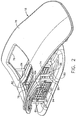
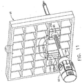
- a convention is used for locating a suspicious lesion by Cartesian coordinates within breast tissue referenced to the localization fixture 16 and to thereafter selectively position an instrument, such as a probe 90 ( FIG. 1 ) of a disposable probe assembly 91 that is engaged to the reusable holster portion 32 to form the MRI biopsy device 14.
- the MRI compatible biopsy system 10 may also guide a trocar ("introducer") 92 encompassed by a sleeve 94. Depth of insertion is controlled by a depth stop device 95 longitudinally positioned on either the probe 90 or the sleeve 94.
- a lateral fence depicted as a grid plate 96
- a laterally adjustable outer three sided plate bracket 98 attached below the left and right parallel upper guides 64, 66.
- a medial fence with respect to a medial plane of the chest of the patient depicted as a medial plate 100
- an inner three-sided plate bracket 102 attached below the left and right parallel upper guides 64, 66 close to the centerline pillars 82 when installed in the breast coil 18.
- a guide cube 104 is inserted into the backside of the grid plate 96.
- the selected breast is compressed along an inner (medial) side by the medial plate 100 and on an outside (lateral) side of the breast by the grid plate 96, the latter defining an X-Y plane.
- the X-axis is vertical (sagittal) with respect to a standing patient and corresponds to a left to right axis as viewed by a clinician facing the externally exposed portion of the localization fixture 16.
- Perpendicular to this X-Y plane extending toward the medial side of the breast is the Z-axis, which typically corresponds to the orientation and depth of insertion of the probe 90 of the MRI biopsy device 14 or the trocar/sleeve 92, 94.
- Z-axis may be used interchangeably with "axis of penetration", although the latter may or may not be orthogonal to the spatial coordinates used to locate an insertion point on the patient.
- Versions of the localization fixture 16 described herein allow a nonorthogonal axis of penetration to the X-Y axis to a lesion at a convenient or clinically beneficial angle.
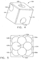
- guide cube 104 includes a central guide hole 106, a corner guide hole 108, and an off-center guide hole 110 that pass orthogonally to one another between respective opposite pairs of faces 112, 114, 116.
- guide cube 104 By selectively rotating the guide cube 104 in two axis, one of the pairs of faces 112, 114, 116 may be proximally aligned to an unturned position and then the selected proximal face 112, 114, 116 optionally rotated a quarter turn, half turn, or three quarter turn.
- one of nine guide positions 118 i.e., using central guide hole 106
- 120a-120d i.e., corner guide hole 108
- 122a-122d i.e., using off-center guide hole 110
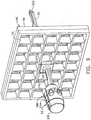
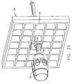
- the two-axis rotatable guide cube 104 is sized for insertion from a proximal side into one of a plurality of square recesses 130 in the grid plate 96 formed by intersecting vertical bars 132 and horizontal bars 134.
- the guide cube 104 is prevented from passing through the grid plate 96 by a backing substrate 136 attached to a front face of the grid plate 96.
- the backing substrate 136 includes a respective square opening 138 centered within each square recess 130, forming a lip 140 sufficient to capture the front face of the guide cube 104 but not so large as to obstruct the guide holes 104, 106, 108.
- the depth of the square recesses 130 is less than the guide cube 104, thereby exposing a proximal portion 142 of the guide cube 104 for seizing and extraction from the grid plate 96.
- the trocar 92 is slid into the sleeve 94 and the combination is guided through the guide cube 104 ( FIG. 9 ) to the biopsy site within the breast tissue.
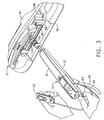
- the sleeve 94 includes a hollow shaft (or cannula) 196 that is proximally attached to a cylindrical hub 198 and has a lateral aperture 200 proximate to an open distal end 202.
- the cylindrical hub 198 has an exteriorly presented thumbwheel 204 for rotating the lateral aperture 200.
- the cylindrical hub 198 has an interior recess 206 that encompasses a duckbill seal 208, wiper seal 210 and a seal retainer 212 to provide a fluid seal when the shaft 196 is empty and for sealing to the inserted introducer (trocar) 92.
- Longitudinally spaced measurement indicia 213 along an outer surface of the hollow shaft 196 visually, and perhaps physically, provide a means to locate the depth stop device 95 of FIG. 1 .
- a hollow shaft 214 includes a fluid lumen 216 that communicates between an imagable side notch 218 and a proximal port 220.
- the hollow shaft 214 is longitudinally sized to extend, when fully engaged, a piercing tip 222 out of the distal end 202 of the sleeve 94.
- An obturator thumbwheel cap 224 encompasses the proximal port 220 and includes a locking feature 226, which includes a visible angle indicator 228 ( FIG. 8 ), that engages the sleeve thumbwheel 204 to ensure that the imagable side notch 218 is registered to the lateral aperture 200 in the sleeve 94.
- An obturator seal cap 230 may be engaged proximally into the obturator thumbwheel cap 224 to close the fluid lumen 216.
- the obturator seal cap 230 includes a locking or locating feature 232 that includes a visible angle indicator 233 that corresponds with the visible angle indicator 228 on the obturator thumbwheel cap 224, which may be fashioned from either a rigid, soft, or elastomeric material.
- the guide cube 104 has guided the trocar 92 and sleeve 94 through the grid plate 96.
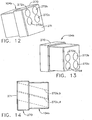
- an alternative guide cube 104a has rotation in two axes but is self grounding by means of an added rectangular prism 240 which has a shared edge with a cubic portion 242 of the guide cube 104a.
- a larger square face 244 of the cubic portion 242 overlaps with a smaller square face 246 of the rectangular prism 240 to correspond with the desired size of an exposed proximal portion 248 of the inserted guide cube 104a.
- the rectangular prism 240 allows proximal exposure of one of two adjacent faces 250, 252 of the guide cube 104a and then turning each to one of four quarter turn rotational positions.
- first face 250 has a central guide hole 106a and the second face 252 has a corner guide hole 108a, and an off-center guide hole 110a.
- a radial recess 254 is relieved into the rectangular prism 240 to allow grounding of the depth stop device 95 against the face 252 when the off-center guide hole 110a is used.
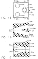
- another alternative guide cube 104b has a proximal enlarged hat portion 270 about a proximal face 271 that grounds against the selected square recess 130 in the grid plate 96 ( FIG. 6 ) and allows rotation about one axis to one of four quarter turn positions.
- Four angled guide holes 272a, 272b, 272c, 272d allow accessing not only an increased number of insertion points within the selected square recess 130 but also a desired angle of penetration rather than being constrained to a perpendicular insertion.
- an additional alternative guide cube 104c also has the proximal enlarged hat portion 270 about the proximal face 271 that grounds against the selected square recess 130 in the grid plate 96 ( FIG. 6 ) and allows rotation about one axis to one of four quarter turn positions.
- the guide holes are depicted as a first pair of converging angled through holes 310a, 310b having outwardly spaced proximal openings 311a, 311b ( FIG. 15 ), respectively, that communicate with partially intersecting distal openings 312a, 312b, respectively.
- the guide holes are also depicted as a second pair of diverging angled through holes 310c, 310d having partially intersecting proximal openings 311c, 311d, respectively, that communicate with outwardly spaced distal openings 312c, 312d.
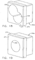
- a further alternative two-hole guide cube 104d has two enlarged guide holes 330, 332 accessed through the proximal face 271 in the enlarged proximal hat portion 270.
- a one hole guide cube 104e has one enlarged guide hole 334 accessed through the proximal face 271 in the enlarged proximal hat portion 270.
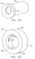
- Each guide cube 104d, 104e may receive a cylindrical rotating guide 336 ( FIG. 20 ) with an integral, proximal depth ring stop 338.
- a through hole 340 in the cylindrical guide 336 is sized to receive a biopsy instrument cannula (e.g., probe 90, sleeve 94) by being oval in cross section in the illustrative version.
- a biopsy instrument cannula e.g., probe 90, sleeve 94
- the cylindrical guide 336 may provide structural support to the guided portion of the biopsy instrument support as well as facilitate axial rotation thereof, especially for a non cylindrical biopsy instrument cannula.
- the two-hole and one-hole guide cubes 104d, 104e and rotating guide 336 may comprise a guide cube set, perhaps with additional guide cubes (not shown) having uniquely positioned guide holes.
- additional guide cubes not shown
- too much overlap of guide holes e.g., 330, 332
- fine positioning is accomplished by selecting one of the available guide cubes 104d, 104e for the desired position within a selected grid aperture.
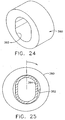
- a locking O-ring feature may be advantageously incorporated into a depth ring stop (rotating guide) 350. Having to rely upon constant frictional engagement of the depth ring stop (rotating guide) 350 alone would result in difficulty in installing the ring stop 350 to the desired position or being too readily displaced to serve as a stopping structure.
- an outer circumference surface 351 of the ring stop 350 includes left and right outer longitudinal ridges 352, 354 that aid in gripping and orienting the depth ring stop 350 while turning for locking and unlocking.
- opposing inner longitudinal ridges 356, 358 formed in a generally cylindrical inner diameter 359 abut respectively at an upper left and lower right side of an oval cannula 360 ( FIG. 23 ) oriented with its elongate cross section vertically in an unlocked position.
- the inner longitudinal ridges 356, 358 allow a quarter turn clockwise of the oval cannula, depicted as 360', to a locked position deforming an inner tangential locking rib 362.
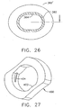
- a cylindrical rotating guide 380 formed of a resilient polymer, has an elongate through hole 382 shaped to permit insertion of an oval biopsy cannula 384.
- FIG. 24-25 a cylindrical rotating guide 380, formed of a resilient polymer, has an elongate through hole 382 shaped to permit insertion of an oval biopsy cannula 384.
- a rotating guide 400 is oval shaped with flattened elongate sides and with a corresponding elongate through hole 402.
- the outer shape may be tactile, advantageous for gripping as well as for providing a visual indication of being locked or unlocked.
- a resilient tangential rib 404 crossing one inner corner of the elongate through hole 402 is positioned to bind against an inserted biopsy instrument cannula (not shown) when the rotating guide 400 is turned a quarter turn to a locking position.
- a triangular clip depth stop 420 has a transverse front surface 422 with a proximally turned lower lip 424 and an upper lateral edge 426 attached to a downwardly and proximally ramped member 428 whose lower lateral edge 430 bends distally to form a horizontal locking actuator member 432 whose distal edge 434 rests upon the lower lip 424.
- a front vertically elongate aperture 436 in the transverse front surface 422 is shaped to approximate the outer diameter of an inserted biopsy instrument cannula (not shown).
- a scissor-like clip depth stop 450 is cut out of a layer of resilient material.
- an upper arm portion 452 and a lower arm portion 454 are attached to one radiating vertically away from each other toward the same lateral side (right as depicted) from a split cylindrical grasping portion 456 separated longitudinally on a lateral side opposite to the arm portions 452, 454 (left as depicted).
- an upper gripping half-cylindrical member 458 is attached at its right side to a lower portion 460 of the upper arm portion 452.
- a lower gripping half-cylindrical member 462 is attached at its right side to an upper portion 464 of the lower arm portion 454.
- An upper hemispheric portion 466 of the upper arm portion 452 includes an upper finger hole 468.
- a lower hemispheric portion 470 of the lower arm portion 454 includes a lower finger hole 472.
- a triangular recess 474 (opening rightward as depicted) formed by the arm portions 452, 454 and a longitudinal pin 476 inserted at the juncture between the arm portions 452, 454 predispose the arm portions 452, 454 to be resiliently drawn toward each other as the finger holes 468, 472 are gripped and moved together, thereby opening the upper and lower gripping half cylindrical members 458, 462, widening the separation of their left ends.
- a biopsy instrument cannula (not shown) may be inserted and positioned to a desired depth.
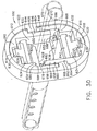
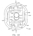
- a shuttered depth stop 600 includes a resilient oval shell 602 with a corresponding oval aperture 604 with an upper right tab 606 projecting inwardly to the left and with a lower left tab 608 projecting inwardly to the right when viewed from behind ( FIG. 30 ).
- An upper resilient member 610 has a generally horseshoe-shaped outer surface 612 that conforms to an upper portion 614 of the oval aperture 604.
- a lower resilient member 616 has a generally horseshoe-shaped outer surface 618 that conforms to a lower portion 620 of the oval aperture 604.
- the upper and lower resilient members 610, 616 are identical but are rotated a half turn about a longitudinal axis with respect to each other.
- the entire shuttered depth stop 600 is symmetric about its vertical axis defined by its longest dimension or about a horizontal axis defined by its second longest dimension.
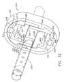
- a downwardly open rectangular prismatic recess 622 formed in the upper resilient member 610 is sized to receive an upper shutter 624 having an upper center tab 626 and a lower acute edge 628.
- a top center rectangular slot 630 formed in the upper resilient member 610 communicates with the downwardly open rectangular prismatic recess 622 and receives the upper center tab 626.
- An upwardly open rectangular prismatic recess 632 formed in the lower resilient member 616 is sized to receive a lower shutter 634 having a lower center tab 636 and an upper acute edge 638.
- a bottom center rectangular slot 639 formed in the lower resilient member 616 communicates with the upwardly open rectangular prismatic recess 632 and receives the lower center tab 636.
- An upper horizontal pin 640 attached horizontally as depicted across the upper shutter 624 is received for rotation onto opposite lateral sides of the downwardly open rectangular prismatic recess 622.
- a lower horizontal pin 642 attached horizontally as depicted across the lower shutter 634 is received for rotation onto opposite lateral sides of the upwardly open rectangular prismatic recess 632.
- the right side of the upper resilient member 610 includes a right outward shoulder 644 that rests upon the upper right tab 606 of the resilient oval shell 602.
- a laterally recessed downward arm 646 is attached to the right shoulder 644 and extends downwardly with its outer surface 648 vertically aligned with an innermost edge 650 of the right outward shoulder 644 and with its inner surface 652 defining the downwardly open generally rectangular prismatic recess 622.
- the left side of the upper resilient member 610 includes a left inward shoulder 654 that is laterally aligned with and opposite of the upper right tab 606 of the resilient oval shell 602.
- An outer downward arm 656 is attached to the left inward shoulder 654 and extends downwardly with its outer surface 658 against oval aperture 604 and an innermost edge 660 vertically aligned with an inner surface 662 of the lower left tab 608 upon which the outer downward arm 656 rests.
- the lower resilient member 616 includes a left outward shoulder 664 attached to a laterally recessed upward arm 666 and a right inward shoulder 668 attached to an outer upward arm 670 that abuts an underside of the upper right tab 606.
- the laterally recessed downward arm 646 of the upper resilient member 610 extends downward past the longitudinal centerline of the shuttered depth stop 600 and an inserted biopsy instrument cannula 672.
- a lower edge 674 of the laterally recessed downward arm 646 is spaced away from an upper surface 676 of the right inward shoulder 668.
- an upper edge 678 of the laterally recessed upward arm 666 is spaced away from a lower surface 680 of the left inward shoulder 654.
- this spacing between the left inward shoulder 654 and the upper edge 678 of the laterally recessed upward arm 666 defines an upper left rectangular recess 682 communicating rightward into the downwardly open rectangular prismatic recess 622 and sized to allow unimpeded swinging of a leftward extension 684 of the upper shutter 624.
- Spacing between the upper surface 676 of the right inward shoulder 668 and the lower edge 674 of the laterally recessed downward arm 646 defines a lower right rectangular recess 686 which communicates leftward into the upwardly open rectangular prismatic recess 632 which is sized to allow unimpeded swinging of a rightward extension 688 of the lower shutter 634.
- the shuttered depth stop 600 initially has closed upper and lower shutters 624, 634 due to restoring pressure from the top center rectangular slot 630 on the upper center tab 626 and from the bottom center rectangular slot 639 on the lower center tab 636 respectively. Insertion of a biopsy instrument cannula 672 from a selected side (thus the aft side) causes the upper and lower acute edges 628, 638 of the shutters 624, 634 to swing distally and outwardly but remain in contact due to the restoring pressure previously mentioned.
- Proximal retraction of the biopsy instrument cannula 672 frictionally rotates the acute edges 628, 638 proximally, and thus inwardly, binding upon the biopsy instrument cannula 672 preventing inadvertent retraction to serve as a depth stop.
- squeezing the resilient oval shell 602 to reduce the vertical height of the shutter depth stop 600 in FIG. 33 causes the laterally recessed downward arm 646 to open the lower shutter 634 and the laterally recessed upward arm 666 to open the upper shutter 624.
- straight upper and lower acute edges 628, 638 of the two shutters 624, 634 may instead be contoured to closely approximate the transverse cross section of the encompassed shuttered depth stop 600 to increase the locking against inadvertent retraction.
- a grid plate 96 with a backing lip 140 may be used such that a guide cube rotatable to each of the six faces with four quarter turn positions for each face may achieve a large number of possible insertion positions and angles of insertion.
- biasing of the locking / unlocking components of various versions of a depth stop for a biopsy cannula described herein are advantageously formed out of an elastomeric material for economical manufacture.
- an assembly of rigid components biased by springs for biasing and/or actuating controls to move the locking surface out of engagement may be substituted to achieve similar results consistent with aspects of the present invention.
- the positioning and height of a central web of a breast coil may enable use of a medial grid plate used with a rotatable cube and penetrate from the medial side of the breast.
- a grid having a different geometric shape, such as hexagonal may be employed.
- each grid aperture of equilateral polygonal lateral cross section in a grid plate taper toward their distal opening to ground a similarly tapered guide block.
Landscapes
- Health & Medical Sciences (AREA)
- Life Sciences & Earth Sciences (AREA)
- Surgery (AREA)
- Animal Behavior & Ethology (AREA)
- Public Health (AREA)
- Engineering & Computer Science (AREA)
- Biomedical Technology (AREA)
- Heart & Thoracic Surgery (AREA)
- Medical Informatics (AREA)
- Molecular Biology (AREA)
- Pathology (AREA)
- General Health & Medical Sciences (AREA)
- Veterinary Medicine (AREA)
- Nuclear Medicine, Radiotherapy & Molecular Imaging (AREA)
- Oncology (AREA)
- Physics & Mathematics (AREA)
- Biophysics (AREA)
- Surgical Instruments (AREA)
- Magnetic Resonance Imaging Apparatus (AREA)
- High Energy & Nuclear Physics (AREA)
- Radiology & Medical Imaging (AREA)
Claims (6)
- Vorrichtung zur Verwendung mit einer Biopsiekanüle mit einem langgestreckten transversalen Querschnitt, wobei die Vorrichtung folgendes umfasst:einen Führungsabschnitt (104), der eine Schaftöffnung (106) definiert, die eine derartige Größe aufweist, dass sie die Biopsiekanüle aufnimmt und zumindest teilweise um deren Umfang umgibt, wobei die Schaftanordnung dazu ausgelegt ist, eine relative Längsbewegung der Biopsiekanüle zu gestatten, wenn sich die Biopsiekanüle in einer ersten Winkelorientierung befindet; undein Verriegelungselement (350, 400), das ein langgestrecktes Durchgangsloch (359, 402) definiert, das zur Aufnahme der Biopsiekanüle (360) ausgelegt ist, wobei das Verriegelungselement eine Rippe (362, 404) umfasst, die sich einwärts und tangential im Durchgangsloch erstreckt, wobei die Rippe dazu ausgelegt ist, bei einer relativen Drehung der Biopsiekanüle und des Verriegelungselements in eine Verriegelungsposition, in der sich die Biopsiekanüle in einer zweiten Winkelorientierung befindet, und die sich von der ersten Winkelorientierung unterscheidet, an der Biopsiekanüle festzulaufen,wobei das Verriegelungselement als Tiefenanschlag dient, der dazu ausgelegt ist, die Einführungstiefe der Biopsiekanüle durch den Führungsabschnitt zu begrenzen, wenn die Rippe des Verriegelungselements in der Verriegelungsposition an der Biopsiekanüle festgelaufen ist.
- Vorrichtung nach Anspruch 1, wobei das Verriegelungselement abgeflachte langgestreckte Seiten aufweist.
- Vorrichtung nach Anspruch 1, wobei das langgestreckte Durchgangsloch eine innere Ecke aufweist, wobei die Rippe die innere Ecke überquert.
- Vorrichtung nach Anspruch 1, wobei das Verriegelungselement und die Biopsiekanüle nach ungefähr einer Vierteldrehung der relativen Drehung zwischen der Biopsiekanüle und dem Verriegelungselement die Verriegelungsposition erreichen.
- Vorrichtung nach Anspruch 1, wobei der Führungsabschnitt einen Würfel (104) mit einem rechteckigen Prisma neben mindestens zwei Flächen des Würfels aufweist.
- Vorrichtung nach Anspruch 5, wobei der Würfel eine Vielzahl von Öffnungen aufweist, die dazu ausgelegt sind, die Biopsiekanüle in einer Vielzahl von Orientierungen durch den Würfel zu führen.
Priority Applications (1)
| Application Number | Priority Date | Filing Date | Title |
|---|---|---|---|
| EP17179618.8A EP3263041A1 (de) | 2006-05-01 | 2007-04-30 | Biopsienadel mit einstellbarem tiefenstopp |
Applications Claiming Priority (2)
| Application Number | Priority Date | Filing Date | Title |
|---|---|---|---|
| US11/414,988 US7507210B2 (en) | 2006-05-01 | 2006-05-01 | Biopsy cannula adjustable depth stop |
| EP07251810A EP1852070B1 (de) | 2006-05-01 | 2007-04-30 | Biopsienadel mit einstellbarem Tiefenstopp |
Related Parent Applications (1)
| Application Number | Title | Priority Date | Filing Date |
|---|---|---|---|
| EP07251810A Division EP1852070B1 (de) | 2006-05-01 | 2007-04-30 | Biopsienadel mit einstellbarem Tiefenstopp |
Related Child Applications (1)
| Application Number | Title | Priority Date | Filing Date |
|---|---|---|---|
| EP17179618.8A Division EP3263041A1 (de) | 2006-05-01 | 2007-04-30 | Biopsienadel mit einstellbarem tiefenstopp |
Publications (2)
| Publication Number | Publication Date |
|---|---|
| EP2111799A1 EP2111799A1 (de) | 2009-10-28 |
| EP2111799B1 true EP2111799B1 (de) | 2017-07-05 |
Family
ID=38283261
Family Applications (3)
| Application Number | Title | Priority Date | Filing Date |
|---|---|---|---|
| EP17179618.8A Withdrawn EP3263041A1 (de) | 2006-05-01 | 2007-04-30 | Biopsienadel mit einstellbarem tiefenstopp |
| EP07251810A Not-in-force EP1852070B1 (de) | 2006-05-01 | 2007-04-30 | Biopsienadel mit einstellbarem Tiefenstopp |
| EP09075358.3A Active EP2111799B1 (de) | 2006-05-01 | 2007-04-30 | Biopsienadel mit einstellbarem Tiefenstopp |
Family Applications Before (2)
| Application Number | Title | Priority Date | Filing Date |
|---|---|---|---|
| EP17179618.8A Withdrawn EP3263041A1 (de) | 2006-05-01 | 2007-04-30 | Biopsienadel mit einstellbarem tiefenstopp |
| EP07251810A Not-in-force EP1852070B1 (de) | 2006-05-01 | 2007-04-30 | Biopsienadel mit einstellbarem Tiefenstopp |
Country Status (8)
| Country | Link |
|---|---|
| US (3) | US7507210B2 (de) |
| EP (3) | EP3263041A1 (de) |
| JP (3) | JP5165920B2 (de) |
| CN (1) | CN101066214B (de) |
| AU (1) | AU2007201670B2 (de) |
| CA (2) | CA2940399A1 (de) |
| DE (1) | DE602007001999D1 (de) |
| HK (1) | HK1248506A1 (de) |
Families Citing this family (95)
| Publication number | Priority date | Publication date | Assignee | Title |
|---|---|---|---|---|
| US7379769B2 (en) | 2003-09-30 | 2008-05-27 | Sunnybrook Health Sciences Center | Hybrid imaging method to monitor medical device delivery and patient support for use in the method |
| US7740593B2 (en) | 2005-12-09 | 2010-06-22 | Senorx, Inc | Guide block for biopsy or surgical devices |
| US8579807B2 (en) | 2008-04-28 | 2013-11-12 | Ethicon Endo-Surgery, Inc. | Absorbing fluids in a surgical access device |
| US7507210B2 (en) | 2006-05-01 | 2009-03-24 | Ethicon Endo-Surgery, Inc. | Biopsy cannula adjustable depth stop |
| US20140039343A1 (en) | 2006-12-13 | 2014-02-06 | Devicor Medical Products, Inc. | Biopsy system |
| US8702623B2 (en) | 2008-12-18 | 2014-04-22 | Devicor Medical Products, Inc. | Biopsy device with discrete tissue chambers |
| US8290569B2 (en) | 2007-11-23 | 2012-10-16 | Hologic, Inc. | Open architecture tabletop patient support and coil system |
| US8374676B2 (en) * | 2007-11-23 | 2013-02-12 | Hologic, Inc. | Chest wall coil array for breast imaging |
| US20090209853A1 (en) | 2008-02-19 | 2009-08-20 | Parihar Shailendra K | Biopsy site marker applier |
| AU2009201610A1 (en) | 2008-04-23 | 2009-11-19 | Devicor Medical Products, Inc. | PEM and BSGI biopsy devices and methods |
| US8864681B2 (en) * | 2008-04-23 | 2014-10-21 | Devicor Medical Products, Inc. | Biopsy devices |
| US20090270726A1 (en) | 2008-04-23 | 2009-10-29 | Leimbach Jessica P | Methods For Imaging |
| US8532748B2 (en) | 2008-04-23 | 2013-09-10 | Devicor Medical Products, Inc. | Devices useful in imaging |
| US8273060B2 (en) | 2008-04-28 | 2012-09-25 | Ethicon Endo-Surgery, Inc. | Fluid removal in a surgical access device |
| US11235111B2 (en) | 2008-04-28 | 2022-02-01 | Ethicon Llc | Surgical access device |
| USD700326S1 (en) * | 2008-04-28 | 2014-02-25 | Ethicon Endo-Surgery, Inc. | Trocar housing |
| US8636686B2 (en) | 2008-04-28 | 2014-01-28 | Ethicon Endo-Surgery, Inc. | Surgical access device |
| US8870747B2 (en) * | 2008-04-28 | 2014-10-28 | Ethicon Endo-Surgery, Inc. | Scraping fluid removal in a surgical access device |
| US8568362B2 (en) | 2008-04-28 | 2013-10-29 | Ethicon Endo-Surgery, Inc. | Surgical access device with sorbents |
| US9358041B2 (en) | 2008-04-28 | 2016-06-07 | Ethicon Endo-Surgery, Llc | Wicking fluid management in a surgical access device |
| US20090292224A1 (en) * | 2008-05-22 | 2009-11-26 | Bowman Bryan J | Positioning mechanism for an introducer device |
| US8057432B2 (en) * | 2008-05-22 | 2011-11-15 | Suros Surgical Systems, Inc. | Selective locking mechanism for an introducer device |
| US7730628B2 (en) * | 2008-09-05 | 2010-06-08 | Bayer Schering Pharma Ag | Depth stop devices and systems |
| US7846109B2 (en) * | 2008-12-18 | 2010-12-07 | Devicor Medical Products, Inc. | Biopsy device with sliding cutter cover |
| US20100160811A1 (en) | 2008-12-18 | 2010-06-24 | Parihar Shailendra K | Z-Stop Feature of Targeting Set for MRI Biopsy Device |
| US20100160822A1 (en) * | 2008-12-18 | 2010-06-24 | Parihar Shailendra K | Biopsy Device with Detachable Needle |
| US7862518B2 (en) | 2008-12-18 | 2011-01-04 | Devicor Medical Products, Inc. | Biopsy device with telescoping cutter cover |
| US8460206B2 (en) * | 2008-12-18 | 2013-06-11 | Devicor Medical Products, Inc. | Multi-orientation targeting set for MRI biopsy device |
| US9398922B2 (en) * | 2008-12-18 | 2016-07-26 | Devicor Medical Products, Inc. | Targeting set for MRI biopsy device with probe holster support |
| US8328732B2 (en) | 2008-12-18 | 2012-12-11 | Devicor Medical Products, Inc. | Control module interface for MRI biopsy device |
| US8167815B2 (en) * | 2008-12-18 | 2012-05-01 | Devicor Medical Products, Inc. | Biopsy device with retractable cutter |
| US8366635B2 (en) | 2008-12-18 | 2013-02-05 | Devicor Medical Products, Inc. | Biopsy probe and targeting set interface |
| EP2403410B1 (de) * | 2009-03-06 | 2018-10-31 | Hologic Inc. | Paddelsystem für nadelbiopsiekompression |
| US8167814B2 (en) * | 2009-06-16 | 2012-05-01 | Devicor Medical Products, Inc. | Biopsy targeting cube with malleable members |
| US8197495B2 (en) * | 2009-06-16 | 2012-06-12 | Devicor Medical Products, Inc. | Biopsy targeting cube with elastomeric edges |
| US8858537B2 (en) | 2009-06-16 | 2014-10-14 | Devicor Medical Products, Inc. | Biopsy targeting cube with living hinges |
| US8366634B2 (en) * | 2009-06-16 | 2013-02-05 | Devicor Medical Products, Inc. | Biopsy targeting cube with elastomeric body |
| US8241302B2 (en) * | 2009-06-16 | 2012-08-14 | Devicor Medical Products, Inc. | Biopsy targeting cube with angled interface |
| US8206314B2 (en) | 2009-06-17 | 2012-06-26 | Devicor Medical Products, Inc. | MRI biopsy targeting grid with round openings |
| US20100324444A1 (en) * | 2009-06-17 | 2010-12-23 | Mollere Rebecca J | MRI Biopsy Targeting Grid Wall Guide |
| US20100324445A1 (en) * | 2009-06-17 | 2010-12-23 | Mollere Rebecca J | MRI Biopsy Cylindraceous Targeting Guide |
| WO2010148503A1 (en) * | 2009-06-23 | 2010-12-29 | Sentinelle Medical Inc. | Variable angle guide holder for a biopsy guide plug |
| US8529465B2 (en) * | 2009-09-24 | 2013-09-10 | Devicor Medical Products, Inc. | Biopsy marker delivery devices and methods |
| US20110071391A1 (en) * | 2009-09-24 | 2011-03-24 | Speeg Trevor W V | Biopsy marker delivery device with positioning component |
| US20110082364A1 (en) * | 2009-10-05 | 2011-04-07 | Hibner John A | MRI Biopsy Targeting Cube with Retention Wiper |
| US8162849B2 (en) * | 2009-10-16 | 2012-04-24 | Devicor Medical Products, Inc. | MRI biopsy targeting cube with gripping arms |
| US20110092850A1 (en) * | 2009-10-16 | 2011-04-21 | Kulkarni Abhijit G | MRI Biopsy Targeting Guide with Rotational Lock |
| US8162847B2 (en) * | 2009-10-16 | 2012-04-24 | Devicor Medical Products, Inc. | MRI biopsy targeting cube with snap corners |
| US8162848B2 (en) * | 2009-10-16 | 2012-04-24 | Devicor Medical Products, Inc. | MRI biopsy targeting cube with eccentric lock |
| EP2503934B1 (de) * | 2009-11-27 | 2021-10-20 | Hologic, Inc. | Systeme und verfahren zur verfolgung von positionen zwischen bildgebungsmodalitäten und umwandlung eines angezeigten dreidimensionalen bildes entsprechend einer position sowie ausrichtung einer sonde |
| US8597203B2 (en) | 2010-03-30 | 2013-12-03 | Siteselect Medical Technologies, Inc. | Tissue excision device with a reduced diameter cannula |
| US9332926B2 (en) | 2010-11-25 | 2016-05-10 | Invivo Corporation | MRI imaging probe |
| US9414816B2 (en) | 2011-06-23 | 2016-08-16 | Devicor Medical Products, Inc. | Introducer for biopsy device |
| US10159456B2 (en) | 2011-11-22 | 2018-12-25 | Ge Medical Systems Israel, Ltd | Systems and methods for biopsy guidance using a biopsy unit including at least one of an imaging detector or ultrasound probe concurrently mounted with a biopsy guide |
| WO2013158072A1 (en) * | 2012-04-16 | 2013-10-24 | Hathaway Jeff M | Biopsy device |
| KR102158322B1 (ko) | 2012-11-21 | 2020-09-22 | 씨. 알. 바드, 인크. | 코어 바늘 생검 디바이스 |
| USD735332S1 (en) | 2013-03-06 | 2015-07-28 | C. R. Bard, Inc. | Biopsy device |
| USD737440S1 (en) | 2013-03-07 | 2015-08-25 | C. R. Bard, Inc. | Biopsy device |
| US10092276B2 (en) | 2013-03-15 | 2018-10-09 | Cook Medical Technologies Llc | Tissue acquisition device with indication system |
| ES2961685T3 (es) | 2013-03-15 | 2024-03-13 | Hologic Inc | Sistema y método de revisión y análisis de muestras citológicas |
| USD735333S1 (en) | 2013-06-26 | 2015-07-28 | C. R. Bard, Inc. | Biopsy device |
| CA2918704A1 (en) | 2013-07-19 | 2015-01-22 | Devicor Medical Products, Inc. | Biopsy device targeting features |
| CN106456140B (zh) * | 2014-05-01 | 2019-08-13 | 德威科医疗产品公司 | 用于活检装置的导引器 |
| EP3148471B1 (de) * | 2014-05-28 | 2021-11-03 | General Electric Company | Verfahren und zugehörige biopsievorrichtung |
| US9974500B2 (en) | 2014-07-11 | 2018-05-22 | Ge Medical Systems Israel, Ltd. | Systems and methods for open imaging |
| KR102291496B1 (ko) | 2014-09-24 | 2021-08-20 | 데비코어 메디컬 프로덕츠, 인코포레이티드 | Mri 생체 검사 시스템 |
| WO2016179145A1 (en) | 2015-05-06 | 2016-11-10 | Devicor Medical Products, Inc. | Mri guided breast biopsy targeting assembly with obturator overshoot feature |
| WO2016179147A1 (en) | 2015-05-06 | 2016-11-10 | Devicor Medical Products, Inc. | Marker delivery device for use with mri breast biopsy system |
| US11147541B2 (en) | 2015-06-11 | 2021-10-19 | Devicor Medical Products, Inc. | MRI biopsy sample |
| WO2017019780A1 (en) | 2015-07-29 | 2017-02-02 | Devicor Medical Products, Inc. | Biopsy imaging rod with an egress port, with a biopsy marker and with a biased pushrod |
| US20180325502A1 (en) | 2015-08-31 | 2018-11-15 | Devicor Medical Products, Inc. | Multi-faceted needle tip and method of manufacturing |
| US10335124B1 (en) | 2016-02-29 | 2019-07-02 | Devicor Medical Products, Inc. | Marker delivery device with adaptor for biopsy site marking and method of use thereof |
| US20170311932A1 (en) * | 2016-04-29 | 2017-11-02 | Devicor Medical Products, Inc. | Depth stop device for use with biopsy targeting assembly |
| US20170311933A1 (en) | 2016-04-29 | 2017-11-02 | Devicor Medical Products, Inc. | Mri guided biopsy targeting set with firing obturator |
| US10357326B1 (en) * | 2016-07-29 | 2019-07-23 | Devicor Medical Products, Inc. | MRI breast biopsy targeting grid and cube |
| US10729856B1 (en) | 2016-07-29 | 2020-08-04 | Devicor Medical Products, Inc. | Guide and filter for biopsy device |
| US11160538B2 (en) | 2016-10-31 | 2021-11-02 | Devicor Medical Products, Inc. | Biopsy device with linear actuator |
| US20190029758A1 (en) | 2017-05-22 | 2019-01-31 | Devicor Medical Products, Inc. | Mri targeting set with improved targeting sleeve |
| EP3684267B1 (de) * | 2017-09-20 | 2023-03-22 | Devicor Medical Products, Inc. | Mrt geführtes biopsiegerät mit tiefenbegrenzung durch drehung |
| CN111601555A (zh) | 2017-11-22 | 2020-08-28 | Devicor医疗产业收购公司 | 用于mri引导的活检过程的可调节靶向套件 |
| CN111432734B (zh) | 2017-11-30 | 2024-05-28 | 巴德股份有限公司 | 用于活检装置的试样容器和同轴引入器插管 |
| US12186879B2 (en) * | 2018-01-18 | 2025-01-07 | Ingersoll-Rand Industrial U.S., Inc. | Add-on user interface module for precision power tools |
| US11723633B2 (en) | 2018-07-13 | 2023-08-15 | Devicor Medical Products, Inc. | Biopsy device with self-reversing cutter drive |
| US20200205855A1 (en) * | 2019-01-02 | 2020-07-02 | Covidien Lp | Surgical access device and sleeve stops for use therewith |
| US11344309B2 (en) * | 2019-07-05 | 2022-05-31 | Covidien Lp | Circular stapling instruments |
| CN112402029B (zh) * | 2019-08-23 | 2025-08-19 | 深圳钮迈科技有限公司 | 肿瘤治疗仪前面板、前面板组件和肿瘤治疗仪 |
| US11712267B2 (en) * | 2020-05-01 | 2023-08-01 | Cilag Gmbh International | Tilting tang cannula depth limiter |
| US11633211B2 (en) | 2020-05-01 | 2023-04-25 | Cilag Gmbh International | Pinch to release cannula depth limiter |
| US12402912B2 (en) | 2020-05-01 | 2025-09-02 | Cilag Gmbh International | Multi-diameter cannula depth limiter |
| US11986215B2 (en) | 2020-05-01 | 2024-05-21 | Cilag Gmbh International | Universal size multi-walled elastomer cannula depth limiter |
| US12213699B2 (en) | 2020-05-01 | 2025-02-04 | Cilag Gmbh International | Threaded cannula depth limiter |
| US11980392B2 (en) | 2020-05-01 | 2024-05-14 | Cilag Gmbh International | Pinch-to-clamp cannula depth limiter |
| US12426896B2 (en) | 2020-08-07 | 2025-09-30 | Mighty Oak Medical, Inc. | Drilling depth and control apparatus and methods for using the same |
| US11529147B2 (en) | 2020-08-07 | 2022-12-20 | Mighty Oak Medical, Inc. | Drilling depth and control apparatus and methods for using the same |
| CN115445039B (zh) * | 2022-09-19 | 2023-09-29 | 无锡仁诺科技发展有限公司 | 自动位移自动搜寻声门并置入气管导管的智能插管系统 |
Citations (2)
| Publication number | Priority date | Publication date | Assignee | Title |
|---|---|---|---|---|
| US4610672A (en) * | 1985-06-10 | 1986-09-09 | Sherwood Medical Company | Syringe locking device |
| US5056523A (en) * | 1989-11-22 | 1991-10-15 | Board Of Regents, The University Of Texas System | Precision breast lesion localizer |
Family Cites Families (80)
| Publication number | Priority date | Publication date | Assignee | Title |
|---|---|---|---|---|
| DE3429074C2 (de) * | 1984-08-07 | 1986-12-11 | Simro AG, Meilen | Brillengestell und Teile davon |
| GB2171444A (en) * | 1984-11-21 | 1986-08-28 | Kenneth Johnstone Hume | Clamp for telescopic tubes |
| DE3445930A1 (de) | 1984-12-17 | 1986-06-26 | Cassella Ag, 6000 Frankfurt | Farbstoffmischungen, verfahren zu ihrer herstellung und verfahren zum faerben und bedrucken von hydrophoben fasermaterialien |
| SU1537232A1 (ru) * | 1987-04-13 | 1990-01-23 | Днепропетровский медицинский институт | Устройство дл биопсии тканей |
| US4924878A (en) * | 1988-11-07 | 1990-05-15 | Nottke James E | Actuating mechanism for biopsy needle |
| US5217441A (en) | 1989-08-15 | 1993-06-08 | United States Surgical Corporation | Trocar guide tube positioning device |
| CA2055486C (en) * | 1989-11-27 | 1996-11-26 | Anders Magnusson | Puncture guide for computer tomography |
| JP2577132B2 (ja) * | 1990-11-13 | 1997-01-29 | アロカ株式会社 | 超音波探触子用穿刺アダプタ |
| CA2037511A1 (en) | 1991-03-04 | 1992-09-05 | Daniel Assh | System for control of the condition of mixed concrete |
| CN2142325Y (zh) * | 1992-06-28 | 1993-09-22 | 梁季鸿 | 多用途负压旋切活检针 |
| US5437603A (en) | 1993-09-14 | 1995-08-01 | C.R. Bard, Inc. | Apparatus and method for implanting prostheses within periurethral tissues |
| US5526822A (en) | 1994-03-24 | 1996-06-18 | Biopsys Medical, Inc. | Method and apparatus for automated biopsy and collection of soft tissue |
| US5649547A (en) | 1994-03-24 | 1997-07-22 | Biopsys Medical, Inc. | Methods and devices for automated biopsy and collection of soft tissue |
| JP3394327B2 (ja) * | 1994-07-11 | 2003-04-07 | テルモ株式会社 | チューブの内面処理方法 |
| JPH10508504A (ja) | 1994-09-16 | 1998-08-25 | バイオプシス メディカル インコーポレイテッド | 組織を特定しおよびマーキングする方法および装置 |
| DE4442609C1 (de) * | 1994-11-30 | 1996-08-08 | Siemens Ag | Stereotaktische Zusatzeinrichtung zur schnittbildgeführten Durchführung einer Biopsie |
| US5713869A (en) | 1995-03-08 | 1998-02-03 | Morejon; Orlando | Trocar assembly |
| US5660185A (en) * | 1995-04-13 | 1997-08-26 | Neovision Corporation | Image-guided biopsy apparatus with enhanced imaging and methods |
| US5706812A (en) | 1995-11-24 | 1998-01-13 | Diagnostic Instruments, Inc. | Stereotactic MRI breast biopsy coil and method for use |
| US5769086A (en) | 1995-12-06 | 1998-06-23 | Biopsys Medical, Inc. | Control system and method for automated biopsy device |
| US5810712A (en) * | 1996-09-27 | 1998-09-22 | Ohio Medical Instrument Company, Inc. | Surgical endoscope support and pivot |
| US5984930A (en) | 1996-09-30 | 1999-11-16 | George S. Allen | Biopsy guide |
| US5855554A (en) * | 1997-03-17 | 1999-01-05 | General Electric Company | Image guided breast lesion localization device |
| US6017316A (en) | 1997-06-18 | 2000-01-25 | Biopsys Medical | Vacuum control system and method for automated biopsy device |
| US6616630B1 (en) * | 1997-08-20 | 2003-09-09 | B. Braun Melsungen A.G. | Spring clip safety IV catheter |
| DE69828011T2 (de) * | 1997-09-26 | 2005-12-01 | Koninklijke Philips Electronics N.V. | Vorrichtung zur Halterung eines chirurgischen Instruments |
| JP4131508B2 (ja) * | 1997-11-14 | 2008-08-13 | ボストン サイエンティフィック リミテッド | マルチ−シース送達カテーテル |
| US6077230A (en) | 1998-05-14 | 2000-06-20 | Ethicon Endo-Surgery, Inc. | Biopsy instrument with removable extractor |
| US5964716A (en) | 1998-05-14 | 1999-10-12 | Ethicon Endo-Surgery, Inc. | Method of use for a multi-port biopsy instrument |
| US6007497A (en) | 1998-06-30 | 1999-12-28 | Ethicon Endo-Surgery, Inc. | Surgical biopsy device |
| CA2287087C (en) | 1998-10-23 | 2007-12-04 | Ethicon Endo-Surgery, Inc. | Surgical device for the collection of soft tissue |
| EP1027867A1 (de) | 1999-02-09 | 2000-08-16 | Berger AG | Vorrichtung zum Halten einer Hülse und Verfahren zum Herstellen einer solchen Vorrichtung |
| US6086544A (en) | 1999-03-31 | 2000-07-11 | Ethicon Endo-Surgery, Inc. | Control apparatus for an automated surgical biopsy device |
| US6120462A (en) | 1999-03-31 | 2000-09-19 | Ethicon Endo-Surgery, Inc. | Control method for an automated surgical biopsy device |
| US6210417B1 (en) * | 1999-04-29 | 2001-04-03 | Medtronic, Inc. | Medical lead positioning and anchoring system |
| US6162187A (en) | 1999-08-02 | 2000-12-19 | Ethicon Endo-Surgery, Inc. | Fluid collection apparatus for a surgical device |
| US6428487B1 (en) | 1999-12-17 | 2002-08-06 | Ethicon Endo-Surgery, Inc. | Surgical biopsy system with remote control for selecting an operational mode |
| US6432065B1 (en) | 1999-12-17 | 2002-08-13 | Ethicon Endo-Surgery, Inc. | Method for using a surgical biopsy system with remote control for selecting and operational mode |
| US6231522B1 (en) | 2000-02-18 | 2001-05-15 | Ethicon Endo-Surgery, Inc. | Biopsy instrument with breakable sample segments |
| US6500109B2 (en) * | 2000-07-21 | 2002-12-31 | Tayman Medical, Inc. | Prostate treatment template |
| US6317575B1 (en) * | 2000-08-15 | 2001-11-13 | Xerox Corporation | Firm interlock between shaft and bore |
| US6602203B2 (en) | 2000-10-13 | 2003-08-05 | Ethicon Endo-Surgery, Inc. | Remote thumbwheel for a surgical biopsy device |
| DE10122241A1 (de) | 2001-05-08 | 2002-12-05 | Bosch Gmbh Robert | Kraftstoffeinspritzventil für Brennkraftmaschinen |
| DE10138707C2 (de) * | 2001-08-07 | 2003-10-16 | Siemens Ag | Vorrichtung zur endorektalen Prostatabiopsie |
| US6626849B2 (en) | 2001-11-01 | 2003-09-30 | Ethicon Endo-Surgery, Inc. | MRI compatible surgical biopsy device |
| US7826883B2 (en) | 2002-04-23 | 2010-11-02 | Devicor Medical Products, Inc. | Localization mechanism for an MRI compatible biopsy device |
| US20030199753A1 (en) | 2002-04-23 | 2003-10-23 | Ethicon Endo-Surgery | MRI compatible biopsy device with detachable probe |
| US7769426B2 (en) | 2002-04-23 | 2010-08-03 | Ethicon Endo-Surgery, Inc. | Method for using an MRI compatible biopsy device with detachable probe |
| US20040064149A1 (en) | 2002-09-23 | 2004-04-01 | Doern Frederick E. | Probe holder to facilitate fibre optic examination of tissue surfaces |
| US7559927B2 (en) * | 2002-12-20 | 2009-07-14 | Medtronic Xomed, Inc. | Surgical instrument with telescoping attachment |
| US7244234B2 (en) | 2003-11-11 | 2007-07-17 | Soma Development Llc | Ultrasound guided probe device and method of using same |
| US7607878B2 (en) * | 2004-05-10 | 2009-10-27 | Thomas & Betts International, Inc. | Anti-vibration/rotation device for split bolts |
| US7708751B2 (en) | 2004-05-21 | 2010-05-04 | Ethicon Endo-Surgery, Inc. | MRI biopsy device |
| DE602005017037D1 (de) * | 2004-05-21 | 2009-11-19 | Ethicon Endo Surgery Inc | Mrt-biopsiegerät mit einem darstellbaren penetrierenden teil |
| US9638770B2 (en) * | 2004-05-21 | 2017-05-02 | Devicor Medical Products, Inc. | MRI biopsy apparatus incorporating an imageable penetrating portion |
| US7846103B2 (en) * | 2004-09-17 | 2010-12-07 | Medical Equipment Diversified Services, Inc. | Probe guide for use with medical imaging systems |
| US20060074345A1 (en) | 2004-09-29 | 2006-04-06 | Hibner John A | Biopsy apparatus and method |
| US7744606B2 (en) * | 2004-12-04 | 2010-06-29 | Medtronic, Inc. | Multi-lumen instrument guide |
| US20060241385A1 (en) * | 2005-04-12 | 2006-10-26 | Ethicon Endo-Surgery, Inc. | Guided disposable fiducial for breast biopsy localization fixture |
| US7854707B2 (en) | 2005-08-05 | 2010-12-21 | Devicor Medical Products, Inc. | Tissue sample revolver drum biopsy device |
| US7740593B2 (en) * | 2005-12-09 | 2010-06-22 | Senorx, Inc | Guide block for biopsy or surgical devices |
| US7507210B2 (en) | 2006-05-01 | 2009-03-24 | Ethicon Endo-Surgery, Inc. | Biopsy cannula adjustable depth stop |
| US8568333B2 (en) | 2006-05-01 | 2013-10-29 | Devicor Medical Products, Inc. | Grid and rotatable cube guide localization fixture for biopsy device |
| US7938786B2 (en) | 2006-12-13 | 2011-05-10 | Devicor Medical Products, Inc. | Vacuum timing algorithm for biopsy device |
| US8702623B2 (en) | 2008-12-18 | 2014-04-22 | Devicor Medical Products, Inc. | Biopsy device with discrete tissue chambers |
| US9345457B2 (en) | 2006-12-13 | 2016-05-24 | Devicor Medical Products, Inc. | Presentation of biopsy sample by biopsy device |
| US20130324882A1 (en) | 2012-05-30 | 2013-12-05 | Devicor Medical Products, Inc. | Control for biopsy device |
| US8454531B2 (en) | 2007-11-20 | 2013-06-04 | Devicor Medical Products, Inc. | Icon-based user interface on biopsy system control module |
| US20090131821A1 (en) | 2007-11-20 | 2009-05-21 | Speeg Trevor W V | Graphical User Interface For Biopsy System Control Module |
| US7854706B2 (en) | 2007-12-27 | 2010-12-21 | Devicor Medical Products, Inc. | Clutch and valving system for tetherless biopsy device |
| US8622924B2 (en) | 2008-02-27 | 2014-01-07 | Devicor Medical Products, Inc. | Needle tip for biopsy device |
| US20100152610A1 (en) | 2008-12-16 | 2010-06-17 | Parihar Shailendra K | Hand Actuated Tetherless Biopsy Device with Pistol Grip |
| US8083687B2 (en) | 2008-12-18 | 2011-12-27 | Devicor Medical Products, Inc. | Tissue biopsy device with rotatably linked thumbwheel and tissue sample holder |
| US20100160819A1 (en) | 2008-12-18 | 2010-06-24 | Parihar Shailendra K | Biopsy Device with Central Thumbwheel |
| US8206316B2 (en) | 2009-06-12 | 2012-06-26 | Devicor Medical Products, Inc. | Tetherless biopsy device with reusable portion |
| US8764680B2 (en) | 2010-11-01 | 2014-07-01 | Devicor Medical Products, Inc. | Handheld biopsy device with needle firing |
| US8858465B2 (en) | 2011-04-14 | 2014-10-14 | Devicor Medical Products, Inc. | Biopsy device with motorized needle firing |
| US8801742B2 (en) | 2011-06-01 | 2014-08-12 | Devicor Medical Products, Inc. | Needle assembly and blade assembly for biopsy device |
| US8938285B2 (en) | 2011-08-08 | 2015-01-20 | Devicor Medical Products, Inc. | Access chamber and markers for biopsy device |
| US9326755B2 (en) | 2011-08-26 | 2016-05-03 | Devicor Medical Products, Inc. | Biopsy device tissue sample holder with bulk chamber and pathology chamber |
-
2006
- 2006-05-01 US US11/414,988 patent/US7507210B2/en not_active Expired - Fee Related
-
2007
- 2007-04-16 AU AU2007201670A patent/AU2007201670B2/en not_active Expired - Fee Related
- 2007-04-27 CA CA2940399A patent/CA2940399A1/en not_active Abandoned
- 2007-04-27 JP JP2007119035A patent/JP5165920B2/ja not_active Expired - Fee Related
- 2007-04-27 CA CA2586504A patent/CA2586504C/en not_active Expired - Fee Related
- 2007-04-29 CN CN2007101077617A patent/CN101066214B/zh not_active Expired - Fee Related
- 2007-04-30 EP EP17179618.8A patent/EP3263041A1/de not_active Withdrawn
- 2007-04-30 DE DE602007001999T patent/DE602007001999D1/de active Active
- 2007-04-30 EP EP07251810A patent/EP1852070B1/de not_active Not-in-force
- 2007-04-30 EP EP09075358.3A patent/EP2111799B1/de active Active
-
2009
- 2009-02-10 US US12/368,317 patent/US9433401B2/en not_active Expired - Fee Related
-
2012
- 2012-12-20 JP JP2012278070A patent/JP5485362B2/ja not_active Expired - Fee Related
-
2014
- 2014-02-19 JP JP2014029308A patent/JP5676793B2/ja not_active Expired - Fee Related
-
2016
- 2016-07-19 US US15/214,068 patent/US10327805B2/en active Active
-
2018
- 2018-06-29 HK HK18108404.3A patent/HK1248506A1/en unknown
Patent Citations (2)
| Publication number | Priority date | Publication date | Assignee | Title |
|---|---|---|---|---|
| US4610672A (en) * | 1985-06-10 | 1986-09-09 | Sherwood Medical Company | Syringe locking device |
| US5056523A (en) * | 1989-11-22 | 1991-10-15 | Board Of Regents, The University Of Texas System | Precision breast lesion localizer |
Also Published As
| Publication number | Publication date |
|---|---|
| EP1852070A1 (de) | 2007-11-07 |
| US9433401B2 (en) | 2016-09-06 |
| JP2014128693A (ja) | 2014-07-10 |
| CN101066214A (zh) | 2007-11-07 |
| JP5676793B2 (ja) | 2015-02-25 |
| EP1852070B1 (de) | 2009-08-19 |
| US20090163830A1 (en) | 2009-06-25 |
| DE602007001999D1 (de) | 2009-10-01 |
| JP2013052301A (ja) | 2013-03-21 |
| CN101066214B (zh) | 2010-08-18 |
| US10327805B2 (en) | 2019-06-25 |
| EP2111799A1 (de) | 2009-10-28 |
| CA2586504A1 (en) | 2007-11-01 |
| JP5165920B2 (ja) | 2013-03-21 |
| US7507210B2 (en) | 2009-03-24 |
| AU2007201670B2 (en) | 2012-03-29 |
| JP5485362B2 (ja) | 2014-05-07 |
| EP3263041A1 (de) | 2018-01-03 |
| HK1248506A1 (en) | 2018-10-19 |
| CA2586504C (en) | 2016-10-25 |
| US20160324540A1 (en) | 2016-11-10 |
| JP2007296344A (ja) | 2007-11-15 |
| CA2940399A1 (en) | 2007-11-01 |
| US20070255170A1 (en) | 2007-11-01 |
| AU2007201670A1 (en) | 2007-11-15 |
Similar Documents
| Publication | Publication Date | Title |
|---|---|---|
| EP2111799B1 (de) | Biopsienadel mit einstellbarem Tiefenstopp | |
| CA2586528C (en) | Grid and rotatable cube guide localization fixture for biopsy device | |
| JP4401676B2 (ja) | Mri適合性生検装置用の位置決め機構 | |
| JP2004033753A (ja) | 取り外し可能なプローブを備えたmri適合性生検装置を用いた方法 | |
| JP2004033752A (ja) | 取り外し可能なプローブを備えたmri適合性生検装置 | |
| CA2707430C (en) | Biopsy targeting cube with angled interface | |
| CA2707268C (en) | Biopsy targeting cube with living hinges | |
| AU2012230090B2 (en) | Grid and rotatable cube guide localization fixture for biopsy device | |
| CA2776966A1 (en) | Mri biopsy targeting cube with retention wiper | |
| HK1217276A1 (zh) | 活组织检查装置靶向特徵件 |
Legal Events
| Date | Code | Title | Description |
|---|---|---|---|
| PUAI | Public reference made under article 153(3) epc to a published international application that has entered the european phase |
Free format text: ORIGINAL CODE: 0009012 |
|
| AC | Divisional application: reference to earlier application |
Ref document number: 1852070 Country of ref document: EP Kind code of ref document: P |
|
| AK | Designated contracting states |
Kind code of ref document: A1 Designated state(s): DE FR GB IT |
|
| 17P | Request for examination filed |
Effective date: 20100401 |
|
| 17Q | First examination report despatched |
Effective date: 20100519 |
|
| RAP1 | Party data changed (applicant data changed or rights of an application transferred) |
Owner name: DEVICOR MEDICAL PRODUCTS, INC. |
|
| RAP1 | Party data changed (applicant data changed or rights of an application transferred) |
Owner name: DEVICOR MEDICAL PRODUCTS, INC. |
|
| RIC1 | Information provided on ipc code assigned before grant |
Ipc: A61B 90/00 20160101ALN20160930BHEP Ipc: A61B 17/00 20060101ALN20160930BHEP Ipc: A61B 17/34 20060101ALN20160930BHEP Ipc: A61B 10/02 20060101AFI20160930BHEP |
|
| GRAP | Despatch of communication of intention to grant a patent |
Free format text: ORIGINAL CODE: EPIDOSNIGR1 |
|
| RIC1 | Information provided on ipc code assigned before grant |
Ipc: A61B 17/00 20060101ALN20161130BHEP Ipc: A61B 90/00 20160101ALN20161130BHEP Ipc: A61B 10/02 20060101AFI20161130BHEP Ipc: A61B 17/34 20060101ALN20161130BHEP |
|
| INTG | Intention to grant announced |
Effective date: 20161219 |
|
| RIN1 | Information on inventor provided before grant (corrected) |
Inventor name: AVIMUKTA, KREENA Inventor name: HIBNER, JOHN A. |
|
| GRAS | Grant fee paid |
Free format text: ORIGINAL CODE: EPIDOSNIGR3 |
|
| GRAJ | Information related to disapproval of communication of intention to grant by the applicant or resumption of examination proceedings by the epo deleted |
Free format text: ORIGINAL CODE: EPIDOSDIGR1 |
|
| GRAL | Information related to payment of fee for publishing/printing deleted |
Free format text: ORIGINAL CODE: EPIDOSDIGR3 |
|
| GRAR | Information related to intention to grant a patent recorded |
Free format text: ORIGINAL CODE: EPIDOSNIGR71 |
|
| GRAA | (expected) grant |
Free format text: ORIGINAL CODE: 0009210 |
|
| INTC | Intention to grant announced (deleted) | ||
| RIC1 | Information provided on ipc code assigned before grant |
Ipc: A61B 17/34 20060101ALN20170519BHEP Ipc: A61B 17/00 20060101ALN20170519BHEP Ipc: A61B 10/02 20060101AFI20170519BHEP Ipc: A61B 90/00 20160101ALN20170519BHEP |
|
| AC | Divisional application: reference to earlier application |
Ref document number: 1852070 Country of ref document: EP Kind code of ref document: P |
|
| AK | Designated contracting states |
Kind code of ref document: B1 Designated state(s): DE FR GB IT |
|
| INTG | Intention to grant announced |
Effective date: 20170529 |
|
| REG | Reference to a national code |
Ref country code: GB Ref legal event code: FG4D |
|
| REG | Reference to a national code |
Ref country code: DE Ref legal event code: R096 Ref document number: 602007051575 Country of ref document: DE |
|
| REG | Reference to a national code |
Ref country code: DE Ref legal event code: R097 Ref document number: 602007051575 Country of ref document: DE |
|
| REG | Reference to a national code |
Ref country code: FR Ref legal event code: PLFP Year of fee payment: 12 |
|
| PLBE | No opposition filed within time limit |
Free format text: ORIGINAL CODE: 0009261 |
|
| STAA | Information on the status of an ep patent application or granted ep patent |
Free format text: STATUS: NO OPPOSITION FILED WITHIN TIME LIMIT |
|
| 26N | No opposition filed |
Effective date: 20180406 |
|
| PGFP | Annual fee paid to national office [announced via postgrant information from national office to epo] |
Ref country code: IT Payment date: 20220310 Year of fee payment: 16 Ref country code: FR Payment date: 20220308 Year of fee payment: 16 |
|
| P01 | Opt-out of the competence of the unified patent court (upc) registered |
Effective date: 20230525 |
|
| PG25 | Lapsed in a contracting state [announced via postgrant information from national office to epo] |
Ref country code: FR Free format text: LAPSE BECAUSE OF NON-PAYMENT OF DUE FEES Effective date: 20230430 |
|
| PG25 | Lapsed in a contracting state [announced via postgrant information from national office to epo] |
Ref country code: IT Free format text: LAPSE BECAUSE OF NON-PAYMENT OF DUE FEES Effective date: 20230430 |
|
| PGFP | Annual fee paid to national office [announced via postgrant information from national office to epo] |
Ref country code: DE Payment date: 20250428 Year of fee payment: 19 |
|
| PGFP | Annual fee paid to national office [announced via postgrant information from national office to epo] |
Ref country code: GB Payment date: 20250422 Year of fee payment: 19 |