EP2111367B1 - Lift with dual traction pulley - Google Patents
Lift with dual traction pulley Download PDFInfo
- Publication number
- EP2111367B1 EP2111367B1 EP07872097A EP07872097A EP2111367B1 EP 2111367 B1 EP2111367 B1 EP 2111367B1 EP 07872097 A EP07872097 A EP 07872097A EP 07872097 A EP07872097 A EP 07872097A EP 2111367 B1 EP2111367 B1 EP 2111367B1
- Authority
- EP
- European Patent Office
- Prior art keywords
- suspension
- cage
- pulley
- counterweight
- lift
- Prior art date
- Legal status (The legal status is an assumption and is not a legal conclusion. Google has not performed a legal analysis and makes no representation as to the accuracy of the status listed.)
- Not-in-force
Links
Images


Classifications
-
- B—PERFORMING OPERATIONS; TRANSPORTING
- B66—HOISTING; LIFTING; HAULING
- B66B—ELEVATORS; ESCALATORS OR MOVING WALKWAYS
- B66B15/00—Main component parts of mining-hoist winding devices
- B66B15/02—Rope or cable carriers
- B66B15/04—Friction sheaves; "Koepe" pulleys
-
- B—PERFORMING OPERATIONS; TRANSPORTING
- B66—HOISTING; LIFTING; HAULING
- B66B—ELEVATORS; ESCALATORS OR MOVING WALKWAYS
- B66B11/00—Main component parts of lifts in, or associated with, buildings or other structures
- B66B11/0065—Roping
- B66B11/008—Roping with hoisting rope or cable operated by frictional engagement with a winding drum or sheave
Definitions
- the present invention relates to systems for maximizing the cage size in lift plants by a traction machine provided with two traction pulleys, each having about half size in respect of a common pulley, on which the suspension ropes are wrapped divided into two groups, each of these realizes a ratio suspension equal to 1:4 or greater, either for the cage or the counterweight.
- a known method to reduce the number of the ropes wrapped around the pulleys and so the thickness of the same pulleys consists in increasing the size ratio of the lift suspension, this allowing to halve the rope number or even to reduce it further.
- the increasing of the size ratio, by the decreasing of rope number has the further advantage, as well as reducing the thickness of the pulleys, around which the ropes are wrapped, particularly the traction pulley, of reducing also the size of the driving machine. This, in many situations, allows a great reduction of the bulk being to advantage of the cage size increasing.
- the size increasing leads, under the same power, to a speed increasing, due to less torque on each pulley.
- the size ratio is defined by a notation referring to ratio between the speed of the mass to be moved and the speed of the suspension elongated element, therefore 1:4, 1:6, etc.
- the first operation consists in trying to reduce the size of the basic parts, in order to minimize the dimensions of free spaces not completely used.
- the inventive solution hereinafter disclosed the free space use existing in the lift shaft are intended to be optimized, by the use of doubled parts having dimensions reduced in respect of the parts necessary into similar solutions without doubled parts.
- So document W002059028 A cannot be considered as a prior art anticipating a proper advantageous implementation of a 4:1 suspension ratio for lifts with a Rucksack type of car and counterweight guiding system.
- the rope 33 has one of the ends fixed to the connection 19 placed onto the supporting crossbar 7 within the lift hollow upright the counterweight.
- the rope path is described as follows, and due to the symmetry of the problem only the path of the rope 33 will be described. Starting from the connection 19, the rope 33 goes down towards the counterweight 5, where it is wrapped around the counterweight suspension pulley 18, then returning upwards, where it crosses a deflecting pulley 17 which sends it back to a counterweight suspension pulley 16, around which it is wrapped before returning upwards thus crossing the traction pulley 1 of the machine 3, on its pertaining side.
- the rope 33 then passes under the cage and over the pair of suspension pulleys 11 and 12 (pulley 12 symmetric in respect of the pulley 11 and not shown in figure), then being wrapped around the deflecting pulley 13 placed on the top beside the cage guide 36, on the side opposite to the counterweight.
- the deflecting pulley 13 is at least in part contained by the bulk given by cage guide, placed between the cage wall and the adjacent lift shaft wall. From the deflecting pulley 13 the rope 33 returns downwards to the cage bottom and passes again under the same, through another pair of suspension pulleys 14 and 15 (pulley 14 symmetric in respect of the pulley 15 and not shown in figure), thus going upwards and having the end fixed to the upper connection 10 onto the crossbar 7.
- the path of the rope 34 is similar and symmetric in respect of what seen about the rope 33.
- the counterweight suspension pulleys 16 and 18 and the deflecting 17 have the rotation plan inclined in respect of the adjacent walls of the cage and the lift shaft, so as to reduce the cross bulk and distributing the ratio pulleys along the width of the counterweight.
- the corresponding pulleys involved in the path of the rope 34 is to reduce cross bulks of the ratio pulleys and ropes, by the expedient of dividing the ropes into two groups.
- Such expedient allows also for placing the cage side deflecting pulleys 13 and 23 at the two sides of the guide 30, so as to further reduce the space required into the lift shaft for the rope passing, never interfering with the same guide.
- a dowelling arc 301 of a multi-race pulley 305 of which herein only a race is illustrated, sectioned and with the dowelling arc 301 inserted in the circular race 307 with undercut 306.
- the same dowelling further provides a section with side wings 302, aim of which is to provide a protection and lateral guide for the rope.
- the possibility to manufacture the pulley dowelling by dowelling arcs 301 separable one from another allows an easier replacement by segments, by rotating the pulley on which they are mounted around an arc suitable for the replacement, without disassembling the ropes in order to replace the whole circular dowel.
- the function of the undercut 306 either to provide a mounting system and holding in place for the dowelling arcs 301, or, in case of their wear, to assure a certain friction between the undercut 306 and the metallic ropes so as to allow for moving the lift during a short period, though not assuring a rope life comparable to the one in presence of dowelling, due to their wear when in contact with the undercut 306.
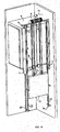
- Fig. 5 is a group view of a lift solution according to the invention, having 1:4 suspension, cage guides on the counterweight side and with two pairs of cage suspension pulleys placed in the lower part of the cage wall on the side where the counterweight stands.
- the split and stagger of the cage suspension pulleys contributes in reducing the cross bulks.
- a particular configuration of such application, illustrated in fig. 7 consists in displacing each pair of the cage suspension pulleys 9 and 19 with rotation planes almost parallel one in respect of the other and the wall plane adjacent to the cage.
- Each pair of pulleys 9 and 19 is placed beside the cage wall and the solution illustrated in fig. 7 shows them overlapped.
- the deflecting pulleys 18 are displaced for the descent of the cage side suspension ropes and the ropes 20 for the descent of the counterweight side ropes.
- the counterweight is provided with two pairs of suspension pulleys 7 to 12.
- the rope path is doubled and there is simply described only one path track, as illustrated in fig. 7 .
- fig. 5 there is pointed out a lift in which the cage 4 supported by a structure 3 slides vertically along the guide 31, connected to a counterweight 5 by an elongated connection element 6 fixed at its ends to connection point 10, at the cage side, and 11, at the counterweight side.
- the counterweight slides vertically along the guides 15.
- the cage suspension and the counterweight suspension are equal to 1:4, with the elongated connection element 6 staring form the cage side connection point 10, falling vertically towards the suspension pulley 19 placed in the lower part of the cage supporting structure, being wrapped around the pulley 19, rising almost vertically towards the deflecting pulley 18 connected to the supporting structure 12 of the machinery, being wrapped around the pulley 18, falling again vertically towards the suspension pulley 9 placed in the lower part of the cage supporting structure, being wrapped around the pulley 9, rising almost vertically towards the traction pulley 8 placed in the upper part of the lift shaft, being wrapped around the same then falling again towards the counterweight suspension pulley 7, being wrapped around the same and restarting upwards along the direction of the deflecting pulley 20 connected to the supporting structure 12 of the machinery, being wrapped around the pulley 20, falling again vertically towards the counterweight suspension pulley 21, being wrapped around the same and returning upwards for being fixed to the support 11 placed on the upper supporting structure 12, which leans on the guides and is fixed to the top of the lift shaft 13.
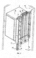
- Fig. 6 is a group view of a solution of the lift according to the invention, having the Rucksack 1:2 suspension, cage guides on the counterweight side and with cage suspension pulleys placed at the bottom of the cage wall on the side where the counterweight stands.
- the splitting of the cage suspension pulleys contributes to reduce the cross bulks.
- Fig. 7 is a group view of a further solution of the lift according to the invention having Rucksack 1:2 suspension, suspension pulleys of the cage and the counterweight such as in the solution of fig. 7 and traction type DW (Double Wrap).
- Fig. 6 shows one of the embodiments of such solution, which provides a size ratio equal to 1:2, in which the cage suspension pulleys are placed at the lower portion of the same, with the rotation plane almost parallel to the adjacent cage wall, a pulley for each rope or rope group coming from each of the traction pulleys.
- the halving of the rope number of each group allows for decreasing the thickness of the cage suspension pulleys, thus reducing the on plan overall dimensions of the spaces not allowable for carrying out the same cage.
- fig 6 is pointed out a lift in which the cage 4 supported by a structure 3 slides vertically along the guides 31, connected to a counterweight 5 by a connection elongated element 6 fixed at its ends to the connection points 10, on the cage side, and 11, on the counterweight side.
- the counterweight slides vertically along the guides 15.
- the suspension of the cage and the counterweight is equal to 1:2, with the connection elongated element 6 starting from the cage side connection point 10, falling down vertically towards the suspension pulley 9 placed in the lower portion of the cage supporting structure, being wrapped around the pulley 9, rising almost vertically towards the traction pulley 8 placed in the top of the lift shaft, being wrapped around the same then falling again downwards the counterweight suspension pulley 7, being wrapped around the same and returning upwards in order to be fixed to the support 11, placed on the upper supporting structure 12, which leans on the guides and is fixed to the top of the lift shaft 13.
- the pulley 8 is part of the lifting machine 14, placed over the top of the lift shaft 13, and supported by the upper supporting structure 12.
- fig. 7 there is shown another version of the lift of the same type illustrated in fig. 6 , in the case in which the friction between the connection elongated element 6 and the traction pulley 8 is not enough to assure the right driving of the cage in all the load conditions.
- the double wrap solution in which to the traction pulley 8 a deflecting pulley 16 is added, placed under the same and slightly shifted towards the cage side or the counterweight.
- the pulley is shifted to the counterweight side, such that the path of the connection elongated element 6 is expanding as disclosed for the case in fig.
- the elongated element 6, once wrapped around the pulley 8, is wrapped around the pulley 16, returns towards the pulley 8, is wrapped around it and passes again onto the pulley 16 from which it moves downwards the counterweight suspension pulley 7.
Applications Claiming Priority (2)
| Application Number | Priority Date | Filing Date | Title |
|---|---|---|---|
| IT002542A ITMI20062542A1 (it) | 2006-12-29 | 2006-12-29 | Ascensore con doppia puleggia di trazione |
| PCT/IB2007/004504 WO2008090413A2 (en) | 2006-12-29 | 2007-12-24 | Lift with dual traction pulley |
Publications (2)
| Publication Number | Publication Date |
|---|---|
| EP2111367A2 EP2111367A2 (en) | 2009-10-28 |
| EP2111367B1 true EP2111367B1 (en) | 2011-06-08 |
Family
ID=39644935
Family Applications (1)
| Application Number | Title | Priority Date | Filing Date |
|---|---|---|---|
| EP07872097A Not-in-force EP2111367B1 (en) | 2006-12-29 | 2007-12-24 | Lift with dual traction pulley |
Country Status (7)
| Country | Link |
|---|---|
| US (1) | US20110042169A1 (it) |
| EP (1) | EP2111367B1 (it) |
| CN (2) | CN103626015A (it) |
| AT (1) | ATE512109T1 (it) |
| ES (1) | ES2380539T3 (it) |
| IT (1) | ITMI20062542A1 (it) |
| WO (1) | WO2008090413A2 (it) |
Families Citing this family (7)
| Publication number | Priority date | Publication date | Assignee | Title |
|---|---|---|---|---|
| US20110272215A1 (en) * | 2008-12-26 | 2011-11-10 | Ernst Ach | Eccentrically suspended elevator car |
| EP2678258B1 (en) * | 2011-02-23 | 2022-05-04 | Otis Elevator Company | Elevator system including a 4:1 roping arrangement |
| CN104773634B (zh) * | 2015-04-09 | 2017-08-15 | 日立电梯(中国)有限公司 | 一种电梯曳引系统 |
| US10053332B2 (en) * | 2016-03-25 | 2018-08-21 | Smart Lifts, Llc | Independent traction drive and suspension systems for a plurality of elevator cabs and counterweights in a hoistway |
| CN109720964A (zh) | 2017-10-27 | 2019-05-07 | 奥的斯电梯公司 | 电梯牵引系统以及电梯系统 |
| KR102092078B1 (ko) * | 2018-09-21 | 2020-03-23 | 전병수 | 엘리베이터용 2:1 로프 체결방식에 적용되는 매달림 시브 |
| CN110668290B (zh) * | 2019-09-18 | 2023-11-14 | 菱王电梯有限公司 | 弓字型电梯承重结构 |
Family Cites Families (19)
| Publication number | Priority date | Publication date | Assignee | Title |
|---|---|---|---|---|
| US4077271A (en) * | 1975-02-19 | 1978-03-07 | Walter M. Mathews | Drive power transmission element |
| US4571225A (en) * | 1984-10-31 | 1986-02-18 | Modern Machine Works Inc. | Sheave assembly |
| CN86205112U (zh) * | 1986-07-21 | 1987-07-22 | 朝阳煤矿 | 一种矿井提升天轮绳衬 |
| FI119237B (fi) * | 2003-01-31 | 2008-09-15 | Kone Corp | Hissi, menetelmä hissin muodostamiseksi ja tasauslaitteiston käyttö |
| DE69810558T2 (de) * | 1997-09-26 | 2003-11-20 | Toshiba Kawasaki Kk | Einsetzen einer Antriebseinheit in einem Aufzugsschacht |
| CN1342130A (zh) * | 1998-02-26 | 2002-03-27 | 奥蒂斯电梯公司 | 采用扁平软性绳索的双滑轮绳索提升器 |
| FI109468B (fi) * | 1998-11-05 | 2002-08-15 | Kone Corp | Vetopyörähissi |
| JP2002167137A (ja) * | 2000-11-29 | 2002-06-11 | Toshiba Corp | エレベータ |
| FI4928U1 (fi) | 2001-01-25 | 2001-05-23 | Kone Corp | Hissi |
| ATE512925T1 (de) * | 2001-11-23 | 2011-07-15 | Inventio Ag | Aufzugssystem |
| US20030121729A1 (en) * | 2002-01-02 | 2003-07-03 | Guenther Heinz | Lift belt and system |
| FI119234B (fi) * | 2002-01-09 | 2008-09-15 | Kone Corp | Hissi |
| JP4270831B2 (ja) * | 2002-09-24 | 2009-06-03 | 東芝エレベータ株式会社 | マシンルームレスエレベータ |
| DE10319731B4 (de) * | 2003-04-30 | 2005-06-02 | Wittur Ag | Aufzug |
| ITMI20031887A1 (it) | 2003-10-02 | 2005-04-03 | L A Consulting S A S Di Sara Faletto & C Sa | Ascensore con fossa e testata ridotta, anche senza locale del macchinario. |
| US7156209B2 (en) * | 2004-05-28 | 2007-01-02 | Inventio Ag | Elevator roping arrangement |
| WO2006005211A1 (de) * | 2004-07-12 | 2006-01-19 | Gaba International Ag | Mundpflegemittel enthaltend chitosanderivat |
| JP5049125B2 (ja) * | 2004-07-12 | 2012-10-17 | インベンテイオ・アクテイエンゲゼルシヤフト | 昇降機および昇降機に使用するためのプーリ組み立て体 |
| CN100400933C (zh) * | 2005-04-21 | 2008-07-09 | 天津港第四港埠公司 | 用于门机臂架的组合式滑轮及其维修安装工艺 |
-
2006
- 2006-12-29 IT IT002542A patent/ITMI20062542A1/it unknown
-
2007
- 2007-12-24 ES ES07872097T patent/ES2380539T3/es active Active
- 2007-12-24 WO PCT/IB2007/004504 patent/WO2008090413A2/en active Application Filing
- 2007-12-24 AT AT07872097T patent/ATE512109T1/de not_active IP Right Cessation
- 2007-12-24 US US12/521,431 patent/US20110042169A1/en not_active Abandoned
- 2007-12-24 EP EP07872097A patent/EP2111367B1/en not_active Not-in-force
- 2007-12-24 CN CN201310627142.6A patent/CN103626015A/zh active Pending
- 2007-12-24 CN CN200780051305.3A patent/CN101626971B/zh not_active Expired - Fee Related
Also Published As
| Publication number | Publication date |
|---|---|
| WO2008090413A3 (en) | 2009-04-23 |
| CN101626971A (zh) | 2010-01-13 |
| ATE512109T1 (de) | 2011-06-15 |
| ITMI20062542A1 (it) | 2008-06-30 |
| CN103626015A (zh) | 2014-03-12 |
| EP2111367A2 (en) | 2009-10-28 |
| WO2008090413A2 (en) | 2008-07-31 |
| CN101626971B (zh) | 2014-01-08 |
| US20110042169A1 (en) | 2011-02-24 |
| ES2380539T3 (es) | 2012-05-16 |
Similar Documents
| Publication | Publication Date | Title |
|---|---|---|
| EP2111367B1 (en) | Lift with dual traction pulley | |
| JP6979883B2 (ja) | 電気リニアモータ | |
| CA2500616C (en) | Lift for large loads | |
| EP1353869B1 (en) | Elevator | |
| JP2005509580A (ja) | エレベータシステム | |
| AU678779B2 (en) | Elevator motor placed in the counterweight | |
| US4807723A (en) | Elevator roping arrangement | |
| EP2576408B1 (en) | Elevator with roller-pinion drive | |
| US8109367B2 (en) | Counterweight and suspension for an elevator without an engine room | |
| EP0639526A2 (en) | Traction type elevator | |
| JP2008156116A (ja) | 昇降路内で相互に上下に配置された2台のエレベータケージを有するエレベータ | |
| EP2776355B1 (en) | Elevator system | |
| JP2008115015A (ja) | 昇降路内に2つのエレベータケージを互いに上下に配置して備えるエレベータ | |
| EP2521684B1 (en) | Elevator system with one pair of guide rails | |
| WO2012115632A1 (en) | Elevator system including a 4:1 roping arrangement | |
| US20110315487A1 (en) | Arrangement of elevator machines | |
| US20110042170A1 (en) | Lift with balancing weight | |
| US10023436B2 (en) | Drive with multiple looping for an elevator installation | |
| IES20060641A2 (en) | Hoisting system and elevator without a machine room | |
| EP3274285B1 (en) | Elevator system suspension member termination | |
| EP1125883A1 (en) | Machine and support assembly for elevators | |
| EP3747815A1 (en) | Elevator | |
| EP1727761B1 (en) | Elevator | |
| IES84548Y1 (en) | Hoisting system and elevator without a machine room |
Legal Events
| Date | Code | Title | Description |
|---|---|---|---|
| PUAI | Public reference made under article 153(3) epc to a published international application that has entered the european phase |
Free format text: ORIGINAL CODE: 0009012 |
|
| 17P | Request for examination filed |
Effective date: 20090728 |
|
| AK | Designated contracting states |
Kind code of ref document: A2 Designated state(s): AT BE BG CH CY CZ DE DK EE ES FI FR GB GR HU IE IS IT LI LT LU LV MC MT NL PL PT RO SE SI SK TR |
|
| 17Q | First examination report despatched |
Effective date: 20091112 |
|
| DAX | Request for extension of the european patent (deleted) | ||
| GRAP | Despatch of communication of intention to grant a patent |
Free format text: ORIGINAL CODE: EPIDOSNIGR1 |
|
| GRAS | Grant fee paid |
Free format text: ORIGINAL CODE: EPIDOSNIGR3 |
|
| GRAA | (expected) grant |
Free format text: ORIGINAL CODE: 0009210 |
|
| AK | Designated contracting states |
Kind code of ref document: B1 Designated state(s): AT BE BG CH CY CZ DE DK EE ES FI FR GB GR HU IE IS IT LI LT LU LV MC MT NL PL PT RO SE SI SK TR |
|
| REG | Reference to a national code |
Ref country code: GB Ref legal event code: FG4D |
|
| REG | Reference to a national code |
Ref country code: CH Ref legal event code: EP |
|
| REG | Reference to a national code |
Ref country code: IE Ref legal event code: FG4D |
|
| REG | Reference to a national code |
Ref country code: DE Ref legal event code: R096 Ref document number: 602007015141 Country of ref document: DE Effective date: 20110721 |
|
| REG | Reference to a national code |
Ref country code: NL Ref legal event code: VDEP Effective date: 20110608 |
|
| PG25 | Lapsed in a contracting state [announced via postgrant information from national office to epo] |
Ref country code: SE Free format text: LAPSE BECAUSE OF FAILURE TO SUBMIT A TRANSLATION OF THE DESCRIPTION OR TO PAY THE FEE WITHIN THE PRESCRIBED TIME-LIMIT Effective date: 20110608 Ref country code: LT Free format text: LAPSE BECAUSE OF FAILURE TO SUBMIT A TRANSLATION OF THE DESCRIPTION OR TO PAY THE FEE WITHIN THE PRESCRIBED TIME-LIMIT Effective date: 20110608 |
|
| REG | Reference to a national code |
Ref country code: GR Ref legal event code: EP Ref document number: 20110402128 Country of ref document: GR Effective date: 20111013 |
|
| PG25 | Lapsed in a contracting state [announced via postgrant information from national office to epo] |
Ref country code: AT Free format text: LAPSE BECAUSE OF FAILURE TO SUBMIT A TRANSLATION OF THE DESCRIPTION OR TO PAY THE FEE WITHIN THE PRESCRIBED TIME-LIMIT Effective date: 20110608 Ref country code: FI Free format text: LAPSE BECAUSE OF FAILURE TO SUBMIT A TRANSLATION OF THE DESCRIPTION OR TO PAY THE FEE WITHIN THE PRESCRIBED TIME-LIMIT Effective date: 20110608 Ref country code: SI Free format text: LAPSE BECAUSE OF FAILURE TO SUBMIT A TRANSLATION OF THE DESCRIPTION OR TO PAY THE FEE WITHIN THE PRESCRIBED TIME-LIMIT Effective date: 20110608 Ref country code: LV Free format text: LAPSE BECAUSE OF FAILURE TO SUBMIT A TRANSLATION OF THE DESCRIPTION OR TO PAY THE FEE WITHIN THE PRESCRIBED TIME-LIMIT Effective date: 20110608 Ref country code: CY Free format text: LAPSE BECAUSE OF FAILURE TO SUBMIT A TRANSLATION OF THE DESCRIPTION OR TO PAY THE FEE WITHIN THE PRESCRIBED TIME-LIMIT Effective date: 20110608 |
|
| PG25 | Lapsed in a contracting state [announced via postgrant information from national office to epo] |
Ref country code: BE Free format text: LAPSE BECAUSE OF FAILURE TO SUBMIT A TRANSLATION OF THE DESCRIPTION OR TO PAY THE FEE WITHIN THE PRESCRIBED TIME-LIMIT Effective date: 20110608 Ref country code: NL Free format text: LAPSE BECAUSE OF FAILURE TO SUBMIT A TRANSLATION OF THE DESCRIPTION OR TO PAY THE FEE WITHIN THE PRESCRIBED TIME-LIMIT Effective date: 20110608 |
|
| PG25 | Lapsed in a contracting state [announced via postgrant information from national office to epo] |
Ref country code: PT Free format text: LAPSE BECAUSE OF FAILURE TO SUBMIT A TRANSLATION OF THE DESCRIPTION OR TO PAY THE FEE WITHIN THE PRESCRIBED TIME-LIMIT Effective date: 20111010 Ref country code: EE Free format text: LAPSE BECAUSE OF FAILURE TO SUBMIT A TRANSLATION OF THE DESCRIPTION OR TO PAY THE FEE WITHIN THE PRESCRIBED TIME-LIMIT Effective date: 20110608 Ref country code: CZ Free format text: LAPSE BECAUSE OF FAILURE TO SUBMIT A TRANSLATION OF THE DESCRIPTION OR TO PAY THE FEE WITHIN THE PRESCRIBED TIME-LIMIT Effective date: 20110608 Ref country code: IS Free format text: LAPSE BECAUSE OF FAILURE TO SUBMIT A TRANSLATION OF THE DESCRIPTION OR TO PAY THE FEE WITHIN THE PRESCRIBED TIME-LIMIT Effective date: 20111008 |
|
| PG25 | Lapsed in a contracting state [announced via postgrant information from national office to epo] |
Ref country code: PL Free format text: LAPSE BECAUSE OF FAILURE TO SUBMIT A TRANSLATION OF THE DESCRIPTION OR TO PAY THE FEE WITHIN THE PRESCRIBED TIME-LIMIT Effective date: 20110608 Ref country code: RO Free format text: LAPSE BECAUSE OF FAILURE TO SUBMIT A TRANSLATION OF THE DESCRIPTION OR TO PAY THE FEE WITHIN THE PRESCRIBED TIME-LIMIT Effective date: 20110608 Ref country code: SK Free format text: LAPSE BECAUSE OF FAILURE TO SUBMIT A TRANSLATION OF THE DESCRIPTION OR TO PAY THE FEE WITHIN THE PRESCRIBED TIME-LIMIT Effective date: 20110608 |
|
| PLBE | No opposition filed within time limit |
Free format text: ORIGINAL CODE: 0009261 |
|
| STAA | Information on the status of an ep patent application or granted ep patent |
Free format text: STATUS: NO OPPOSITION FILED WITHIN TIME LIMIT |
|
| 26N | No opposition filed |
Effective date: 20120309 |
|
| REG | Reference to a national code |
Ref country code: ES Ref legal event code: FG2A Ref document number: 2380539 Country of ref document: ES Kind code of ref document: T3 Effective date: 20120516 |
|
| PG25 | Lapsed in a contracting state [announced via postgrant information from national office to epo] |
Ref country code: DK Free format text: LAPSE BECAUSE OF FAILURE TO SUBMIT A TRANSLATION OF THE DESCRIPTION OR TO PAY THE FEE WITHIN THE PRESCRIBED TIME-LIMIT Effective date: 20110608 |
|
| REG | Reference to a national code |
Ref country code: DE Ref legal event code: R097 Ref document number: 602007015141 Country of ref document: DE Effective date: 20120309 |
|
| PG25 | Lapsed in a contracting state [announced via postgrant information from national office to epo] |
Ref country code: MC Free format text: LAPSE BECAUSE OF NON-PAYMENT OF DUE FEES Effective date: 20111231 |
|
| REG | Reference to a national code |
Ref country code: CH Ref legal event code: PL |
|
| REG | Reference to a national code |
Ref country code: IE Ref legal event code: MM4A |
|
| PG25 | Lapsed in a contracting state [announced via postgrant information from national office to epo] |
Ref country code: LI Free format text: LAPSE BECAUSE OF NON-PAYMENT OF DUE FEES Effective date: 20111231 Ref country code: CH Free format text: LAPSE BECAUSE OF NON-PAYMENT OF DUE FEES Effective date: 20111231 Ref country code: IE Free format text: LAPSE BECAUSE OF NON-PAYMENT OF DUE FEES Effective date: 20111224 |
|
| PG25 | Lapsed in a contracting state [announced via postgrant information from national office to epo] |
Ref country code: MT Free format text: LAPSE BECAUSE OF FAILURE TO SUBMIT A TRANSLATION OF THE DESCRIPTION OR TO PAY THE FEE WITHIN THE PRESCRIBED TIME-LIMIT Effective date: 20110608 |
|
| PG25 | Lapsed in a contracting state [announced via postgrant information from national office to epo] |
Ref country code: LU Free format text: LAPSE BECAUSE OF NON-PAYMENT OF DUE FEES Effective date: 20111224 |
|
| PG25 | Lapsed in a contracting state [announced via postgrant information from national office to epo] |
Ref country code: BG Free format text: LAPSE BECAUSE OF FAILURE TO SUBMIT A TRANSLATION OF THE DESCRIPTION OR TO PAY THE FEE WITHIN THE PRESCRIBED TIME-LIMIT Effective date: 20110908 |
|
| PG25 | Lapsed in a contracting state [announced via postgrant information from national office to epo] |
Ref country code: HU Free format text: LAPSE BECAUSE OF FAILURE TO SUBMIT A TRANSLATION OF THE DESCRIPTION OR TO PAY THE FEE WITHIN THE PRESCRIBED TIME-LIMIT Effective date: 20110608 |
|
| PGFP | Annual fee paid to national office [announced via postgrant information from national office to epo] |
Ref country code: DE Payment date: 20131217 Year of fee payment: 7 Ref country code: GB Payment date: 20131219 Year of fee payment: 7 |
|
| PGFP | Annual fee paid to national office [announced via postgrant information from national office to epo] |
Ref country code: IT Payment date: 20131216 Year of fee payment: 7 Ref country code: ES Payment date: 20131204 Year of fee payment: 7 Ref country code: TR Payment date: 20131216 Year of fee payment: 7 Ref country code: GR Payment date: 20131213 Year of fee payment: 7 |
|
| PGFP | Annual fee paid to national office [announced via postgrant information from national office to epo] |
Ref country code: FR Payment date: 20131227 Year of fee payment: 7 |
|
| REG | Reference to a national code |
Ref country code: DE Ref legal event code: R119 Ref document number: 602007015141 Country of ref document: DE |
|
| GBPC | Gb: european patent ceased through non-payment of renewal fee |
Effective date: 20141224 |
|
| REG | Reference to a national code |
Ref country code: GR Ref legal event code: ML Ref document number: 20110402128 Country of ref document: GR Effective date: 20150722 |
|
| REG | Reference to a national code |
Ref country code: FR Ref legal event code: ST Effective date: 20150831 |
|
| PG25 | Lapsed in a contracting state [announced via postgrant information from national office to epo] |
Ref country code: DE Free format text: LAPSE BECAUSE OF NON-PAYMENT OF DUE FEES Effective date: 20150701 Ref country code: GB Free format text: LAPSE BECAUSE OF NON-PAYMENT OF DUE FEES Effective date: 20141224 |
|
| PG25 | Lapsed in a contracting state [announced via postgrant information from national office to epo] |
Ref country code: FR Free format text: LAPSE BECAUSE OF NON-PAYMENT OF DUE FEES Effective date: 20141231 Ref country code: GR Free format text: LAPSE BECAUSE OF NON-PAYMENT OF DUE FEES Effective date: 20150722 |
|
| PG25 | Lapsed in a contracting state [announced via postgrant information from national office to epo] |
Ref country code: IT Free format text: LAPSE BECAUSE OF NON-PAYMENT OF DUE FEES Effective date: 20141224 |
|
| REG | Reference to a national code |
Ref country code: ES Ref legal event code: FD2A Effective date: 20160127 |
|
| PG25 | Lapsed in a contracting state [announced via postgrant information from national office to epo] |
Ref country code: ES Free format text: LAPSE BECAUSE OF NON-PAYMENT OF DUE FEES Effective date: 20141225 |
|
| PG25 | Lapsed in a contracting state [announced via postgrant information from national office to epo] |
Ref country code: TR Free format text: LAPSE BECAUSE OF NON-PAYMENT OF DUE FEES Effective date: 20141224 |