EP2111367B1 - Lift with dual traction pulley - Google Patents
Lift with dual traction pulley Download PDFInfo
- Publication number
- EP2111367B1 EP2111367B1 EP07872097A EP07872097A EP2111367B1 EP 2111367 B1 EP2111367 B1 EP 2111367B1 EP 07872097 A EP07872097 A EP 07872097A EP 07872097 A EP07872097 A EP 07872097A EP 2111367 B1 EP2111367 B1 EP 2111367B1
- Authority
- EP
- European Patent Office
- Prior art keywords
- suspension
- cage
- pulley
- counterweight
- lift
- Prior art date
- Legal status (The legal status is an assumption and is not a legal conclusion. Google has not performed a legal analysis and makes no representation as to the accuracy of the status listed.)
- Not-in-force
Links
Images


Classifications
-
- B—PERFORMING OPERATIONS; TRANSPORTING
- B66—HOISTING; LIFTING; HAULING
- B66B—ELEVATORS; ESCALATORS OR MOVING WALKWAYS
- B66B15/00—Main component parts of mining-hoist winding devices
- B66B15/02—Rope or cable carriers
- B66B15/04—Friction sheaves; "Koepe" pulleys
-
- B—PERFORMING OPERATIONS; TRANSPORTING
- B66—HOISTING; LIFTING; HAULING
- B66B—ELEVATORS; ESCALATORS OR MOVING WALKWAYS
- B66B11/00—Main component parts of lifts in, or associated with, buildings or other structures
- B66B11/0065—Roping
- B66B11/008—Roping with hoisting rope or cable operated by frictional engagement with a winding drum or sheave
Landscapes
- Engineering & Computer Science (AREA)
- Civil Engineering (AREA)
- Mechanical Engineering (AREA)
- Structural Engineering (AREA)
- Lift-Guide Devices, And Elevator Ropes And Cables (AREA)
- Cage And Drive Apparatuses For Elevators (AREA)
- Harvesting Machines For Root Crops (AREA)
- Devices For Conveying Motion By Means Of Endless Flexible Members (AREA)
Abstract
Description
- The present invention relates to systems for maximizing the cage size in lift plants by a traction machine provided with two traction pulleys, each having about half size in respect of a common pulley, on which the suspension ropes are wrapped divided into two groups, each of these realizes a ratio suspension equal to 1:4 or greater, either for the cage or the counterweight.
- Nowadays the elimination of the machine room for lifts is a common practice, so much that even an European standard has been published, the EN 81-1 A3, for the safety requirements of such MRL lifts.
- A problem still to be appropriately solved, in order to make cheaper and more effective the manufacture of lifts, especially MRL lifts, consists in compacting to the maximum all the auxiliary apparatuses to be installed in the lift shaft. That is in order to maximize the cage size, in a lift shaft small in size, for allowing a grater usable capacity, especially when preexistent plants have to be renewed with a lift shaft not modifiable in width and for allowing a better accessibility even for handicapped users. In order to obtain that result different elements can specifically modified, especially those having on plan a bulk in the lift shaft. This problem is faced for a long time and several solutions have just been supposed, which actually present many contraindications.
- A known method to reduce the number of the ropes wrapped around the pulleys and so the thickness of the same pulleys consists in increasing the size ratio of the lift suspension, this allowing to halve the rope number or even to reduce it further. The increasing of the size ratio, by the decreasing of rope number, has the further advantage, as well as reducing the thickness of the pulleys, around which the ropes are wrapped, particularly the traction pulley, of reducing also the size of the driving machine. This, in many situations, allows a great reduction of the bulk being to advantage of the cage size increasing. The size increasing leads, under the same power, to a speed increasing, due to less torque on each pulley.
- Herein the size ratio is defined by a notation referring to ratio between the speed of the mass to be moved and the speed of the suspension elongated element, therefore 1:4, 1:6, etc.
- In other documents other notations can be adopted, defining instead ratio between the weight of the mass to be moved and the traction load on the suspension element, therefore 4:1, 6:1, etc.
- In the following disclosure flat belts, grooved belts, circular section ropes will be indifferently mentioned, such as possible examples of suspension elongated elements. An expedient useful to make the lift building cheaper and more efficient consists in compacting to the maximum all the auxiliary apparatuses to be installed in the lift shaft, even though lifts without machine room are built, in order to maximize the cage size, in a lift shaft limited in size, allowing all the users a better accessibility.
- In order to obtain such a result different elements can be specifically modified which, on plan, are really considerable bulks in the lift shaft, bulks such that they limit the maximum size achievable for the cage. The modifications in these terms cannot leave outside the consideration the fact that in a lift there are parts having bulky dimensions pretty considerable and therefore requiring minimum spaces, between the cage and the lift shaft walls, to be realized in which other essential parts can be housed, such that free spaces are optimized and the overall dimensions of the lift shaft under the same cage size are reduced.
- The first operation consists in trying to reduce the size of the basic parts, in order to minimize the dimensions of free spaces not completely used. There have been provided solutions which allow, increasing the size ratio for the cage lifting, for using a lower number of ropes and therefore suspension and deflecting pulleys with a contained thickness, as well as driving motors with even more reduced driving torque thus smaller in size. By the inventive solution hereinafter disclosed the free space use existing in the lift shaft are intended to be optimized, by the use of doubled parts having dimensions reduced in respect of the parts necessary into similar solutions without doubled parts.
- It is particularly provided to build a lift without the machine room, in which a traction machine is adopted provided with two traction pulleys, each having almost half size in respect of the common pulley and diameter even smaller than 300 mm, on which the suspension ropes are wrapped divided into two groups, each of these realize a suspension ratio equal to 1:2 or greater, either for the cage or the counterweight. The thickness dimensions of the suspension and deflecting pulleys are almost half in respect of the pulleys necessary for a similar conventional ratio suspension. Therefore in the lift shaft the crossing bulk dimensions of the apparatuses, used according to the innovative proposal disclosed, are more contained and allow advantageously for realizing, under the same lift shaft size, a cage bigger in size. Alternatively, under the same cage dimensions, smaller dimensions of the lift shaft are enough to contain advantageously all the lift apparatuses.
- The doubling of the cage suspension pulleys allows a better load distribution and therefore a mass reduction of the cage, and then it is also possible to reduce the mass and size of the counterweight, in favour of the possible dimensions of the cage, under the same lift shaft. This implies the need to increase friction between ropes and pulleys. This further problem can be solved by adopting a double wrap roping or similar solutions.
- Document
EP 0 905 081 A , which concerns direct suspended (1:1) lifts fitted with a traction machine having two separated traction sheaves placed at the extremities of the machine shaft, shows how to reduce the thickness of each traction sheave, although it does not give any indication on how to reduce the overall dimensions of the traction sheave, including its diameter. The whole document is actually focused on proposing 1.1 suspension solutions that, in some cases, could enable a more centric suspension of the car by running and fixing the car suspension ropes on two possibly opposite sides of the car itself. The reduction of the dimensions of the machine and of the traction sheaves is not a concern and this brings to the inconvenience that they are not fully contained between a side wall of the car and the wall of the lift shaft on the corresponding side, so much so that some solutions even require chamfering the corners of the car for permitting the positioning of the suspension ropes and the relevant fixings to the car. This document does not provide any indications concerning the realization of suspension ratios different from 1:1 and therefore also on how to optimize the empty spaces in the well by reducing the thickness of the deviation pulleys placed in the lift shaft, which are never taken into account or mentioned. - Another existing document,
WO02059028 A - So document
W002059028 A - Also document
EP 1520831 A1 seems to be anticipating a lift solution with a Rucksack type of car and counterweight guiding system, where the suspension of the car cage is obtained by means of two or more separate independent pulleys. This solution concerns Rucksack type lift applications in which the machine has a single traction sheave which has the rotation plane parallel to the car wall adjacent to the car and counterweight guiding system. The proposed doubling of the car suspension system is achieved by passing all the suspension ropes over one diverting pulley and only half of the suspension ropes over one additional separate diverting pulley on top of the lift well, both diverting pulleys having a rotation plane also parallel to the car wall adjacent to the car and counterweight guiding system. This prior art does not appear to be consistent with any possibility of placing in the same top of the lift well a traction machine with double traction sheave, with the rotation planes perpendicular to the car wall adjacent to the car and counterweight guiding system and achieving, at the same time, a reduction of the space taken by the machine, the traction sheave and the diverting pulleys. - The features of the present inventive solution disclosed at the beginning of this document can be found in the following description, in some of the possible advantageous configurations. Embodiments not limiting of the present invention are shown in the annexed drawings. In detail:
-
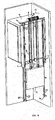
Fig. 1 is a top front lateral perspective view of a version of the lift object of the invention with suspension ratio equal to 1:4. -
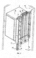
Fig. 2 is a rear lateral perspective view of the lift shown infig. 1 . -
Fig 3 is a group perspective view of another version of the lift according to the invention in an embodiment with suspension equal to 1:4 and cage suspension pulleys placed on the roof of the same. This solution allows for obtaining a very reduced hollow depth. -
Fig. 4 is a perspective view of an embodiment of the race dowelling of the pulley and the shape of the housing groove not forming part of the invention as claimed. -
Fig. 5 is a group view of a solution for the lift according to the invention having suspension equal to 1:4. -
Fig. 6 is a group view of a solution for the lift according to the invention having Rucksack suspension equal to 1:2. -
Fig. 7 is a group view of a further solution for the lift according to the invention having Rucksack suspension equal to 1:2. - The path of the ropes showed as follows, is described as illustrative and not limiting and refers to one of the multiple solutions achievable using the object of the invention.
- With reference to
fig. 1 and2 , there is described an invention relating to a lift with suspension equal to 1:4, without machine room, called MRL (Machine Room Less), in which thecounterweight 5 runs along theguides 35, beside the cage 4, running along the guides 36. In the shown solution the motor 3 placed on the top of the vertical of thecounterweight 5 and supported by a supporting crossbar 6, is provided with two pulleys. 1 and 2 placed on the two opposite sides of the drive shaft opposite in respect of the framework of the same motor, placed towards the counterweight side. The ropes are divided into two groups each having at least one rope. In the description we refer to only one rope for each group,rope 33 andrope 34, in which any additional rope of each group runs along a similar path. Therope 33 has one of the ends fixed to theconnection 19 placed onto the supporting crossbar 7 within the lift hollow upright the counterweight. The rope path is described as follows, and due to the symmetry of the problem only the path of therope 33 will be described. Starting from theconnection 19, therope 33 goes down towards thecounterweight 5, where it is wrapped around thecounterweight suspension pulley 18, then returning upwards, where it crosses a deflectingpulley 17 which sends it back to a counterweight suspension pulley 16, around which it is wrapped before returning upwards thus crossing the traction pulley 1 of the machine 3, on its pertaining side. Therope 33 then passes under the cage and over the pair of suspension pulleys 11 and 12 (pulley 12 symmetric in respect of the pulley 11 and not shown in figure), then being wrapped around the deflectingpulley 13 placed on the top beside the cage guide 36, on the side opposite to the counterweight. The deflectingpulley 13 is at least in part contained by the bulk given by cage guide, placed between the cage wall and the adjacent lift shaft wall. From the deflectingpulley 13 therope 33 returns downwards to the cage bottom and passes again under the same, through another pair of suspension pulleys 14 and 15 (pulley 14 symmetric in respect of thepulley 15 and not shown in figure), thus going upwards and having the end fixed to theupper connection 10 onto the crossbar 7. The path of therope 34 is similar and symmetric in respect of what seen about therope 33. On the counterweight side thecounterweight suspension pulleys 16 and 18 and the deflecting 17 have the rotation plan inclined in respect of the adjacent walls of the cage and the lift shaft, so as to reduce the cross bulk and distributing the ratio pulleys along the width of the counterweight. Similarly for the corresponding pulleys involved in the path of therope 34. The advantage of such solution, for which it is provided that traction pulleys with races provided with removable improved friction covering dowels may be used, is to reduce cross bulks of the ratio pulleys and ropes, by the expedient of dividing the ropes into two groups. Such expedient allows also for placing the cageside deflecting pulleys - Referring now to
fig. 4 there is shown an embodiment not forming part of the invention as claimed, said embodiment comprising adowelling arc 301 of amulti-race pulley 305, of which herein only a race is illustrated, sectioned and with thedowelling arc 301 inserted in thecircular race 307 with undercut 306. The same dowelling further provides a section withside wings 302, aim of which is to provide a protection and lateral guide for the rope. The possibility to manufacture the pulley dowelling by dowellingarcs 301 separable one from another allows an easier replacement by segments, by rotating the pulley on which they are mounted around an arc suitable for the replacement, without disassembling the ropes in order to replace the whole circular dowel. This represents an important advantage in terms of comfort and cost, considering the stop time and therefore the dowelling maintenance. In order to allow an easy replacement of the dowels, they must be at least three for each pulley race. Once worn by friction the filleted bottom of the dowel where preferably the rope abuts, this comes in contact with the race metallic surface, but in part rests abutted onto the dowel tang inserted in the undercut 306, which assures enough friction for moving during short periods, because of the excessive consumption of the ropes under these conditions. - Even referring to
fig. 4 , the function of the undercut 306 either to provide a mounting system and holding in place for the dowelling arcs 301, or, in case of their wear, to assure a certain friction between the undercut 306 and the metallic ropes so as to allow for moving the lift during a short period, though not assuring a rope life comparable to the one in presence of dowelling, due to their wear when in contact with the undercut 306. - Other innovative solutions based on the two separate traction pulley machine are hereinafter illustrated and they refer to a lift with suspension commonly called Rucksack, in which the cage guides are placed on only one side of the cage, side on which the counterweight is also housed. Another embodiment of the innovative solution illustrated provides again the use of a cage 4 with a Rucksack suspension and size ratio equal to 1:4, in which the cage suspension pulleys are placed in the lower part of the same, at each descent of the ropes coming from the two traction pulleys.
-
Fig. 5 is a group view of a lift solution according to the invention, having 1:4 suspension, cage guides on the counterweight side and with two pairs of cage suspension pulleys placed in the lower part of the cage wall on the side where the counterweight stands. The split and stagger of the cage suspension pulleys contributes in reducing the cross bulks. A particular configuration of such application, illustrated infig. 7 , consists in displacing each pair of the cage suspension pulleys 9 and 19 with rotation planes almost parallel one in respect of the other and the wall plane adjacent to the cage. Each pair ofpulleys fig. 7 shows them overlapped. At theupper crossbars 12 supporting the machinery, placed on the top of the lift shaft, outside the cage projection, the deflecting pulleys 18 are displaced for the descent of the cage side suspension ropes and theropes 20 for the descent of the counterweight side ropes. The counterweight is provided with two pairs of suspension pulleys 7 to 12. The rope path is doubled and there is simply described only one path track, as illustrated infig. 7 . Infig. 5 there is pointed out a lift in which the cage 4 supported by a structure 3 slides vertically along theguide 31, connected to acounterweight 5 by an elongated connection element 6 fixed at its ends toconnection point 10, at the cage side, and 11, at the counterweight side. The counterweight slides vertically along theguides 15. The cage suspension and the counterweight suspension are equal to 1:4, with the elongated connection element 6 staring form the cageside connection point 10, falling vertically towards thesuspension pulley 19 placed in the lower part of the cage supporting structure, being wrapped around thepulley 19, rising almost vertically towards the deflectingpulley 18 connected to the supportingstructure 12 of the machinery, being wrapped around thepulley 18, falling again vertically towards thesuspension pulley 9 placed in the lower part of the cage supporting structure, being wrapped around thepulley 9, rising almost vertically towards thetraction pulley 8 placed in the upper part of the lift shaft, being wrapped around the same then falling again towards the counterweight suspension pulley 7, being wrapped around the same and restarting upwards along the direction of the deflectingpulley 20 connected to the supportingstructure 12 of the machinery, being wrapped around thepulley 20, falling again vertically towards thecounterweight suspension pulley 21, being wrapped around the same and returning upwards for being fixed to the support 11 placed on the upper supportingstructure 12, which leans on the guides and is fixed to the top of thelift shaft 13. Thepulley 8 is a part of the lifting machine 14, placed over the top of thelift shaft 13, and supported by the upper supportingstructure 12. -
Fig. 6 is a group view of a solution of the lift according to the invention, having the Rucksack 1:2 suspension, cage guides on the counterweight side and with cage suspension pulleys placed at the bottom of the cage wall on the side where the counterweight stands. The splitting of the cage suspension pulleys contributes to reduce the cross bulks. -
Fig. 7 is a group view of a further solution of the lift according to the invention having Rucksack 1:2 suspension, suspension pulleys of the cage and the counterweight such as in the solution offig. 7 and traction type DW (Double Wrap).Fig. 6 shows one of the embodiments of such solution, which provides a size ratio equal to 1:2, in which the cage suspension pulleys are placed at the lower portion of the same, with the rotation plane almost parallel to the adjacent cage wall, a pulley for each rope or rope group coming from each of the traction pulleys. The halving of the rope number of each group allows for decreasing the thickness of the cage suspension pulleys, thus reducing the on plan overall dimensions of the spaces not allowable for carrying out the same cage. Infig 6 is pointed out a lift in which the cage 4 supported by a structure 3 slides vertically along theguides 31, connected to acounterweight 5 by a connection elongated element 6 fixed at its ends to the connection points 10, on the cage side, and 11, on the counterweight side. The counterweight slides vertically along theguides 15. The suspension of the cage and the counterweight is equal to 1:2, with the connection elongated element 6 starting from the cageside connection point 10, falling down vertically towards thesuspension pulley 9 placed in the lower portion of the cage supporting structure, being wrapped around thepulley 9, rising almost vertically towards thetraction pulley 8 placed in the top of the lift shaft, being wrapped around the same then falling again downwards the counterweight suspension pulley 7, being wrapped around the same and returning upwards in order to be fixed to the support 11, placed on the upper supportingstructure 12, which leans on the guides and is fixed to the top of thelift shaft 13. Thepulley 8 is part of the lifting machine 14, placed over the top of thelift shaft 13, and supported by the upper supportingstructure 12. - In
fig. 7 there is shown another version of the lift of the same type illustrated infig. 6 , in the case in which the friction between the connection elongated element 6 and thetraction pulley 8 is not enough to assure the right driving of the cage in all the load conditions. In such case can be adopted, indeed, advantageously the double wrap solution (DW), in which to the traction pulley 8 a deflecting pulley 16 is added, placed under the same and slightly shifted towards the cage side or the counterweight. In the case shown infig. 6 the pulley is shifted to the counterweight side, such that the path of the connection elongated element 6 is expanding as disclosed for the case infig. 7 , except the track between thepulley 8, pulley 7 and the connection point 11, which is modified as follows: the elongated element 6, once wrapped around thepulley 8, is wrapped around the pulley 16, returns towards thepulley 8, is wrapped around it and passes again onto the pulley 16 from which it moves downwards the counterweight suspension pulley 7. The suspension elongated element, once wrapped around the pulley 7 rising almost vertically in order to be fixed to thesupport 12, in the connection point 11. The lift object of the invention can advantageously present other features object of further embodiments. These are herein schematically listed as exemplificative and not limiting: - cage suspension ratio equal to 1:5
- cage suspension ratio equal to 1:6
- as mentioned, the cage suspension elongated element can be ropes, flat belts or grooved belt
- the position of the cage suspension pulleys can be over the cage top, rather than under the bottom
- the cage suspension pulleys with 1:4 Rucksack archway can be placed with rotation planes parallel or inclined or perpendicular one in respect of the other
- the two traction pulleys for lifts with Rucksack archway can be brought nearer one to the other and placed at the central portion of the lifting machine
- the guide of the cage and counterweight of the lift with Rucksack archway can be displaced on the same side if the connection elements to the
- structure of the lift shaft
- the counterweight suspension of the lifts with Rucksack archway can be made by one or more pulleys having the rotation plane parallel to the guide plane, or inclined or perpendicular in respect of the guide plane.
Claims (13)
- A lift without machine room (MRL, Machine Room Less) suitable for buildings, which comprises a traction machine placed inside the lift shaft with double traction pulley having the rotation plane perpendicular (or the rotation axis parallel) to the car cage wall plane delimiting the volume in which the traction machine is placed , characterized by the fact that the traction pulleys are small in size, with a first traction pulley (1) and a second traction pulley (2) placed in the space between the cage wall and the adjacent wall of the lift shaft and with a configuration of suspension pulleys and elongated suspension elements in the lift shaft so as to obtain a suspension of the cage (4) and a counterweight (5) at least 1:4 in ratio.
- The lift according to claim 1 wherein the suspension pulleys of the counterweight (5) and the deflecting pulleys next to the motor have a rotation plane inclined in respect of the adjacent walls of the cage (4) and of the lift shaft, so as to reduce the cross bulks and to split the ratio size pulleys along the counterweight width, and they are placed in the space between the cage wall and the adjacent wall of the lift shaft.
- The lift according to claim 1 or 2 wherein the suspension ratio is 1:5.
- The lift according to claim 1 or 2 wherein the suspension ratio is 1:6.
- The lift according to one of the preceding claims wherein the suspension pulleys of the cage (4) are placed on the top of the cage (4).
- The lift according to anyone of the preceding claims 1 to 5 wherein the suspension elongated elements are ropes.
- The lift according to anyone of the preceding claims 1 to 5 wherein the suspension elongated elements are flat belts.
- The lift according to anyone of the preceding claims 1 to 5 wherein the suspension elongated elements are grooved belts.
- The lift according to one of the claims 1 or 6 to 8, when not combined with 3 and 4, comprising the counterweight (5) on the side of the cage (4), in which a motor (3), placed at the top upright the counterweight (5) and supported by a supporting crossbar (6), is provided with the first traction pulley (1) and the second traction pulley (2) placed on two opposite sides of the driving shaft (3) parallel to the adjacent wall of the car cage (4); and wherein the suspension elongated elements are divided into two groups each having at least one suspension elongated element, a group for the pulley (1) and a group for the pulley (2), with one suspension elongated element (33) of the first group and one suspension elongated element (34) of the second group; the suspension elongated element (33) having one of the ends fixed to a joint (19), placed on a supporting crossbar (7) placed at the top, into the lift shaft, over the counterweight (5); starting from the joint (19) the suspension elongated element (33), going down towards the counterweight (5), where it is wrapped around a counterweight suspension pulley (18), then returning upwards, where it crosses a deflecting pulley (17) placed next to the supporting crossbar (6) which resends to a suspension pulley (16) of the counterweight (5), around which it is wrapped in order to return upwards and to cross the traction pulley (1) of the motor (3); the suspension elongated element (33) then passes on the pair of suspension pulleys (11) e (12) placed under the cage the pulley (12) symmetric to the (11) in respect of the cage entry door; the suspension elongated element (33) is then wrapped around the deflecting pulley (13) placed at the top beside a cage guide (36), on the opposite side of the counterweight (5), in the space between the cage wall and the lift shaft wall; from the deflecting pulley (13) the suspension elongated element (33) returns towards the cage bottom and passes again under the same, through a second pair of suspension pulleys (14) and (15) placed under the cage (4), the (14) symmetric to the (15) in respect of the cage entry door, then going upwards and having the end fixed on an upper joint (10) on the crossbar (7); for the suspension elongated element (34) the path is similar and symmetric in respect of what seen about the suspension elongated element (33).
- A lift without machine room (MRL, Machine Room Less) suitable for buildings with Rucksack cage suspension, cage guide displacement on the same side of the counterweight, a traction machine, placed at the top inside the lift shaft, with a double traction pulley small in size, with a first traction pulley (1) and a second traction pulley (2) placed in the space between the cage wall and the adjacent wall of the lift shaft and characterized by the fact that it has a configuration of the suspension pulleys and suspension elongated element in the lift shaft so as to obtain two groups of suspension elements of a cage (4) and a counterweight (5) at least 1:4 in size ratio.
- The lift according to claim 11 characterized by the fact that the suspension pulleys of the cage (4) are placed at the lower portion of the cage, in the space between the cage wall and the adjacent counterweight wall, and have a rotation plane placed so as to distribute the size ratio pulleys along the width of the cage and to reduce the cross bulks.
- The lift according to claims 10 and 11 characterized by the fact t that the suspension pulleys of the counterweight (5) and the deflecting pulleys next to the motor are contained in the space between the cage wall and the adjacent wall of the lift shaft and are displaced so as to distribute the size ratio pulleys along the width of the counterweight and to reduce the cross bulks.
- The lift without machine room (MRL, Machine Room Less) according to claims 10, 11, and 12, characterized by the fact that the traction of the suspension elongated elements is obtained by a double wrap system (DW, Double Wrap).
Applications Claiming Priority (2)
| Application Number | Priority Date | Filing Date | Title |
|---|---|---|---|
| IT002542A ITMI20062542A1 (en) | 2006-12-29 | 2006-12-29 | LIFT WITH DOUBLE TRACTION PULLEY |
| PCT/IB2007/004504 WO2008090413A2 (en) | 2006-12-29 | 2007-12-24 | Lift with dual traction pulley |
Publications (2)
| Publication Number | Publication Date |
|---|---|
| EP2111367A2 EP2111367A2 (en) | 2009-10-28 |
| EP2111367B1 true EP2111367B1 (en) | 2011-06-08 |
Family
ID=39644935
Family Applications (1)
| Application Number | Title | Priority Date | Filing Date |
|---|---|---|---|
| EP07872097A Not-in-force EP2111367B1 (en) | 2006-12-29 | 2007-12-24 | Lift with dual traction pulley |
Country Status (7)
| Country | Link |
|---|---|
| US (1) | US20110042169A1 (en) |
| EP (1) | EP2111367B1 (en) |
| CN (2) | CN103626015A (en) |
| AT (1) | ATE512109T1 (en) |
| ES (1) | ES2380539T3 (en) |
| IT (1) | ITMI20062542A1 (en) |
| WO (1) | WO2008090413A2 (en) |
Families Citing this family (7)
| Publication number | Priority date | Publication date | Assignee | Title |
|---|---|---|---|---|
| US20110272215A1 (en) * | 2008-12-26 | 2011-11-10 | Ernst Ach | Eccentrically suspended elevator car |
| EP2678258B1 (en) * | 2011-02-23 | 2022-05-04 | Otis Elevator Company | Elevator system including a 4:1 roping arrangement |
| CN104773634B (en) * | 2015-04-09 | 2017-08-15 | 日立电梯(中国)有限公司 | A kind of elevator traction system |
| US10053332B2 (en) * | 2016-03-25 | 2018-08-21 | Smart Lifts, Llc | Independent traction drive and suspension systems for a plurality of elevator cabs and counterweights in a hoistway |
| CN109720964A (en) | 2017-10-27 | 2019-05-07 | 奥的斯电梯公司 | Elevator traction system and elevator device |
| KR102092078B1 (en) * | 2018-09-21 | 2020-03-23 | 전병수 | Hanging sheave applied to 2: 1 rope fastening system for elevator |
| CN110668290B (en) * | 2019-09-18 | 2023-11-14 | 菱王电梯有限公司 | Bow-shaped elevator bearing structure |
Family Cites Families (19)
| Publication number | Priority date | Publication date | Assignee | Title |
|---|---|---|---|---|
| US4077271A (en) * | 1975-02-19 | 1978-03-07 | Walter M. Mathews | Drive power transmission element |
| US4571225A (en) * | 1984-10-31 | 1986-02-18 | Modern Machine Works Inc. | Sheave assembly |
| CN86205112U (en) * | 1986-07-21 | 1987-07-22 | 朝阳煤矿 | Rope roller for hoisting pulley in mine |
| FI119237B (en) * | 2003-01-31 | 2008-09-15 | Kone Corp | Elevator, method of forming a lift, and use of leveling equipment |
| DE69810558T2 (en) * | 1997-09-26 | 2003-11-20 | Toshiba Kawasaki Kk | Inserting a drive unit in an elevator shaft |
| CN1342130A (en) * | 1998-02-26 | 2002-03-27 | 奥蒂斯电梯公司 | Dual sheave rope climber using flat flexible ropes |
| FI109468B (en) * | 1998-11-05 | 2002-08-15 | Kone Corp | Pinion Elevator |
| JP2002167137A (en) * | 2000-11-29 | 2002-06-11 | Toshiba Corp | Elevator |
| FI4928U1 (en) | 2001-01-25 | 2001-05-23 | Kone Corp | Elevator |
| ATE512925T1 (en) * | 2001-11-23 | 2011-07-15 | Inventio Ag | ELEVATOR SYSTEM |
| US20030121729A1 (en) * | 2002-01-02 | 2003-07-03 | Guenther Heinz | Lift belt and system |
| FI119234B (en) * | 2002-01-09 | 2008-09-15 | Kone Corp | Elevator |
| JP4270831B2 (en) * | 2002-09-24 | 2009-06-03 | 東芝エレベータ株式会社 | Machine roomless elevator |
| DE10319731B4 (en) * | 2003-04-30 | 2005-06-02 | Wittur Ag | elevator |
| ITMI20031887A1 (en) | 2003-10-02 | 2005-04-03 | L A Consulting S A S Di Sara Faletto & C Sa | LIFT WITH FOSSA AND REDUCED HEAD, ALSO WITHOUT LOCAL MACHINERY. |
| US7156209B2 (en) * | 2004-05-28 | 2007-01-02 | Inventio Ag | Elevator roping arrangement |
| WO2006005211A1 (en) * | 2004-07-12 | 2006-01-19 | Gaba International Ag | Oral hygiene agents containing a chitosan derivative |
| JP5049125B2 (en) * | 2004-07-12 | 2012-10-17 | インベンテイオ・アクテイエンゲゼルシヤフト | Pulley assembly for use in elevators and elevators |
| CN100400933C (en) * | 2005-04-21 | 2008-07-09 | 天津港第四港埠公司 | Combination type pulley for arm support of portal hoist, maintaining and installing technique |
-
2006
- 2006-12-29 IT IT002542A patent/ITMI20062542A1/en unknown
-
2007
- 2007-12-24 ES ES07872097T patent/ES2380539T3/en active Active
- 2007-12-24 WO PCT/IB2007/004504 patent/WO2008090413A2/en active Application Filing
- 2007-12-24 AT AT07872097T patent/ATE512109T1/en not_active IP Right Cessation
- 2007-12-24 US US12/521,431 patent/US20110042169A1/en not_active Abandoned
- 2007-12-24 EP EP07872097A patent/EP2111367B1/en not_active Not-in-force
- 2007-12-24 CN CN201310627142.6A patent/CN103626015A/en active Pending
- 2007-12-24 CN CN200780051305.3A patent/CN101626971B/en not_active Expired - Fee Related
Also Published As
| Publication number | Publication date |
|---|---|
| WO2008090413A3 (en) | 2009-04-23 |
| CN101626971A (en) | 2010-01-13 |
| ATE512109T1 (en) | 2011-06-15 |
| ITMI20062542A1 (en) | 2008-06-30 |
| CN103626015A (en) | 2014-03-12 |
| EP2111367A2 (en) | 2009-10-28 |
| WO2008090413A2 (en) | 2008-07-31 |
| CN101626971B (en) | 2014-01-08 |
| US20110042169A1 (en) | 2011-02-24 |
| ES2380539T3 (en) | 2012-05-16 |
Similar Documents
| Publication | Publication Date | Title |
|---|---|---|
| EP2111367B1 (en) | Lift with dual traction pulley | |
| JP6979883B2 (en) | Electric linear motor | |
| CA2500616C (en) | Lift for large loads | |
| EP1353869B1 (en) | Elevator | |
| JP2005509580A (en) | Elevator system | |
| AU678779B2 (en) | Elevator motor placed in the counterweight | |
| US4807723A (en) | Elevator roping arrangement | |
| EP2576408B1 (en) | Elevator with roller-pinion drive | |
| US8109367B2 (en) | Counterweight and suspension for an elevator without an engine room | |
| EP0639526A2 (en) | Traction type elevator | |
| JP2008156116A (en) | Elevator with two elevator cars disposed one above the other in shaft | |
| EP2776355B1 (en) | Elevator system | |
| JP2008115015A (en) | Elevator equipped with two elevator cages in shaft by arranging one above the other | |
| EP2521684B1 (en) | Elevator system with one pair of guide rails | |
| WO2012115632A1 (en) | Elevator system including a 4:1 roping arrangement | |
| US20110315487A1 (en) | Arrangement of elevator machines | |
| US20110042170A1 (en) | Lift with balancing weight | |
| US10023436B2 (en) | Drive with multiple looping for an elevator installation | |
| IES20060641A2 (en) | Hoisting system and elevator without a machine room | |
| EP3274285B1 (en) | Elevator system suspension member termination | |
| EP1125883A1 (en) | Machine and support assembly for elevators | |
| EP3747815A1 (en) | Elevator | |
| EP1727761B1 (en) | Elevator | |
| IES84548Y1 (en) | Hoisting system and elevator without a machine room |
Legal Events
| Date | Code | Title | Description |
|---|---|---|---|
| PUAI | Public reference made under article 153(3) epc to a published international application that has entered the european phase |
Free format text: ORIGINAL CODE: 0009012 |
|
| 17P | Request for examination filed |
Effective date: 20090728 |
|
| AK | Designated contracting states |
Kind code of ref document: A2 Designated state(s): AT BE BG CH CY CZ DE DK EE ES FI FR GB GR HU IE IS IT LI LT LU LV MC MT NL PL PT RO SE SI SK TR |
|
| 17Q | First examination report despatched |
Effective date: 20091112 |
|
| DAX | Request for extension of the european patent (deleted) | ||
| GRAP | Despatch of communication of intention to grant a patent |
Free format text: ORIGINAL CODE: EPIDOSNIGR1 |
|
| GRAS | Grant fee paid |
Free format text: ORIGINAL CODE: EPIDOSNIGR3 |
|
| GRAA | (expected) grant |
Free format text: ORIGINAL CODE: 0009210 |
|
| AK | Designated contracting states |
Kind code of ref document: B1 Designated state(s): AT BE BG CH CY CZ DE DK EE ES FI FR GB GR HU IE IS IT LI LT LU LV MC MT NL PL PT RO SE SI SK TR |
|
| REG | Reference to a national code |
Ref country code: GB Ref legal event code: FG4D |
|
| REG | Reference to a national code |
Ref country code: CH Ref legal event code: EP |
|
| REG | Reference to a national code |
Ref country code: IE Ref legal event code: FG4D |
|
| REG | Reference to a national code |
Ref country code: DE Ref legal event code: R096 Ref document number: 602007015141 Country of ref document: DE Effective date: 20110721 |
|
| REG | Reference to a national code |
Ref country code: NL Ref legal event code: VDEP Effective date: 20110608 |
|
| PG25 | Lapsed in a contracting state [announced via postgrant information from national office to epo] |
Ref country code: SE Free format text: LAPSE BECAUSE OF FAILURE TO SUBMIT A TRANSLATION OF THE DESCRIPTION OR TO PAY THE FEE WITHIN THE PRESCRIBED TIME-LIMIT Effective date: 20110608 Ref country code: LT Free format text: LAPSE BECAUSE OF FAILURE TO SUBMIT A TRANSLATION OF THE DESCRIPTION OR TO PAY THE FEE WITHIN THE PRESCRIBED TIME-LIMIT Effective date: 20110608 |
|
| REG | Reference to a national code |
Ref country code: GR Ref legal event code: EP Ref document number: 20110402128 Country of ref document: GR Effective date: 20111013 |
|
| PG25 | Lapsed in a contracting state [announced via postgrant information from national office to epo] |
Ref country code: AT Free format text: LAPSE BECAUSE OF FAILURE TO SUBMIT A TRANSLATION OF THE DESCRIPTION OR TO PAY THE FEE WITHIN THE PRESCRIBED TIME-LIMIT Effective date: 20110608 Ref country code: FI Free format text: LAPSE BECAUSE OF FAILURE TO SUBMIT A TRANSLATION OF THE DESCRIPTION OR TO PAY THE FEE WITHIN THE PRESCRIBED TIME-LIMIT Effective date: 20110608 Ref country code: SI Free format text: LAPSE BECAUSE OF FAILURE TO SUBMIT A TRANSLATION OF THE DESCRIPTION OR TO PAY THE FEE WITHIN THE PRESCRIBED TIME-LIMIT Effective date: 20110608 Ref country code: LV Free format text: LAPSE BECAUSE OF FAILURE TO SUBMIT A TRANSLATION OF THE DESCRIPTION OR TO PAY THE FEE WITHIN THE PRESCRIBED TIME-LIMIT Effective date: 20110608 Ref country code: CY Free format text: LAPSE BECAUSE OF FAILURE TO SUBMIT A TRANSLATION OF THE DESCRIPTION OR TO PAY THE FEE WITHIN THE PRESCRIBED TIME-LIMIT Effective date: 20110608 |
|
| PG25 | Lapsed in a contracting state [announced via postgrant information from national office to epo] |
Ref country code: BE Free format text: LAPSE BECAUSE OF FAILURE TO SUBMIT A TRANSLATION OF THE DESCRIPTION OR TO PAY THE FEE WITHIN THE PRESCRIBED TIME-LIMIT Effective date: 20110608 Ref country code: NL Free format text: LAPSE BECAUSE OF FAILURE TO SUBMIT A TRANSLATION OF THE DESCRIPTION OR TO PAY THE FEE WITHIN THE PRESCRIBED TIME-LIMIT Effective date: 20110608 |
|
| PG25 | Lapsed in a contracting state [announced via postgrant information from national office to epo] |
Ref country code: PT Free format text: LAPSE BECAUSE OF FAILURE TO SUBMIT A TRANSLATION OF THE DESCRIPTION OR TO PAY THE FEE WITHIN THE PRESCRIBED TIME-LIMIT Effective date: 20111010 Ref country code: EE Free format text: LAPSE BECAUSE OF FAILURE TO SUBMIT A TRANSLATION OF THE DESCRIPTION OR TO PAY THE FEE WITHIN THE PRESCRIBED TIME-LIMIT Effective date: 20110608 Ref country code: CZ Free format text: LAPSE BECAUSE OF FAILURE TO SUBMIT A TRANSLATION OF THE DESCRIPTION OR TO PAY THE FEE WITHIN THE PRESCRIBED TIME-LIMIT Effective date: 20110608 Ref country code: IS Free format text: LAPSE BECAUSE OF FAILURE TO SUBMIT A TRANSLATION OF THE DESCRIPTION OR TO PAY THE FEE WITHIN THE PRESCRIBED TIME-LIMIT Effective date: 20111008 |
|
| PG25 | Lapsed in a contracting state [announced via postgrant information from national office to epo] |
Ref country code: PL Free format text: LAPSE BECAUSE OF FAILURE TO SUBMIT A TRANSLATION OF THE DESCRIPTION OR TO PAY THE FEE WITHIN THE PRESCRIBED TIME-LIMIT Effective date: 20110608 Ref country code: RO Free format text: LAPSE BECAUSE OF FAILURE TO SUBMIT A TRANSLATION OF THE DESCRIPTION OR TO PAY THE FEE WITHIN THE PRESCRIBED TIME-LIMIT Effective date: 20110608 Ref country code: SK Free format text: LAPSE BECAUSE OF FAILURE TO SUBMIT A TRANSLATION OF THE DESCRIPTION OR TO PAY THE FEE WITHIN THE PRESCRIBED TIME-LIMIT Effective date: 20110608 |
|
| PLBE | No opposition filed within time limit |
Free format text: ORIGINAL CODE: 0009261 |
|
| STAA | Information on the status of an ep patent application or granted ep patent |
Free format text: STATUS: NO OPPOSITION FILED WITHIN TIME LIMIT |
|
| 26N | No opposition filed |
Effective date: 20120309 |
|
| REG | Reference to a national code |
Ref country code: ES Ref legal event code: FG2A Ref document number: 2380539 Country of ref document: ES Kind code of ref document: T3 Effective date: 20120516 |
|
| PG25 | Lapsed in a contracting state [announced via postgrant information from national office to epo] |
Ref country code: DK Free format text: LAPSE BECAUSE OF FAILURE TO SUBMIT A TRANSLATION OF THE DESCRIPTION OR TO PAY THE FEE WITHIN THE PRESCRIBED TIME-LIMIT Effective date: 20110608 |
|
| REG | Reference to a national code |
Ref country code: DE Ref legal event code: R097 Ref document number: 602007015141 Country of ref document: DE Effective date: 20120309 |
|
| PG25 | Lapsed in a contracting state [announced via postgrant information from national office to epo] |
Ref country code: MC Free format text: LAPSE BECAUSE OF NON-PAYMENT OF DUE FEES Effective date: 20111231 |
|
| REG | Reference to a national code |
Ref country code: CH Ref legal event code: PL |
|
| REG | Reference to a national code |
Ref country code: IE Ref legal event code: MM4A |
|
| PG25 | Lapsed in a contracting state [announced via postgrant information from national office to epo] |
Ref country code: LI Free format text: LAPSE BECAUSE OF NON-PAYMENT OF DUE FEES Effective date: 20111231 Ref country code: CH Free format text: LAPSE BECAUSE OF NON-PAYMENT OF DUE FEES Effective date: 20111231 Ref country code: IE Free format text: LAPSE BECAUSE OF NON-PAYMENT OF DUE FEES Effective date: 20111224 |
|
| PG25 | Lapsed in a contracting state [announced via postgrant information from national office to epo] |
Ref country code: MT Free format text: LAPSE BECAUSE OF FAILURE TO SUBMIT A TRANSLATION OF THE DESCRIPTION OR TO PAY THE FEE WITHIN THE PRESCRIBED TIME-LIMIT Effective date: 20110608 |
|
| PG25 | Lapsed in a contracting state [announced via postgrant information from national office to epo] |
Ref country code: LU Free format text: LAPSE BECAUSE OF NON-PAYMENT OF DUE FEES Effective date: 20111224 |
|
| PG25 | Lapsed in a contracting state [announced via postgrant information from national office to epo] |
Ref country code: BG Free format text: LAPSE BECAUSE OF FAILURE TO SUBMIT A TRANSLATION OF THE DESCRIPTION OR TO PAY THE FEE WITHIN THE PRESCRIBED TIME-LIMIT Effective date: 20110908 |
|
| PG25 | Lapsed in a contracting state [announced via postgrant information from national office to epo] |
Ref country code: HU Free format text: LAPSE BECAUSE OF FAILURE TO SUBMIT A TRANSLATION OF THE DESCRIPTION OR TO PAY THE FEE WITHIN THE PRESCRIBED TIME-LIMIT Effective date: 20110608 |
|
| PGFP | Annual fee paid to national office [announced via postgrant information from national office to epo] |
Ref country code: DE Payment date: 20131217 Year of fee payment: 7 Ref country code: GB Payment date: 20131219 Year of fee payment: 7 |
|
| PGFP | Annual fee paid to national office [announced via postgrant information from national office to epo] |
Ref country code: IT Payment date: 20131216 Year of fee payment: 7 Ref country code: ES Payment date: 20131204 Year of fee payment: 7 Ref country code: TR Payment date: 20131216 Year of fee payment: 7 Ref country code: GR Payment date: 20131213 Year of fee payment: 7 |
|
| PGFP | Annual fee paid to national office [announced via postgrant information from national office to epo] |
Ref country code: FR Payment date: 20131227 Year of fee payment: 7 |
|
| REG | Reference to a national code |
Ref country code: DE Ref legal event code: R119 Ref document number: 602007015141 Country of ref document: DE |
|
| GBPC | Gb: european patent ceased through non-payment of renewal fee |
Effective date: 20141224 |
|
| REG | Reference to a national code |
Ref country code: GR Ref legal event code: ML Ref document number: 20110402128 Country of ref document: GR Effective date: 20150722 |
|
| REG | Reference to a national code |
Ref country code: FR Ref legal event code: ST Effective date: 20150831 |
|
| PG25 | Lapsed in a contracting state [announced via postgrant information from national office to epo] |
Ref country code: DE Free format text: LAPSE BECAUSE OF NON-PAYMENT OF DUE FEES Effective date: 20150701 Ref country code: GB Free format text: LAPSE BECAUSE OF NON-PAYMENT OF DUE FEES Effective date: 20141224 |
|
| PG25 | Lapsed in a contracting state [announced via postgrant information from national office to epo] |
Ref country code: FR Free format text: LAPSE BECAUSE OF NON-PAYMENT OF DUE FEES Effective date: 20141231 Ref country code: GR Free format text: LAPSE BECAUSE OF NON-PAYMENT OF DUE FEES Effective date: 20150722 |
|
| PG25 | Lapsed in a contracting state [announced via postgrant information from national office to epo] |
Ref country code: IT Free format text: LAPSE BECAUSE OF NON-PAYMENT OF DUE FEES Effective date: 20141224 |
|
| REG | Reference to a national code |
Ref country code: ES Ref legal event code: FD2A Effective date: 20160127 |
|
| PG25 | Lapsed in a contracting state [announced via postgrant information from national office to epo] |
Ref country code: ES Free format text: LAPSE BECAUSE OF NON-PAYMENT OF DUE FEES Effective date: 20141225 |
|
| PG25 | Lapsed in a contracting state [announced via postgrant information from national office to epo] |
Ref country code: TR Free format text: LAPSE BECAUSE OF NON-PAYMENT OF DUE FEES Effective date: 20141224 |