EP2111268B1 - Bauchmuskeltrainingsvorrichtung - Google Patents
Bauchmuskeltrainingsvorrichtung Download PDFInfo
- Publication number
- EP2111268B1 EP2111268B1 EP07750970A EP07750970A EP2111268B1 EP 2111268 B1 EP2111268 B1 EP 2111268B1 EP 07750970 A EP07750970 A EP 07750970A EP 07750970 A EP07750970 A EP 07750970A EP 2111268 B1 EP2111268 B1 EP 2111268B1
- Authority
- EP
- European Patent Office
- Prior art keywords
- track
- abdominal
- leg support
- support
- user
- Prior art date
- Legal status (The legal status is an assumption and is not a legal conclusion. Google has not performed a legal analysis and makes no representation as to the accuracy of the status listed.)
- Active
Links
Images


Classifications
-
- A—HUMAN NECESSITIES
- A63—SPORTS; GAMES; AMUSEMENTS
- A63B—APPARATUS FOR PHYSICAL TRAINING, GYMNASTICS, SWIMMING, CLIMBING, OR FENCING; BALL GAMES; TRAINING EQUIPMENT
- A63B21/00—Exercising apparatus for developing or strengthening the muscles or joints of the body by working against a counterforce, with or without measuring devices
- A63B21/06—User-manipulated weights
- A63B21/068—User-manipulated weights using user's body weight
-
- A—HUMAN NECESSITIES
- A63—SPORTS; GAMES; AMUSEMENTS
- A63B—APPARATUS FOR PHYSICAL TRAINING, GYMNASTICS, SWIMMING, CLIMBING, OR FENCING; BALL GAMES; TRAINING EQUIPMENT
- A63B22/00—Exercising apparatus specially adapted for conditioning the cardio-vascular system, for training agility or co-ordination of movements
- A63B22/20—Exercising apparatus specially adapted for conditioning the cardio-vascular system, for training agility or co-ordination of movements using rollers, wheels, castors or the like, e.g. gliding means, to be moved over the floor or other surface, e.g. guide tracks, during exercising
- A63B22/201—Exercising apparatus specially adapted for conditioning the cardio-vascular system, for training agility or co-ordination of movements using rollers, wheels, castors or the like, e.g. gliding means, to be moved over the floor or other surface, e.g. guide tracks, during exercising for moving a support element in reciprocating translation, i.e. for sliding back and forth on a guide track
- A63B22/205—Exercising apparatus specially adapted for conditioning the cardio-vascular system, for training agility or co-ordination of movements using rollers, wheels, castors or the like, e.g. gliding means, to be moved over the floor or other surface, e.g. guide tracks, during exercising for moving a support element in reciprocating translation, i.e. for sliding back and forth on a guide track in a substantially vertical plane, e.g. for exercising against gravity
-
- A—HUMAN NECESSITIES
- A63—SPORTS; GAMES; AMUSEMENTS
- A63B—APPARATUS FOR PHYSICAL TRAINING, GYMNASTICS, SWIMMING, CLIMBING, OR FENCING; BALL GAMES; TRAINING EQUIPMENT
- A63B22/00—Exercising apparatus specially adapted for conditioning the cardio-vascular system, for training agility or co-ordination of movements
- A63B22/20—Exercising apparatus specially adapted for conditioning the cardio-vascular system, for training agility or co-ordination of movements using rollers, wheels, castors or the like, e.g. gliding means, to be moved over the floor or other surface, e.g. guide tracks, during exercising
- A63B22/201—Exercising apparatus specially adapted for conditioning the cardio-vascular system, for training agility or co-ordination of movements using rollers, wheels, castors or the like, e.g. gliding means, to be moved over the floor or other surface, e.g. guide tracks, during exercising for moving a support element in reciprocating translation, i.e. for sliding back and forth on a guide track
- A63B2022/206—Exercising apparatus specially adapted for conditioning the cardio-vascular system, for training agility or co-ordination of movements using rollers, wheels, castors or the like, e.g. gliding means, to be moved over the floor or other surface, e.g. guide tracks, during exercising for moving a support element in reciprocating translation, i.e. for sliding back and forth on a guide track on a curved path
-
- A—HUMAN NECESSITIES
- A63—SPORTS; GAMES; AMUSEMENTS
- A63B—APPARATUS FOR PHYSICAL TRAINING, GYMNASTICS, SWIMMING, CLIMBING, OR FENCING; BALL GAMES; TRAINING EQUIPMENT
- A63B21/00—Exercising apparatus for developing or strengthening the muscles or joints of the body by working against a counterforce, with or without measuring devices
- A63B21/008—Exercising apparatus for developing or strengthening the muscles or joints of the body by working against a counterforce, with or without measuring devices using hydraulic or pneumatic force-resisters
- A63B21/0085—Exercising apparatus for developing or strengthening the muscles or joints of the body by working against a counterforce, with or without measuring devices using hydraulic or pneumatic force-resisters using pneumatic force-resisters
-
- A—HUMAN NECESSITIES
- A63—SPORTS; GAMES; AMUSEMENTS
- A63B—APPARATUS FOR PHYSICAL TRAINING, GYMNASTICS, SWIMMING, CLIMBING, OR FENCING; BALL GAMES; TRAINING EQUIPMENT
- A63B21/00—Exercising apparatus for developing or strengthening the muscles or joints of the body by working against a counterforce, with or without measuring devices
- A63B21/02—Exercising apparatus for developing or strengthening the muscles or joints of the body by working against a counterforce, with or without measuring devices using resilient force-resisters
-
- A—HUMAN NECESSITIES
- A63—SPORTS; GAMES; AMUSEMENTS
- A63B—APPARATUS FOR PHYSICAL TRAINING, GYMNASTICS, SWIMMING, CLIMBING, OR FENCING; BALL GAMES; TRAINING EQUIPMENT
- A63B21/00—Exercising apparatus for developing or strengthening the muscles or joints of the body by working against a counterforce, with or without measuring devices
- A63B21/06—User-manipulated weights
-
- A—HUMAN NECESSITIES
- A63—SPORTS; GAMES; AMUSEMENTS
- A63B—APPARATUS FOR PHYSICAL TRAINING, GYMNASTICS, SWIMMING, CLIMBING, OR FENCING; BALL GAMES; TRAINING EQUIPMENT
- A63B2208/00—Characteristics or parameters related to the user or player
- A63B2208/02—Characteristics or parameters related to the user or player posture
- A63B2208/0214—Kneeling
- A63B2208/0219—Kneeling on hands and knees
-
- A—HUMAN NECESSITIES
- A63—SPORTS; GAMES; AMUSEMENTS
- A63B—APPARATUS FOR PHYSICAL TRAINING, GYMNASTICS, SWIMMING, CLIMBING, OR FENCING; BALL GAMES; TRAINING EQUIPMENT
- A63B2210/00—Space saving
- A63B2210/50—Size reducing arrangements for stowing or transport
-
- A—HUMAN NECESSITIES
- A63—SPORTS; GAMES; AMUSEMENTS
- A63B—APPARATUS FOR PHYSICAL TRAINING, GYMNASTICS, SWIMMING, CLIMBING, OR FENCING; BALL GAMES; TRAINING EQUIPMENT
- A63B2214/00—Training methods
-
- A—HUMAN NECESSITIES
- A63—SPORTS; GAMES; AMUSEMENTS
- A63B—APPARATUS FOR PHYSICAL TRAINING, GYMNASTICS, SWIMMING, CLIMBING, OR FENCING; BALL GAMES; TRAINING EQUIPMENT
- A63B2225/00—Miscellaneous features of sport apparatus, devices or equipment
- A63B2225/09—Adjustable dimensions
- A63B2225/093—Height
-
- A—HUMAN NECESSITIES
- A63—SPORTS; GAMES; AMUSEMENTS
- A63B—APPARATUS FOR PHYSICAL TRAINING, GYMNASTICS, SWIMMING, CLIMBING, OR FENCING; BALL GAMES; TRAINING EQUIPMENT
- A63B23/00—Exercising apparatus specially adapted for particular parts of the body
- A63B23/02—Exercising apparatus specially adapted for particular parts of the body for the abdomen, the spinal column or the torso muscles related to shoulders (e.g. chest muscles)
- A63B23/0205—Abdomen
- A63B23/0211—Abdomen moving torso with immobilized lower limbs
-
- A—HUMAN NECESSITIES
- A63—SPORTS; GAMES; AMUSEMENTS
- A63B—APPARATUS FOR PHYSICAL TRAINING, GYMNASTICS, SWIMMING, CLIMBING, OR FENCING; BALL GAMES; TRAINING EQUIPMENT
- A63B23/00—Exercising apparatus specially adapted for particular parts of the body
- A63B23/02—Exercising apparatus specially adapted for particular parts of the body for the abdomen, the spinal column or the torso muscles related to shoulders (e.g. chest muscles)
- A63B23/0205—Abdomen
- A63B23/0216—Abdomen moving lower limbs with immobilized torso
-
- A—HUMAN NECESSITIES
- A63—SPORTS; GAMES; AMUSEMENTS
- A63B—APPARATUS FOR PHYSICAL TRAINING, GYMNASTICS, SWIMMING, CLIMBING, OR FENCING; BALL GAMES; TRAINING EQUIPMENT
- A63B23/00—Exercising apparatus specially adapted for particular parts of the body
- A63B23/02—Exercising apparatus specially adapted for particular parts of the body for the abdomen, the spinal column or the torso muscles related to shoulders (e.g. chest muscles)
- A63B23/0233—Muscles of the back, e.g. by an extension of the body against a resistance, reverse crunch
Definitions
- This invention relates to exercise machines for abdominal muscles and methods to exercise and more particularly to exercise machines and methods in which the lower legs are supported by a leg support that utilizes a rolling, gliding, or sliding mechanism.
- abdominal exercises that use arm slings and the person hanging from a bar are only beneficial to advanced athletes that are able to perform the exercise effectively.
- the back is extremely overloaded and the hipflexors handle much of the load creating a risk of injury.
- exercise machines concentrate on cardio training with too little resistance thereby producing semi-effective strength training with very limited results.
- exercise machines of the AB LOUNGE® or AB SCISSOR® type provide more isolation than the above abdominal exercise but do not provide enough resistance because the exercise motions performed with these devices do not provide a resistance that is consistent with strength training.
- exercise machines of the AB DOLLEY® or AB SLIDE® type are effective for upper abdominal muscles and upper torso but not for lower abdominals.
- exercises using these types of devices are difficult and dangerous for two reasons: first resistance is concentrated downward by gravity making isolation on the abdominal muscles impossible, as the entire upper torso, front and back muscles, and arms are needed to handle the load; and second, the user's back is forced into an ergonomically unfriendly angle with the upper body which is operating too low in conjunction with the lower body. Such a position is uncomfortable, awkward and can cause injury.
- CA 2 272 167 A1 discloses an exercise device capable of entirely supporting a person's head, back and buttocks through the use of a carriage and the feet through the use of the foot rest. An exercise for the legs, buttocks, pelvis, lower back, upper back and neck is generated.
- US 2006/0166798 A1 discloses an abdominal exerciser corresponding to the preamble of claim 1 including a sled that is supported by and slides or rolls along at least one track.
- US 4,930,769 discloses a unified pull-push exercise device consisting of a slanted beam which can be positioned at various angles from the horizontal.
- the beam hast an attached movable seat that travels the length of the beam.
- an abdominal exerciser that will isolate the upper and lower abdominal muscles with true strength conditioning to change the shape of the overall abdomen muscle structure without compromising safety or support for the back. It would be beneficial if the apparatus could enable a user to execute the abdominal exercise in a biometrically neutral position, minimizing or eliminating back and neck strain. It would also be beneficial if the user could perform an upper abdominal crunch simultaneously with a controlled and supported reverse crunch. It would further be beneficial if the apparatus could allow the user to hold either the upper or lower crunch in a fully contracted "isometric" position while continuing with the opposite crunch rendering a dynamically concentrated isolation of the abdominal muscles.
- the present invention is an exercise device according to claim 1 and a method according to claim 5 designed to work the abdominal and oblique muscle groups.
- the abdominal exerciser includes a sled that is supported by and slides or rolls along at least one track.
- the upper body support is ergonomically positioned higher than the sled. The knees are brought within proximity of the upper body support.
- a user To perform the abdominal exercise, a user first positions the forearms on the upper body support and then positions the shins onto the sled. The user then slides the sled towards the upper body support by using the abdominal muscles to bring the knees close to the upper body support.
- the abdominal exerciser of the present invention isolates the upper and lower abdominal muscles with true strength conditioning to change the shape of the overall abdomen muscle structure without compromising safety or support for the back. It also enables a user to execute the abdominal exercise in a biometrically neutral position, minimizing or eliminating back and neck strain.
- the abdominal exerciser of the present invention allows a user to perform an upper abdominal crunch simultaneously with a controlled and supported reverse crunch. Also, it allows a user to hold either the upper or lower crunch in a fully contracted isometric position while continuing with the opposite crunch rendering a dynamically concentrated isolation of the abdominal muscles.
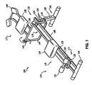
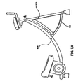
- FIG. 1 shows one abdominal exerciser 102 from the state of the art.
- Abdominal exerciser 102 has a front portion 132, rear portion 134 and contains rear support 104, forward support 106, track 108, sled 110, and upper body support 112.
- Rear support 104 rests on the ground and provides foundational support for abdominal exerciser 102.
- Rear support 104 may have a long tubular profile, a solid square or rectangular profile, or any other profile known in the art for use as support of a bench like structure similar to abdominal exerciser 102.
- Rear support 104 is attached to track 108.
- Track 108 can be made of metal, plastic with a metal or TEFLON® coating or some other material that has a relatively low coefficient of friction with the material used to make roller 128. In the preferred embodiment there are two tracks 108, however in other embodiments there may be only one track or, alternatively, more than two tracks. Track 108 extends from rear support 104 to forward support 106 and has a rear portion 114 proximate to rear support 104 and a forward portion 116 proximate to forward support 106. According to the present invention, track 108 is curved as shown in FIGS. 5A-5B . The curvature can be circular, ellipsoid, parabolic, or any other curved shape that advantageously affects the abdominal and oblique muscles.
- the front foundation includes a telescopic extension to raise the height of one end of the track to a desired level of inclination.
- Forward support 106 elevates forward portion 132 of track 108 at least approximately 6 inches off the ground and contains hollow outer base 118 and adjustable top portion 120 and provides foundational support for abdominal exerciser 102.
- Base 118 may have a long tubular profile, a solid square or rectangular profile, or any other profile known in the art for use as support for a bench like structure similar to abdominal exerciser 102.
- Adjustable top portion 120 is slidably mounted within outer base 118 in telescoping relation. By sliding the adjustable top portion 120 inwardly or outwardly relative to outer base 118, the overall length of forward support 106 can be selectively changed to vary the height of forward support 106.
- a locking means is provided for locking outer base 118 and adjustable top portion 120 in desired relative positions to create a desired length for forward support 106.
- the locking means includes at least one hole 129 in outer base 118 and a plurality of holes 130 in adjustable top portion 120 which can be selectively aligned with least one hole 129 in outer base 118.
- a pin member is constructed to be inserted in the aligned holes, thereby securely locking forward support 106 in the desired length.
- At least one hole 129 and holes 130 may be threaded holes, and the pin member may have cooperating threads to enable the pin to be threaded or screwed into the holes to secure forward support 106 at a desired length.
- Track 108 is secured to forward support 106 and forward support 106 elevates tracks 108 to a desired level, preferably at least approximately 6 inches above to provide an incline.
- Sled 110 glides along track 108.
- Sled 110 contains sled base 126. Attached to sled base 126 are instep pad 122, knee pad or leg support 124, and roller 128.
- Roller 128 may be made of metal, plastic with a metal or TEFLON ® coating or some other material that has a relatively low coefficient of friction on the material used to make track 108. In an alternate embodiment, roller 128 may be ball bearings, roller bearings or some other means which would allow sled 110 to travel along track 108 with a relatively low coefficient of friction.
- Instep pad 122 is made of dense foam, rubber, or some other similar material. The purpose of instep pad 122 is to elevate the feet to avoid interfering with the movement of the sled. Other means may be used to elevate the feet such as a wedge or the feet may not be elevated at all.
- knee pad 124 can pivot up to approximately 45 degrees to the right or left of a plane vertical to the center of sled 110. By pivoting knee pad 124 the oblique muscles can be effectively exercised.
- Sled 110 can travel the entire length of track 108 but preferably travels to the approximate area of upper body support 112.
- Upper body support 112 is attached to front portion 132 of abdominal exerciser 102 and comprises at least one handle 548.
- the upper body support 112 comprises an elevation bar 144 attached to the track 108 and at least one handle 548 attached to the elevation bar 144.
- the upper body support can comprise an elevation bar 144, a cross bar 136, an arm pad or arm support 138, and a chest pad or chest support 140.
- Elevation bar 144 is attached to track 108 such that sled 110 can travel past elevation bar 144.
- elevation bar 144 is attached to track 108 such that sled 110 cannot travel past elevation bar 144.
- elevation bar 144 may be attached to forward support 106.
- Cross bar 136 is pivotally attached to elevation bar 144 and suspend approximately 12 to 48 inches above track 108.
- Cross bar 136 is pivotally attached to elevation bars such that the amount of torque required to rotate cross bar 136 can be adjusted, preferably by tension control member 142.
- Tension control member 142 controls the amount of resistance required to rotate cross bar 136 and can be set such that cross bar 136 may be locked in any rotational position especially one where arm pad 138 has been rotated towards track 108.
- the handles 548 can be pivotally attached to the elevation bar 144 and suspended approximately 12 to approximately 48 inches above the track 108.
- Arm pad or arm support 138 is attached to cross bar 136, has a general rectangular or square profile, and is made of dense foam or some other similar material. Arm pad 138 provides support for the arms during use. Chest pad 140 is attached to arm pad 138 and elevated approximately 1 to 36 inches above arm pad 138. Chest pad 140 has a general cylindrical, rectangular, or square profile and is made of dense foam or some other similar material. Chest pad 140 provides support for the chest during use. In an alternate embodiment, a head support may be used to support the head. In addition, shoulder pads may be used in conjunction with or to replace chest pad 140. Other means to support the upper body of the user would be apparent to one skilled in the art.
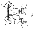
- the cross bar 136 is divided into two sections, right bar section 202 and left bar section 204.
- Right bar section 202 and left bar section 204 are pivotally attached to elevation bar 144 such that the torque required to rotate right bar section 202 and left bar section 204 can be adjusted, preferably by a tension control members 206 and/or 208 respectively.
- Tension control members 206 and 208 controls the amount of resistance required to rotate right bar section 202 and left bar section 204 and can be set such that right bar section 202 and left bar section 204 may be locked in any rotational position especially one where arm pad 138 has been rotated towards the track 108.
- Tension control members 206 and 208 have markings or slots such that each one can be set to the same tension as the other or only one tension control member may be used to control the amount of resistance required to rotate the upper body support 112.
- the chest pad 140 is also divided into two sections, right pad 210 and left pad 212. Right pad 210 and left pad 212 are attached to right bar section 202 and left bar section 204 respectively. In an alternate embodiment, chest pad 140 is a single one piece member.
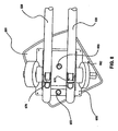
- FIG. 3 shows an alternate embodiment wherein upper body support 112 is pivoted when sled 110 is accelerated towards upper body support 112.
- the pivot means is a bell crank with pivot member 302 attached to elevation bar 144, lower arm 304 attached to sled 110, and upper arm 306 attached to upper body support 112.
- lower arm 304 pushes pivot member 302 causing it to rotate and pull down on upper arm 306, which causes upper body support 112 to rotate.
- a second function of the pivot means is to help accelerate sled 110 towards upper body support 112 by rotating upper body support 112 towards track 108.
- pivot means such as the bell crank
- other means may be used to pivot upper body support 112 when sled 110 is accelerated towards upper body support 112.
- other mechanical means similar to a bell crank or a cable and pulley system may be used to pivot upper body support 112 when sled 110 is accelerated towards upper body support 112.
- Resistance to sliding the sled is provided by a user's body weight working against gravity, as it is forced upward on the inclined tracks. Resistance can be increased or decreased by raising and lowering the level of incline.
- a resistance member 310 such as a spring, resistance band, or free weights attached to the sled, may be used for additional resistance. Resistance bands are elastic and attached to rear support 104 and sled 110.
- the forearms are positioned on upper body support 112 and the shins are positioned onto instep pads 122 on sled 110.
- Sled 110 is then accelerated towards upper body support 112 by bringing the knees as close as possible to upper body support 112 or the user's chin while keeping forearms positioned on upper body support 112.
- knee pad 124 By pivoting knee pad 124 up to approximately 45 degrees to the right or left of a plane vertical to the center of sled 110 the force needed to accelerate sled 110 can be supplied by the right or left oblique muscles.
- the knees may be brought as high as possible at the peak of the contracted point of both crunches, rendering a tight squeeze in a near fetal position.
- sled 110 is made to travel back and forth along track 108 while the legs and hips remaining locked at a 90 degree angle with respect to knee pad 124.
- sled 110 is made to travel back and forth along track 108 while cross bar 136 is locked in a desired position.
- the knees are allowed to freely move while sled 110 is accelerated towards upper body support 112 and cross bar 136 is pivoted towards track 108. Then, the upper and lower abdominal muscles are used to force sled 110 to travel back and forth along track 108 while cross bar 136 is pivoted towards track 108.
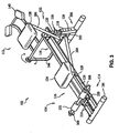
- FIG. 5A shows another preferred embodiment of the abdominal exerciser 500 to work the abdominal and oblique muscle groups and isolate the upper and lower abdominal muscles in a biometrically neutral position.
- the abdominal exerciser 500 can have a rear support 510, at least one track 520, a front support 530, an upper body support 540 and a sled 600 with a knee pad or leg support 550.
- the track 520 is an arcuate track 520.
- FIG. 5A shows the arcuate track 520 with a front portion 522 and a back portion 524 where the front portion 522 of the arcuate track 520 is attached to the front support 530 and the back portion 524 of the arcuate track 520 is attached to the rear support 510 such that the front portion 522 is at least approximately 6 inches off the ground.
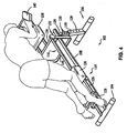
- this elevation causes the user to oppose the force of gravity by contracting the abdominal muscles when in the crunch position (see FIG. 7B ). It also allows the user to exercise in an upright, forward leaning position, much like a bicyclist's pose. This is convenient and familiar to most users and maintains the user's upper body in a fixed, still state allowing the user to read or watch a television show during an exercise.
- Track 520 can be curved as shown in FIG. 5A .
- the curvature can be circular, ellipsoid, parabolic, or any other curved shape that advantageously affects the abdominal and oblique muscles.
- the curved nature of the track 520 allows the user to roll his knees towards his chest (see FIG. 7B ). It is believed that rolling the knees towards the chest provides for a more effective and safe crunch style abdominal exercise as opposed to the traditional sit up where the person would only pivot at his hips, which could cause injury. Furthermore, the current invention eliminates or minimizes the ability to "cheat” since the entire motion can only be achieved with the abdominal muscles. In the traditional sit-up a person tends to put his hands behind his head pull his head with his arms to facilitate the exercise. This reduces the effectiveness of the exercise as well as creating strain on the neck. In other abdominal exercise devices that also provide for this rolling motion, the user lies on his back, grasps handles then rolls his back into a crunch. However, this again allows for "cheating” as the user could use his arms to facilitate the rolling process.
- the convex side of the curved track 520 rests on a support surface such as the floor.
- the track 520 can be curved both at the front portion 522 and the back portion 524, as shown in FIG. 5A , or the track can be curved at the front portion 522 only, as shown in FIGS. 5B , 6 , and 7A-7B . Having the curvature extend to the back end allows the user to exercise his lower back muscles as well.
- the knee pad or leg support 550 can be slidably mounted on the arcuate track 520.
- the sliding mechanism 570 can be a rolling element, such as wheels, a plurality of bearings, such as ball bearings or roller bearings, or a gliding mechanism such as a four bar linkage.
- the knee pad or leg support 550 can be mounted on the sled 600, where the sled 600 can be slidably mounted on the track 520, and preferably an arcuate track, 520 via the aforementioned mechanisms.
- the leg support 550 can be rotatably mounted to the sled 600.
- the leg support 550 can rotate up to approximately 45 degrees to the right or left of a plane vertical to the center of the sled 600. In other words, the leg support 550 can rotate up to approximately 45 degrees clockwise or counterclockwise about an axis 553 generally perpendicular to the arcuate track 520.
- the leg support 550 can have a first locking member 552 having a first position and a second position.
- the first locking member 552 for example, a lug or pin, disengages the leg support 550, allowing the leg support 550 to freely rotate about an axis 553 that is generally perpendicular to the arcuate track 520.
- This rotating, pivoting, or swiveling action allows the user to twist his lower body to the left or right while performing an abdominal crunch thereby exercising his left or right oblique abdominal muscles.
- the disengaged position the user can alternate exercising his left and right oblique abdominal muscles with each repetition.
- the leg support 550 In the second position the leg support 550 can be locked in a predetermined orientation relative to the sled 600.
- the leg support 550 can be locked at predetermined positions ranging from zero to about 45 degrees to the right or left of a plane vertical to the center of the sled 600.
- the locking member is a retractable lug member, pop pin, or pin and yoke configuration.
- the user wants the leg support 550 to be fixed at a particular angle during the exercise, whether the angle is parallel to the track, 45 degrees oblique to the track, or any angle in between, the user simply rotates the leg support 550 to the desired angle and moves the lug or pin 552 into the engaged position by inserting it into an indentation or recess 852 in the engagement surface.
- FIG. 8 shows one indentation or recess 852 there can be a plurality of indentations or recesses 852.
- the engagement surface of receptor block or yoke comprises a plurality of recesses 852, where each recess 852 is shaped to accept the lug or pin member 552.
- the lug 552 is spring activated, and releasing the lever causes a compression spring (not shown) to force the lug down towards the engagement surface.
- pin and yoke configurations are equally contemplated, however, within the present invention, including a cog and sprocket arrangement, or alternatively, a threaded pin that requires the user to press the pin into the desired hole, which is tapped with mating threads, and requires twisting the pin into the engaged position in the hole in order to lock the leg support 550 into a desired orientation.
- the pin and yoke combination could also be replaced with a mechanism comprising engaging teeth, such as a pawl and ratchet wheel, or other such clutch mechanism or one or many clamping configurations such as a tightening strap and tactile contact surface, or the like.
- the allowable angular positions of the leg support 550 may be discreet positions (such as with a pin and hole combination) or may be continuous (such as with other common clamping configurations).
- the leg support 550 may be freely pivoted about the pivot axis during an exercise, adding to the diversity of abdominal muscle exercises that can be performed.
- the lug may be removed from the surface and withheld from engaging any of the recesses 852 in the surface either by moving the lug to a plane offset from the recesses 852 or by retaining the lug in the disengaged position so that it is held away from the surface itself during the exercise.
- the user would release the first locking member 552 from an engaged position to a disengaged position before an exercise to allow the leg support 550 to pivot about a pivot axis, in which the leg support 550 can be locked at any one of a plurality of angles relative to a plane vertical to the center of the sled 600 based on the desired exercise such as in FIG. 8 .
- the knee pad or leg support 550 can be designed to provide a more supportive and more stylish leg support 550.
- the knee end can be indented and the ankle end can be raised so as to conform to the contours of the front portion of the average leg.
- the upper body support 540 is fixedly mounted in relation to the arcuate track 520. Having the upper body support 540 fixed allows the user to stabilize the upper body and focus the exercise on the abdominal muscles as shown in FIG. 7B . In addition to providing a more effective crunch, having the upper body support 540 fixed facilitates the user to engaging in other cognitive activities such as reading, watching television, or conversing with others.
- the upper body support 540 can have an elevation bar 542, a cross bar 544, and at least one arm pad or arm support 546. In another embodiment the upper body support 540 can have at least one handle 548 for the user to grasp during the exercise.
- the upper body support 540 can also have at least one chest pad and at least one head pad.
- the upper body support 540 can have a second locking member 549 for selectively adjusting the height of the upper body support 540.
- the second locking member 549 for selectively adjusting the height of the upper body support 540 can be on the elevation bar 542.
- the second locking member 549 such as a pop pin or any other locking member described previously, can be disengaged from the front support 530 to allow the upper body support 540 to slide up or down to a desired height, then the locking member can be re-engaged to lock the upper body support 540 in place at the desired height.
- the elevation bar 542 can be cylindrical in shape to provide a means for rotating the upper body support 540 without having to remove the elevation bar 542 from the front support 530.
- the elevation bar 542 can further have recesses on opposite sides such that the upper body support 540 can be arranged in at least two different orientations.
- the upper body support 540 can be pivotally attached to the front portion 522 of the arcuate track 520.
- the cross bar 544 of the upper body support 540 can be pivotally attached to the elevation bar 542 and suspended approximately 12 to approximately 48 inches above the arcuate track 520.
- the embodiments illustrated in FIGS. 5A and 5B show two such mechanisms for providing this adjustability of the upper body support 540, but other telescoping and gear mechanisms are equally contemplated and within the scope of the present invention.
- the handles 548 pivotally attached to the front portion 522 of the arcuate track 520 or the elevation bar 542 allows the handles 548 to pivot from a first position to at least a second position to perform a different type of exercise or isolate a different abdominal muscle group.
- the handles 548 can be above the track, in front of the arm pad 546 so that the user can grasp the handles 548 with his knuckles facing forward while resting his upper body on the arm pad 546 (see FIG. 7A and 7B ).
- the upper body support 540 can be rotated 180 degrees about an axis protruding up from the front support 530 and then tilted slightly downward by pivoting the upper body support 540 downward about an axis perpendicular to the front support 530 and to the arcuate tracks 520 so that when the user grasps the handles 548 his arms and elbows are tucked in near his rib cage with his knuckles facing a downward direction (see FIG. 5B ).
- the upper body can be placed in a second position by pivoting the handles 548 downward 180 degrees and rotating the upper body support 540 about an axis protruding from the longitudinal direction of the cross bar 544.
- the upper body support 540 or cross bar 544 can be detachably coupled to the elevation bar 542 with recesses for receiving a locking member on opposite sides such that the upper body support 540 can be rotated 180 degrees and locked back into the elevation bar 542 in a new orientation.
- the elevation bar 542 can be cylindrical such that when the locking member is disengaged, the upper body support 540 can be rotated into a new orientation without having to remove the upper body support 540 from the front support 530.
- the upper body support 540 can be pivotally coupled to the elevation bar 542 via any number of common pivot connections, such as a ball and socket or toothed mechanism. The downward rotation of the upper body support 540 can be accomplished with a variety of hinge-like mechanisms.
- the arm pad 546 can be removable so as not to cause interference with the normal use of the exercise device, particularly when the handles 548 of the exercise device are in the lowered position (see FIG. 5B ).
- the elbow portion of the arm pad 546 can be raised to prevent slippage during the exercise.
- the abdominal exercise machine 500 can further comprise a resistive or resistance member 560 to increase the resistance required to move the sled 600 or the leg support 550.
- the resistance member 560 can be on the leg support 550, the sled 600, or the arcuate track 520.
- the resistance member 560 can be weights, elastomer members, spring members, viscous members, pneumatic members, or any other means to increase the force required to move the sled 600 along the track.
- the leg support 550 or sled 600 can have a protrusion 554 to which weights can be added.
- one end of an elastomer, spring, or pneumatic member can be attached to the protrusion 554 and the other end of the elastomer, spring or pneumatic member can be attached to the front portion 522 or rear support 510.
- the degree of resistance can be changed by adding more weights, elastomer members, or spring members or by selecting heavier weights, elastomer members with lower elasticity, spring members with higher tension, pneumatic members with higher pressure or any combination thereof.
- Both the front support 530 and rear support 510 can each further comprise a third and fourth locking members 532 for selectively adjusting the height of the front portion 522 or back portion 524 of the track 520, and preferably an arcuate track 520, respectively (see FIG. 5A ).
- the third and fourth locking members 532 such as a pop pin or any other locking member described previously, can be disengaged from the front support 530 or rear support 510 to allow the front support 530 or rear support 510 to slide up or down to a desired height, then the third and fourth locking members 532 can be re-engaged to lock the front support 530 or rear support 510 in place at the desired height.
- FIG. 7A and 7B show the abdominal exerciser further comprising a stabilizing bar 700.
- the stabilizing bar 700 can be pivotally coupled to the track 520, and preferably an arcuate track 520, and detachably coupled to the front support 530.
- the front support 530 can be pivotally coupled to the arcuate track 520. This provides a means for folding up the exercise machine 500 when not in use.
- a user When a user has completed his exercise he can detach the stabilizing bar 700 from the front support 530 and pivot the stabilizing bar 700 up towards the front portion 522 of the arcuate track 520.
- the stabilizing bar 700 can then be attached to the front portion 522 of the arcuate track 520 or the top portion of the front support 530.
- the bottom portion of the front support 530 can be pivoted towards the middle portion of the arcuate track 520 and attached to the middle portion of the arcuate track 520.
- abdominal crunches can be accomplished by positioning the body on an abdominal exercise machine 500 and using the abdominal muscles to accelerate the sled 600 from the back portion 524 of the arcuate track 520, to the front portion 522 of the track 520 wherein the knees are on the sled 600 and the upper body is on the upper body support 540, and returning the sled 600 to its original or resting position, thereby completing a repetition.
- the user Prior to using the exercise machine 500, the user must set up the machine 500 to suit the user's specifications by adjusting the height of the upper body support 540 by disengaging the second locking member 549, adjusting the upper body support 540 to the desired height, and re-engaging the second locking member 549.
- the height of the track 520 can be adjusted by removing a third and fourth locking member, moving the front portion 522, the back portion 524, or both to the desired height, and re-engaging the third and fourth locking member.
- the user can adjust the positioning of the upper body support 540 by disengaging the second locking member 549, rotating the upper body support 540 180 degrees about an axis protruding longitudinally from the front support 530, then tilting the upper body support 540 downward until the handles 548 are in a desired lowered position, such that the elbows are near the ribcage. From this position the user can return the upper body support 540 to the original position by disengaging the second locking member 549, rotating the upper body support 540 180 degrees, then tilting- the upper body support 540 upward until the handles 548 are in the original position such that the elbows are positioned on the arm pad 546 in front of the body.
- the upper body support 540 can be re-positioned by rotating the handles 548 180 degrees downward, disengaging the second locking member 549, rotating the upper body support 540 about an axis protruding longitudinally from the cross bar 544, and reengaging the second locking member 549 when the handles 548 are in the desired position.
- the user can perform the exercise by placing the user's legs or knees on a leg support 550 slidably mounted to at least one arcuate track 520, placing the user's arms on an upper body support 540 fixedly mounted in relation to the track 520, pulling the user's legs and leg support 550 along the track towards the user's chin thereby performing a contraction of the user's abdominal muscles, moving the user's knees and leg support 550 along the track 520 away from the user's chin thereby allowing the user's abdominal muscles to relax and repeating the pulling and moving steps in order to exercise the user's abdominal muscles.
- an additional lower back exercise can be performed by including the steps of moving the leg support 550 towards the back portion 524 of the arcuate track 520 thereby contracting the user's lower back muscles, then moving the user's knees and leg support 550 along the arcuate track 520 away from the back portion 524 of the arcuate track 520 thereby relaxing the lower back and repeating these steps in order to exercise the lower back muscles.
- the intensity of the exercise can be modified by adding a resistive or resistance member 560 to the leg support 550, the sled 600, or the arcuate track 520.
- the user can select a desired weight, an elastomer member of a desired elasticity, a spring member of a desired tension, a viscous member of a desired viscosity, or a pneumatic member of a desired pressure.
- the resistive member 560 is a weight, the user can simply place the weight on a protrusion 554 from the sled 600 or leg support 550.
- the user can add a single desired weight or multiple weights to achieve the desired weight.
- the resistive member 560 is an elastomer member, a spring member, or a pneumatic member, the user can attach these members to the front or the rear support 530, 510 and the sled 600 or leg support 550.
- Further steps can include disengaging a leg support 550 by placing a first locking member 552 into a first position and rotating the leg support 550 to one side up to approximately 45 degrees about an axis generally perpendicular to the at least one arcuate track 520, performing a first repetition, rotating the leg support 550 to the other side up to approximately 45 degrees about an axis generally perpendicular to the at least one arcuate track 520, performing a second repetition, and repeating a plurality of repetitions while alternating the rotation of the leg support 550 from one side to another in between each repetition to complete a set of abdominal exercises. This allows the user to alternate exercising one oblique then the other during a set of exercises.
- An alternative step can include locking the leg support 550 in a predetermined position by placing the first locking member 552 into a second position such that the leg support 550 is rotated about an axis that is generally perpendicular to the at least one track, up to 45 degrees oblique from a forward direction, completing a plurality of repetitions to complete a set of abdominal exercises, disengaging the first locking member 552 and rotating and locking the leg support 550 in a second predetermined position, up to 45 degrees oblique from the forward direction, and completing a second plurality of repetitions to complete a second set of abdominal exercises.
- This allows the user to completely exercise one side of the oblique muscles then switch to exercising the other side.
- the present invention has a wide range of industrial applicability. Particularly, when configured and used in accordance with the general principles of the present invention, the abdominal exerciser advantageously minimizes and/or eliminates back and neck strain.
- the abdominal exerciser of the present invention may be easily adjusted to a user's personal specifications.
Landscapes
- Health & Medical Sciences (AREA)
- General Health & Medical Sciences (AREA)
- Physical Education & Sports Medicine (AREA)
- Life Sciences & Earth Sciences (AREA)
- Biophysics (AREA)
- Orthopedic Medicine & Surgery (AREA)
- Cardiology (AREA)
- Vascular Medicine (AREA)
- Rehabilitation Tools (AREA)
- Massaging Devices (AREA)
- Paper (AREA)
- Measurement Of The Respiration, Hearing Ability, Form, And Blood Characteristics Of Living Organisms (AREA)
Claims (9)
- Bauchtrainingsvorrichtung (500) zum Trainieren der Bauchmuskelgruppen und seitlichen Bauchmuskelgruppen und zum Isolieren der oberen und unteren Bauchmuskeln in einer biometrisch neutralen Lage, wobei die Bauchtrainingsvorrichtung Folgendes aufweist:eine Schiene (520);eine vordere Stütze (530), wobei die vordere Stütze (530) mit einem vorderen Bereich (522) der Schiene (520) verbunden ist und den vorderen Bereich (522) der Schiene (520) von dem Boden hochhebt;eine Oberkörperstütze (540), welche mit dem vorderen Bereich (522) der Schiene (520) verbunden ist;einen Schlitten (600), welcher auf der Schiene (520) gleiten kann, undeine Beinstütze (550), welche an dem Schlitten (600) angebracht ist;dadurch gekennzeichnet,dass die Oberkörperstütze (540) bezüglich der Schiene (520) fest angebracht ist unddass die Schiene eine bogenförmige Schiene (520) ist, wodurch einem Benutzer ermöglicht wird, seine Knie in Richtung seiner Brust zu rollen.
- Bauchtrainingsvorrichtung (500) nach Anspruch 1,
wobei die Beinstütze (550) drehbar an dem Schlitten (600) angebracht ist und dazu eingerichtet ist, sich um eine Rotationsachse (553), die im Wesentlichen senkrecht auf eine obere Oberfläche des Schlittens (600) steht, zu drehen, um einem Benutzer das Trainieren der seitlichen Muskelgruppe zu ermöglichen. - Bauchtrainingsvorrichtung (500) nach Anspruch 2,
wobei die Beinstütze (550) ein erstes Verschlussglied (552) mit einer ersten Position und einer zweiten Position aufweist,
wobei das erste Verschlussglied (552) in der ersten Position die Beinstütze (550) löst, wodurch die Beinstütze (550) frei um die Drehachse (553) drehbar ist, und
wobei das erste Verschlussglied in der zweiten Position die Beinstütze (550) in einer vorbestimmten Ausrichtung relativ zu dem Schlitten (600) arretiert, um die vom Benutzer gewünschte Übungsart zu variieren. - Bauchtrainingsvorrichtung (500) nach Anspruch 2,
wobei ein Bereich der Beinstütze (550) eine Mehrzahl an Vertiefungen (852) aufweist zur Aufnahme eines Bereichs des ersten Verschlussglieds (552) zum Arretieren der Beinstütze (550) in einem aus einer Mehrzahl von Winkeln schräg zu dem Weg des Schlittens (600) entlang der Schiene (520). - Ein Verfahren zum Trainieren der Bauchmuskelgruppen und seitlichen Bauchmuskelgruppen in einer biometrisch neutralen Lage, wobei das Verfahren die folgenden Schritte aufweist:Platzieren von Händen und Armen eines Benutzers auf einer Oberkörperstütze (540), welche an einer Schiene (520) angebracht ist, undPlatzieren von zumindest Bereichen der Beine des Benutzers auf einer Beinstütze (550), die gleitbar an der Schiene (520) angebracht ist;dadurch gekennzeichnet,dass die Schiene eine bogenförmige Schiene (520) ist unddass die Oberkörperstütze (540) bezüglich der Schiene (520) fest angebracht ist, undgekennzeichnet durch die Schritte,dass die Knie des Benutzers und die Beinstütze (550) entlang der bogenförmigen Schiene (520) in Richtung des Kinns des Benutzers gezogen werden, wodurch eine Kontraktion der Bauchmuskeln des Benutzers durchgeführt wird;dass die Knie des Benutzers und die Beinstütze (550) entlang der Schiene (520) weg von dem Kinn des Benutzers bewegt werden, wodurch eine Entspannung der Bauchmuskeln ermöglicht wird, unddass die Schritte des Ziehens und Bewegens zum Trainieren der Bauchmuskeln des Benutzers wiederholt werden.
- Das Verfahren nach Anspruch 5,
wobei die Beinstütze (550) an einer Gleitvorrichtung (570) angebracht ist, welche aus einer Gruppe umfassend eine Mehrzahl von Wälzkörpern, eine Mehrzahl von Lagern und ein Gelenkviereck ausgewählt ist. - Das Verfahren nach Anspruch 5,
wobei die Beinstütze (550) eine Mehrzahl von Vertiefungen (852) aufweist, zum Aufnehmen eines Bereichs eines ersten Verschlussglieds (552) und eines Gleitglieds, welches das erste Verschlussglied beherbergt,
wobei das erste Verschlussglied (552) eine erste Position und eine zweite Position aufweist,
so dass das erste Verschlussglied (552) in der ersten Position die Beinstütze löst, wodurch die Beinstütze (550) frei um eine Rotationsachse (553), welche im Wesentlichen senkrecht auf eine obere Oberfläche des Gleitglieds steht, gedreht werden kann, und
so dass das erste Verschlussglied (552) in der zweiten Position die Beinstütze (550) in einer vorbestimmten Ausrichtung relativ zu der oberen Oberfläche des Gleitglieds arretiert. - Das Verfahren nach Anspruch 7,
welches außerdem die folgenden Schritte aufweist:Lösen der Beinstützen (550) durch Stellen des ersten Verschlussglieds (552) in die erste Position;Drehen der Beinstütze (550) in einer ersten Richtung um eine Rotationsachse (553), welche im Wesentlichen senkrecht auf eine obere Oberfläche des Gleitglieds steht;Durchführen einer ersten Bauch- und seitlichen Bauchpresse;Drehen der Beinstütze (550) in der entgegengesetzten Richtung um die Rotationsachse (553);Durchführen einer zweiten Bauch- und seitlichen Bauchpresse und Wiederholen der vorausgehenden Drehungen und Bauchpressen zum Vervollständigen eines Bauchtrainingssatzes. - Das Verfahren nach Anspruch 7,
welches außerdem die folgenden Schritte aufweist:Arretieren der Beinstütze (550) in einem vorbestimmten Winkel schräg zu einer Vorwärtsrichtung undDurchführen einer Mehrzahl an Wiederholungen zum Vervollständigen eines Trainingssatzes sowohl der Bauch- als auch der seitlichen Bauchmuskelgruppen.
Applications Claiming Priority (2)
| Application Number | Priority Date | Filing Date | Title |
|---|---|---|---|
| US11/607,745 US7455633B2 (en) | 2005-01-05 | 2006-11-30 | Abdominal exerciser device |
| PCT/US2007/004173 WO2008066559A2 (en) | 2006-11-30 | 2007-02-15 | Abdominal exercise device |
Publications (3)
| Publication Number | Publication Date |
|---|---|
| EP2111268A2 EP2111268A2 (de) | 2009-10-28 |
| EP2111268A4 EP2111268A4 (de) | 2010-01-13 |
| EP2111268B1 true EP2111268B1 (de) | 2011-09-21 |
Family
ID=38952183
Family Applications (1)
| Application Number | Title | Priority Date | Filing Date |
|---|---|---|---|
| EP07750970A Active EP2111268B1 (de) | 2006-11-30 | 2007-02-15 | Bauchmuskeltrainingsvorrichtung |
Country Status (7)
| Country | Link |
|---|---|
| US (1) | US7455633B2 (de) |
| EP (1) | EP2111268B1 (de) |
| JP (2) | JP5314596B2 (de) |
| CN (1) | CN101534907B (de) |
| AT (1) | ATE525116T1 (de) |
| CA (1) | CA2606676C (de) |
| WO (1) | WO2008066559A2 (de) |
Cited By (1)
| Publication number | Priority date | Publication date | Assignee | Title |
|---|---|---|---|---|
| DE202015102636U1 (de) | 2015-05-22 | 2015-06-25 | Uwe Buschhorn | Abdominales Trainingsgerät |
Families Citing this family (72)
| Publication number | Priority date | Publication date | Assignee | Title |
|---|---|---|---|---|
| US7585263B2 (en) * | 2005-01-05 | 2009-09-08 | Ab Coasler Holdings, Inc. | Abdominal exercise machine |
| US7611445B2 (en) * | 2004-01-05 | 2009-11-03 | Ab Coaster Holdings, Inc. | Abdominal exercise machine |
| ITRA20060009A1 (it) * | 2006-02-10 | 2007-08-11 | Technogym Spa | Macchina ginnica. |
| US20080064577A1 (en) * | 2006-09-11 | 2008-03-13 | Pederson Kim M | Exercise Device for Exercising Core Muscles |
| US20080143067A1 (en) * | 2006-11-30 | 2008-06-19 | John Wicka | Device for controlling wheeled vehicles, wheeled vehicles incorporating such device and methods of operating the same |
| US20080261782A1 (en) * | 2007-01-23 | 2008-10-23 | Mark Campbell | Rowing Machine Simulators |
| US8608626B2 (en) | 2007-01-23 | 2013-12-17 | Rowperfect Pty Ltd | Rowing machine simulator |
| CA2723332C (en) | 2007-05-04 | 2015-07-14 | Rafael R. Medina | Bilaterally actuated sculling trainer |
| US7731637B2 (en) * | 2007-05-11 | 2010-06-08 | D Eredita Michael | Simulated rowing machine |
| CN101181662B (zh) * | 2007-12-18 | 2010-07-21 | 周利莎 | 俯卧式爬行健身器 |
| US7833136B2 (en) * | 2008-01-12 | 2010-11-16 | Bell Edward J | Rowing trainer |
| US20090181830A1 (en) * | 2008-01-15 | 2009-07-16 | Super Made Products Co., Ltd. | Fitness treadmill |
| US20100022367A1 (en) * | 2008-07-25 | 2010-01-28 | Stamina Products, Inc. | Abdominal exerciser |
| US8105221B2 (en) * | 2008-09-08 | 2012-01-31 | Robson Splane | Abdominal exercise device |
| US7927267B2 (en) * | 2008-09-08 | 2011-04-19 | Robson Splane | Abdominal exercise device |
| JP2010088757A (ja) * | 2008-10-10 | 2010-04-22 | Dong-He Wu | 主動に曲伸可能な体操器具 |
| US7846074B2 (en) * | 2008-10-31 | 2010-12-07 | Strength Master Fitness Tech. Co., Ltd. | Recumbent exerciser |
| US7651446B1 (en) | 2008-11-13 | 2010-01-26 | Paul William Eschenbach | Elliptical core cycle exercise apparatus |
| US7662076B1 (en) * | 2008-12-29 | 2010-02-16 | Wei-Teh Ho | Exercising machine |
| US7780585B1 (en) * | 2009-02-24 | 2010-08-24 | Esperanza Cruz | Portable dual incline adjustable resistance abdominal muscle exercise machine |
| CN201404628Y (zh) * | 2009-04-09 | 2010-02-17 | 厦门康硕健身器材有限公司 | 一种滑移式健腹器 |
| AU2012100146B4 (en) * | 2009-04-09 | 2013-02-28 | Fitworx, Llc | A sliding abdominal exercise machine |
| US8057362B2 (en) * | 2009-06-12 | 2011-11-15 | Yasser Nadim | Exercise device and method of using same |
| US7955240B2 (en) * | 2009-06-12 | 2011-06-07 | Yasser Nadim | Exercise device and method of using same |
| CN201482070U (zh) * | 2009-08-07 | 2010-05-26 | 漳浦隆宝工业有限公司 | 健腹机 |
| US8043199B1 (en) * | 2010-05-06 | 2011-10-25 | Jerry Barker | Exercise machine |
| US7878957B1 (en) * | 2010-05-26 | 2011-02-01 | Yi-Fan Chen | Multi-functional exercising machine |
| US8118720B2 (en) * | 2010-06-08 | 2012-02-21 | Sebastian Scott M | Abdominal exercise and training apparatus |
| TWM397267U (en) * | 2010-07-20 | 2011-02-01 | Zhu Zhen Gang | Oscillation exercise device |
| BRMU9002222U2 (pt) | 2010-11-10 | 2013-03-05 | Icon Ip Inc | sistema e mÉtodo para fazer ginÁstica |
| USD660383S1 (en) | 2010-12-03 | 2012-05-22 | Icon Ip, Inc. | Dual curved support for an exercise device |
| USD659777S1 (en) | 2010-12-03 | 2012-05-15 | Icon Ip, Inc. | Exercise device |
| KR101288507B1 (ko) | 2011-09-16 | 2013-07-26 | 김영기 | 척추 운동 장치 |
| TWI472357B (zh) * | 2011-11-11 | 2015-02-11 | Icon Ip Inc | 可調式腹部運動裝置 |
| TWM429498U (en) * | 2011-11-18 | 2012-05-21 | yu-zhi Zhou | Abdomen stretching equipment with retractable and angle adjustable foot stand |
| US9630041B2 (en) | 2011-12-19 | 2017-04-25 | Joseph K. Ellis | Abdominal muscle exercise machine |
| US9770623B2 (en) | 2011-12-19 | 2017-09-26 | Joseph K. Ellis | Upper and lower body press exercise machine |
| US9873016B2 (en) | 2011-12-19 | 2018-01-23 | Ellis I.P., Inc. | Upper and lower body multi-press exercise machine |
| US8888661B2 (en) | 2011-12-19 | 2014-11-18 | Joseph K. Ellis | Abdominal muscle exercise machine |
| CN104884133B (zh) | 2013-03-14 | 2018-02-23 | 艾肯运动与健康公司 | 具有飞轮的力量训练设备 |
| US9370679B2 (en) * | 2013-08-26 | 2016-06-21 | Spx Fitness, Inc. | Multi-axis adjustable exercise machine |
| USD734409S1 (en) * | 2013-10-17 | 2015-07-14 | Total Gym Global Corp. | Exercise device |
| US9403047B2 (en) | 2013-12-26 | 2016-08-02 | Icon Health & Fitness, Inc. | Magnetic resistance mechanism in a cable machine |
| US9868023B2 (en) | 2014-02-06 | 2018-01-16 | James Darryl Boykin | Sliding exercise device with a plurality of tracks |
| WO2015191445A1 (en) | 2014-06-09 | 2015-12-17 | Icon Health & Fitness, Inc. | Cable system incorporated into a treadmill |
| CN104740835B (zh) * | 2015-04-13 | 2017-01-25 | 丽水学院 | 一种锻炼用调节式腹肌板机构 |
| US10343005B2 (en) * | 2015-05-26 | 2019-07-09 | Robson Lindsay Splane, Jr. | Exercise machine |
| CN104941141A (zh) * | 2015-07-04 | 2015-09-30 | 苏州塔可盛电子科技有限公司 | 一种股关节置换术后的康复装置 |
| US10426991B2 (en) * | 2015-07-15 | 2019-10-01 | Larry W. Barnett | Exercise device |
| US10940360B2 (en) | 2015-08-26 | 2021-03-09 | Icon Health & Fitness, Inc. | Strength exercise mechanisms |
| TWI644702B (zh) | 2015-08-26 | 2018-12-21 | 美商愛康運動與健康公司 | 力量運動機械裝置 |
| US11794066B2 (en) * | 2015-08-31 | 2023-10-24 | Joseph K. Ellis | Upper and lower body reciprocating arcing motion exercise machine with an adjustable angle user support |
| US11524206B2 (en) | 2015-08-31 | 2022-12-13 | Joseph K. Ellis | Upper and lower body push and pull exercise machine with a one directional resistance mechanism and adjustable angle |
| US12330019B2 (en) | 2015-08-31 | 2025-06-17 | Product Design Innovations, Llc | Upper and lower body reciprocating arcing motion exercise machine with an adjustable angle user support |
| US10653914B2 (en) | 2015-08-31 | 2020-05-19 | Product Design Innovations, Llc | Upper and lower body push and pull exercise machine with a one directional resistance mechanism and adjustable angle |
| US10212994B2 (en) | 2015-11-02 | 2019-02-26 | Icon Health & Fitness, Inc. | Smart watch band |
| US9814927B2 (en) | 2016-02-26 | 2017-11-14 | Leon Forystek | Abdominal exercise apparatus |
| US10441840B2 (en) | 2016-03-18 | 2019-10-15 | Icon Health & Fitness, Inc. | Collapsible strength exercise machine |
| US10293211B2 (en) | 2016-03-18 | 2019-05-21 | Icon Health & Fitness, Inc. | Coordinated weight selection |
| US10569127B2 (en) * | 2016-04-20 | 2020-02-25 | Nabile Innovations, Llc | Core exercise machine |
| US10252109B2 (en) | 2016-05-13 | 2019-04-09 | Icon Health & Fitness, Inc. | Weight platform treadmill |
| CN106166369B (zh) * | 2016-08-19 | 2019-10-01 | 南京新恒鼎体育科技发展有限公司 | 一种少女塑体练习机 |
| US10661114B2 (en) | 2016-11-01 | 2020-05-26 | Icon Health & Fitness, Inc. | Body weight lift mechanism on treadmill |
| USD848553S1 (en) * | 2017-11-02 | 2019-05-14 | ALLTrand, Inc. | Torso trainer |
| US10821318B2 (en) * | 2018-04-25 | 2020-11-03 | Freddy Saddler | Exercising assembly |
| CN109663284B (zh) * | 2019-01-07 | 2020-05-26 | 宜春学院 | 一种快速训练腹肌的智能健身装置 |
| US11123257B2 (en) * | 2019-08-20 | 2021-09-21 | Joseph Crocco | Foam glide |
| US12053664B2 (en) * | 2019-09-20 | 2024-08-06 | Ronald Williams | Exercise device |
| CN111013084B (zh) * | 2019-12-26 | 2024-08-23 | 上海金矢机器人科技有限公司 | 一种用于骨盆康复训练的弹簧阻尼系统 |
| US11291880B1 (en) | 2020-09-25 | 2022-04-05 | Rueben Arizmendez | Crawling workout apparatus |
| CN220824439U (zh) * | 2023-09-18 | 2024-04-23 | 义乌市悠颜觅厨科技有限公司 | 手柄可收纳的健身滑动件及健身器材 |
| US12478831B1 (en) | 2024-03-12 | 2025-11-25 | Anthony L. Blue, Jr. | Burpee exercise machine |
Family Cites Families (43)
| Publication number | Priority date | Publication date | Assignee | Title |
|---|---|---|---|---|
| US567915A (en) | 1896-09-15 | Bathing apparatus | ||
| US326447A (en) * | 1885-09-15 | Feeder for roller-mills | ||
| DE7930162U1 (de) | 1980-01-31 | Pichlmeier, Josef, 8251 Buchbach | Ski-Heimtrainer | |
| US2183345A (en) | 1939-01-21 | 1939-12-12 | Alfred E Brandon | Boat for exercises |
| US3759511A (en) * | 1971-03-29 | 1973-09-18 | K Gustafson | Adjustable friction type exercising device |
| US4176836A (en) | 1977-06-21 | 1979-12-04 | Randy Coyle | Variable resistance exercising apparatus and method |
| US4846465A (en) * | 1986-03-25 | 1989-07-11 | Superspine, Inc. | Method for manipulation of a person's truncal muscles and spine |
| US4930769A (en) | 1986-12-08 | 1990-06-05 | Nenoff Joseph R | Unified pull-push exercise device |
| US5224909A (en) * | 1992-05-04 | 1993-07-06 | Hamilton John R | Mid-body exercise device |
| US5376053A (en) * | 1993-08-02 | 1994-12-27 | Ponder; Patricia D. | Remotely operated motorized swing |
| CA2133251C (en) * | 1993-09-30 | 1999-01-12 | Gary D. Piaget | Striding exerciser with upwardly curved tracks |
| US5429567A (en) | 1993-11-01 | 1995-07-04 | Stamina Products, Inc. | Cross-country and downhill slalom skiing exercise machine |
| US5518483A (en) | 1994-05-10 | 1996-05-21 | Oswald; John C. | Portable push-pull type exercise device |
| US5527249A (en) | 1995-07-11 | 1996-06-18 | Harris; Robert W. | Multi-function exercise machine making use of body weight |
| US5620403A (en) | 1995-09-29 | 1997-04-15 | Physiq, Inc. | Sliding exercise machine |
| USD397745S (en) | 1996-05-03 | 1998-09-01 | Tai Fu Wu | Curved ski type exercise apparatus |
| US5746688A (en) * | 1997-05-13 | 1998-05-05 | Prager; Howard A. | Exercise device |
| CA2272167A1 (en) * | 1998-06-11 | 1999-12-11 | Jan J. P. Prsala | Fitness and body posture exercise apparatus |
| US6196954B1 (en) * | 1999-02-04 | 2001-03-06 | Wu Tsung Chen | Sliding exerciser |
| USD425585S (en) | 1999-02-26 | 2000-05-23 | World Famous Trading Company | Top and sides of abdominal exerciser |
| US6440045B1 (en) | 1999-04-22 | 2002-08-27 | Kerry R. Gaston | Abdominal exercise apparatus and method |
| US6183397B1 (en) | 1999-05-25 | 2001-02-06 | Kenneth W. Stearns | Multi-functional exercise methods and apparatus |
| US6244995B1 (en) | 1999-06-02 | 2001-06-12 | Jan Prsala | Fitness exercise apparatus—the slider |
| US6645129B2 (en) * | 2000-07-24 | 2003-11-11 | Paul William Eschenbach | Recumbent exercise apparatus with leg curl |
| US6634996B2 (en) | 2001-01-16 | 2003-10-21 | Neill Jacobsen | Exercise apparatus |
| US6491607B2 (en) * | 2001-03-06 | 2002-12-10 | Louis J. Simmons | Apparatus and method for lower back exercise |
| US20030022770A1 (en) | 2001-07-24 | 2003-01-30 | Long-Huei Lee | Elastic cord exercise machine with slack take-up mechanism |
| JP2003295218A (ja) * | 2002-04-04 | 2003-10-15 | Advanced Display Inc | 表示装置 |
| US7229394B1 (en) | 2002-08-05 | 2007-06-12 | Timothy Tyree | Workout equipment |
| WO2004075998A2 (en) | 2003-02-26 | 2004-09-10 | Engineering Fitness International Corp. | Exercise device and method of using same |
| CN2614729Y (zh) * | 2003-04-27 | 2004-05-12 | 朱子仁 | 俯卧撑练习器 |
| US7244217B2 (en) | 2003-06-06 | 2007-07-17 | Rodgers Jr Robert E | Exercise apparatus that allows user varied stride length |
| US7125371B2 (en) * | 2003-07-02 | 2006-10-24 | Alasdair David Henderson | Adjustable bodyweight exercise apparatus |
| US7083556B1 (en) * | 2003-07-23 | 2006-08-01 | Pete Miskech | Exercise apparatus |
| US20050085348A1 (en) | 2003-10-17 | 2005-04-21 | Kiefer Thomas N. | Apparatus for the improvement of rowing technique |
| CN2666493Y (zh) * | 2003-11-19 | 2004-12-29 | 上海上鹏运动器械有限公司 | 俯卧撑健身器 |
| US7232404B2 (en) | 2004-01-05 | 2007-06-19 | Tristar Products, Inc. | Abdominal exercise machine |
| US7585263B2 (en) | 2005-01-05 | 2009-09-08 | Ab Coasler Holdings, Inc. | Abdominal exercise machine |
| US7691041B2 (en) | 2004-11-09 | 2010-04-06 | Abdo John S | Exercise machine |
| US7179212B2 (en) * | 2004-12-01 | 2007-02-20 | Hupa International, Inc. | Omni-directional abdominal exerciser |
| US7485079B2 (en) * | 2005-01-05 | 2009-02-03 | Ab Coaster Holdings, Inc. | Abdominal exercise machine |
| USD565134S1 (en) * | 2005-01-05 | 2008-03-25 | Abcoaster Holdings Llc | Abdominal exercise device |
| GB0517691D0 (en) | 2005-08-31 | 2005-10-05 | Progressive Sports Technologies Ltd | Abdominal training apparatus |
-
2006
- 2006-11-30 US US11/607,745 patent/US7455633B2/en not_active Expired - Lifetime
-
2007
- 2007-02-15 EP EP07750970A patent/EP2111268B1/de active Active
- 2007-02-15 WO PCT/US2007/004173 patent/WO2008066559A2/en not_active Ceased
- 2007-02-15 JP JP2009539235A patent/JP5314596B2/ja active Active
- 2007-02-15 CA CA2606676A patent/CA2606676C/en not_active Expired - Fee Related
- 2007-02-15 CN CN2007800001252A patent/CN101534907B/zh active Active
- 2007-02-15 AT AT07750970T patent/ATE525116T1/de not_active IP Right Cessation
-
2013
- 2013-02-20 JP JP2013030642A patent/JP2013121550A/ja not_active Ceased
Cited By (2)
| Publication number | Priority date | Publication date | Assignee | Title |
|---|---|---|---|---|
| DE202015102636U1 (de) | 2015-05-22 | 2015-06-25 | Uwe Buschhorn | Abdominales Trainingsgerät |
| DE102016106902A1 (de) | 2015-05-22 | 2016-11-24 | Uwe Buschhorn | Abdominales Trainingsgerät |
Also Published As
| Publication number | Publication date |
|---|---|
| JP2013121550A (ja) | 2013-06-20 |
| JP2010511425A (ja) | 2010-04-15 |
| CN101534907A (zh) | 2009-09-16 |
| CN101534907B (zh) | 2013-04-10 |
| ATE525116T1 (de) | 2011-10-15 |
| EP2111268A4 (de) | 2010-01-13 |
| US20070149370A1 (en) | 2007-06-28 |
| US7455633B2 (en) | 2008-11-25 |
| CA2606676A1 (en) | 2008-01-16 |
| WO2008066559A2 (en) | 2008-06-05 |
| WO2008066559A3 (en) | 2009-04-30 |
| EP2111268A2 (de) | 2009-10-28 |
| JP5314596B2 (ja) | 2013-10-16 |
| CA2606676C (en) | 2014-09-09 |
Similar Documents
| Publication | Publication Date | Title |
|---|---|---|
| EP2111268B1 (de) | Bauchmuskeltrainingsvorrichtung | |
| US7485079B2 (en) | Abdominal exercise machine | |
| US7585263B2 (en) | Abdominal exercise machine | |
| US7611445B2 (en) | Abdominal exercise machine | |
| US7232404B2 (en) | Abdominal exercise machine | |
| US5746688A (en) | Exercise device | |
| US10426991B2 (en) | Exercise device | |
| EP2163280B1 (de) | Bauchübungsgerät | |
| US7309303B1 (en) | Exercising and physiotherapy system | |
| JP2010511425A5 (de) | ||
| US20160332024A1 (en) | Multi-functional exercise machine | |
| US6544151B2 (en) | Exercise apparatus | |
| US20140364285A1 (en) | Independent upper and lower body exercise equipment components and methods of using the same | |
| US20170239515A1 (en) | Apparatus for physical exercises | |
| WO2015138279A1 (en) | Multi-functional exercise machine | |
| US5632710A (en) | Exercise apparatus | |
| US7604580B2 (en) | Exercise device and method | |
| FI127760B (fi) | Kuntoutuslaite ja sen käyttö olkapään alueen harjoittamiseen | |
| US20170304676A1 (en) | Core exercise machine | |
| WO1992018204A1 (en) | Exercise device | |
| CN214286552U (zh) | 锻炼装置 | |
| WO2004043548A1 (en) | Exercise apparatus | |
| WO2016094116A1 (en) | Upper and lower body press exercise machine | |
| GB2509920A (en) | A compact rowing machine providing additional exercises | |
| KR20250148867A (ko) | 전신운동기구 |
Legal Events
| Date | Code | Title | Description |
|---|---|---|---|
| PUAI | Public reference made under article 153(3) epc to a published international application that has entered the european phase |
Free format text: ORIGINAL CODE: 0009012 |
|
| 17P | Request for examination filed |
Effective date: 20090804 |
|
| AK | Designated contracting states |
Kind code of ref document: A2 Designated state(s): AT BE BG CH CY CZ DE DK EE ES FI FR GB GR HU IE IS IT LI LT LU LV MC NL PL PT RO SE SI SK TR |
|
| TPAC | Observations filed by third parties |
Free format text: ORIGINAL CODE: EPIDOSNTIPA |
|
| RBV | Designated contracting states (corrected) |
Designated state(s): AT BE BG CH CY CZ DE DK EE ES FI FR GB GR HU IE IS IT LI LT LU LV MC NL PL PT RO SE SI SK TR |
|
| A4 | Supplementary search report drawn up and despatched |
Effective date: 20091210 |
|
| RAP1 | Party data changed (applicant data changed or rights of an application transferred) |
Owner name: AB COASTER HOLDINGS, INC |
|
| DAX | Request for extension of the european patent (deleted) | ||
| 17Q | First examination report despatched |
Effective date: 20100323 |
|
| GRAP | Despatch of communication of intention to grant a patent |
Free format text: ORIGINAL CODE: EPIDOSNIGR1 |
|
| RIC1 | Information provided on ipc code assigned before grant |
Ipc: A63B 21/00 20060101ALI20110120BHEP Ipc: A63B 26/00 20060101AFI20110120BHEP |
|
| GRAS | Grant fee paid |
Free format text: ORIGINAL CODE: EPIDOSNIGR3 |
|
| GRAA | (expected) grant |
Free format text: ORIGINAL CODE: 0009210 |
|
| AK | Designated contracting states |
Kind code of ref document: B1 Designated state(s): AT BE BG CH CY CZ DE DK EE ES FI FR GB GR HU IE IS IT LI LT LU LV MC NL PL PT RO SE SI SK TR |
|
| REG | Reference to a national code |
Ref country code: GB Ref legal event code: FG4D |
|
| REG | Reference to a national code |
Ref country code: CH Ref legal event code: EP |
|
| REG | Reference to a national code |
Ref country code: IE Ref legal event code: FG4D |
|
| REG | Reference to a national code |
Ref country code: DE Ref legal event code: R096 Ref document number: 602007017382 Country of ref document: DE Effective date: 20111124 |
|
| REG | Reference to a national code |
Ref country code: NL Ref legal event code: VDEP Effective date: 20110921 |
|
| PG25 | Lapsed in a contracting state [announced via postgrant information from national office to epo] |
Ref country code: SE Free format text: LAPSE BECAUSE OF FAILURE TO SUBMIT A TRANSLATION OF THE DESCRIPTION OR TO PAY THE FEE WITHIN THE PRESCRIBED TIME-LIMIT Effective date: 20110921 Ref country code: LT Free format text: LAPSE BECAUSE OF FAILURE TO SUBMIT A TRANSLATION OF THE DESCRIPTION OR TO PAY THE FEE WITHIN THE PRESCRIBED TIME-LIMIT Effective date: 20110921 Ref country code: FI Free format text: LAPSE BECAUSE OF FAILURE TO SUBMIT A TRANSLATION OF THE DESCRIPTION OR TO PAY THE FEE WITHIN THE PRESCRIBED TIME-LIMIT Effective date: 20110921 |
|
| LTIE | Lt: invalidation of european patent or patent extension |
Effective date: 20110921 |
|
| PG25 | Lapsed in a contracting state [announced via postgrant information from national office to epo] |
Ref country code: GR Free format text: LAPSE BECAUSE OF FAILURE TO SUBMIT A TRANSLATION OF THE DESCRIPTION OR TO PAY THE FEE WITHIN THE PRESCRIBED TIME-LIMIT Effective date: 20111222 Ref country code: LV Free format text: LAPSE BECAUSE OF FAILURE TO SUBMIT A TRANSLATION OF THE DESCRIPTION OR TO PAY THE FEE WITHIN THE PRESCRIBED TIME-LIMIT Effective date: 20110921 Ref country code: CY Free format text: LAPSE BECAUSE OF FAILURE TO SUBMIT A TRANSLATION OF THE DESCRIPTION OR TO PAY THE FEE WITHIN THE PRESCRIBED TIME-LIMIT Effective date: 20110921 Ref country code: SI Free format text: LAPSE BECAUSE OF FAILURE TO SUBMIT A TRANSLATION OF THE DESCRIPTION OR TO PAY THE FEE WITHIN THE PRESCRIBED TIME-LIMIT Effective date: 20110921 Ref country code: AT Free format text: LAPSE BECAUSE OF FAILURE TO SUBMIT A TRANSLATION OF THE DESCRIPTION OR TO PAY THE FEE WITHIN THE PRESCRIBED TIME-LIMIT Effective date: 20110921 |
|
| REG | Reference to a national code |
Ref country code: AT Ref legal event code: MK05 Ref document number: 525116 Country of ref document: AT Kind code of ref document: T Effective date: 20110921 |
|
| PG25 | Lapsed in a contracting state [announced via postgrant information from national office to epo] |
Ref country code: BE Free format text: LAPSE BECAUSE OF FAILURE TO SUBMIT A TRANSLATION OF THE DESCRIPTION OR TO PAY THE FEE WITHIN THE PRESCRIBED TIME-LIMIT Effective date: 20110921 |
|
| PG25 | Lapsed in a contracting state [announced via postgrant information from national office to epo] |
Ref country code: CZ Free format text: LAPSE BECAUSE OF FAILURE TO SUBMIT A TRANSLATION OF THE DESCRIPTION OR TO PAY THE FEE WITHIN THE PRESCRIBED TIME-LIMIT Effective date: 20110921 Ref country code: SK Free format text: LAPSE BECAUSE OF FAILURE TO SUBMIT A TRANSLATION OF THE DESCRIPTION OR TO PAY THE FEE WITHIN THE PRESCRIBED TIME-LIMIT Effective date: 20110921 Ref country code: IS Free format text: LAPSE BECAUSE OF FAILURE TO SUBMIT A TRANSLATION OF THE DESCRIPTION OR TO PAY THE FEE WITHIN THE PRESCRIBED TIME-LIMIT Effective date: 20120121 |
|
| PG25 | Lapsed in a contracting state [announced via postgrant information from national office to epo] |
Ref country code: EE Free format text: LAPSE BECAUSE OF FAILURE TO SUBMIT A TRANSLATION OF THE DESCRIPTION OR TO PAY THE FEE WITHIN THE PRESCRIBED TIME-LIMIT Effective date: 20110921 Ref country code: PL Free format text: LAPSE BECAUSE OF FAILURE TO SUBMIT A TRANSLATION OF THE DESCRIPTION OR TO PAY THE FEE WITHIN THE PRESCRIBED TIME-LIMIT Effective date: 20110921 Ref country code: PT Free format text: LAPSE BECAUSE OF FAILURE TO SUBMIT A TRANSLATION OF THE DESCRIPTION OR TO PAY THE FEE WITHIN THE PRESCRIBED TIME-LIMIT Effective date: 20120123 Ref country code: IT Free format text: LAPSE BECAUSE OF FAILURE TO SUBMIT A TRANSLATION OF THE DESCRIPTION OR TO PAY THE FEE WITHIN THE PRESCRIBED TIME-LIMIT Effective date: 20110921 Ref country code: NL Free format text: LAPSE BECAUSE OF FAILURE TO SUBMIT A TRANSLATION OF THE DESCRIPTION OR TO PAY THE FEE WITHIN THE PRESCRIBED TIME-LIMIT Effective date: 20110921 Ref country code: RO Free format text: LAPSE BECAUSE OF FAILURE TO SUBMIT A TRANSLATION OF THE DESCRIPTION OR TO PAY THE FEE WITHIN THE PRESCRIBED TIME-LIMIT Effective date: 20110921 |
|
| PLBE | No opposition filed within time limit |
Free format text: ORIGINAL CODE: 0009261 |
|
| STAA | Information on the status of an ep patent application or granted ep patent |
Free format text: STATUS: NO OPPOSITION FILED WITHIN TIME LIMIT |
|
| PG25 | Lapsed in a contracting state [announced via postgrant information from national office to epo] |
Ref country code: DK Free format text: LAPSE BECAUSE OF FAILURE TO SUBMIT A TRANSLATION OF THE DESCRIPTION OR TO PAY THE FEE WITHIN THE PRESCRIBED TIME-LIMIT Effective date: 20110921 |
|
| 26N | No opposition filed |
Effective date: 20120622 |
|
| PG25 | Lapsed in a contracting state [announced via postgrant information from national office to epo] |
Ref country code: MC Free format text: LAPSE BECAUSE OF NON-PAYMENT OF DUE FEES Effective date: 20120229 |
|
| REG | Reference to a national code |
Ref country code: CH Ref legal event code: PL |
|
| REG | Reference to a national code |
Ref country code: DE Ref legal event code: R097 Ref document number: 602007017382 Country of ref document: DE Effective date: 20120622 |
|
| PG25 | Lapsed in a contracting state [announced via postgrant information from national office to epo] |
Ref country code: CH Free format text: LAPSE BECAUSE OF NON-PAYMENT OF DUE FEES Effective date: 20120229 Ref country code: LI Free format text: LAPSE BECAUSE OF NON-PAYMENT OF DUE FEES Effective date: 20120229 |
|
| PG25 | Lapsed in a contracting state [announced via postgrant information from national office to epo] |
Ref country code: ES Free format text: LAPSE BECAUSE OF FAILURE TO SUBMIT A TRANSLATION OF THE DESCRIPTION OR TO PAY THE FEE WITHIN THE PRESCRIBED TIME-LIMIT Effective date: 20120101 |
|
| PG25 | Lapsed in a contracting state [announced via postgrant information from national office to epo] |
Ref country code: BG Free format text: LAPSE BECAUSE OF FAILURE TO SUBMIT A TRANSLATION OF THE DESCRIPTION OR TO PAY THE FEE WITHIN THE PRESCRIBED TIME-LIMIT Effective date: 20111221 |
|
| PG25 | Lapsed in a contracting state [announced via postgrant information from national office to epo] |
Ref country code: TR Free format text: LAPSE BECAUSE OF FAILURE TO SUBMIT A TRANSLATION OF THE DESCRIPTION OR TO PAY THE FEE WITHIN THE PRESCRIBED TIME-LIMIT Effective date: 20110921 |
|
| PG25 | Lapsed in a contracting state [announced via postgrant information from national office to epo] |
Ref country code: LU Free format text: LAPSE BECAUSE OF NON-PAYMENT OF DUE FEES Effective date: 20120215 |
|
| PG25 | Lapsed in a contracting state [announced via postgrant information from national office to epo] |
Ref country code: HU Free format text: LAPSE BECAUSE OF FAILURE TO SUBMIT A TRANSLATION OF THE DESCRIPTION OR TO PAY THE FEE WITHIN THE PRESCRIBED TIME-LIMIT Effective date: 20070215 |
|
| PGFP | Annual fee paid to national office [announced via postgrant information from national office to epo] |
Ref country code: IE Payment date: 20160527 Year of fee payment: 10 |
|
| REG | Reference to a national code |
Ref country code: FR Ref legal event code: PLFP Year of fee payment: 10 |
|
| REG | Reference to a national code |
Ref country code: FR Ref legal event code: PLFP Year of fee payment: 11 |
|
| REG | Reference to a national code |
Ref country code: IE Ref legal event code: MM4A |
|
| REG | Reference to a national code |
Ref country code: FR Ref legal event code: PLFP Year of fee payment: 12 |
|
| PG25 | Lapsed in a contracting state [announced via postgrant information from national office to epo] |
Ref country code: IE Free format text: LAPSE BECAUSE OF NON-PAYMENT OF DUE FEES Effective date: 20170215 |
|
| REG | Reference to a national code |
Ref country code: DE Ref legal event code: R082 Ref document number: 602007017382 Country of ref document: DE Representative=s name: WUNDERLICH & HEIM PATENTANWAELTE PARTNERSCHAFT, DE |
|
| PGFP | Annual fee paid to national office [announced via postgrant information from national office to epo] |
Ref country code: FR Payment date: 20220209 Year of fee payment: 16 |
|
| P01 | Opt-out of the competence of the unified patent court (upc) registered |
Effective date: 20230526 |
|
| PG25 | Lapsed in a contracting state [announced via postgrant information from national office to epo] |
Ref country code: FR Free format text: LAPSE BECAUSE OF NON-PAYMENT OF DUE FEES Effective date: 20230228 |
|
| PGFP | Annual fee paid to national office [announced via postgrant information from national office to epo] |
Ref country code: DE Payment date: 20250114 Year of fee payment: 19 |
|
| PGFP | Annual fee paid to national office [announced via postgrant information from national office to epo] |
Ref country code: GB Payment date: 20250109 Year of fee payment: 19 |