EP2107663A1 - Système de source de puissance, procédé de commande de source de puissance pour le système de source de puissance, programme de commande d'alimentation électrique pour le système de source de puissance, et support d'enregistrement lisible par ordinateur avec programme de commande d'alimentation é - Google Patents
Système de source de puissance, procédé de commande de source de puissance pour le système de source de puissance, programme de commande d'alimentation électrique pour le système de source de puissance, et support d'enregistrement lisible par ordinateur avec programme de commande d'alimentation é Download PDFInfo
- Publication number
- EP2107663A1 EP2107663A1 EP08703073A EP08703073A EP2107663A1 EP 2107663 A1 EP2107663 A1 EP 2107663A1 EP 08703073 A EP08703073 A EP 08703073A EP 08703073 A EP08703073 A EP 08703073A EP 2107663 A1 EP2107663 A1 EP 2107663A1
- Authority
- EP
- European Patent Office
- Prior art keywords
- power
- storage device
- state quantity
- power storage
- power source
- Prior art date
- Legal status (The legal status is an assumption and is not a legal conclusion. Google has not performed a legal analysis and makes no representation as to the accuracy of the status listed.)
- Withdrawn
Links
Images

Classifications
-
- H—ELECTRICITY
- H01—ELECTRIC ELEMENTS
- H01M—PROCESSES OR MEANS, e.g. BATTERIES, FOR THE DIRECT CONVERSION OF CHEMICAL ENERGY INTO ELECTRICAL ENERGY
- H01M10/00—Secondary cells; Manufacture thereof
- H01M10/42—Methods or arrangements for servicing or maintenance of secondary cells or secondary half-cells
- H01M10/44—Methods for charging or discharging
-
- B—PERFORMING OPERATIONS; TRANSPORTING
- B66—HOISTING; LIFTING; HAULING
- B66B—ELEVATORS; ESCALATORS OR MOVING WALKWAYS
- B66B5/00—Applications of checking, fault-correcting, or safety devices in elevators
- B66B5/02—Applications of checking, fault-correcting, or safety devices in elevators responsive to abnormal operating conditions
- B66B5/027—Applications of checking, fault-correcting, or safety devices in elevators responsive to abnormal operating conditions to permit passengers to leave an elevator car in case of failure, e.g. moving the car to a reference floor or unlocking the door
-
- H—ELECTRICITY
- H02—GENERATION; CONVERSION OR DISTRIBUTION OF ELECTRIC POWER
- H02J—CIRCUIT ARRANGEMENTS OR SYSTEMS FOR SUPPLYING OR DISTRIBUTING ELECTRIC POWER; SYSTEMS FOR STORING ELECTRIC ENERGY
- H02J7/00—Circuit arrangements for charging or depolarising batteries or for supplying loads from batteries
- H02J7/0047—Circuit arrangements for charging or depolarising batteries or for supplying loads from batteries with monitoring or indicating devices or circuits
- H02J7/0048—Detection of remaining charge capacity or state of charge [SOC]
-
- H—ELECTRICITY
- H02—GENERATION; CONVERSION OR DISTRIBUTION OF ELECTRIC POWER
- H02J—CIRCUIT ARRANGEMENTS OR SYSTEMS FOR SUPPLYING OR DISTRIBUTING ELECTRIC POWER; SYSTEMS FOR STORING ELECTRIC ENERGY
- H02J7/00—Circuit arrangements for charging or depolarising batteries or for supplying loads from batteries
- H02J7/0063—Circuit arrangements for charging or depolarising batteries or for supplying loads from batteries with circuits adapted for supplying loads from the battery
-
- H—ELECTRICITY
- H02—GENERATION; CONVERSION OR DISTRIBUTION OF ELECTRIC POWER
- H02J—CIRCUIT ARRANGEMENTS OR SYSTEMS FOR SUPPLYING OR DISTRIBUTING ELECTRIC POWER; SYSTEMS FOR STORING ELECTRIC ENERGY
- H02J7/00—Circuit arrangements for charging or depolarising batteries or for supplying loads from batteries
- H02J7/007—Regulation of charging or discharging current or voltage
- H02J7/00712—Regulation of charging or discharging current or voltage the cycle being controlled or terminated in response to electric parameters
- H02J7/007182—Regulation of charging or discharging current or voltage the cycle being controlled or terminated in response to electric parameters in response to battery voltage
-
- H—ELECTRICITY
- H02—GENERATION; CONVERSION OR DISTRIBUTION OF ELECTRIC POWER
- H02J—CIRCUIT ARRANGEMENTS OR SYSTEMS FOR SUPPLYING OR DISTRIBUTING ELECTRIC POWER; SYSTEMS FOR STORING ELECTRIC ENERGY
- H02J9/00—Circuit arrangements for emergency or stand-by power supply, e.g. for emergency lighting
- H02J9/04—Circuit arrangements for emergency or stand-by power supply, e.g. for emergency lighting in which the distribution system is disconnected from the normal source and connected to a standby source
- H02J9/06—Circuit arrangements for emergency or stand-by power supply, e.g. for emergency lighting in which the distribution system is disconnected from the normal source and connected to a standby source with automatic change-over, e.g. UPS systems
- H02J9/061—Circuit arrangements for emergency or stand-by power supply, e.g. for emergency lighting in which the distribution system is disconnected from the normal source and connected to a standby source with automatic change-over, e.g. UPS systems for DC powered loads
-
- Y—GENERAL TAGGING OF NEW TECHNOLOGICAL DEVELOPMENTS; GENERAL TAGGING OF CROSS-SECTIONAL TECHNOLOGIES SPANNING OVER SEVERAL SECTIONS OF THE IPC; TECHNICAL SUBJECTS COVERED BY FORMER USPC CROSS-REFERENCE ART COLLECTIONS [XRACs] AND DIGESTS
- Y02—TECHNOLOGIES OR APPLICATIONS FOR MITIGATION OR ADAPTATION AGAINST CLIMATE CHANGE
- Y02E—REDUCTION OF GREENHOUSE GAS [GHG] EMISSIONS, RELATED TO ENERGY GENERATION, TRANSMISSION OR DISTRIBUTION
- Y02E60/00—Enabling technologies; Technologies with a potential or indirect contribution to GHG emissions mitigation
- Y02E60/10—Energy storage using batteries
Definitions
- the present invention relates to a power source system that is provided with a power storage device that supplies power when a power source device such as a commercial power source stops, a power supply control method for the power source system, a power supply control program for causing a computer to execute the power supply control method for the power source system, and a computer-readable recording medium with the power supply control program for the power source system recorded thereon.
- a power source device such as a commercial power source stops
- a power supply control method for the power source system a power supply control program for causing a computer to execute the power supply control method for the power source system
- a computer-readable recording medium with the power supply control program for the power source system recorded thereon.
- UPS Uninterruptible Power Supply
- a network device such as a computer, a memory device, or a server that is being used is prevented from stopping by instantaneous switching to power supply from the backup power source.
- control is performed so as to maintain a high residual capacity indicating a state of charge of the power storage device (referred to hereinbelow as "SOC").
- SOC state of charge of the power storage device
- charge control is performed so that the SOC does not increase to 100%.
- discharge control is performed to prevent the SOC from dropping to 0 (zero). More specifically, the control is usually performed to maintain the SOC of the power storage device within a range of 20 to 80%.
- a hybrid elevator has been developed by providing an elevator with a vehicle cage and a counterweight, so that power consumption necessary during the operation is inhibited.
- an abnormal state such as a stop occurs during operation
- Patent Document 1 discloses a method by which an output voltage, an output current, and a temperature of a battery power source are detected and a rescue operation corresponding to a power supply capacity of the battery power source is performed as a control method for an automatic reach-a-floor device of the elevator.
- the power supply capacity is typically calculated from an open voltage, an inner resistance, and a minimum voltage of the power source device, as shown by the following Equation (1).
- Power Supply Capacity Minimum Voltage ⁇ Open Voltage - Minimum Voltage / Inner Resistance
- Electric Power Regeneration Capacity Maximum Voltage ⁇ Maximum Voltage - Open Voltage / Inner Resistance
- the minimum voltage and maximum voltage that are used when calculating the power supply capacity and electric power regeneration capacity are set with a certain margin with consideration for the service life of the power source device.
- the output voltage value and voltage set value of the power source device are compared correspondingly to the discharge time, the discharge state of the battery is detected by the relationship between the two values, and the operation of elevator is controlled. Therefore, in a case, where the power supply capacity of the battery power source is small, the power supply capacity is zeroed, and power supply from the battery is terminated.
- a problem encountered in this case is that because the charge to the battery power source is started after the operation of the power source device is restored and the rescue operation is performed after the charge is completed, the rescue operation to the nearest floor usually cannot be performed when a failure of the power source occurs, and the passengers are locked up in the elevator.
- a minimum necessary power supply capacity is required for the backup power source.
- a margin is necessary for the capacity of the power source device that is used in the backup power source and a large power source device is required.
- the minimum voltage and maximum voltage that are used when the power supply capacity and electric power regeneration capacity of the power source device are calculated have a margin determined with consideration for a service life characteristic of the power storage device. Therefore, actual power supply capacity and electric power regeneration capacity assume values that are less than those of the original power supply capacity and electric power regeneration capacity of the power source device.
- a power source system includes a power source device that supplies power to a load device; a power storage device that supplies, in place of the power source device, power to the load device when the power source device stops; and a control unit that controls power supply from the power storage device to the load device, wherein the control unit has a stop determination unit that determines whether the power supply device has stopped; and a state quantity setting unit that sets a first target state quantity indicating a state of charge of the power storage device that is to be a target value when charge and discharge of the power storage device are controlled, in order to maintain the state of charge of the power storage device within a predetermined range, and the state quantity setting unit changes the first target state quantity to a second target state quantity that is to be a target value exceeding the first target state quantity in a case where the stop determination unit determines that the power source device has stopped.
- the stop determination unit determines whether the power source device has stopped, and where the power source device is determined to have stopped, the target state quantity of the power storage device can be increased.
- charge and discharge of the power storage device are controlled on the basis of a target state quantity that exceeds that during the operation of the power source device. Therefore, the state of charge of the power storage device can be improved over that during the operation of the power source device.
- the power supply capacity of the power storage device can be increased and the power necessary for the load device can be continuously supplied, in place of the power source device.
- the stop determination unit determines whether the power source device has stopped. Therefore, the power supply capacity of the power storage device can be increased only when the power source device stops. As a result, it is not necessary to increase the capacity of the power storage device in advance with consideration for the increase in power supply when the power source device stops, and the margin relating to the capacity of the power storage device can be reduced. As a result, miniaturization of the power storage device installed in the power source system can be facilitated.
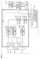
- FIG. 1 is a block diagram illustrating the configuration of a power source system of Embodiment 1 of the present invention.
- a power source system 10 of the present embodiment is provided with a power source device 100, a power storage device 300, a charge-discharge control device 400, a power supply control device 500, and a combined control ECU (Electronic Control Unit) 600.
- a power source device 100 As shown in FIG. 1 , a power source system 10 of the present embodiment is provided with a power source device 100, a power storage device 300, a charge-discharge control device 400, a power supply control device 500, and a combined control ECU (Electronic Control Unit) 600.
- ECU Electronic Control Unit
- the power source device 100 is, for example, a commercial power source and also includes a generator that uses an engine as a mechanical power source, and the like.
- a load device 200 includes various units that are driven by the supplied power.
- the power storage device 300 stores extra power from the power source device 100 and regenerative electric power generated by the load device 200 and supplies, when necessary, the power stored therein to the load device 200.
- the power storage device 300 is configured by N storage element blocks B1, B2, ..., BN that are connected in serial. Each storage element block B1, B2, ..., BN is configured by electrically connecting in serial a plurality of storage elements 301.
- An alkaline storage battery such as a nickel-hydrogen storage battery, an organic battery such as a lithium ion battery, and an electric double-layer capacitor can be used as the storage element 301.
- the number N of the storage element blocks and the number of storage elements 301 are not particularly limited.
- the power storage device 300 has an optimum operation voltage range in which battery characteristics, service life, and reliability of the power storage device 300 are not lost. This operation voltage range is determined by the minimum voltage, which is the lowest limit value, and a maximum voltage, which is the highest limit value.
- the minimum voltage of the operation voltage range is a voltage that has to end the discharge of the power storage device 300, and usually in a case where the output voltage of the power storage device 300 is below the minimum voltage, the discharge of the power storage device 300, that is, power supply from the power storage device 300 stops. However, by temporarily reducing the minimum voltage, it is possible to continue further the supply of power from the power storage device 300. In this case, the power storage device 300 is temporarily overdischarged, but battery characteristics and the like of the power storage device 300 are not adversely affected as long as the overdischarge is implemented within a range in which battery characteristics, service life, and reliability of the power storage device 300 are not lost.
- the maximum voltage of the operation voltage range is a voltage that has to end the charge of the power storage device 300, and usually in a case where the output voltage of the power storage device 300 is above the maximum voltage, the charge of the power storage device 300 stops.
- the power storage device 300 is temporarily overcharged, but battery characteristics and the like of the power storage device 300 are not adversely affected as long as the overcharge is implemented within a range in which battery characteristics, service life, and reliability of the power storage device 300 are not lost.
- the charge-discharge control device 400 controls the charge and discharge of the power storage device 300.
- the charge-discharge control device is connected to the power source unit 100, load device 200, and power storage device 300 and controls the charge of the power storage device 300 from the power source device 100 and the discharge from the power storage device 300 to the load device 200.
- the charge-discharge control device 400 discharges the lacking power from the power storage device 300 to the load device 200.
- the charge-discharge control by the charge-discharge control device 400 is usually performed so that a SOC of the power storage device 300 is within a range of about 20 to 80%.
- the control is performed so as to charge to a state with a SOC of 100% and discharge when energy is necessary in the load device.
- the power supply control device 500 controls power supply from the power storage device 300 to the load device 200 when the power source device 100 stops.
- the combined control ECU 600 is connected to the charge-discharge control device 400 and power supply control device 500 and controls the entire power source system 10.
- the power supply control device 500 of the power source system 10 of Embodiment 1 of the present invention will be described below.
- the power supply control device 500 is provided with a voltage measurement unit 501, a current measurement unit 502, a temperature measurement unit 503, a communication unit 504, and a control unit 505.
- the voltage measurement unit 501 measures a voltage value of the power storage device 300. More specifically, the voltage measurement unit 501 measures sequentially in time, with a predetermined period, voltage V0, V1, V2, ..., VN-1, VN between the terminals of respective N storage element blocks B1, B2, ..., BN of the power storage device 300. The voltage between the terminals that has been measured for each storage element block is converted from an analog signal into a digital signal and voltage data for each block and added value thereof are outputted as voltage data VD of the power storage device 300. Data output from the voltage measurement unit 501 to the control unit 505 is conducted with a predetermined period. For example, a flying capacitor method is known as a method for measuring sequentially in time the voltage between the terminals for each storage element block.
- the current measurement unit 502 measures a current value of the power storage device 300. More specifically, the current measurement unit 502 measures a charge-discharge current I of the power storage device 300 within the predetermined period by using a current sensor 302. The measured charge-discharge current is converted from an analog signal into a digital signal and outputted together with a sign C (Charge)/D (Discharge) that indicates a charge direction (+) and discharge direction (-) as current data ID. Data output from the current measurement unit 502 to the control unit 505 is also conducted with a predetermined period, similarly to the data output from the voltage measurement unit 501.
- the current sensor 302 in this configuration is constituted by a resistance element, a current transformer, and the like.
- the temperature measurement unit 503 measures the temperature of the power storage device 300. More specifically, the temperature measurement unit 503 measures the temperature inside the power storage device 300 with a predetermined period by using a temperature sensor 303 disposed inside the power storage device 300. The measured temperature is converted from an analog signal into a digital signal and outputted with a predetermined period as temperature data T to the control unit 505.
- the communication unit 504 can perform communication between the control unit 505 and the ECU 600.
- the control unit 505 transmits the measured values such as voltage, temperature, and current of the power storage device 300, a SOC calculated by using the measured values, and failure information relating to the current sensor and the like to the ECU 600.
- the ECU 600 for example, can control the entire power source system 10 on the basis of the transmitted data.
- a communication means of the ECU 600 and communication unit 504 may be CAN and Ethernet (registered trade name). Wireless communication may be also used.
- the control unit 505 controls various units located in the power supply control device 500. For example, it performs integration of current data ID outputted from the current measurement unit 502 over a predetermined period (for example, a period of equal to or shorter than 1 day) and calculates an integrated capacity Q. In a case where a sign C/D received together with the current data ID is in the charge direction (+) during this integration, the current data ID are multiplied by a charge efficiency (a coefficient less than 1, for example, 0.8). The control unit 505 predicts and stores the residual capacity SOC by using the integrated capacity Q.
- a charge efficiency a coefficient less than 1, for example, 0.8
- the SOC is found herein by using the integrated capacity Q, as described hereinabove, but the present embodiment is not limited to this feature.
- an electromotive force Vemf by subtracting a voltage drop caused by a polarization component and internal resistance of the power storage device 300 from the load-free voltage Vo and find the SOC corresponding to this electromotive force Vemf from the electromotive force - SOC characteristic table that has been found empirically in advance.
- temperature data T outputted from the temperature measurement unit 503 as correction parameters of the electromotive force - SOC characteristic table.
- the power supply control device 500 of the present embodiment supplies power from the power storage device 300 to the load device 200 when the power source device 100 stops, the state quantity of the power storage device 300 is reset and the power supply capacity from the power storage device 300 is increased.
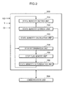
- the processing of such power supply control will be described below in grater detail. First, the configuration of the control unit 505 will be described with reference to FIG. 2 , and then the processing procedure of such power supply control will be described.
- control unit 505 controls various units located in the power supply control device 500 and has, for example, the following configuration for implementing the processing of the above-described power supply control.
- FIG. 2 shows a configuration of the control unit 505 for realizing the process of power supply control of the power supply control device 500 of Embodiment 1 of the invention.
- control unit 505 is provided with a state quantity setting unit 701, a state quantity memory unit 702, a state quantity calculation unit 703, a stop determination unit 704, a stop flag memory unit 705, and a state quantity determination unit 706.
- the state quantity setting unit 701 sets a target value of state quantity (referred to hereinbelow as "target state quantity") of the power storage device 300 that is used during charge-discharge control of the power storage device 300.
- the charge-discharge control device 400 controls charge and discharge of the power storage device 300 on the basis of the target state quantity.
- the state quantity of the power storage device 300 is, for example, a SOC indicating the state of charge of the power storage device 300, and the state quantity setting unit 701 performs resetting of the target state quantity as necessary.
- the target state quantity that is set is outputted to the charge-discharge control device 400 via the communication unit 504 and the combined control ECU 600.
- the state quantity memory unit 702 stores at least a target state quantity of the power storage device 300 when the power source device 100 operates (referred to hereinbelow as "normal target state quantity") and a target state quantity of the power storage device 300 when the power source device 100 stops (referred to hereinbelow as “abnormal target state quantity”).
- the power storage device 300 performs the charge-discharge control on the basis of the normal target state quantity (first target state quantity) when the power source device 100 operates, but performs the charge-discharge control on the basis of the abnormal target state quantity (second target state quantity), if necessary, when the power source device 100 stops. Because it is necessary to increase the power supply capacity of the power storage device 300 when the power source device 100 stops, the abnormal target state quantity is set to a value higher than the normal target state quantity.
- the state quantity calculation unit 703 can calculate the actual state quantity of the power storage device 300. In a case where a state quantity is an SOC of the power storage device 300, the state quantity calculation unit 703 calculates the SOC of the power storage device 300 by performing current integration by using current data ID from the current measurement unit 502.
- the stop determination unit 704 monitors the input of stop information relating to the power source device 100 to the control unit 505 and determines whether or not the input is made.
- the stop information relating to the power source device 100 is, for example, the stop of a commercial power supply or a main power supply. This information may also include accident information that indicates the possibility of the commercial power supply being stopped.
- the accident information may be meteorological information that predicts flood damage, fire information, and also earthquake information. It goes without saying that the accident information is not limited to these examples, and may be any accident information relating to or predicting the stoppage of the power source unit 100.
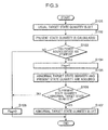
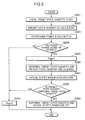
- FIG. 3 is a flowchart showing the processing procedure of power supply control of the power supply control device 500 of Embodiment 1 of the invention.
- the state quantity setting unit 701 of the control unit 505 sets the normal target state quantity of the power storage device 300 as the target state quantity during normal operation in which the power source device 100 can supply power (step S101).
- the normal target state quantity of the power storage device 300 is stored in advance in the state quantity memory unit 702, and the state quantity setting unit 701 acquires the normal target state quantity from the state quantity memory unit 702.
- the normal target state quantity that has been set is outputted via the communication unit 504 to the combined control ECU 600.
- the combined control ECU 600 controls the charge-discharge control device 400 so that the charge-discharge control of the power storage device 300 is performed on the basis of the normal target state quantity.
- the state quantity calculation unit 703 calculates the present state quantity of the power storage device 300 by appropriately using the voltage data VD, current data ID, and temperature data T inputted from the voltage measurement unit 501, current measurement unit 502, and temperature measurement unit 503 (step S102).
- the stop determination unit 704 monitors the input of stop information of the power source unit 100 to the control unit 505 and starts determining whether or not the input is present (step S103).
- the stop information of the power source device 100 is acquired by the combined control unit ECU 600 and outputted to the power supply control device 500.
- the combined control ECU 600 is provided inside thereof with a stop information acquisition unit 601 that serves for acquiring stop information of the power source device 100 and acquires the stop information of the power source device 100 from the outside by using the stop information acquisition unit 601.
- the stop information of the power source device 100 is information relating to power supply interruption from the power source device 100 due to accident such as meteorological conditions, fire, and earthquake, and the stop information acquisition unit 601 acquires this information.
- the stop information acquisition unit 601 may also directly detect the stop of power supply from the power source unit 100.
- the stop determination unit 704 determines the power source device 100 has stopped (YES in step S103)
- the state quantity determination unit 706 acquires the abnormal target state quantity of the power storage device 300 from the state quantity memory unit 702 and the present state quantity of the power storage device 300 from the state quantity calculation unit 703 (step S105).
- the state quantity determination unit 706 compares (step S106) the abnormal target state quantity and the present state quantity of the power storage device 300 that have been acquired in the above-described step S105, and in a case where the present state quantity is less than the abnormal target state quantity (YES in step S106), the state quantity setting unit 701 sets the abnormal target state quantity of the power storage device 300 as the target state quantity (step S107).
- the abnormal target state quantity that has been set is outputted from the control unit 505 to the communication unit 504.
- the power supply control device 500 uses the communication unit 504 to output the abnormal target state quantity that has been set to the combined control ECU 600.
- the combined control ECU 600 controls the charge-discharge control device 400 on the basis of the abnormal target state quantity that has been set.
- Embodiment 1 of the invention by raising the target state quantity of the power storage device 300 when the power source device 100 stops, it is possible to increase the state of charge of the power storage device 300. Therefore, the power supply capacity of the power storage device 300 can be increased and the power necessary for the load device 200 can be continuously supplied.
- the power supply capacity of the power storage device 300 can be increased only when the power source device 100 stops. Therefore, it is not necessary to increase the capacity of the power storage device 300 in advance with consideration for power supply when the power source device 100 stops. As a result, the margin relating to the capacity of the power storage device 300 can be reduced and miniaturization of the power storage device 300 can be facilitated.
- the abnormal target state quantity of the power storage device 300 may be set in the abovementioned step S107, without comparing the abnormal target state quantity and the present state quantity of the power storage device 300 in the abovementioned step 106. Even in a case where the present state quantity of the power storage device 300 is equal to or greater than the abnormal target state quantity, the increase in the state of charge of the power storage device 300 can be rapidly started if setting is made in advance to the abnormal target state quantity.
- Embodiment 1 of the invention in a case where the stop of the power source device 100 is cancelled and power supply from the power source device 100 returns to the normal state, the target state quantity of the power storage device 300 can be again returned to the normal target state quantity.
- a program for realizing the processing of power supply control of the power supply control device 500 may be executed with a microcomputer.
- a power supply control program for realizing the state quantity setting unit 701, state quantity memory unit 702, state quantity calculation unit 703, stop determination unit 704, stop flag memory unit 705, and state quantity determination unit 706 provided in the control unit 505 shown in FIG. 2 may be installed in the microcomputer and the power supply control program may be executed with the microcomputer.
- the power supply control method of the power supply control device 500 is realized by reading the power supply control program with the microcomputer and executing the program. It is also possible to install the power supply control program on a memory unit of the microcomputer and execute the power supply control program with a processing unit (Central Processing Unit: CPU) of the microcomputer. By executing the power supply control program with the processing unit of the microcomputer, it is possible to realize the state quantity setting unit 701, state quantity calculation unit 703, stop determination unit 704, and state quantity determination unit 706 and provide the state quantity memory unit 702 and stop flag memory unit 705 in the memory unit of the microcomputer.
- CPU Central Processing Unit
- the functions of the control unit 505 may be also imparted to the charge-discharge control device 400.
- the above-described power supply control program may be installed in the microcomputer that constitutes the charge-discharge control device 400 and this program may be executed. It goes without saying that the functions of the charge-discharge control device 400 may be also provided to the control unit 505. Moreover, the functions of the control unit 505 may be imparted to the load device 200 or combined control ECU 600.
- the power supply control device 500 is provided only with limited number of functions such as functions of measuring the voltage, temperature, and current of the power storage device 300.
- Embodiment 2 of the invention will be described below with reference to the drawings.
- the power supply capacity of the power storage device 300 is increased by raising the target state quantity of the power storage device 300.
- the load device 200 in addition to raising the target state quantity of the power storage device 300 as in Embodiment 1, where the load device 200 has a plurality of power consumption modes, the load device 200 is shifted to a low power consumption mode when the power source device 100 stops.
- the power required by the load device 200 when the power source device 100 stops is reduced and the state of charge of the power storage device 300 is further enhanced, thereby increasing the power supply capacity of the power storage device 300.
- the processing of power supply control of the power supply control device of the power source system of Embodiment 2 of the invention will be described below.
- the power source system of the present embodiment essentially can be realized by the same configuration as that of the power source system shown in FIG. 1 .
- the configuration provided to a control unit 505 to realize the processing of power supply control of a power supply control device 500 of the present embodiment is different.
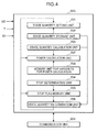
- FIG. 4 shows the configuration of the control unit 505 of the present embodiment.
- the control unit 505 of the present embodiment is provided with a state quantity setting unit 701, a state quantity memory unit 702, a state quantity calculation unit 703, a stop determination unit 704, a stop flag memory unit 705, a state quantity determination unit 706, a power calculation unit 707, and a memory unit 708 for variables for power calculation.
- the state quantity setting unit 701, state quantity memory unit 702, state quantity calculation unit 703, stop determination unit 704, stop flag memory unit 705, and state quantity determination unit 706 have the same configuration as in Embodiment 1 and will not be explained herein.
- the power calculation unit 707 calculates outputable power that can be presently outputted by the power storage device 300 by using the present state quantity of the power storage device 300 that is calculated by the state quantity calculation unit 703.
- the state quantity calculation unit 703 calculates a present open voltage of the power storage device 300 in addition to the above-described SOC.
- the open voltage is calculated by subtracting a polarization voltage and a voltage drop caused by the internal resistance of the power storage device 300 from voltage data VD from the voltage measurement unit 501.
- the power calculation unit 707 can calculate the present outputable power (power supply capacity) of the power storage device 300, for example, by the above-described Equation (1), by using the open voltage of the power storage device 300.
- the memory unit 708 for variables for power calculation stores variables that are used to determine the power actually outputted to the load device 200, from among the outputable power of the power storage device 300, to match a plurality of power consumption modes of the load device 200. For example, in a case where the load device 200 has been shifted to a low power consumption mode, variables (parameters) are used to make the output power of the power storage device 300 a part of the outputable power at the point of time of this shift.
- variable value is set, for example, to "0.25" and the load device 200 is shifted to a low power consumption mode
- the outputable power of the power storage device 300 at the point of time of this shift is multiplied by "0.25", and the actual output power of the power storage device 300 is reduced to one fourth of the outputable power.
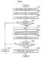
- FIG. 5 is a flowchart illustrating the processing procedure of power supply control of the power supply control device 500 of Embodiment 2 of the invention.
- the state quantity setting unit 701 of the control unit 505 sets a normal target state quantity of the power storage device 300 as the target state quantity during normal operation when power can be supplied from the power source device 100 (step S201).
- the normal target state quantity of the power storage device 300 is stored in advance in the state quantity memory unit 702, and the state quantity setting unit 701 acquires the normal target state quantity from the state quantity memory unit 702.
- the normal target state quantity that has been set is outputted to a combined control ECU 600 via a communication unit 504.
- the combined control ECU 600 controls the charge-discharge control device 400 so that charge-discharge control of the power storage device 300 is performed on the basis of this normal target state quantity.
- the state quantity calculation unit 703 then calculates the present state quantity of the power storage device 300 by appropriately using the voltage data VD, current data ID, and temperature data T inputted from a voltage measurement unit 501, a current measurement unit 502, and a temperature measurement unit 503 (step S202).
- the power calculation unit 707 then calculates the present outputable power of the power storage device 300 (step S203).
- the stop determination unit 704 then monitors the input of stop information of the power source device 100 to the control unit 505 and starts determining whether the input is present (step S204).
- the stop determination unit 704 determines that the power source device 100 has stopped (YES in step S204)
- the state quantity determination unit 706 acquires the abnormal target state quantity of the power storage device 300 from the state quantity memory unit 702 and the present state quantity of the power storage device 300 from the state quantity calculation unit 703 (step S206).
- the power calculation unit 707 acquires a predetermined variable from the memory unit 708 for variables for output calculation, which stores variables for output calculation, and calculates the power that is actually outputted to the load device 200 when the load device 200 is shifted to a low power consumption mode by using the acquired predetermined variable (step S207).
- the state quantity determination unit 706 compares (step S208) the abnormal target state quantity and the present state quantity of the power storage device 300 that have been acquired in the above-described step S206, and in a case where the present state quantity is less than the abnormal target state quantity (YES in step S208), the state quantity setting unit 701 sets the abnormal target state quantity of the power storage device 300 as the target state quantity and also sets a power that will be actually outputted by the power storage device 300 (step S209).
- the abnormal target state quantity and actual output power that have been set are outputted from the control unit 505 to the communication unit 504.
- the power supply control device 500 uses the communication unit 504 to output the abnormal target state quantity and actual output power that have been set to the combined control ECU 600.
- the combined control ECU 600 controls the charge-discharge control device 400 on the basis of the abnormal target state quantity and actual output power that have been set.
- Embodiment 2 of the invention by raising the target state quantity of the power storage device 300 when the power source device 100 stops, it is possible to increase the state of charge of the power storage device 300. Therefore, the power supply capacity of the power storage device 300 can be increased and the power necessary for the load device 200 can be continuously supplied.
- the power supply capacity of the power storage device 300 can be increased only when the power source device 100 stops. Therefore, it is not necessary to increase the capacity of the power storage device 300 in advance with consideration for power supply when the power source device 100 stops. As a result, the margin relating to the capacity of the power storage device 300 can be reduced and miniaturization of the power storage device 300 can be facilitated.
- Embodiment 2 of the invention when the power source device 100 stops, the load device 200 is shifted to a low power consumption mode, and the power that is actually outputted by the power storage device 300 to the load device 200 is decreased. Therefore, the state of charge of the power storage device 300 can be further increased and power supply capacity of the power storage device 300 can be raised.
- Embodiment 2 of the invention in a case where the stop of the power source device 100 is cancelled and power supply from the power source device 100 returns to the normal state, the target state quantity of the power storage device 300 can be again returned to the normal target state quantity.
- a program for realizing the processing of power supply control of the power supply control device 500 may be executed with a microcomputer.
- a power supply control program for realizing the state quantity setting unit 701, state quantity memory unit 702, state quantity calculation unit 703, stop determination unit 704, stop flag memory unit 705, state quantity determination unit 706, power calculation unit 707, and memory unit 708 for variables for power calculation that are provided in the control unit 505 shown in FIG. 4 may be installed in the microcomputer and the power supply control program may be executed with the microcomputer.
- the power supply control method of the power supply control device 500 is realized by reading the power supply control program with the microcomputer and executing the program. It is also possible to install the power supply control program in a memory unit of the microcomputer and execute the power supply control program with a processing unit (CPU) of the microcomputer. By executing the power supply control program with the processing unit of the microcomputer, it is possible to realize the state quantity setting unit 701, state quantity calculation unit 703, stop determination unit 704, state quantity determination unit 706, and power calculation unit 707 and provide the state quantity memory unit 702, stop flag memory unit 705, and memory unit 708 for variables for power calculation in the memory unit of the microcomputer.
- control unit 505 may be also imparted to the charge-discharge control device 400 and the functions of the charge-discharge control device 400 may be also provided to the control unit 505. Moreover, the functions of the control unit 505 may be imparted to the load device 200 or combined control ECU 600.
- Embodiment 3 of the invention will be described below with reference to the drawings.
- the power supply capacity of the power storage device 300 is increased by raising the target state quantity of the power storage device 300.
- the power necessary for the load device 200 is reduced and power supply capacity of the power storage device 300 is increased by shifting the load device 200 to a low power consumption mode when the power source device 100 stops.
- Embodiment 3 of the invention in addition to raising the target state quantity of the power storage device 300 as in Embodiment 1, the power charged to the power storage device 300 when the power source device 100 stops in increased. As a result, the state of charge of the power storage device 300 is further enhanced and power supply capacity of the power storage device 300 is increased.
- the processing of power supply control of the power supply control device of the power source system of Embodiment 3 of the invention will be described below.
- the power source system of the present embodiment essentially can be realized by the same configuration as that of the power source system shown in FIG. 1 .
- the configuration provided to a control unit 505 to realize the processing of power supply control of a power supply control device 500 of the present embodiment essentially also can be realized by the same configuration as that shown in FIG. 4 .
- the functions of the power calculation unit 707 and memory unit 708 for variables for power calculation, which are shown in FIG. 4 are different from those of the above-described Embodiment 2. This difference will be described below.
- the power calculation unit 707 calculates the inputable power that can be presently charged into the power storage device 300 by using the present state quantity of the power storage device 300 that is calculated by a state quantity calculation unit 703.
- the state quantity calculation unit 703 calculates the present open voltage of the power storage device 300 in addition to the above-described SOC.
- the power calculation unit 707 can calculate the present inputable power (electric power regeneration capacity) of the power storage device 300, for example, by the above-described Equation (2), by using the open voltage of the power storage device 300.
- a memory unit 708 for variables for power calculation stores variables that are used to determine the power that is actually inputted in the power storage device 300 when the power source device 100 stops.
- the variables are used to charge the power storage device 300 with power that is greater than the present inputable capacity of the power storage device 300. More specifically, where a variable value is set, for example, to "1.5” and the power source device 100 stops, the inputable power of the power storage device 300 at the point of time of this stop is multiplied by "1.5", and the actual input power of the power storage device 300 is increased to a power that is 1.5 times the inputable power.
- FIG. 6 is a flowchart illustrating the processing procedure of power supply control of the power supply control device 500 of Embodiment 3 of the invention.
- the state quantity setting unit 701 of the control unit 505 sets a normal target state quantity of the power storage device 300 as the target state quantity during normal operation when power can be supplied from the power source device 100 (step S301).
- the normal target state quantity of the power storage device 300 is stored in advance in the state quantity memory unit 702, and the state quantity setting unit 701 acquires the normal target state quantity from the state quantity memory unit 702.
- the normal target state quantity that has been set is outputted to a combined control ECU 600 via a communication unit 504.
- the combined control ECU 600 controls the charge-discharge control device 400 so that charge-discharge control of the power storage device 300 is performed on the basis of this normal target state quantity.
- the state quantity calculation unit 703 then calculates the present state quantity of the power storage device 300 by appropriately using the voltage data VD, current data ID, and temperature data T inputted from a voltage measurement unit 501, a current measurement unit 502, and a temperature measurement unit 503 (step S302).
- the power calculation unit 707 then calculates the present outputable power of the power storage device 300 (step S303).
- the stop determination unit 704 then monitors the input of stop information of the power source device 100 to the control unit 505 and starts determining whether the input is present (step S304).
- the stop determination unit 704 determines that the power source device 100 has stopped (YES in step S304)
- the state quantity determination unit 706 acquires the abnormal target state quantity of the power storage device 300 from the state quantity memory unit 702 and the present state quantity of the power storage device 300 from the state quantity calculation unit 703 (step S306).
- the power calculation unit 707 acquires a predetermined variable from the memory unit 708 for variables for output calculation, which stores variables for output calculation, and calculates the power that is actually inputted in the power storage device 300 by using the acquired predetermined variable (step S307).
- the state quantity determination unit 706 then compares (step S308) the abnormal target state quantity and the present state quantity of the power storage device 300 that have been acquired in the above-described step S306, and in a case where the present state quantity is less than the abnormal target state quantity (YES in step S308), the state quantity setting unit 701 sets the abnormal target state quantity of the power storage device 300 as the target state quantity and also sets a power that will be actually inputted in the power storage device 300 (step S309).
- the abnormal target state quantity and actual input power that have been set are outputted from the control unit 505 to the communication unit 504.
- the power supply control device 500 uses the communication unit 504 to output the abnormal target state quantity and actual input power that have been set to the combined control ECU 600.
- the combined control ECU 600 controls the charge-discharge control device 400 on the basis of the abnormal target state quantity and actual input power that have been set.
- Embodiment 3 of the invention by raising the target state quantity of the power storage device 300 when the power source device 100 stops, it is possible to increase the state of charge of the power storage device 300. Therefore, the power supply capacity of the power storage device 300 can be increased and the power necessary for the load device 200 can be continuously supplied.
- the power supply capacity of the power storage device 300 can be increased only when the power source device 100 stops. Therefore, it is not necessary to increase the capacity of the power storage device 300 in advance with consideration for power supply when the power source device 100 stops. As a result, the margin relating to the capacity of the power storage device 300 can be reduced and miniaturization of the power storage device 300 can be facilitated.
- Embodiment 3 of the invention when the power source device 100 stops, the input power that charges the power storage device 300 is increased. As a result, the state of charge of power storage device 300 can be further increased and the power supply capacity of the power storage device 300 can be raised.
- Embodiment 3 of the invention in a case where the stop of the power source device 100 is cancelled and power supply from the power source device 100 returns to the normal state, the target state quantity of the power storage device 300 can be again returned to the normal target state quantity.
- Embodiment 3 of the invention similarly to the above-described Embodiment 2, a program for realizing the processing of power supply control of the power supply control device 500 may be executed with a microcomputer.
- the functions of the control unit 505 may be also imparted to the charge-discharge control device 400 and the functions of the charge-discharge control device 400 may be also provided to the control unit 505.
- the functions of the control unit 505 may be imparted to the load device 200 or combined control ECU 600.
- Embodiment 4 of the invention will be described below with reference to the drawings.
- the power supply capacity of the power storage device 300 is increased by raising the target state quantity of the power storage device 300.
- the power necessary for the load device 200 is reduced and power supply capacity of the power storage device 300 is increased by shifting the load device 200 to a low power consumption mode when the power source device 100 stops.
- the state of charge of the power storage device 300 is further increased and power supply capacity of the power storage device 300 is increased by increasing the power charged into the power storage device 300.
- Embodiment 4 of the invention in addition to raising the target state quantity of the power storage device 300 as in Embodiment 1, the output power of the power storage device 300 is reduced as in the above-described Embodiment 2 and the input power of the power storage device 300 is increased as in the above-described Embodiment 3.
- the processing of power supply control of the power supply control device of the power source system of Embodiment 4 of the invention will be described below.
- the power source system of the present embodiment essentially can be realized by the same configuration as that of the power source system shown in FIG. 1 .
- the configuration provided to a control unit 505 to realize the processing of power supply control of a power supply control device 500 of the present embodiment essentially also can be realized by the same configuration as that shown in FIG. 4 .
- the power calculation unit 707 and memory unit 708 for variables for power calculation that are shown in FIG. 4 are imparted with functions of both the Embodiment 2 and the Embodiment 3.
- FIG. 7 is a flowchart illustrating the processing procedure of power supply control of the power supply control device 500 of Embodiment 4 of the invention.
- the state quantity setting unit 701 of the control unit 505 sets a normal target state quantity of the power storage device 300 as the target state quantity during normal operation when power can be supplied from the power source device 100 (step S401).
- the normal target state quantity of the power storage device 300 is stored in advance in the state quantity memory unit 702, and the state quantity setting unit 701 acquires the normal target state quantity from the state quantity memory unit 702.
- the normal target state quantity that has been set is outputted to a combined control ECU 600 via a communication unit 504.
- the combined control ECU 600 controls the charge-discharge control device 400 so that charge-discharge control of the power storage device 300 is performed on the basis of this normal target state quantity.
- the state quantity calculation unit 703 then calculates the present state quantity of the power storage device 300 by appropriately using the voltage data VD, current data ID, and temperature data T inputted from a voltage measurement unit 501, a current measurement unit 502, and a temperature measurement unit 503 (step S402).
- the power calculation unit 707 then calculates the present inputable power and outputable power of the power storage device 300 (step S403).
- the stop determination unit 704 then monitors the input of stop information of the power source device 100 to the control unit 505 and starts determining whether the input is present (step S404).
- the stop determination unit 704 determines that the power source device 100 has stopped (YES in step S404)
- the state quantity determination unit 706 acquires the abnormal target state quantity of the power storage device 300 from the state quantity memory unit 702 and the present state quantity of the power storage device 300 from the state quantity calculation unit 703 (step S406).
- the power calculation unit 707 then acquires a predetermined variable from the memory unit 708 for variables for output calculation, which stores variables for output calculation, and calculates the power that is actually inputted in the power storage device 300 by using the acquired predetermined variable (step S407). Furthermore, the power calculation unit 707 also acquires a predetermined variable from the memory unit 708 for variables for output calculation, which stores variables for output calculation, and calculates the power that is actually outputted by the power storage device 300 by using the acquired predetermined variable (step S408).
- the state quantity determination unit 706 compares (step S409) the abnormal target state quantity and the present state quantity of the power storage device 300 that have been acquired in the above-described step S406, and in a case where the present state quantity is less than the abnormal target state quantity (YES in step S409), the state quantity setting unit 701 sets the abnormal target state quantity of the power storage device 300 as the target state quantity and also sets a power that will be actually inputted in the power storage device 300 and a power that will be actually outputted by the power storage device 300 (step S410).
- the abnormal target state quantity, actual input power, and actual output power that have been set are outputted from the control unit 505 to the communication unit 504.
- the power supply control device 500 uses the communication unit 504 to output the abnormal target state quantity, actual input power, and actual output power that have been set to the combined control ECU 600.
- the combined control ECU 600 controls the charge-discharge control device 400 on the basis of the abnormal target state quantity, actual input power, and actual output power that have been set.
- Embodiment 4 of the invention by raising the target state quantity of the power storage device 300 when the power source device 100 stops, it is possible to increase the state of charge of the power storage device 300. Therefore, the power supply capacity of the power storage device 300 can be increased and the power necessary for the load device 200 can be continuously supplied.
- the power supply capacity of the power storage device 300 can be increased only when the power source device 100 stops. Therefore, it is not necessary to increase the capacity of the power storage device 300 in advance with consideration for power supply when the power source device 100 stops. As a result, the margin relating to the capacity of the power storage device 300 can be reduced and miniaturization of the power storage device 300 can be facilitated.
- Embodiment 4 of the invention when the power source device 100 stops, the load device 200 is shifted to a low power consumption mode, and the power that is actually outputted by the power storage device 300 to the load device 200 is decreased. Therefore, the state of charge of the power storage device 300 can be further increased and power supply capacity of the power storage device 300 can be raised.
- Embodiment 4 of the invention when the power source device 100 stops, the input power that charges the power storage device 300 is increased. Therefore, the state of charge of the power storage device 300 can be further increased and power supply capacity of the power storage device 300 can be raised.
- Embodiment 4 of the invention in a case where the stop of the power source device 100 is cancelled and power supply from the power source device 100 returns to the normal state, the target state quantity of the power storage device 300 can be again returned to the normal target state quantity.
- Embodiment 4 of the invention similarly to the above-described Embodiments 2 and 3, a program for realizing the processing of power supply control of the power supply control device 500 may be executed with a microcomputer.
- the functions of the control unit 505 may be also imparted to the charge-discharge control device 400 and the functions of the charge-discharge control device 400 may be also provided to the control unit 505.
- the functions of the control unit 505 may be imparted to the load device 200 or combined control ECU 600.
- a power source system in which the power supply capacity of the power storage device can be increased and power necessary for the load unit can be continuously supplied by temporarily increasing the state of charge of the power source unit.
- the invention also provides a power supply control method for the power supply system, a program for executing with a computer the power supply control method for the power supply system, and a computer-readable recording medium having recorded thereon the power supply control method for the power supply system.
- a power source system includes a power source device that supplies power to a load device; a power storage device that supplies, in place of the power source device, power to the load device when the power source device stops; and a control unit that controls power supply from the power storage device to the load device, wherein the control unit has a stop determination unit that determines whether the power supply device has stopped; and a state quantity setting unit that sets a first target state quantity indicating a state of charge of the power storage device that is to be a target value when charge and discharge of the power storage device are controlled, in order to maintain the state of charge of the power storage device within a predetermined range, and the state quantity setting unit changes the first target state quantity to a second target state quantity that is to be a target value exceeding the first target state quantity when the stop determination unit determines that the power source device has stopped.
- the stop determination unit determines whether the power source device has stopped, and where the power source device is determined to have stopped, the target state quantity of the power storage device can be increased.
- charge and discharge of the power storage device are controlled on the basis of a target state quantity that exceeds that during the operation of the power source device. Therefore, the state of charge of the power storage device can be improved over that during the operation of the power source device.
- the power supply capacity of the power storage device can be increased and the power necessary for the load device can be continuously supplied, in place of the power source device.
- the stop determination unit determines whether the power source device has stopped. Therefore, the power supply capacity of the power storage device can be increased only when the power source unit stops. Thus, it is not necessary to increase the capacity of the power storage device in advance with consideration for the increase in power supply when the power source device stops, and the margin relating to the capacity of the power storage device can be reduced. As a result, miniaturization of the power storage device installed in the power source system can be facilitated.
- control unit further have a state quantity calculation unit that uses data of at least one type from among voltage data, current data, and temperature data of the power storage device to calculate a present state quantity that indicates a present state of charge of the power storage device; and a state quantity determination unit that determines whether the present state quantity of the power storage device is lower than the second target state quantity, and the state quantity setting unit changes the first target state quantity to the second target state quantity in a case where the power source device is determined to have stopped and in a case where the present state quantity of the power storage device is determined to be lower than the second target state quantity.
- the target state quantity of the power storage device can be set to the second target state quantity only when the present state quantity of the power storage device is less than the second target state quantity of the power storage device when the power source device is stopped.
- the present state quantity of the power storage device is equal to or greater than the second target state quantity, changes in the target state quantity of the power storage device that are essentially not required are not made.
- the charge-discharge control of the power storage device can be executed more efficiently.
- control unit further have an output power calculation unit that calculates an outputable power that can be outputted by the power storage device by using the present state quantity of the power storage device that is calculated by the state quantity calculation unit, and sets a power that is lower than the calculated outputable power of the power storage device as a power that is to be actually outputted from the power storage device when the stop determination unit determines that the power source device has stopped.
- the power that is actually outputted by the power storage device can be reduced when the power source device stops. Because of such a reduction, the state of charge of the power storage device can be increased and the power supply capacity of the power storage device can be raised.
- the load device preferably has a plurality of power consumption modes that include at least a normal power consumption mode and a low power consumption mode, and the power consumption mode of the load device is shifted to the low power consumption mode in a case where a power that is lower than the outputable power of the power storage device that is calculated by the power calculation unit is set as a power that is to be actually outputted from the power storage device.
- the power consumption mode of the load device can be shifted to the low power consumption mode.
- the state of charge of the power storage device can be increased and the power supply capacity of the power storage device can be raised, while the load device executes a minimum function corresponding to the low power consumption mode thereof.
- control unit further have an input power calculation unit that calculates an inputable power that can be inputted in the power storage device in order to charge the power storage device, by using the present state quantity of the power storage device that is calculated by the state quantity calculation unit, and sets a power that is higher than the calculated inputable power of the power storage device as a power that is to be actually inputted in the power storage device in a case where the stop determination unit determines that the power source device has stopped.
- an input power calculation unit that calculates an inputable power that can be inputted in the power storage device in order to charge the power storage device, by using the present state quantity of the power storage device that is calculated by the state quantity calculation unit, and sets a power that is higher than the calculated inputable power of the power storage device as a power that is to be actually inputted in the power storage device in a case where the stop determination unit determines that the power source device has stopped.
- the input power that charges the power storage device can be increased when the power source device stops. Because of such an increase, the state of charge of the power storage device can be further increased and the power supply capacity of the power storage device can be raised.
- a power supply control method for a power source system is a power supply control method for a power source system provided with a power storage device that supplies, in place of a power source device, power to a load device when the power source device that supplies power to the load device stops, including: a first step of setting a first target state quantity indicating a state of charge of the power storage device that is to be a target value when charge and discharge of the power storage device are controlled, in order to maintain the state of charge of the power storage device within a predetermined range; and a second step of controlling charge and discharge of the power storage device on the basis of the first target state quantity of the power storage device that is set in the first step, wherein the first step includes a step of changing the first target state quantity to a second target state quantity that is to be a target value exceeding the first target state quantity when the power source device stops.
- the target state quantity of the power storage device can be increased in a case where the power source device has stopped.
- charge and discharge of the power storage device are controlled on the basis of a target state quantity that exceeds that during the operation of the power source device. Therefore, the state of charge of the power storage device can be improved over that during the operation of the power source device.
- the power supply capacity of the power storage device can be increased and the power necessary for the load device can be continuously supplied, in place of the power source device.
- the power supply capacity of the power storage device can be increased only when the power source unit stops. Therefore, it is not necessary to increase the capacity of the power storage device in advance with consideration for the increase in power supply when the power source device stops, and the margin relating to the capacity of the power storage device can be reduced. As a result, miniaturization of the power storage device installed in the power source system can be facilitated.
- a power supply control program for a power source system is a power supply control program for a power source system provided with a power storage device that supplies, in place of a power source device, power to a load device when the power source device that supplies power to the load device stops, the power supply control program causing a computer to function as: a stop determination unit that determines whether the power supply device has stopped; and a state quantity setting unit that sets a first target state quantity indicating a state of charge of the power storage device that is to be a target value when charge and discharge of the power storage device are controlled, in order to maintain the state of charge of the power storage device within a predetermined range, wherein the state quantity setting unit changes the first target state quantity to a second target state quantity that is to be a target value exceeding the first target state quantity when the stop determination unit determines that the power source device has stopped.
- the stop determination unit determines whether the power source device has stopped, and where the power source device is determined to have stopped, the target state quantity of the power storage device can be increased.
- charge and discharge of the power storage device are controlled on the basis of a target state quantity that exceeds that during the operation of the power source device. Therefore, the state of charge of the power storage device can be improved over that during the operation of the power source device.
- the power supply capacity of the power storage device can be increased and the power necessary for the load device can be continuously supplied, in place of the power source device.
- the stop determination unit determines whether the power source device has stopped. Therefore, the power supply capacity of the power storage device can be increased only when the power source unit stops. Thus, it is not necessary to increase the capacity of the power storage device in advance with consideration for the increase in power supply when the power source device stops, and the margin relating to the capacity of the power storage device can be reduced. As a result, miniaturization of the power storage device installed in the power source system can be facilitated.
- a computer-readable recording medium that has recorded thereon a power supply control program for a power source system is a computer-readable recording medium that has recorded thereon a power supply control program for a power source system provided with a power storage device that supplies, in place of a power source device, power to a load device when the power source device that supplies power to the load device stops, wherein the power supply control program causes a computer to function as: a stop determination unit that determines whether the power supply device has stopped; and a state quantity setting unit that sets a first target state quantity indicating a state of charge of the power storage device that is to be a target value when charge and discharge of the power storage device are controlled, in order to maintain the state of charge of the power storage device within a predetermined range, the state quantity setting unit changing the first target state quantity to a second target state quantity that is to be a target value exceeding the first target state quantity when the stop determination unit determines that the power source device has stopped.
- the stop determination unit determines whether the power source device has stopped, and where the power source device is determined to have stopped, the target state quantity of the power storage device can be increased.
- charge and discharge of the power storage device are controlled on the basis of a target state quantity that exceeds that during the operation of the power source device. Therefore, the state of charge of the power storage device can be improved over that during the operation of the power source device.
- the power supply capacity of the power storage device can be increased and the power necessary for the load device can be continuously supplied, in place of the power source device.
- the stop determination unit determines whether the power source device has stopped. Therefore, the power supply capacity of the power storage device can be increased only when the power source unit stops. Thus, it is not necessary to increase the capacity of the power storage device in advance with consideration for the increase in power supply when the power source device stops, and the margin relating to the capacity of the power storage device can be reduced. As a result, miniaturization of the power storage device installed in the power source system can be facilitated.
- the power source system, power supply control method for the power source system, power supply control program for the power control system, and computer-readable recording medium with the power supply control program for the power source system recorded thereon are effective for power sources and devices having a backup power source function and have industrial applicability.
Landscapes
- Engineering & Computer Science (AREA)
- Power Engineering (AREA)
- Business, Economics & Management (AREA)
- Emergency Management (AREA)
- Manufacturing & Machinery (AREA)
- Chemical & Material Sciences (AREA)
- Chemical Kinetics & Catalysis (AREA)
- Electrochemistry (AREA)
- General Chemical & Material Sciences (AREA)
- Charge And Discharge Circuits For Batteries Or The Like (AREA)
- Stand-By Power Supply Arrangements (AREA)
- Secondary Cells (AREA)
Applications Claiming Priority (2)
| Application Number | Priority Date | Filing Date | Title |
|---|---|---|---|
| JP2007017830A JP5132158B2 (ja) | 2007-01-29 | 2007-01-29 | 電源システム、電源システムの電力供給制御方法及びその電力供給制御プログラム |
| PCT/JP2008/050209 WO2008093525A1 (fr) | 2007-01-29 | 2008-01-10 | Système de source de puissance, procédé de commande de source de puissance pour le système de source de puissance, programme de commande d'alimentation électrique pour le système de source de puissance, et support d'enregistrement lisible par ordinateur avec programme de commande d'alimentation é |
Publications (2)
| Publication Number | Publication Date |
|---|---|
| EP2107663A1 true EP2107663A1 (fr) | 2009-10-07 |
| EP2107663A4 EP2107663A4 (fr) | 2011-09-14 |
Family
ID=39673839
Family Applications (1)
| Application Number | Title | Priority Date | Filing Date |
|---|---|---|---|
| EP08703073A Withdrawn EP2107663A4 (fr) | 2007-01-29 | 2008-01-10 | Système de source de puissance, procédé de commande de source de puissance pour le système de source de puissance, programme de commande d'alimentation électrique pour le système de source de puissance, et support d'enregistrement lisible par ordinateur avec programme de commande d'alimentation é |
Country Status (5)
| Country | Link |
|---|---|
| US (1) | US8159186B2 (fr) |
| EP (1) | EP2107663A4 (fr) |
| JP (1) | JP5132158B2 (fr) |
| CN (1) | CN101595620B (fr) |
| WO (1) | WO2008093525A1 (fr) |
Cited By (2)
| Publication number | Priority date | Publication date | Assignee | Title |
|---|---|---|---|---|
| EP2748729A4 (fr) * | 2011-08-25 | 2015-06-10 | Volt4 Pty Ltd | Procédé et contrôleur pour commander la fourniture d'électricité d'une batterie vers une charge |
| CN106357009A (zh) * | 2016-10-31 | 2017-01-25 | 国网江苏省电力公司电力科学研究院 | 一种用于电力设备状态检测传感器的自取能电源装置 |
Families Citing this family (34)
| Publication number | Priority date | Publication date | Assignee | Title |
|---|---|---|---|---|
| DE102007009297A1 (de) * | 2007-02-19 | 2008-08-21 | Picanol N.V. | Verfahren zum Ansteuern von Antriebsmotoren und Steuerung für Antriebsmotoren einer Webmaschine |
| US8237447B2 (en) * | 2007-05-11 | 2012-08-07 | Panasonic Ev Energy Co., Ltd. | Apparatus for detecting state of storage device |
| JP5173276B2 (ja) * | 2007-06-22 | 2013-04-03 | パナソニック株式会社 | 電源システム、電源システムの電力供給制御方法及びその電力供給制御プログラム |
| BRPI1008178A8 (pt) | 2009-02-09 | 2017-09-19 | Xtreme Power Inc | Descarga de baterias |
| US8433454B2 (en) * | 2010-01-26 | 2013-04-30 | Acumentrics Corporation | Method and system for modifying operation according to detected orientation |
| CN102472802A (zh) * | 2010-03-26 | 2012-05-23 | 松下电器产业株式会社 | 充电状态检测电路、电池电源装置以及电池信息监视装置 |
| JP4957827B2 (ja) * | 2010-04-14 | 2012-06-20 | トヨタ自動車株式会社 | 電源システムおよびそれを搭載する車両 |
| US8471520B2 (en) | 2010-05-04 | 2013-06-25 | Xtreme Power Inc. | Managing renewable power generation |
| EP2571132A1 (fr) * | 2010-05-10 | 2013-03-20 | Panasonic Corporation | Dispositif de commande, système de stockage de charge, procédé de commande et programme informatique |
| US8219333B2 (en) * | 2010-06-29 | 2012-07-10 | O2Micro, Inc | Battery management systems for protecting batteries from fault conditions |
| JP5184718B2 (ja) * | 2010-07-28 | 2013-04-17 | パナソニック株式会社 | 電力供給システム、電力供給システムの制御装置、電力供給システムの運転方法、及び電力供給システムの制御方法 |
| JP5539094B2 (ja) * | 2010-08-02 | 2014-07-02 | 三菱電機株式会社 | 非常用電源装置 |
| DE102010062249A1 (de) * | 2010-12-01 | 2012-06-21 | Zf Friedrichshafen Ag | Vorrichtung zur Verwendung in einem elektrischen Antriebssystem und Verfahren zum Betrieb einer solchen |
| KR101288122B1 (ko) * | 2011-01-03 | 2013-07-18 | 삼성에스디아이 주식회사 | 배터리 충전방법, 및 이를 적용한 배터리 팩 |
| JP5405534B2 (ja) * | 2011-07-20 | 2014-02-05 | 株式会社正興電機製作所 | 貯蔵電力制御装置、貯蔵電力制御方法及びプログラム |
| US9685887B2 (en) | 2012-10-12 | 2017-06-20 | Younicos Inc. | Controlling power conversion systems |
| JP6014463B2 (ja) * | 2012-11-07 | 2016-10-25 | 日立建機株式会社 | 作業車両 |
| US9368968B2 (en) | 2012-12-28 | 2016-06-14 | Younicos, Inc. | Responding to local grid events and distributed grid events |
| US9276425B2 (en) | 2012-12-28 | 2016-03-01 | Younicos Inc. | Power management systems with dynamic target state of charge |
| US8901888B1 (en) | 2013-07-16 | 2014-12-02 | Christopher V. Beckman | Batteries for optimizing output and charge balance with adjustable, exportable and addressable characteristics |
| FR3011399B1 (fr) * | 2013-09-30 | 2015-11-06 | Eads Europ Aeronautic Defence | Dispositif d'alimentation electrique d'une charge et procede associe |
| JP2015155859A (ja) * | 2014-02-21 | 2015-08-27 | ソニー株式会社 | 電池残量推定装置、電池パック、蓄電装置、電動車両および電池残量推定方法 |
| IN2014DE00843A (fr) * | 2014-03-24 | 2015-10-02 | Otis Elevator Co | |
| CN106133541B (zh) * | 2014-03-31 | 2019-06-18 | 株式会社东芝 | 备用电源系统、劣化推定装置以及劣化推定方法 |
| JP6413311B2 (ja) * | 2014-04-11 | 2018-10-31 | 株式会社村田製作所 | 蓄電装置、制御方法、制御装置、蓄電システム、電動車両および電子機器 |
| JP6413486B2 (ja) * | 2014-08-26 | 2018-10-31 | 日本電気株式会社 | 電池制御装置、電池制御方法、及び電池制御プログラム |
| WO2016042672A1 (fr) * | 2014-09-19 | 2016-03-24 | 株式会社昭電 | Appareil d'alimentation électrique hybride et système d'utilisation d'alimentation électrique hybride |
| US10354206B2 (en) * | 2014-10-02 | 2019-07-16 | Airbnb, Inc. | Determining host preferences for accommodation listings |
| CN105630123B (zh) * | 2014-11-26 | 2018-10-12 | 鸿富锦精密工业(武汉)有限公司 | 供电系统 |
| JP6220904B2 (ja) * | 2016-01-14 | 2017-10-25 | 本田技研工業株式会社 | 蓄電装置 |
| WO2018181666A1 (fr) * | 2017-03-30 | 2018-10-04 | 株式会社Gsユアサ | Dispositif d'alimentation, serveur et système de gestion de dispositif d'alimentation |
| JP6557393B1 (ja) * | 2018-10-31 | 2019-08-07 | 日本たばこ産業株式会社 | エアロゾル吸引器用の電源ユニットと、その制御方法及び制御プログラム |
| US10723235B1 (en) * | 2019-08-30 | 2020-07-28 | Kitty Hawk Corporation | Flexible battery system for a vehicle |
| US11322930B1 (en) * | 2020-10-20 | 2022-05-03 | Lear Corporation | Electrical system including a power distribution circuit |
Citations (1)
| Publication number | Priority date | Publication date | Assignee | Title |
|---|---|---|---|---|
| EP2096734A1 (fr) * | 2006-12-19 | 2009-09-02 | Panasonic Corporation | Système d'alimentation électrique, procédé de commande d'alimentation électrique du système d'alimentation électrique, programme de commande d'alimentation électrique du système d'alimentation électrique et support d'enregistrement lisible par ordinateur ayant un programme de |
Family Cites Families (8)
| Publication number | Priority date | Publication date | Assignee | Title |
|---|---|---|---|---|
| JP3261901B2 (ja) * | 1994-12-19 | 2002-03-04 | 三菱電機株式会社 | エレベーターの非常時運転装置 |
| JP3594283B2 (ja) * | 1998-01-09 | 2004-11-24 | 東芝エレベータ株式会社 | エレベータの停電時救出運転装置 |
| US6396243B2 (en) * | 2000-03-22 | 2002-05-28 | International Business Machines Corporation | Power unit and power source switching apparatus for a computer |
| JP2002369407A (ja) * | 2001-06-06 | 2002-12-20 | Hitachi Ltd | ピークカット機能付きバックアップ電源 |
| JP3733932B2 (ja) * | 2002-08-07 | 2006-01-11 | サクサ株式会社 | エネルギー蓄積装置 |
| JP2004357377A (ja) * | 2003-05-28 | 2004-12-16 | Osaka Gas Co Ltd | 分散型発電システム |
| JP2005341686A (ja) * | 2004-05-26 | 2005-12-08 | Nisshinbo Ind Inc | 瞬時電圧低下補償装置 |
| JP4745879B2 (ja) * | 2006-04-06 | 2011-08-10 | 日立ビークルエナジー株式会社 | ハイブリッド車両制御システム、ハイブリッド車両制御方法及び車両用蓄電池制御システム |
-
2007
- 2007-01-29 JP JP2007017830A patent/JP5132158B2/ja not_active Expired - Fee Related
-
2008
- 2008-01-10 CN CN2008800026803A patent/CN101595620B/zh not_active Expired - Fee Related
- 2008-01-10 US US12/524,068 patent/US8159186B2/en not_active Expired - Fee Related
- 2008-01-10 WO PCT/JP2008/050209 patent/WO2008093525A1/fr active Application Filing
- 2008-01-10 EP EP08703073A patent/EP2107663A4/fr not_active Withdrawn
Patent Citations (1)
| Publication number | Priority date | Publication date | Assignee | Title |
|---|---|---|---|---|
| EP2096734A1 (fr) * | 2006-12-19 | 2009-09-02 | Panasonic Corporation | Système d'alimentation électrique, procédé de commande d'alimentation électrique du système d'alimentation électrique, programme de commande d'alimentation électrique du système d'alimentation électrique et support d'enregistrement lisible par ordinateur ayant un programme de |
Non-Patent Citations (1)
| Title |
|---|
| See also references of WO2008093525A1 * |
Cited By (3)
| Publication number | Priority date | Publication date | Assignee | Title |
|---|---|---|---|---|
| EP2748729A4 (fr) * | 2011-08-25 | 2015-06-10 | Volt4 Pty Ltd | Procédé et contrôleur pour commander la fourniture d'électricité d'une batterie vers une charge |
| CN106357009A (zh) * | 2016-10-31 | 2017-01-25 | 国网江苏省电力公司电力科学研究院 | 一种用于电力设备状态检测传感器的自取能电源装置 |
| CN106357009B (zh) * | 2016-10-31 | 2018-10-12 | 国网江苏省电力公司电力科学研究院 | 一种用于电力设备状态检测传感器的自取能电源装置 |
Also Published As
| Publication number | Publication date |
|---|---|
| JP5132158B2 (ja) | 2013-01-30 |
| JP2008187800A (ja) | 2008-08-14 |
| US8159186B2 (en) | 2012-04-17 |
| US20100026244A1 (en) | 2010-02-04 |
| EP2107663A4 (fr) | 2011-09-14 |
| CN101595620A (zh) | 2009-12-02 |
| WO2008093525A1 (fr) | 2008-08-07 |
| CN101595620B (zh) | 2012-06-06 |
Similar Documents
| Publication | Publication Date | Title |
|---|---|---|
| EP2107663A1 (fr) | Système de source de puissance, procédé de commande de source de puissance pour le système de source de puissance, programme de commande d'alimentation électrique pour le système de source de puissance, et support d'enregistrement lisible par ordinateur avec programme de commande d'alimentation é | |
| EP2096734A1 (fr) | Système d'alimentation électrique, procédé de commande d'alimentation électrique du système d'alimentation électrique, programme de commande d'alimentation électrique du système d'alimentation électrique et support d'enregistrement lisible par ordinateur ayant un programme de | |
| JP5173276B2 (ja) | 電源システム、電源システムの電力供給制御方法及びその電力供給制御プログラム | |
| JP4773848B2 (ja) | 二次電池の充放電制御システム、電池制御装置、およびプログラム | |
| EP2083494A1 (fr) | Dispositif de détection d'anomalie pour élément de mémorisation, procédé de détection d'anomalie pour élément de mémorisation, programme de détection d'anomalie pour élément de mémorisation, et support d'enregistrement pouvant | |
| EP3410558A1 (fr) | Dispositif de commande de batterie | |
| WO2009104348A1 (fr) | Circuit de commande de charge, dispositif de charge muni de celui-ci et bloc-batterie | |
| WO2010047046A1 (fr) | Circuit de diagnostic de panne, dispositif d’alimentation en énergie et procédé de diagnostic de panne | |
| EP2088445A1 (fr) | Dispositif de détection de panne d'accumulateur, procédé de détection de panne d'accumulateur, programme de détection de panne d'accumulateur et support d'enregistrement lisible par ordinateur contenant le programme de détection de panne d'accumulateur | |
| EP1801947A2 (fr) | Procédé de compensation de l'état de charge d'une batterie et système de gestion de batterie | |
| US10873201B2 (en) | Battery management apparatus and method for protecting a lithium iron phosphate cell from over-voltage using the same | |
| JP2006208377A (ja) | バッテリパックのモニタリング装置及びその方法 | |
| KR20130031858A (ko) | 배터리 충전 장치 및 배터리 충전 방법 | |
| JP2008141846A (ja) | 充電状態予測プログラム、架線レス交通システム及びその充電方法 | |
| CN103531861A (zh) | 蓄电池和机动车 | |
| JP2010200574A (ja) | 自己診断回路、及び電源装置 | |
| JP2010273519A (ja) | 充放電制御方法 | |
| JP2005160233A (ja) | 組電池及び電池パック | |
| JP2019507578A (ja) | 蓄電池放電のための制御装置および蓄電池を放電する方法 | |
| JP2019512201A (ja) | 蓄電池充電のための制御装置および蓄電池を充電する方法 | |
| JP2021535721A (ja) | バッテリー管理方法、バッテリー装置、およびバッテリーを含む自動車 | |
| CN116707082A (zh) | 一种锂电池放电控制方法、系统、终端及存储介质 | |
| JP4206348B2 (ja) | 電池パック及び電動工具 | |
| JP4960656B2 (ja) | 電池制御装置およびプログラム | |
| KR102020044B1 (ko) | 배터리 충전 시스템 및 이를 이용한 배터리 모듈의 최대용량 충전 제어방법 |
Legal Events
| Date | Code | Title | Description |
|---|---|---|---|
| PUAI | Public reference made under article 153(3) epc to a published international application that has entered the european phase |
Free format text: ORIGINAL CODE: 0009012 |
|
| 17P | Request for examination filed |
Effective date: 20090721 |
|
| AK | Designated contracting states |
Kind code of ref document: A1 Designated state(s): AT BE BG CH CY CZ DE DK EE ES FI FR GB GR HR HU IE IS IT LI LT LU LV MC MT NL NO PL PT RO SE SI SK TR |
|
| DAX | Request for extension of the european patent (deleted) | ||
| A4 | Supplementary search report drawn up and despatched |
Effective date: 20110817 |
|
| RIC1 | Information provided on ipc code assigned before grant |
Ipc: B66B 1/00 20060101ALI20110810BHEP Ipc: H02J 9/06 20060101ALI20110810BHEP Ipc: H02J 7/00 20060101ALI20110810BHEP Ipc: H02J 9/00 20060101ALI20110810BHEP Ipc: H01M 10/44 20060101ALI20110810BHEP Ipc: H02J 7/34 20060101AFI20110810BHEP |
|
| 17Q | First examination report despatched |
Effective date: 20120725 |
|
| STAA | Information on the status of an ep patent application or granted ep patent |
Free format text: STATUS: THE APPLICATION IS DEEMED TO BE WITHDRAWN |
|
| 18D | Application deemed to be withdrawn |
Effective date: 20130628 |