EP2107295A2 - Leuchtenvorrichtung mit LEDs - Google Patents
Leuchtenvorrichtung mit LEDs Download PDFInfo
- Publication number
- EP2107295A2 EP2107295A2 EP09004657A EP09004657A EP2107295A2 EP 2107295 A2 EP2107295 A2 EP 2107295A2 EP 09004657 A EP09004657 A EP 09004657A EP 09004657 A EP09004657 A EP 09004657A EP 2107295 A2 EP2107295 A2 EP 2107295A2
- Authority
- EP
- European Patent Office
- Prior art keywords
- led
- illuminant carrier
- control electronics
- designed
- temperature
- Prior art date
- Legal status (The legal status is an assumption and is not a legal conclusion. Google has not performed a legal analysis and makes no representation as to the accuracy of the status listed.)
- Granted
Links
Images


Classifications
-
- H—ELECTRICITY
- H05—ELECTRIC TECHNIQUES NOT OTHERWISE PROVIDED FOR
- H05B—ELECTRIC HEATING; ELECTRIC LIGHT SOURCES NOT OTHERWISE PROVIDED FOR; CIRCUIT ARRANGEMENTS FOR ELECTRIC LIGHT SOURCES, IN GENERAL
- H05B47/00—Circuit arrangements for operating light sources in general, i.e. where the type of light source is not relevant
- H05B47/10—Controlling the light source
- H05B47/105—Controlling the light source in response to determined parameters
- H05B47/115—Controlling the light source in response to determined parameters by determining the presence or movement of objects or living beings
-
- F—MECHANICAL ENGINEERING; LIGHTING; HEATING; WEAPONS; BLASTING
- F21—LIGHTING
- F21S—NON-PORTABLE LIGHTING DEVICES; SYSTEMS THEREOF; VEHICLE LIGHTING DEVICES SPECIALLY ADAPTED FOR VEHICLE EXTERIORS
- F21S8/00—Lighting devices intended for fixed installation
- F21S8/08—Lighting devices intended for fixed installation with a standard
-
- F—MECHANICAL ENGINEERING; LIGHTING; HEATING; WEAPONS; BLASTING
- F21—LIGHTING
- F21V—FUNCTIONAL FEATURES OR DETAILS OF LIGHTING DEVICES OR SYSTEMS THEREOF; STRUCTURAL COMBINATIONS OF LIGHTING DEVICES WITH OTHER ARTICLES, NOT OTHERWISE PROVIDED FOR
- F21V21/00—Supporting, suspending, or attaching arrangements for lighting devices; Hand grips
- F21V21/14—Adjustable mountings
- F21V21/26—Pivoted arms
-
- F—MECHANICAL ENGINEERING; LIGHTING; HEATING; WEAPONS; BLASTING
- F21—LIGHTING
- F21V—FUNCTIONAL FEATURES OR DETAILS OF LIGHTING DEVICES OR SYSTEMS THEREOF; STRUCTURAL COMBINATIONS OF LIGHTING DEVICES WITH OTHER ARTICLES, NOT OTHERWISE PROVIDED FOR
- F21V21/00—Supporting, suspending, or attaching arrangements for lighting devices; Hand grips
- F21V21/14—Adjustable mountings
- F21V21/30—Pivoted housings or frames
-
- F—MECHANICAL ENGINEERING; LIGHTING; HEATING; WEAPONS; BLASTING
- F21—LIGHTING
- F21V—FUNCTIONAL FEATURES OR DETAILS OF LIGHTING DEVICES OR SYSTEMS THEREOF; STRUCTURAL COMBINATIONS OF LIGHTING DEVICES WITH OTHER ARTICLES, NOT OTHERWISE PROVIDED FOR
- F21V23/00—Arrangement of electric circuit elements in or on lighting devices
- F21V23/04—Arrangement of electric circuit elements in or on lighting devices the elements being switches
- F21V23/0442—Arrangement of electric circuit elements in or on lighting devices the elements being switches activated by means of a sensor, e.g. motion or photodetectors
- F21V23/0457—Arrangement of electric circuit elements in or on lighting devices the elements being switches activated by means of a sensor, e.g. motion or photodetectors the sensor sensing the operating status of the lighting device, e.g. to detect failure of a light source or to provide feedback to the device
-
- F—MECHANICAL ENGINEERING; LIGHTING; HEATING; WEAPONS; BLASTING
- F21—LIGHTING
- F21V—FUNCTIONAL FEATURES OR DETAILS OF LIGHTING DEVICES OR SYSTEMS THEREOF; STRUCTURAL COMBINATIONS OF LIGHTING DEVICES WITH OTHER ARTICLES, NOT OTHERWISE PROVIDED FOR
- F21V23/00—Arrangement of electric circuit elements in or on lighting devices
- F21V23/04—Arrangement of electric circuit elements in or on lighting devices the elements being switches
- F21V23/0442—Arrangement of electric circuit elements in or on lighting devices the elements being switches activated by means of a sensor, e.g. motion or photodetectors
- F21V23/0464—Arrangement of electric circuit elements in or on lighting devices the elements being switches activated by means of a sensor, e.g. motion or photodetectors the sensor sensing the level of ambient illumination, e.g. dawn or dusk sensors
-
- F—MECHANICAL ENGINEERING; LIGHTING; HEATING; WEAPONS; BLASTING
- F21—LIGHTING
- F21V—FUNCTIONAL FEATURES OR DETAILS OF LIGHTING DEVICES OR SYSTEMS THEREOF; STRUCTURAL COMBINATIONS OF LIGHTING DEVICES WITH OTHER ARTICLES, NOT OTHERWISE PROVIDED FOR
- F21V23/00—Arrangement of electric circuit elements in or on lighting devices
- F21V23/04—Arrangement of electric circuit elements in or on lighting devices the elements being switches
- F21V23/0442—Arrangement of electric circuit elements in or on lighting devices the elements being switches activated by means of a sensor, e.g. motion or photodetectors
- F21V23/0471—Arrangement of electric circuit elements in or on lighting devices the elements being switches activated by means of a sensor, e.g. motion or photodetectors the sensor detecting the proximity, the presence or the movement of an object or a person
-
- H—ELECTRICITY
- H05—ELECTRIC TECHNIQUES NOT OTHERWISE PROVIDED FOR
- H05B—ELECTRIC HEATING; ELECTRIC LIGHT SOURCES NOT OTHERWISE PROVIDED FOR; CIRCUIT ARRANGEMENTS FOR ELECTRIC LIGHT SOURCES, IN GENERAL
- H05B45/00—Circuit arrangements for operating light-emitting diodes [LED]
- H05B45/10—Controlling the intensity of the light
- H05B45/18—Controlling the intensity of the light using temperature feedback
-
- H—ELECTRICITY
- H05—ELECTRIC TECHNIQUES NOT OTHERWISE PROVIDED FOR
- H05B—ELECTRIC HEATING; ELECTRIC LIGHT SOURCES NOT OTHERWISE PROVIDED FOR; CIRCUIT ARRANGEMENTS FOR ELECTRIC LIGHT SOURCES, IN GENERAL
- H05B47/00—Circuit arrangements for operating light sources in general, i.e. where the type of light source is not relevant
- H05B47/10—Controlling the light source
- H05B47/105—Controlling the light source in response to determined parameters
- H05B47/11—Controlling the light source in response to determined parameters by determining the brightness or colour temperature of ambient light
-
- F—MECHANICAL ENGINEERING; LIGHTING; HEATING; WEAPONS; BLASTING
- F21—LIGHTING
- F21S—NON-PORTABLE LIGHTING DEVICES; SYSTEMS THEREOF; VEHICLE LIGHTING DEVICES SPECIALLY ADAPTED FOR VEHICLE EXTERIORS
- F21S8/00—Lighting devices intended for fixed installation
- F21S8/03—Lighting devices intended for fixed installation of surface-mounted type
- F21S8/033—Lighting devices intended for fixed installation of surface-mounted type the surface being a wall or like vertical structure, e.g. building facade
-
- F—MECHANICAL ENGINEERING; LIGHTING; HEATING; WEAPONS; BLASTING
- F21—LIGHTING
- F21V—FUNCTIONAL FEATURES OR DETAILS OF LIGHTING DEVICES OR SYSTEMS THEREOF; STRUCTURAL COMBINATIONS OF LIGHTING DEVICES WITH OTHER ARTICLES, NOT OTHERWISE PROVIDED FOR
- F21V29/00—Protecting lighting devices from thermal damage; Cooling or heating arrangements specially adapted for lighting devices or systems
- F21V29/50—Cooling arrangements
- F21V29/502—Cooling arrangements characterised by the adaptation for cooling of specific components
- F21V29/507—Cooling arrangements characterised by the adaptation for cooling of specific components of means for protecting lighting devices from damage, e.g. housings
-
- F—MECHANICAL ENGINEERING; LIGHTING; HEATING; WEAPONS; BLASTING
- F21—LIGHTING
- F21V—FUNCTIONAL FEATURES OR DETAILS OF LIGHTING DEVICES OR SYSTEMS THEREOF; STRUCTURAL COMBINATIONS OF LIGHTING DEVICES WITH OTHER ARTICLES, NOT OTHERWISE PROVIDED FOR
- F21V29/00—Protecting lighting devices from thermal damage; Cooling or heating arrangements specially adapted for lighting devices or systems
- F21V29/50—Cooling arrangements
- F21V29/70—Cooling arrangements characterised by passive heat-dissipating elements, e.g. heat-sinks
- F21V29/74—Cooling arrangements characterised by passive heat-dissipating elements, e.g. heat-sinks with fins or blades
- F21V29/76—Cooling arrangements characterised by passive heat-dissipating elements, e.g. heat-sinks with fins or blades with essentially identical parallel planar fins or blades, e.g. with comb-like cross-section
- F21V29/763—Cooling arrangements characterised by passive heat-dissipating elements, e.g. heat-sinks with fins or blades with essentially identical parallel planar fins or blades, e.g. with comb-like cross-section the planes containing the fins or blades having the direction of the light emitting axis
-
- F—MECHANICAL ENGINEERING; LIGHTING; HEATING; WEAPONS; BLASTING
- F21—LIGHTING
- F21W—INDEXING SCHEME ASSOCIATED WITH SUBCLASSES F21K, F21L, F21S and F21V, RELATING TO USES OR APPLICATIONS OF LIGHTING DEVICES OR SYSTEMS
- F21W2131/00—Use or application of lighting devices or systems not provided for in codes F21W2102/00-F21W2121/00
- F21W2131/10—Outdoor lighting
- F21W2131/103—Outdoor lighting of streets or roads
-
- F—MECHANICAL ENGINEERING; LIGHTING; HEATING; WEAPONS; BLASTING
- F21—LIGHTING
- F21Y—INDEXING SCHEME ASSOCIATED WITH SUBCLASSES F21K, F21L, F21S and F21V, RELATING TO THE FORM OR THE KIND OF THE LIGHT SOURCES OR OF THE COLOUR OF THE LIGHT EMITTED
- F21Y2105/00—Planar light sources
- F21Y2105/10—Planar light sources comprising a two-dimensional array of point-like light-generating elements
-
- F—MECHANICAL ENGINEERING; LIGHTING; HEATING; WEAPONS; BLASTING
- F21—LIGHTING
- F21Y—INDEXING SCHEME ASSOCIATED WITH SUBCLASSES F21K, F21L, F21S and F21V, RELATING TO THE FORM OR THE KIND OF THE LIGHT SOURCES OR OF THE COLOUR OF THE LIGHT EMITTED
- F21Y2115/00—Light-generating elements of semiconductor light sources
- F21Y2115/10—Light-emitting diodes [LED]
-
- Y—GENERAL TAGGING OF NEW TECHNOLOGICAL DEVELOPMENTS; GENERAL TAGGING OF CROSS-SECTIONAL TECHNOLOGIES SPANNING OVER SEVERAL SECTIONS OF THE IPC; TECHNICAL SUBJECTS COVERED BY FORMER USPC CROSS-REFERENCE ART COLLECTIONS [XRACs] AND DIGESTS
- Y02—TECHNOLOGIES OR APPLICATIONS FOR MITIGATION OR ADAPTATION AGAINST CLIMATE CHANGE
- Y02B—CLIMATE CHANGE MITIGATION TECHNOLOGIES RELATED TO BUILDINGS, e.g. HOUSING, HOUSE APPLIANCES OR RELATED END-USER APPLICATIONS
- Y02B20/00—Energy efficient lighting technologies, e.g. halogen lamps or gas discharge lamps
- Y02B20/40—Control techniques providing energy savings, e.g. smart controller or presence detection
Definitions
- the present invention relates to a lighting device according to the preamble of the main claim.
- a lighting device realized for example as a so-called outdoor lamp for stationary mounting on a house wall, is well known in the art, in particular the favorable properties of (power) LEDs in terms of efficiency, light output and low power consumption are used to cost Illuminate areas in private or industrial settings. It is not uncommon, common LEDs not individually, but in groups on or on a light source carrier to arrange and operate together, so as to realize the desired light intensity.
- the luminous behavior or the luminous efficacy of such (semiconductor-based) LEDs is temperature-dependent, with not only a very high ambient temperature having a negative effect on the luminous efficacy, but also has an effect on power LEDs (such lamps are in power ranges of typically 100mW to about 3W available, with light efficiencies of 1001m / W and more are reached) inevitable power loss to a potentially harmful heat generation, which can not only lead to a significant decrease in the luminous efficacy, but to a significant reduction in the life of the semiconductor.
- the object of the present invention is therefore to improve class-forming, at least one LED as lighting means having luminous devices in view of their suitability for environments with strongly changing or high ambient temperatures, in particular to ensure that converted into heat power dissipation of the LED itself or an upstream control electronics does not lead to an adverse effect on the lighting and performance of the device and in particular the universality is increased in the use of such a device.
- a temperature sensor is associated with the at least one LED such that it detects a current temperature of the at least one LED in a suitable heating range of the illuminant carrier and applies the electronically detected temperature value to the control electronics according to the invention in such a way that it can make a determination about whether a (suitably predetermined or preset) threshold value is reached or exceeded, whereupon, by controlling the control electronics, a reduction of the electrical power supplied to the LED takes place.
- a so-called power LED should preferably be considered as "LED”, namely an LED with a luminous efficacy of typically 501m / W or more and / or a power consumption of at least 100mW, preferably white light being radiated, which is the present invention
- LED in principle suitable and provided for each light-emitting diode, which is potentially affected by their own (loss-related) heating in their lifetime and / or luminous efficacy.
- the predetermined temperature threshold in the context of the present invention is determined by the temperature in the light-generating layer of the semiconductor (so-called junction temperature) and is in practical embodiments of the present invention typically at about 80 ° C, so that in preferred embodiments of the invention, a predetermined temperature threshold of 75 ° C, preferably 85 ° C and more preferably 90 ° C applies, when the same then according to the invention, the power reduction in the electrical control of the associated LED (s) takes place.
- the control electronics as a control device, wherein the temperature of the heating range is maintained by suitable electrical power control of the (the) bulbs (s) within a predetermined range around the temperature threshold around, can thus in lighting technology and energy Optimized way while ensuring the best possible protection for the / the bulbs ensure a permanent lighting operation of the lighting device according to the invention.
- the temperature-sensitive resistor or semiconductor
- the temperature-dependent resistance course is suitably detected and used as the basis for a control or Regelegung.
- the implementation of the control electronics preferably takes place digitally, using a conventional microcontroller or the like control unit, in which case the output signal of the temperature sensor is suitably digitized and used as an input variable.
- the at least one LED is preferably controlled in the manner of a clocked, controllable current source, wherein the power can be controlled by means of pulse width modulations (PWM).
- PWM pulse width modulations
- the control electronics according to the invention are additionally provided in a particularly favorable manner for triggering motion and / or brightness sensors provided for further development or for processing such sensor signals;
- it is in particular of a preferred realization of the invention comprises equipping the lighting device according to the invention as a so-called sensor light with a (typically infrared or radar-based) motion sensor unit, which in response to detected movement of a detection object, for. B. a person moving in the detection area in front of the person, the lamp is activated in a luminaire operation.
- either a detected ambient brightness level can prevent a light-emitting activation (eg in bright ambient light), additionally or alternatively, a preferably provided brightness sensor, for example in a dimmed outside environment, a (weak) brightness base level of / specify the light source, which then in response to z. B. detected movement causes an increase in the illumination brightness of the LED.
- a time switching unit provided in the context of the control electronics would ensure that the lighting means remains switched on for a predetermined minimum switch-on duration, even if no (further) movement is detected, and even during such a (minimum) switch-on time according to the invention, a dependent of the detected temperature power control or regulation of the supplied electrical power done.
- the illuminant carrier flat and for receiving a plurality of arranged in (preferably regular) array form LEDs.
- the flat side of the illuminant carrier which is opposite the rear side of the light exit thus formed is then suitable for further development with cooling fins or similar heat sink sections for emitting unwanted heat and thus for further optimizing the overall arrangement.
- the temperature sensor according to the invention is then preferably provided in the immediate vicinity of the LEDs, for example around or in the light exit region, thermally coupled.
- the illuminant carrier (compared to a lamp base used typically for stationary attachment of the luminaire device) is designed to be movable, with the purpose of ensuring optimum setting for a particular lighting situation.
- a pivoting about at least one axis preferably about two axes to realize, in a particularly suitable manner, a horizontal pivoting of the illuminant carrier about a horizontal axis determining joint, with which the (flat) illuminant carrier on a
- the illuminant carrier is attached to the lamp base connecting swivel arm.
- This swivel arm can then be complementary or alternative
- a vertical pivot axis eg., Via a corresponding hinge on the lamp base
- the device according to the invention has clear advantages with regard to heat development on the illuminant carrier, so that no provisions have to be made, for example with respect to halogen lamps or the like, which are highly heat-developing illuminants for the realization of exterior luminaires
- the present invention advantageously form a very wide (typically from 180 ° or even beyond reaching) horizontal and / or vertical pivoting range, with the result that about when attached to a house wall lamp base and maximum pivoting about the vertical axis, a cone of light from the illuminant carrier can be pivoted out to the mounting wall, a circumstance that approximately in known halogen lamps by fire safety regulations and entspr real requirements to the traditional housing construction and their pivoting, must be prevented.
- FIGS. 1 to 4 illustrate the mechanical structure and the adjustability of the lamp device according to a first preferred embodiment of the invention: a as a flat plastic housing 10 with a rear heat sink area 12 provided illuminant carrier is designed to hold a total of twenty-five power LEDs 14 (respective electrical power consumption 2 W), the LEDs sit behind a transparent cover and in the FIG. 1 shown manner form a light exit area with a matrix of 5x5 individual bulbs as light sources.
- the illuminant carrier housing 10 is connected in the manner shown with a pivot arm 16 realized as an angle arm so that an end formed on the arm 16 joint 18 for connection to the housing 10 defines a horizontal pivot axis for this, wherein the pivot point on the housing 10 and the length of Schwenkarms 16 are set up or dimensioned that in the in FIG. 3 shown pivoting of the housing 10 relative to a stationary (and, for example, attached to a wall) lamp base 20 is made possible by 180 ° about the horizontal axis. This would be in a first possible end position of such pivoting of the light exit area upwards, in an opposite pivoted position downwards can reach down to an underlying ground.
- a pivot arm 16 realized as an angle arm so that an end formed on the arm 16 joint 18 for connection to the housing 10 defines a horizontal pivot axis for this, wherein the pivot point on the housing 10 and the length of Schwenkarms 16 are set up or dimensioned that in the in FIG. 3 shown pivoting of the housing 10 relative to a stationary (and
- the swivel arm 16 is seated on the base 20 via an integral attachment section 22 in such a way that pivoting of the illuminant carrier 10 about a vertical axis formed by 20, 22 is made possible by relative rotation between 20 and 22.
- the top view of FIG. 4 indicates the pivoting area about this vertical axis, namely at least 180 ° again, so that in a first pivoting position (eg in the plane of the figure to the right) the light exit area is 90 ° is directed sideways, this is possible in the reverse direction accordingly.
- the vertical pivoting range is extended approximately over the 180 °, it is even possible in the context of the present development to direct the light exit area onto the attachment wall (not shown), wherein the use of the LEDs in conjunction with the temperature-dependent power control effectively has any effect according to the invention in a synergistic manner adverse effect on this wall in direct irradiation by heat generation (as would be the case with halogen lights) prevented.
- FIGS. 1, 2 . 3 illustrate, moreover, how on the lamp base, the arm portion 22 axially opposite, an (otherwise known) adjustable motion sensor portion 24 is formed;
- an infrared lens 26 of the sensor unit 24 shown can be set to an observation area to be monitored.
- FIG. 5 illustrates the electrical or circuitry realization of the invention in the embodiment of FIGS. 1 to 4 : Shown are how the total of 25 LEDs 14, connected in series to groups of five, are driven by a control unit 30 shown as a functional block and implemented by a common microcontroller, via a pulse width modulation (PWM) realized as a controlled current source driver circuit 32, which is associated with a respective branch of LEDs.
- PWM pulse width modulation
- a temperature sensor realized as NTC 34 is (in the FIGS. 1 to 4 not shown) behind the front surface in the heating area arranged and indicated by the patterned surface 36 in FIG FIG. 5 , thermally connected to the LEDs.
- the correspondingly negative temperature-dependent resistance value of the thermal sensor is digitized by an analog-to-digital converter input (A / D) of the control unit 30 implemented as suitably programmed microcontroller and with an adjustable or preset threshold value for a maximum temperature of the LEDs, eg. B. 80 ° compared.
- a / D analog-to-digital converter input
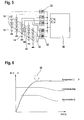
- the control behavior of in FIG. 5 illustrated arrangement shows FIG. 6 :
- the top curve (temperature) corresponds to the signal recorded by the sensor 34. Once this reaches the preset threshold (position of arrow 38 on the temperature curve in FIG. 6 ), is in the illustrated embodiment of the invention by driving the units 32 gradually lowered the current, resulting in a corresponding reduction of the luminous flux (middle curve of FIG. 6 ) leads.
- the FIG. 6 also illustrates how, in the right area, the decrease of the current leads to a state of equilibrium of the temperature at the height of the temperature threshold, so that as far as a stationary operating state is reached, which allows maximum light output with minimum thermal load of the LED array.
- the present invention is not limited to the embodiment shown, it is particularly contemplated by the present invention to provide a different number of LEDs, as well as other approaches to power control and temperature sensing of LED temperature development. Also in mechanical terms, the embodiment shown is to be understood as merely exemplary, and any other forms of implementation appear conceivable, which combine the advantageous temperature characteristics of an LED-based light, especially outdoor light, with flexible adjustability.
Abstract
Description
- Die vorliegende Erfindung betrifft eine Leuchtenvorrichtung nach dem Oberbegriff des Hauptanspruchs. Eine derartige Leuchtenvorrichtung, beispielsweise realisiert als sogenannte Außenleuchte zur stationären Montage an einer Hauswand, ist aus dem Stand der Technik allgemein bekannt, wobei insbesondere die günstigen Eigenschaften von (Leistungs-)LEDs im Hinblick auf Wirkungsgrad, Lichtausbeute und günstige Stromaufnahme benutzt werden, um kostengünstig Bereiche etwa im privaten oder industriellen Umfeld auszuleuchten. Dabei ist es nicht unüblich, gängige LEDs nicht einzeln, sondern gruppenweise auf bzw. an einem Leuchtmittelträger anzuordnen und gemeinsam zu betreiben, um so die gewünschte Lichtstärke zu realisieren.
- Allerdings ist das Leuchtverhalten bzw. die Lichtausbeute derartiger (Halbleiter basierter) LEDs temperaturabhängig, wobei sich nicht nur eine sehr hohe Umgebungstemperatur nachteilig auf die Lichtausbeute auswirkt, auch wirkt die gerade bei Leistungs-LEDs (derartige Leuchtmittel sind in Leistungsbereichen von typischerweise 100mW bis ca. 3W erhältlich, wobei Lichtausbeuten von 1001m/W und mehr erreicht werden) unvermeidliche Verlustleistung zu einer potenziell schädlichen Wärmeentwicklung, die nicht nur zu einem deutlichen Sinken der Lichtausbeute, sondern zu einer deutlichen Verringerung der Lebensdauer des Halbleiters führen kann.
- Insbesondere im Zusammenhang mit einem geplanten Einsatz als Leuchte in Außenbereich sind damit komplexe Temperaturbedingungen vorhanden, welche den Einsatz von LED-basierten Leuchten begrenzen bzw. Sicherheitsmaßnahmen dahingehend erfordern, dass etwa derartige LEDs nur mit einem Teil ihrer maximalen elektrischen Leistung angesteuert werden.
- Aufgabe der vorliegenden Erfindung ist es daher, gattungsbildende, mindestens eine LED als Leuchtmittel aufweisende Leuchtenvorrichtungen im Hinblick auf ihre Eignung für Umgebungen mit stark wechselnden bzw. hohen Umgebungstemperaturen zu verbessern, dabei insbesondere dafür zu sorgen, dass in Wärme umgesetzte Verlustleistung der LED selbst bzw. einer vorgeschalteten Steuerelektronik nicht zu einer nachteiligen Beeinflussung des Leucht- und Betriebsverhaltens der Vorrichtung führt und insbesondere die Universalität im Einsatz einer solchen Vorrichtung erhöht wird.
- Die Aufgabe wird durch die Leuchtenvorrichtung mit den Merkmalen des Hauptanspruchs gelöst; vorteilhafte Weiterbildungen der Erfindung sind in den Unteransprüchen beschrieben.
- In erfindungsgemäß vorteilhafter Weise ist der mindestens einen LED ein Temperatursensor so zugeordnet, dass dieser in einem geeigneten Erwärmungsbereich des Leuchtmittelträgers eine aktuelle Temperatur der mindestens einen LED erfasst und diesen elektronisch erfassten Temperaturwert so der erfindungsgemäßen, Steuerelektronik anlegt, dass diese eine Feststellung darüber treffen kann, ob ein (geeignet vorbestimmter bzw. voreingestellter) Schwellwert erreicht oder überschritten wird, woraufhin dann durch Steuerung der Steuerelektronik eine Verminderung der der LED zugeführten elektrischen Leistung erfolgt. Dies hat dann die Konsequenz, dass die von der LED erzeugte Verlustleistung und mithin die (schädliche) Wärmeerzeugung vermindert werden kann, sodass, insbesondere bei Ausgestaltung der Steuerelektronik als Regelvorrichtung mit der Temperatur als Regelgröße, ein Leuchtbetrieb eingestellt werden kann, welcher maximal mögliche Lichtausbeute der mindestens einen LED mit einer dem vorbestimmten Temperaturschwellwert entsprechenden maximal gehaltenen Temperatur am Leuchtmittelträger kombiniert.
- Im Rahmen der Erfindung soll dabei als "LED" bevorzugt eine sogenannte Leistungs-LED gelten, nämlich eine LED einer Lichtausbeute von typischerweise 501m/W oder mehr und/oder einer Leistungsaufnahme von mindestens 100mW, wobei bevorzugt weißes Licht abgestrahlt wird, die vorliegende Erfindung ist jedoch im Hinblick auf das Merkmal "LED" prinzipiell für jede lichtemittierende Diode geeignet und vorgesehen, welche durch eigene (verlustleistungsbedingte) Erwärmung in ihrer Lebensdauer und/oder Lichtausbeute potenziell beeinträchtigt ist.
- Der vorbestimmte Temperaturschwellwert im Rahmen der vorliegenden Erfindung wird dabei von der Temperatur in der lichterzeugenden Schicht des Halbleiters (sogenannte Junction-Temperatur) bestimmt und liegt bei praktischen Ausführungsformen der vorliegenden Erfindung typischerweise bei etwa 80°C, sodass in bevorzugten Realisierungen der Erfindung ein vorbestimmter Temperaturschwellwert von 75°C, bevorzugt 85°C und weiter bevorzugt 90°C gilt, bei Überschreiten desselben dann erfindungsgemäß die Leistungsverringerung in der elektrischen Ansteuerung der zugehörigen LED(s) erfolgt.
- In vorteilhafter Weiterbildung der Erfindung geschieht dabei durch Wirkung der erfindungsgemäßen Steuerelektronik das Verringern der zugeführten elektrischen Leistung stufenlos sowie weiter bevorzugt über einen Zeitraum von mehreren Sekunden bzw. gar Minuten (etwa in der Größenordnung des Erwärmungs- bzw. Abkühlungszeitraums des Leuchtmittelträgers), bedingt durch die thermischen Eigenschaften des Leuchtmittelträgers bzw. des Erwärmungsbereichs, sodass das menschliche Auge eine mit der elektrischen Leistungsverringerung verbundene Abnahme der Beleuchtungsstärke praktisch nicht wahrnimmt. Insbesondere in der Ausgestaltung der Erfindung (genauer: der Steuerelektronik) als Regelvorrichtung, wobei die Temperatur des Erwärmungsbereiches durch geeignete elektrische Leistungsregelung des (der) Leuchtmittel(s) innerhalb eines vorbestimmten Bereichs um den Temperaturschwellwert herum gehalten wird, lässt sich damit in beleuchtungstechnisch und energetisch optimierter Weise bei gleichzeitig bestmöglichem Schutz für das/die Leuchtmittel ein dauerhafter Beleuchtungsbetrieb der erfindungsgemäßen Leuchtenvorrichtung gewährleisten.
- In der praktischen Realisierung des Temperatursensors ist es dabei bevorzugt, diesen als temperaturempfindlichen Widerstand (bzw. Halbleiter) zu realisieren, wobei, etwa als Widerstand mit einer NTC-Charakteristik, der temperaturabhängige Widerstandsverlauf geeignet erfasst und als Grundlage für eine Steuerung oder Regelegung verwendet wird. Dabei erfolgt bevorzugt die Realisierung der Steuerelektronik digital, unter Einsatz eines gängigen Mikrocontrollers oder dergleichen Steuereinheit, wobei dann das Ausgangssignal des Temperatursensors geeignet digitalisiert und als Eingangsgröße verwendet wird. Bevorzugt erfolgt zudem die Ansteuerung der mindestens einen LED in der Art einer getakteten, steuerbaren Stromquelle, wobei mittels Pulsweitenmodulationen (PWM) die Leistungsansteuerung erfolgen kann.
- Besonders günstig ist die erfindungsgemäße Steuerelektronik zusätzlich vorgesehen, um weiterbildungsgemäß vorgesehene Bewegungs- und/oder Helligkeitssensorik anzusteuern bzw. derartige Sensorsignale zu verarbeiten; so ist es insbesondere von einer bevorzugten Realisierung der Erfindung umfasst, die erfindungsgemäße Leuchtenvorrichtung als sogenannte Sensorleuchte mit einer (typischerweise infrarot- oder radarbasierten) Bewegungssensoreinheit auszustatten, welche als Reaktion auf detektierte Bewegung eines Erfassungsobjektes, z. B. einer sich im Erfassungsbereich vor der Leuchte bewegenden Person, die Leuchte in einen Leuchtenbetrieb aktiviert. Im Fall einer Helligkeitssteuerung kann im Rahmen bevorzugter Weiterbildungen der Erfindung entweder ein detektierter Umgebungshelligkeitspegel eine Leuchtmittelaktivierung verhindern (z. B. bei hellem Umgebungslicht), ergänzend oder alternativ kann eine bevorzugt vorgesehene Helligkeitssensorik, etwa bei dämmriger Außenumgebung, einen (schwachen) Helligkeits-Grundpegel des/der Leuchtmittel vorgeben, welcher dann als Reaktion auf z. B. detektierte Bewegung einen Anstieg der Beleuchtungshelligkeit der LED hervorruft. Eine weiterbildungsgemäß vorgesehene Zeitschalteinheit im Rahmen der Steuerelektronik würde im Fall eines Sensorbetriebs dafür sorgen, dass die Leuchtmittel über eine vorbestimmte Mindest-Einschaltdauer eingeschaltet bleiben, auch wenn keine (weitere) Bewegung detektiert wird, und auch während einer solchen (Mindest-) Einschaltdauer würde dann gemäß der Erfindung eine von der detektierten Temperatur abhängige Leistungssteuerung bzw. -regelung der zugeführten elektrischen Leistungen erfolgen.
- Im Rahmen bevorzugter mechanischer Realisierungsformen der vorliegenden Erfindung liegt es, den Leuchtmittelträger flach und zum Aufnehmen einer Mehrzahl von in (bevorzugt regelmäßiger) Array-Form angeordneter LEDs vorzusehen. Die der so gebildeten Lichtaustrittsseite rückwärtig gegenüberliegende Flachseite des Leuchtmittelträgers ist dann weiterbildungsgemäß geeignet mit Kühlrippen oder dergleichen Kühlkörperabschnitten zur Abgabe unerwünschter Wärme und damit zur weiteren thermischen Optimieren der Gesamtanordnung auszugestalten. Der erfindungsgemäße Temperatursensor ist dann bevorzugt in unmittelbarer Nähe der LEDs, etwa um oder im Lichtaustrittsbereich, thermisch gekoppelt vorzusehen.
- Im Rahmen bevorzugter Weiterbildungen der Erfindung liegt es zudem, den Leuchtmittelträger (gegenüber einem typischerweise zur stationären Befestigung der Leuchtenvorrichtung verwendeten Leuchtensockel) bewegbar auszugestalten, mit dem Zweck, für eine jeweilige Beleuchtungssituation eine optimale Einstellung zu gewährleisten. Dabei liegt es im Rahmen bevorzugter Weiterbildungen, eine Verschwenkung um mindestens eine Achse, bevorzugt um zwei Achsen, zu realisieren, wobei in besonders geeigneter Weise eine horizontale Verschwenkung des Leuchtmittelträgers um ein eine Horizontalachse bestimmendes Gelenk erfolgt, mit welchem der (flache) Leuchtmittelträger an einem den Leuchtmittelträger mit dem Leuchtensockel verbindenden Schwenkarm befestigt ist. Dieser Schwenkarm kann dann ergänzend oder alternativ zusätzlich zum Ausbilden einer vertikalen Schwenkachse (z. B. über ein entsprechendes Gelenk am Leuchtensockel) bewegbar ausgebildet sein.
- Durch die erfindungsgemäße Temperatursteuerung bzw. -regelung weist die erfindungsgemäße Vorrichtung deutliche Vorteile im Hinblick auf eine Wärmeentwicklung am Leuchtmittelträger auf, sodass -- etwa gegenüber mittels Halogenstrahlern oder dergleichen stark wärmeentwickelnden Leuchtmitteln zur Realisierung von Außenleuchten -- keine Vorkehrungen getroffen werden müssen, welche etwa einen wirksamen Schwenkbereich des Leuchtmittelträgers begrenzen: So kann etwa die vorliegende Erfindung in vorteilhafter Weise einen sehr weiten (typischerweise von 180° oder sogar darüber hinaus reichenden) horizontalen und/oder vertikalen Schwenkbereich ausbilden, mit dem Ergebnis, dass etwa bei an einer Hauswand befestigtem Leuchtensockel und maximaler Verschwenkung um die Vertikalachse, ein Lichtkegel aus dem Leuchtmittelträger heraus bis auf die Befestigungswand verschwenkt werden kann, ein Umstand, der etwa bei bekannten Halogenleuchten durch brandschutztechnische Vorschriften und entsprechende Vorgaben an die traditionelle Gehäusekonstruktion und deren Verschwenkbarkeit, unterbunden werden muss.
- Damit ermöglicht die vorliegende Erfindung auch völlig neue und flexible Möglichkeiten der Verstellung von Leuchten, insbesondere von Wandleuchten sowie im Außenbereich. Weitere Vorteile, Merkmale und Einzelheiten der Erfindung ergeben sich aus der nachfolgenden Beschreibung bevorzugter Ausführungsbeispiele sowie anhand der Zeichnungen; diese zeigen in
- Figur 1:
- eine perspektivische Ansicht einer Leuchtenvorrichtung gemäß einer ersten Ausführungsform der vorliegenden Erfindung;
- Figur 2:
- eine perspektiv-rückwärtige Ansicht der Anordnung gemäß
Figur 1 , jedoch mit um 90° um die Vertikalachse verschwenktem Leuchtmittelträger; - Figur 3:
- eine Seitenansicht auf die Vorrichtung und Anordnung gemäß
Figur 1 ; - Figur 4:
- eine Draufsicht auf die Vorrichtung und Anordnung gemäß
Figur 1 ; - Figur 5:
- ein schematisches Schaltbild der Temperaturerfassung im Erwärmungsbereich sowie der elektrischen Ansteuerung der Mehrzahl von LEDs im Ausführungsbeispiel der
Figuren 1 bis 4 sowie - Figur 6:
- ein Diagramm mit dem Verlauf der Temperatur im Erwärmungsbereich, des von den LEDs emittierten Lichtstroms sowie der anliegenden elektrischen Stromstärke, jeweils aufgetragen über der Zeit.
- Die
Figuren 1 bis 4 verdeutlichen den mechanischen Aufbau sowie die Einstellbarkeit der Leuchtenvorrichtung gemäß einer ersten bevorzugten Ausführungsform der Erfindung: Ein als flaches Kunststoffgehäuse 10 mit einem rückwärtigen Kühlkörperbereich 12 versehener Leuchtmittelträger ist zur Aufnahme von insgesamt fünfundzwanzig Leistungs-LEDs 14 ausgebildet (jeweilige elektrische Leistungsaufnahme 2 W), wobei die LEDs hinter einer transparenten Abdeckscheibe sitzen und in der inFigur 1 gezeigten Weise einen Lichtaustrittsbereich mit einer Matrix von 5x5 einzelnen Leuchtmitteln als Lichtquellen ausbilden. Das Leuchtmittelträgergehäuse 10 ist in der gezeigten Weise mit einem als Winkelarm 16 realisierten Schwenkarm so verbunden, dass ein endseitig am Arm 16 gebildetes Gelenk 18 zur Verbindung mit dem Gehäuse 10 eine horizontale Schwenkachse für dieses definiert, wobei der Anlenkpunkt am Gehäuse 10 sowie die Länge des Schwenkarms 16 so eingerichtet bzw. bemessen sind, dass in der inFigur 3 gezeigten Weise ein Verschwenken des Gehäuses 10 relativ zu einem stationären (und z. B. an einer Wand befestigten) Lampensockel 20 um 180° um die Horizontalachse ermöglicht ist. Damit würde in einer ersten möglichen Endstellung einer solchen Verschwenkung der Lichtaustrittsbereich nach oben, in einer gegenüberliegend verschwenkten Stellung abwärts gerichtet auf einen unterliegenden Boden reichen können. - Wie die
Figuren 1 bis 4 zudem verdeutlichen, sitzt der Schwenkarm 16 über einen integralen Aufsatzabschnitt 22 so auf dem Sockel 20 auf, dass durch Relativdrehung zwischen 20 und 22 ein Verschwenken des Leuchtmittelträgers 10 um eine von 20, 22 gebildete Vertikalachse ermöglicht ist. Die Draufsicht derFigur 4 deutet den Verschwenkungsbereich um diese Vertikalachse an, nämlich wiederum mindestens 180°, sodass in einer ersten Verschwenkungsstellung (z. B. in der Figurenebene nach rechts) der Lichtaustrittsbereich 90° seitwärts gerichtet ist, entsprechend ist dies in der umgekehrten Richtung möglich. Wird der vertikale Schwenkbereich etwa über die 180° erweitert, ist es im Rahmen der vorliegenden Weiterbildung gar ermöglicht, den Lichtaustrittsbereich auf die (nicht gezeigte) Befestigungswand zu richten, wobei in erfindungsgemäß synergistischer Weise der Einsatz der LEDs in Verbindung mit der temperaturabhängigen Leistungssteuerung wirksam jeglichen nachteiligen Einfluss auf diese Wand bei unmittelbarer Bestrahlung durch Wärmeentwicklung (wie es etwa bei Halogenleuchten der Fall wäre) verhindert. - Die Ansichten der
Figuren 1, 2 ,3 verdeutlichen zudem, wie am Leuchtensockel, dem Armabschnitt 22 axial gegenüberliegend, ein (ansonsten bekannter) verstellbarer Bewegungssensorabschnitt 24 gebildet ist; wiederum in ansonsten bekannter Weise kann zum Zweck der bewegungsabhängigen Steuerung der Leuchten eine gezeigte Infrarotlinse 26 der Sensoreinheit 24 auf einen zu überwachenden Beobachtungsbereich eingestellt werden. - Die
Figur 5 verdeutlicht die elektrische bzw. schaltungstechnische Realisierung der Erfindung am Ausführungsbeispiel derFiguren 1 bis 4 : Gezeigt sind, wie die insgesamt 25 LEDs 14, in Reihe verschaltet zu Gruppen von je fünf, von einer als Funktionsblock 30 gezeigten und mittels eines gängigen Microcontrollers realisierten Steuereinheit angesteuert werden, und zwar über eine mittels Pulsweitenmodulation (PWM) als gesteuerte Stromquelle realisierte Treiberschaltung 32, welche einem jeweiligen Zweig von LEDs zugeordnet ist. Ein als NTC 34 realisierter Temperatursensor ist (in denFiguren 1 bis 4 nicht gezeigt) hinter der Frontfläche im Erwärmungsbereich der LEDs angeordnet und, angedeutet durch die gemusterte Fläche 36 inFigur 5 , thermisch mit den LEDs verbunden. Der entsprechend negativ temperaturabhängige Widerstandswert des Thermosensors wird von einem Analog-Digitalwandler-Eingang (A/D) der als geeignet programmierter Microcontroler realisierten Steuerelektronik 30 digitalisiert und mit einem einstellbaren bzw. voreingestellten Schwellwert für eine maximale Temperatur der LEDs, z. B. 80°, verglichen. - Das Steuer- bzw. Regelverhalten der in
Figur 5 illustrierten Anordnung zeigtFigur 6 : Die oberste Kurve (Temperatur) entspricht dem vom Sensor 34 aufgenommenen Signal. Sobald dieses den voreingestellten Schwellwert (Position des Pfeils 38 an der Temperaturkurve inFigur 6 ) erreicht, wird im Rahmen des gezeigten Ausführungsbeispiels der Erfindung durch Ansteuerung der Einheiten 32 graduell die Stromstärke abgesenkt, was zu einer entsprechenden Absenkung des Lichtstroms (mittlere Kurve derFigur 6 ) führt. Dies geschieht jedoch mit relativ langer Zeitkonstante (diese liegt im Bereich des Erwärmungs- bzw. Abkühlungsverhaltens des Leuchtmittelträgers durch die LEDs), sodass das langsame Absenken der Stromstärke und das entsprechende Absinken des Lichtstroms über den Zeitraum vom menschlichen Auge praktisch nicht wahrgenommen wird. DieFigur 6 verdeutlicht zudem, wie, im rechten Bereich, das Absinken der Stromstärke zu einem Gleichgewichtszustand der Temperatur auf der Höhe des Temperaturschwellwerts führt, sodass in soweit ein stationärer Betriebszustand erreicht ist, welcher eine maximale Lichtausbeute bei minimaler thermischer Belastung des LED-Arrays ermöglicht. - Die vorliegende Erfindung ist nicht auf das gezeigte Ausführungsbeispiel beschränkt, so ist es insbesondere von der vorliegenden Erfindung umfasst, eine abweichende Anzahl von LEDs vorzusehen, genauso wie andere Vorgehensweisen bei der Leistungssteuerung bzw. Leistungsregelung sowie der Temperaturerfassung der LED-Temperaturentwicklung. Auch in mechanischer Hinsicht ist das gezeigte Ausführungsbeispiel als lediglich exemplarisch zu begreifen, und beliebige andere Realisierungsformen erscheinen denkbar, welche die vorteilhaften Temperatureigenschaften einer LED-basierten Leuchte, insbesondere Außenleuchte, mit flexibler Verstellbarkeit kombinieren.
Claims (15)
- Leuchtenvorrichtung mit
einem mindestens eine LED (14) als Leuchtmittel aufweisenden Leuchtmittelträger (10)
und einer der mindestens einen LED zugeordneten Steuerelektronik (30), die zum gesteuerten Aktivieren der LED ausgebildet ist,
dadurch gekennzeichnet, dass
in einem Erwärmungsbereich (36) der LED am Leuchtmittelträger ein zum Detektieren einer Temperatur der LED ausgebildeter Temperatursensor (34) vorgesehen ist, der so zum Zusammenwirken mit der Steuerelektronik ausgebildet ist, dass als Reaktion auf ein Erreichen oder Überschreiten eines vorbestimmten Temperaturschwellwertes die Steuerelektronik eine der mindestens einen LED zugeführte elektrische Leistung verringert. - Vorrichtung nach Anspruch 1,
dadurch gekennzeichnet, dass die Steuerelektronik und/oder die thermischen Eigenschaften des Erwärmungsbereichs und des Leuchtmittelträgers so eingerichtet sind, dass das Verringern der zugeführten elektrischen Leistung stufenlos und/oder über einen Zeitraum erfolgt, der vom menschlichen Auge nicht als Lichtstärkenänderung wahrnehmbar ist. - Vorrichtung nach Anspruch 1 oder 2,
dadurch gekennzeichnet, dass die Steuerelektronik zum Regeln der zugeführten elektrischen Leistung so ausgebildet ist, dass eine vom Temperatursensor erfasste Betriebstemperatur der mindestens einen LED einen vorbestimmten Abstand vom Temperaturschwellwert nicht überschreitet. - Vorrichtung nach einem der Ansprüche 1 bis 3,
dadurch gekennzeichnet, dass der Leuchtmittelträger (10) eine Mehrzahl von gemeinsam von der Steuerelektronik angesteuerten LEDs (14) trägt, denen der Temperatursensor in Form eines temperaturempfindlichen Widerstands- und/oder Halbleiterelements (34) gemeinsam zugeordnet ist. - Vorrichtung nach einem der Ansprüche 1 bis 4,
gekennzeichnet durch einen mit der Steuerelektronik zusammenwirkenden Bewegungs- und/oder Helligkeitssensor (24), der zum bewegungs- bzw. helligkeitsabhängigen Aktivieren der mindestens einen LED ausgebildet ist. - Vorrichtung nach einem der Ansprüche 1 bis 5,
dadurch gekennzeichnet, dass der Leuchtmittelträger als bevorzugt flach ausgebildeter Körper (10) realisiert ist, der auf einer Flachseite einen Lichtaustrittsbereich für die mindestens eine LED und auf einer der Flachseite gegenüberliegenden Flachseite einen Kühlkörperabschnitt (12) für Abwärme anbietet. - Vorrichtung nach einem der Ansprüche 1 bis 6,
dadurch gekennzeichnet, dass der Leuchtmittelträger als gegenüber einem Leuchtensockel (20) der Leuchtenvorrichtung schwenkbar ausgebildeter, flacher Körper so eingerichtet ist, dass bei fest montiertem Leuchtensockel der Leuchtmittelträger in Richtung auf ein zu beleuchtendes Objekt verstellbar ist. - Vorrichtung nach Anspruch 7,
dadurch gekennzeichnet, dass der Leuchtmittelträger an einem den Leuchtmittelträger mit dem Leuchtensockel verbindenden Schwenkarm (16) so befestigt ist, dass ein Verschwenken des Leuchtmittelträgers um eine Horizontalachse ermöglicht ist. - Vorrichtung nach Anspruch 7 oder 8,
dadurch gekennzeichnet, dass der Leuchtmittelträger an einem den Leuchtmittelträger mit dem Leuchtensockel verbindenden Schwenkarm (16) so befestigt ist, dass ein Verschwenken des Leuchtmittelträgers um eine Vertikalachse ermöglicht ist. - Vorrichtung nach Anspruch 8 oder 9,
dadurch gekennzeichnet, dass der Schwenkarm (16) so ausgebildet ist, dass ein horizontales Verschwenken um die Horizontalachse und/oder ein vertikales Verschwenken um die Vertikalachse innerhalb eines Schwenkbereichs von mindestens 180° ermöglicht ist. - Vorrichtung nach einem der Ansprüche 7 bis 10,
dadurch gekennzeichnet, dass der Schwenkarm gewinkelt ausgebildet und einends an einer Flachseite des Leuchtenkörpers angelenkt ist. - Vorrichtung nach einem der Ansprüche 7 bis 11,
dadurch gekennzeichnet, dass der Leuchtensockel zur Montage an einer Vertikalfläche, insbesondere Hauswand, ausgebildet ist. - Vorrichtung nach einem der Ansprüche 7 bis 12,
dadurch gekennzeichnet, dass der Leuchtensockel zur Aufnahme einer elektrischen Zuleitung zur Stromversorgung der Steuerelektronik sowie der mindestens einen LED ausgebildet ist. - Vorrichtung nach einem der Ansprüche 7 bis 13,
dadurch gekennzeichnet, dass der Leuchtensockel (20) zur Aufnahme einer Bewegungssensoreinheit (24) ausgebildet ist. - Vorrichtung nach einem der Ansprüche 1 bis 14,
dadurch gekennzeichnet, dass die Leuchtenvorrichtung als Außenleuchte, insbesondere Sensor-Außenleuchte, feuchtigkeits- und/oder staubgeschützt ausgebildet ist.
Priority Applications (1)
| Application Number | Priority Date | Filing Date | Title |
|---|---|---|---|
| PL09004657T PL2107295T3 (pl) | 2008-04-03 | 2009-03-31 | Urządzenie lampowe z diodami LED |
Applications Claiming Priority (1)
| Application Number | Priority Date | Filing Date | Title |
|---|---|---|---|
| DE102008017483A DE102008017483A1 (de) | 2008-04-03 | 2008-04-03 | Leuchtenvorrichtung |
Publications (3)
| Publication Number | Publication Date |
|---|---|
| EP2107295A2 true EP2107295A2 (de) | 2009-10-07 |
| EP2107295A3 EP2107295A3 (de) | 2010-09-08 |
| EP2107295B1 EP2107295B1 (de) | 2014-04-16 |
Family
ID=40887111
Family Applications (1)
| Application Number | Title | Priority Date | Filing Date |
|---|---|---|---|
| EP09004657.4A Not-in-force EP2107295B1 (de) | 2008-04-03 | 2009-03-31 | Leuchtenvorrichtung mit LEDs |
Country Status (3)
| Country | Link |
|---|---|
| EP (1) | EP2107295B1 (de) |
| DE (1) | DE102008017483A1 (de) |
| PL (1) | PL2107295T3 (de) |
Cited By (6)
| Publication number | Priority date | Publication date | Assignee | Title |
|---|---|---|---|---|
| WO2012093291A1 (en) | 2011-01-07 | 2012-07-12 | Iq Group Sdn Bhd | A floodlight module with an elbow connector |
| DE102011111970A1 (de) | 2011-08-31 | 2013-02-28 | Abb Ag | LED-Modul-System mit einem LED-Modul |
| EP2644988A1 (de) * | 2012-03-30 | 2013-10-02 | Ansorg GmbH | Elektrische Beleuchtungsvorrichtung mit um mehrere Achsen schwenkbarem Leuchtenkopf |
| US20140169004A1 (en) * | 2011-09-27 | 2014-06-19 | Toshiba Lighting & Technology Corporation | Lamp Device and Luminaire |
| CN106907611A (zh) * | 2015-12-21 | 2017-06-30 | 威海市公安局文登分局 | 一种光控led补光灯 |
| EP2924334B1 (de) * | 2014-03-28 | 2019-07-24 | Swarco Futurit Verkehrssignalsysteme Ges.m.b.H. | Straßenleuchte in LED-Technologie |
Families Citing this family (9)
| Publication number | Priority date | Publication date | Assignee | Title |
|---|---|---|---|---|
| DE102010002227A1 (de) * | 2010-02-23 | 2011-08-25 | Tridonic Ag | Schutz von LEDs gegen Überhitzung und zu hohem Durchgangsstrom |
| DE202012100891U1 (de) | 2012-03-13 | 2013-06-14 | Steinel Gmbh | Leuchtenvorrichtung |
| DE202012104404U1 (de) * | 2012-11-15 | 2014-02-17 | Zumtobel Lighting Gmbh | Schaltung zum Betreiben einer Lichtquelle mit Temperaturüberwachung |
| US9677754B2 (en) | 2014-11-07 | 2017-06-13 | Chm Industries, Inc. | Rotating light emitting diode driver mount |
| DE102016123533A1 (de) * | 2016-12-06 | 2018-06-07 | Rev Ritter Gmbh | LED-Strahler sowie Anschlussgehäuse für einen LED-Strahler |
| CN106764823A (zh) * | 2016-12-09 | 2017-05-31 | 重庆新派新智能科技有限公司 | 园林路灯 |
| CN110440176A (zh) * | 2018-05-03 | 2019-11-12 | 佛山市顺德区欣久照明有限公司 | 光感热红外感应带应急壁灯 |
| CN110906237B (zh) * | 2019-12-13 | 2021-09-14 | 安徽世林照明股份有限公司 | 一种快速配置智能照明设备及其工作方法 |
| DE102020106841A1 (de) | 2020-03-12 | 2021-09-16 | Steinel Gmbh | Strahleranordnung |
Citations (10)
| Publication number | Priority date | Publication date | Assignee | Title |
|---|---|---|---|---|
| US5649761A (en) | 1995-08-11 | 1997-07-22 | Larry C. Y. Lee | Motion detector with side-pivoting light fixture |
| EP1313353A1 (de) | 2001-11-19 | 2003-05-21 | Nokia Corporation | Verfahren und Anordnung zum Betreiben einer Leuchtdiode |
| FR2838178A1 (fr) | 2002-04-09 | 2003-10-10 | Oxo | Projecteur multidirectionnel a diodes |
| JP2004355934A (ja) | 2003-05-28 | 2004-12-16 | Toshiba Lighting & Technology Corp | 発光ダイオード照明装置 |
| US20050007025A1 (en) | 2003-07-08 | 2005-01-13 | Gauna Kevin Wayne | Dual LED/incandescent security fixture |
| US20060061991A1 (en) | 2004-09-17 | 2006-03-23 | Chuan-Fang Yeh | Light assembly with mounting member |
| DE102004047682A1 (de) | 2004-09-30 | 2006-04-06 | Patent-Treuhand-Gesellschaft für elektrische Glühlampen mbH | LED-Array |
| DE102004055884A1 (de) | 2004-11-19 | 2006-05-24 | Audi Ag | Leuchteinrichtung für ein Kraftfahrzeug umfassend eine oder mehrere LED's |
| DE102005004246A1 (de) | 2005-01-28 | 2006-08-10 | Erco Leuchten Gmbh | Vorrichtung zur Befestigung einer Leuchte an einer raumfesten Fläche |
| WO2007036871A2 (en) | 2005-09-27 | 2007-04-05 | Koninklijke Philips Electronics N.V. | Led landscape lighting fixture |
Family Cites Families (12)
| Publication number | Priority date | Publication date | Assignee | Title |
|---|---|---|---|---|
| DE19728763B4 (de) * | 1997-07-07 | 2007-10-31 | Reitter & Schefenacker Gmbh & Co. Kg | Schaltungseinrichtung zum Schutz von strombetriebenen Leuchtmitteln, insbesondere von LEDs, zu Signal- oder Beleuchtungszwecken |
| DE29809655U1 (de) * | 1998-05-29 | 1998-12-10 | Steinel Gmbh & Co Kg | Strahler |
| DE19930174A1 (de) * | 1999-06-30 | 2001-01-04 | Patent Treuhand Ges Fuer Elektrische Gluehlampen Mbh | Ansteuerschaltung für LED und zugehöriges Betriebsverfahren |
| US6196705B1 (en) * | 1999-08-09 | 2001-03-06 | Steinel Gmbh & Co. Kg | Halogen motion detection security light positioning system |
| CA2336497A1 (en) * | 2000-12-20 | 2002-06-20 | Daniel Chevalier | Lighting device |
| DE20110137U1 (de) * | 2001-06-19 | 2001-09-13 | Heizmann Michael | Lampe |
| DE10134246A1 (de) * | 2001-07-18 | 2003-02-06 | Patent Treuhand Ges Fuer Elektrische Gluehlampen Mbh | Betriebsgerät für Leuchtdioden mit temperaturabhängiger Stromregelung |
| US6617795B2 (en) * | 2001-07-26 | 2003-09-09 | Koninklijke Philips Electronics N.V. | Multichip LED package with in-package quantitative and spectral sensing capability and digital signal output |
| DE10214447A1 (de) * | 2002-03-30 | 2003-10-16 | Hella Kg Hueck & Co | Regeleinrichtung zum Regeln von elektrischen Leuchtmitteln und Scheinwerfer mit einer solchen Regeleinrichtung |
| DE102004060890A1 (de) * | 2004-12-17 | 2006-06-29 | Patent-Treuhand-Gesellschaft für elektrische Glühlampen mbH | Kfz-Scheinwerferelement |
| US7414370B2 (en) * | 2006-02-03 | 2008-08-19 | Honeywell International Inc. | Increasing reliability of operation of light emitting diode arrays at higher operating temperatures and its use in the lamps of automobiles |
| US7766511B2 (en) * | 2006-04-24 | 2010-08-03 | Integrated Illumination Systems | LED light fixture |
-
2008
- 2008-04-03 DE DE102008017483A patent/DE102008017483A1/de not_active Withdrawn
-
2009
- 2009-03-31 PL PL09004657T patent/PL2107295T3/pl unknown
- 2009-03-31 EP EP09004657.4A patent/EP2107295B1/de not_active Not-in-force
Patent Citations (10)
| Publication number | Priority date | Publication date | Assignee | Title |
|---|---|---|---|---|
| US5649761A (en) | 1995-08-11 | 1997-07-22 | Larry C. Y. Lee | Motion detector with side-pivoting light fixture |
| EP1313353A1 (de) | 2001-11-19 | 2003-05-21 | Nokia Corporation | Verfahren und Anordnung zum Betreiben einer Leuchtdiode |
| FR2838178A1 (fr) | 2002-04-09 | 2003-10-10 | Oxo | Projecteur multidirectionnel a diodes |
| JP2004355934A (ja) | 2003-05-28 | 2004-12-16 | Toshiba Lighting & Technology Corp | 発光ダイオード照明装置 |
| US20050007025A1 (en) | 2003-07-08 | 2005-01-13 | Gauna Kevin Wayne | Dual LED/incandescent security fixture |
| US20060061991A1 (en) | 2004-09-17 | 2006-03-23 | Chuan-Fang Yeh | Light assembly with mounting member |
| DE102004047682A1 (de) | 2004-09-30 | 2006-04-06 | Patent-Treuhand-Gesellschaft für elektrische Glühlampen mbH | LED-Array |
| DE102004055884A1 (de) | 2004-11-19 | 2006-05-24 | Audi Ag | Leuchteinrichtung für ein Kraftfahrzeug umfassend eine oder mehrere LED's |
| DE102005004246A1 (de) | 2005-01-28 | 2006-08-10 | Erco Leuchten Gmbh | Vorrichtung zur Befestigung einer Leuchte an einer raumfesten Fläche |
| WO2007036871A2 (en) | 2005-09-27 | 2007-04-05 | Koninklijke Philips Electronics N.V. | Led landscape lighting fixture |
Cited By (9)
| Publication number | Priority date | Publication date | Assignee | Title |
|---|---|---|---|---|
| WO2012093291A1 (en) | 2011-01-07 | 2012-07-12 | Iq Group Sdn Bhd | A floodlight module with an elbow connector |
| DE212011100193U1 (de) | 2011-01-07 | 2013-08-27 | Iq Group Sdn Bhd | Flutlichtvorrichtung |
| DE102011111970A1 (de) | 2011-08-31 | 2013-02-28 | Abb Ag | LED-Modul-System mit einem LED-Modul |
| EP2566300A2 (de) | 2011-08-31 | 2013-03-06 | Abb Ag | LED-Modul-System |
| RU2637308C2 (ru) * | 2011-08-31 | 2017-12-04 | Абб Аг | Система led-модулей с led-модулем |
| US20140169004A1 (en) * | 2011-09-27 | 2014-06-19 | Toshiba Lighting & Technology Corporation | Lamp Device and Luminaire |
| EP2644988A1 (de) * | 2012-03-30 | 2013-10-02 | Ansorg GmbH | Elektrische Beleuchtungsvorrichtung mit um mehrere Achsen schwenkbarem Leuchtenkopf |
| EP2924334B1 (de) * | 2014-03-28 | 2019-07-24 | Swarco Futurit Verkehrssignalsysteme Ges.m.b.H. | Straßenleuchte in LED-Technologie |
| CN106907611A (zh) * | 2015-12-21 | 2017-06-30 | 威海市公安局文登分局 | 一种光控led补光灯 |
Also Published As
| Publication number | Publication date |
|---|---|
| EP2107295A3 (de) | 2010-09-08 |
| EP2107295B1 (de) | 2014-04-16 |
| PL2107295T3 (pl) | 2014-09-30 |
| DE102008017483A1 (de) | 2009-10-08 |
Similar Documents
| Publication | Publication Date | Title |
|---|---|---|
| EP2107295B1 (de) | Leuchtenvorrichtung mit LEDs | |
| EP2088369B1 (de) | Beleuchtungskörper | |
| EP2208926A1 (de) | Leuchtmittelmodul mit einer LED-Bestückung | |
| DE102007042646A1 (de) | LED-OP-Leuchte | |
| WO2014037359A1 (de) | Leuchte | |
| DE102007061160A1 (de) | Außenleuchte | |
| DE102011076128A1 (de) | Trägersystem und Lichtmodul zur Befestigung daran | |
| DE202010017320U1 (de) | Steh- oder Tischleuchte | |
| EP2454521A1 (de) | Elektrische leuchte | |
| DE102014205891A1 (de) | Leuchtmodul mit ringförmiger Leiterplatte | |
| DE102004011974A1 (de) | Leuchtmittel für eine Beleuchtungseinrichtung | |
| DE102009058310A1 (de) | LED-Leuchteneinsatz mit Lichtlenkelement | |
| DE202007013752U1 (de) | Schaltbarer Leucht- und Signalkörper und Hundehalsring | |
| DE102005014817A1 (de) | Signalleuchte, insbesondere für den Wetter ausgesetzten Außenbereich | |
| EP2244003A1 (de) | Strassenleuchte | |
| DE202005013699U1 (de) | Solar-Außenleuchte | |
| EP1530404A2 (de) | Licht und Wärmestrahler | |
| DE202010010263U1 (de) | Beleuchtungseinrichtung, insbesondere für einen Außenbereich | |
| DE102007058595A1 (de) | Sensorgesteuerte Leuchtenvorrichtung | |
| EP1691595A3 (de) | Gebläseregler für ein Fahrzeug | |
| EP2636948B1 (de) | LED-Lampe und Verfahren zum Betreiben einer derartigen Lampe | |
| DE102016104342B4 (de) | Beleuchtungsmodul und Straßen- oder Wegleuchte | |
| EP0961075A2 (de) | Strahler | |
| AT509230B1 (de) | Leuchte | |
| AT14933U1 (de) | Schaltung zum Betreiben einer Lichtquelle mit Temperaturüberwachung |
Legal Events
| Date | Code | Title | Description |
|---|---|---|---|
| PUAI | Public reference made under article 153(3) epc to a published international application that has entered the european phase |
Free format text: ORIGINAL CODE: 0009012 |
|
| AK | Designated contracting states |
Kind code of ref document: A2 Designated state(s): AT BE BG CH CY CZ DE DK EE ES FI FR GB GR HR HU IE IS IT LI LT LU LV MC MK MT NL NO PL PT RO SE SI SK TR |
|
| AX | Request for extension of the european patent |
Extension state: AL BA RS |
|
| PUAL | Search report despatched |
Free format text: ORIGINAL CODE: 0009013 |
|
| AK | Designated contracting states |
Kind code of ref document: A3 Designated state(s): AT BE BG CH CY CZ DE DK EE ES FI FR GB GR HR HU IE IS IT LI LT LU LV MC MK MT NL NO PL PT RO SE SI SK TR |
|
| AX | Request for extension of the european patent |
Extension state: AL BA RS |
|
| 17P | Request for examination filed |
Effective date: 20110225 |
|
| AKX | Designation fees paid |
Designated state(s): AT BE BG CH CY CZ DE DK EE ES FI FR GB GR HR HU IE IS IT LI LT LU LV MC MK MT NL NO PL PT RO SE SI SK TR |
|
| 17Q | First examination report despatched |
Effective date: 20121219 |
|
| RIC1 | Information provided on ipc code assigned before grant |
Ipc: F21V 23/00 20060101ALI20130627BHEP Ipc: H05B 33/08 20060101ALI20130627BHEP Ipc: F21Y 101/02 20060101ALN20130627BHEP Ipc: F21S 8/00 20060101AFI20130627BHEP Ipc: H05B 37/02 20060101ALI20130627BHEP |
|
| GRAP | Despatch of communication of intention to grant a patent |
Free format text: ORIGINAL CODE: EPIDOSNIGR1 |
|
| INTG | Intention to grant announced |
Effective date: 20131030 |
|
| GRAS | Grant fee paid |
Free format text: ORIGINAL CODE: EPIDOSNIGR3 |
|
| GRAA | (expected) grant |
Free format text: ORIGINAL CODE: 0009210 |
|
| AK | Designated contracting states |
Kind code of ref document: B1 Designated state(s): AT BE BG CH CY CZ DE DK EE ES FI FR GB GR HR HU IE IS IT LI LT LU LV MC MK MT NL NO PL PT RO SE SI SK TR |
|
| REG | Reference to a national code |
Ref country code: GB Ref legal event code: FG4D Free format text: NOT ENGLISH |
|
| REG | Reference to a national code |
Ref country code: CH Ref legal event code: EP |
|
| REG | Reference to a national code |
Ref country code: AT Ref legal event code: REF Ref document number: 662792 Country of ref document: AT Kind code of ref document: T Effective date: 20140515 |
|
| REG | Reference to a national code |
Ref country code: IE Ref legal event code: FG4D Free format text: LANGUAGE OF EP DOCUMENT: GERMAN |
|
| REG | Reference to a national code |
Ref country code: DE Ref legal event code: R096 Ref document number: 502009009170 Country of ref document: DE Effective date: 20140528 |
|
| REG | Reference to a national code |
Ref country code: CH Ref legal event code: NV Representative=s name: BODENSEEPATENT GMBH, CH |
|
| REG | Reference to a national code |
Ref country code: SE Ref legal event code: TRGR |
|
| REG | Reference to a national code |
Ref country code: NL Ref legal event code: VDEP Effective date: 20140416 |
|
| REG | Reference to a national code |
Ref country code: LT Ref legal event code: MG4D |
|
| REG | Reference to a national code |
Ref country code: PL Ref legal event code: T3 |
|
| PG25 | Lapsed in a contracting state [announced via postgrant information from national office to epo] |
Ref country code: BG Free format text: LAPSE BECAUSE OF FAILURE TO SUBMIT A TRANSLATION OF THE DESCRIPTION OR TO PAY THE FEE WITHIN THE PRESCRIBED TIME-LIMIT Effective date: 20140716 Ref country code: NL Free format text: LAPSE BECAUSE OF FAILURE TO SUBMIT A TRANSLATION OF THE DESCRIPTION OR TO PAY THE FEE WITHIN THE PRESCRIBED TIME-LIMIT Effective date: 20140416 Ref country code: IS Free format text: LAPSE BECAUSE OF FAILURE TO SUBMIT A TRANSLATION OF THE DESCRIPTION OR TO PAY THE FEE WITHIN THE PRESCRIBED TIME-LIMIT Effective date: 20140816 Ref country code: GR Free format text: LAPSE BECAUSE OF FAILURE TO SUBMIT A TRANSLATION OF THE DESCRIPTION OR TO PAY THE FEE WITHIN THE PRESCRIBED TIME-LIMIT Effective date: 20140717 Ref country code: LT Free format text: LAPSE BECAUSE OF FAILURE TO SUBMIT A TRANSLATION OF THE DESCRIPTION OR TO PAY THE FEE WITHIN THE PRESCRIBED TIME-LIMIT Effective date: 20140416 Ref country code: FI Free format text: LAPSE BECAUSE OF FAILURE TO SUBMIT A TRANSLATION OF THE DESCRIPTION OR TO PAY THE FEE WITHIN THE PRESCRIBED TIME-LIMIT Effective date: 20140416 Ref country code: NO Free format text: LAPSE BECAUSE OF FAILURE TO SUBMIT A TRANSLATION OF THE DESCRIPTION OR TO PAY THE FEE WITHIN THE PRESCRIBED TIME-LIMIT Effective date: 20140716 Ref country code: CY Free format text: LAPSE BECAUSE OF FAILURE TO SUBMIT A TRANSLATION OF THE DESCRIPTION OR TO PAY THE FEE WITHIN THE PRESCRIBED TIME-LIMIT Effective date: 20140416 |
|
| PG25 | Lapsed in a contracting state [announced via postgrant information from national office to epo] |
Ref country code: HR Free format text: LAPSE BECAUSE OF FAILURE TO SUBMIT A TRANSLATION OF THE DESCRIPTION OR TO PAY THE FEE WITHIN THE PRESCRIBED TIME-LIMIT Effective date: 20140416 Ref country code: ES Free format text: LAPSE BECAUSE OF FAILURE TO SUBMIT A TRANSLATION OF THE DESCRIPTION OR TO PAY THE FEE WITHIN THE PRESCRIBED TIME-LIMIT Effective date: 20140416 Ref country code: LV Free format text: LAPSE BECAUSE OF FAILURE TO SUBMIT A TRANSLATION OF THE DESCRIPTION OR TO PAY THE FEE WITHIN THE PRESCRIBED TIME-LIMIT Effective date: 20140416 |
|
| PG25 | Lapsed in a contracting state [announced via postgrant information from national office to epo] |
Ref country code: PT Free format text: LAPSE BECAUSE OF FAILURE TO SUBMIT A TRANSLATION OF THE DESCRIPTION OR TO PAY THE FEE WITHIN THE PRESCRIBED TIME-LIMIT Effective date: 20140818 |
|
| REG | Reference to a national code |
Ref country code: DE Ref legal event code: R097 Ref document number: 502009009170 Country of ref document: DE |
|
| PG25 | Lapsed in a contracting state [announced via postgrant information from national office to epo] |
Ref country code: CZ Free format text: LAPSE BECAUSE OF FAILURE TO SUBMIT A TRANSLATION OF THE DESCRIPTION OR TO PAY THE FEE WITHIN THE PRESCRIBED TIME-LIMIT Effective date: 20140416 Ref country code: SK Free format text: LAPSE BECAUSE OF FAILURE TO SUBMIT A TRANSLATION OF THE DESCRIPTION OR TO PAY THE FEE WITHIN THE PRESCRIBED TIME-LIMIT Effective date: 20140416 Ref country code: DK Free format text: LAPSE BECAUSE OF FAILURE TO SUBMIT A TRANSLATION OF THE DESCRIPTION OR TO PAY THE FEE WITHIN THE PRESCRIBED TIME-LIMIT Effective date: 20140416 Ref country code: RO Free format text: LAPSE BECAUSE OF FAILURE TO SUBMIT A TRANSLATION OF THE DESCRIPTION OR TO PAY THE FEE WITHIN THE PRESCRIBED TIME-LIMIT Effective date: 20140416 Ref country code: EE Free format text: LAPSE BECAUSE OF FAILURE TO SUBMIT A TRANSLATION OF THE DESCRIPTION OR TO PAY THE FEE WITHIN THE PRESCRIBED TIME-LIMIT Effective date: 20140416 |
|
| PLBE | No opposition filed within time limit |
Free format text: ORIGINAL CODE: 0009261 |
|
| STAA | Information on the status of an ep patent application or granted ep patent |
Free format text: STATUS: NO OPPOSITION FILED WITHIN TIME LIMIT |
|
| 26N | No opposition filed |
Effective date: 20150119 |
|
| PG25 | Lapsed in a contracting state [announced via postgrant information from national office to epo] |
Ref country code: IT Free format text: LAPSE BECAUSE OF FAILURE TO SUBMIT A TRANSLATION OF THE DESCRIPTION OR TO PAY THE FEE WITHIN THE PRESCRIBED TIME-LIMIT Effective date: 20140416 |
|
| PGFP | Annual fee paid to national office [announced via postgrant information from national office to epo] |
Ref country code: CH Payment date: 20150325 Year of fee payment: 7 |
|
| REG | Reference to a national code |
Ref country code: DE Ref legal event code: R097 Ref document number: 502009009170 Country of ref document: DE Effective date: 20150119 |
|
| PG25 | Lapsed in a contracting state [announced via postgrant information from national office to epo] |
Ref country code: SI Free format text: LAPSE BECAUSE OF FAILURE TO SUBMIT A TRANSLATION OF THE DESCRIPTION OR TO PAY THE FEE WITHIN THE PRESCRIBED TIME-LIMIT Effective date: 20140416 |
|
| PG25 | Lapsed in a contracting state [announced via postgrant information from national office to epo] |
Ref country code: MC Free format text: LAPSE BECAUSE OF FAILURE TO SUBMIT A TRANSLATION OF THE DESCRIPTION OR TO PAY THE FEE WITHIN THE PRESCRIBED TIME-LIMIT Effective date: 20140416 Ref country code: LU Free format text: LAPSE BECAUSE OF FAILURE TO SUBMIT A TRANSLATION OF THE DESCRIPTION OR TO PAY THE FEE WITHIN THE PRESCRIBED TIME-LIMIT Effective date: 20150331 |
|
| REG | Reference to a national code |
Ref country code: IE Ref legal event code: MM4A |
|
| PG25 | Lapsed in a contracting state [announced via postgrant information from national office to epo] |
Ref country code: IE Free format text: LAPSE BECAUSE OF NON-PAYMENT OF DUE FEES Effective date: 20150331 |
|
| REG | Reference to a national code |
Ref country code: FR Ref legal event code: PLFP Year of fee payment: 8 |
|
| REG | Reference to a national code |
Ref country code: AT Ref legal event code: MM01 Ref document number: 662792 Country of ref document: AT Kind code of ref document: T Effective date: 20150331 |
|
| PG25 | Lapsed in a contracting state [announced via postgrant information from national office to epo] |
Ref country code: AT Free format text: LAPSE BECAUSE OF NON-PAYMENT OF DUE FEES Effective date: 20150331 |
|
| REG | Reference to a national code |
Ref country code: CH Ref legal event code: PL |
|
| PG25 | Lapsed in a contracting state [announced via postgrant information from national office to epo] |
Ref country code: MT Free format text: LAPSE BECAUSE OF FAILURE TO SUBMIT A TRANSLATION OF THE DESCRIPTION OR TO PAY THE FEE WITHIN THE PRESCRIBED TIME-LIMIT Effective date: 20140416 |
|
| PG25 | Lapsed in a contracting state [announced via postgrant information from national office to epo] |
Ref country code: CH Free format text: LAPSE BECAUSE OF NON-PAYMENT OF DUE FEES Effective date: 20160331 Ref country code: LI Free format text: LAPSE BECAUSE OF NON-PAYMENT OF DUE FEES Effective date: 20160331 |
|
| REG | Reference to a national code |
Ref country code: FR Ref legal event code: PLFP Year of fee payment: 9 |
|
| PGFP | Annual fee paid to national office [announced via postgrant information from national office to epo] |
Ref country code: SE Payment date: 20170327 Year of fee payment: 9 |
|
| PG25 | Lapsed in a contracting state [announced via postgrant information from national office to epo] |
Ref country code: HU Free format text: LAPSE BECAUSE OF FAILURE TO SUBMIT A TRANSLATION OF THE DESCRIPTION OR TO PAY THE FEE WITHIN THE PRESCRIBED TIME-LIMIT; INVALID AB INITIO Effective date: 20090331 |
|
| PGFP | Annual fee paid to national office [announced via postgrant information from national office to epo] |
Ref country code: PL Payment date: 20170317 Year of fee payment: 9 |
|
| PG25 | Lapsed in a contracting state [announced via postgrant information from national office to epo] |
Ref country code: BE Free format text: LAPSE BECAUSE OF NON-PAYMENT OF DUE FEES Effective date: 20150331 |
|
| PG25 | Lapsed in a contracting state [announced via postgrant information from national office to epo] |
Ref country code: TR Free format text: LAPSE BECAUSE OF FAILURE TO SUBMIT A TRANSLATION OF THE DESCRIPTION OR TO PAY THE FEE WITHIN THE PRESCRIBED TIME-LIMIT Effective date: 20140416 |
|
| REG | Reference to a national code |
Ref country code: FR Ref legal event code: PLFP Year of fee payment: 10 |
|
| PG25 | Lapsed in a contracting state [announced via postgrant information from national office to epo] |
Ref country code: MK Free format text: LAPSE BECAUSE OF FAILURE TO SUBMIT A TRANSLATION OF THE DESCRIPTION OR TO PAY THE FEE WITHIN THE PRESCRIBED TIME-LIMIT Effective date: 20140416 |
|
| REG | Reference to a national code |
Ref country code: DE Ref legal event code: R082 Ref document number: 502009009170 Country of ref document: DE Representative=s name: MUELLER HOFFMANN & PARTNER PATENTANWAELTE MBB, DE Ref country code: DE Ref legal event code: R082 Ref document number: 502009009170 Country of ref document: DE |
|
| REG | Reference to a national code |
Ref country code: SE Ref legal event code: EUG |
|
| PG25 | Lapsed in a contracting state [announced via postgrant information from national office to epo] |
Ref country code: SE Free format text: LAPSE BECAUSE OF NON-PAYMENT OF DUE FEES Effective date: 20180401 |
|
| RIC2 | Information provided on ipc code assigned after grant |
Ipc: F21Y 101/02 20000101ALN20130627BHEP Ipc: H05B 37/02 20060101ALI20130627BHEP Ipc: H05B 33/08 20060101ALI20130627BHEP Ipc: F21V 23/00 20150101ALI20130627BHEP Ipc: F21S 8/00 20060101AFI20130627BHEP |
|
| PGFP | Annual fee paid to national office [announced via postgrant information from national office to epo] |
Ref country code: DE Payment date: 20190326 Year of fee payment: 11 Ref country code: GB Payment date: 20190325 Year of fee payment: 11 Ref country code: FR Payment date: 20190326 Year of fee payment: 11 |
|
| PG25 | Lapsed in a contracting state [announced via postgrant information from national office to epo] |
Ref country code: PL Free format text: LAPSE BECAUSE OF NON-PAYMENT OF DUE FEES Effective date: 20180331 |
|
| REG | Reference to a national code |
Ref country code: DE Ref legal event code: R119 Ref document number: 502009009170 Country of ref document: DE |
|
| PG25 | Lapsed in a contracting state [announced via postgrant information from national office to epo] |
Ref country code: DE Free format text: LAPSE BECAUSE OF NON-PAYMENT OF DUE FEES Effective date: 20201001 |
|
| GBPC | Gb: european patent ceased through non-payment of renewal fee |
Effective date: 20200331 |
|
| PG25 | Lapsed in a contracting state [announced via postgrant information from national office to epo] |
Ref country code: GB Free format text: LAPSE BECAUSE OF NON-PAYMENT OF DUE FEES Effective date: 20200331 |
|
| PG25 | Lapsed in a contracting state [announced via postgrant information from national office to epo] |
Ref country code: FR Free format text: LAPSE BECAUSE OF NON-PAYMENT OF DUE FEES Effective date: 20200331 |