EP2106984B1 - Faltenbalg - Google Patents
Faltenbalg Download PDFInfo
- Publication number
- EP2106984B1 EP2106984B1 EP08006343A EP08006343A EP2106984B1 EP 2106984 B1 EP2106984 B1 EP 2106984B1 EP 08006343 A EP08006343 A EP 08006343A EP 08006343 A EP08006343 A EP 08006343A EP 2106984 B1 EP2106984 B1 EP 2106984B1
- Authority
- EP
- European Patent Office
- Prior art keywords
- bolt
- gangway bellows
- securing
- distance
- bellows
- Prior art date
- Legal status (The legal status is an assumption and is not a legal conclusion. Google has not performed a legal analysis and makes no representation as to the accuracy of the status listed.)
- Active
Links
Images


Classifications
-
- B—PERFORMING OPERATIONS; TRANSPORTING
- B61—RAILWAYS
- B61D—BODY DETAILS OR KINDS OF RAILWAY VEHICLES
- B61D17/00—Construction details of vehicle bodies
- B61D17/04—Construction details of vehicle bodies with bodies of metal; with composite, e.g. metal and wood body structures
- B61D17/20—Communication passages between coaches; Adaptation of coach ends therefor
- B61D17/22—Communication passages between coaches; Adaptation of coach ends therefor flexible, e.g. bellows
-
- B—PERFORMING OPERATIONS; TRANSPORTING
- B60—VEHICLES IN GENERAL
- B60D—VEHICLE CONNECTIONS
- B60D5/00—Gangways for coupled vehicles, e.g. of concertina type
- B60D5/003—Bellows for interconnecting vehicle parts
-
- Y—GENERAL TAGGING OF NEW TECHNOLOGICAL DEVELOPMENTS; GENERAL TAGGING OF CROSS-SECTIONAL TECHNOLOGIES SPANNING OVER SEVERAL SECTIONS OF THE IPC; TECHNICAL SUBJECTS COVERED BY FORMER USPC CROSS-REFERENCE ART COLLECTIONS [XRACs] AND DIGESTS
- Y10—TECHNICAL SUBJECTS COVERED BY FORMER USPC
- Y10T—TECHNICAL SUBJECTS COVERED BY FORMER US CLASSIFICATION
- Y10T29/00—Metal working
- Y10T29/49—Method of mechanical manufacture
- Y10T29/49826—Assembling or joining
- Y10T29/49947—Assembling or joining by applying separate fastener
- Y10T29/49948—Multipart cooperating fastener [e.g., bolt and nut]
Definitions
- the invention relates to a bellows, with which a transition between a front end and a rear end articulated to the front end is covered.
- a bellows bottom is releasably attached to a bellows body, wherein the bellows bottom has a first strip and the bellows body has a second strip, for example EP.A1-1810 852 ,
- a first pin and a second pin are inserted into the holes to fix the two strips relative to each other.
- the invention further relates to a method for producing a detachable connection between a bellows bottom and a bellows body.
- a strip of the bellows bottom which has two holes
- a strip of the bellows body which also has two holes aligned in such a way that the holes complement each other to a first aligned bore and a second aligned bore.
- a first pin and a second pin as a separate piece are inserted into the aligned holes.
- Bellows of this type are used to allow a passenger to change between the front and the rear of the car while driving, without being exposed to the elements to be.
- the bellows body is usually subject to less wear than the bellows bottom. In many cases, the bellows bottom is therefore designed so that it can be replaced separately from the bellows body.
- connection between the strips is made by inserted into the aligned holes bolt, so the bolts must be secured against it, that they unintentionally release again from the holes.
- a screw connection or a riveted connection is provided for the fuse, then each bolt must be secured individually during assembly. This is awkward and takes time.
- screw connections have the disadvantage that they settle over time by whirling up from the street dirt. As a result, they are often difficult to release again when the bellows are to be replaced. Even with riveting the subsequent release of the bolt is difficult.
- the invention is based on the object to present a bellows in which the bellows bottom are easily attached to the bellows body and can be easily solved again. Furthermore, an associated method should be presented. The object is solved by the features of the independent claims. Advantageous embodiments can be found in the subclaims.
- a bellows rigidly connected to the first bolt securing element for the second bolt is provided in the bellows.
- the securing element comprises two transverse to the axis of the first bolt aligned and opposing securing surfaces, which are designed to abut the end faces of the second bolt to hold the first and second bolts in their bores.
- the first and second bolts are secured in the aligned bores by pivoting the securing element about the axis of the first bolt such that the two securing surfaces enclose the second bolt therebetween.
- the bellows surrounds the transition between the front end and the rear end up, down and to the sides.
- the Klaltenbalgêt serves to cover down.
- the bellows body covers the transition to the sides up and up.
- the boundary between bellows bottom and bellows body may be arranged in the bottom area or in the lower part of the side wall.
- a securing element is then rigidly connected to a bolt when the securing surfaces are held at a fixed distance and in a certain orientation relative to the bolt.
- rigid is that the material is elastic in itself or that the bolt can be rotated about its axis without the securing element moves.
- a strip may be a reinforcing element connected to the bellows material. It is also possible that the bellows material itself is reinforced so that it acts as a bar.
- securing element By securing element according to the invention, it is possible to secure both bolts with a single hand movement.
- the securing element When the securing element is pivoted such that the securing surfaces bear against the end faces of the second bolt, the second bolt can not move out of the bore either in one direction or the other.
- the rigid connection and the first bolt is held so that it can not move out of the hole. This facilitates the assembly of the connection between the bellows bottom and the bellows body. If the connection is to be released again, the securing element is in turn pivoted in the opposite direction with a single handle and both bolts can be removed from the holes.
- the bar of the bellows bottom and the bar of the bellows body are aligned with each other so that two aligned holes are formed.
- two bolts can be inserted and secured in the two aligned bores.
- it is easier to align the strips so that only one aligned hole is formed into which one of the bolts can be inserted.
- the two strips can be pivoted about the first pin, that also a second aligned holes is formed, in which the other bolt can be inserted.
- the bolts inserted in the holes are finally secured by the securing element by the securing element is pivoted about the axis of the first bolt.
- the rigid connection between the securing element and the first bolt is formed by a connecting strip which extends between one of the securing surfaces and an end of the first bolt extends. If the connection strip extends in the same plane as the backup surface, it rests on the strip when both bolts are in the correct position in the holes.
- the connection strip can also form a stop which defines the correct position of the first pin in the bore.
- the connecting strip may be rotatably connected to the first bolt, so that the first bolt remains in a fixed position when the connecting strip is pivoted with the securing element.
- the connecting strip is rotatably connected to the first pin, so that the first pin rotates when the connecting strip is pivoted.
- the easiest way to turn the first bolt is to have a rotationally symmetric shape with respect to its axis.
- the two securing surfaces are interconnected by a transverse connection which is guided around the bar.
- the cross-connection preferably has a distance from a plane extending through the axes of both bolts, which is at least twice as large, more preferably at least three times as large as the diameter of the second bolt.
- the cross connection is designed so that the locking surfaces are held by the cross connection in the correct position on the second bolt.
- the backup surfaces are thus aligned transversely to the axis of the first bolt and are opposite each other.
- the securing surfaces of the cross-connection can be held to each other so that they are in the relaxed state at a distance from each other, which is not larger, and preferably at least 10% smaller than the distance between the end faces of the second bolt to each other.
- the securing surfaces must be spread apart from each other in order to be able to enclose the second bolt between them, and then rest with a tension on the end faces of the second bolt. The tension counteracts unintentional release of the securing element from the second bolt.
- the hold of the securing element can be further improved if the securing element is designed such that it engages behind the strips above the second bolt.
- the securing element may for this purpose comprise clamping sections, which adjoin the securing surfaces and which have a distance from one another which is smaller than the distance of the securing surfaces from one another.
- the clamping sections may be followed by guide sections, which are inclined outwards, so that they have a distance from each other which is greater than the distance between the clamping sections to each other.
- guide sections When the securing element abuts against the underside of the bar during pivoting about the axis of the first bolt, the guide sections slide along the edges of the bar, so that the securing surfaces and the clamping sections are spread apart from one another.
- This design of the guide portions has the further advantage that they can be engaged behind when loosening the securing element in order to spread the clamping portions.
- a fastening system comprising the two bolts and the securing element also deserves independence protection that it is used to attach a bellows bottom to a bellows body.
- the illustrated bellows includes a bellows body 10 which defines the passageway enclosed by the bellows upwardly and toward the sides.
- the bellows body 10 is angled inwardly at right angles at the lower end of the side walls, so that the bellows body 10 also covers the passage in the outer region downwards.
- This bellows body 10 is adjoined by a bellows bottom 11, which is detachably connected to the bellows body 10. In the transition region, the bellows bottom 11 overlaps the bellows body 10.
- the bellows body 10 and the bellows bottom 11 are made of a flexible material which is reinforced at its edges with a plurality of strips 12, 13.
- a strip 12 of the bellows body 10 and a strip 13 of the bellows bottom 11 are in Fig. 2 shown.
- the bar 12 of the bellows body 10 has a U-shaped profile in the transition region.
- the strip 13 of the bellows bottom 11 is enclosed in the transition region between the legs of the U-shaped profile.
- two holes 14, 15 are formed, each extending both through the bar 12 of the bellows body 10 and through the bar 13 of the bellows bottom 11 therethrough.
- the strips 12, 13 can be fixed to each other in this position and thereby the bellows bottom 11 are attached to the bellows body 10.
- the attachment of the bellows bottom 11 requires that joints of this type be formed on a plurality of folds.
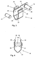
- the fastening system comprises a first pin 16 and a second pin 17, both of which have a diameter of 6 mm.
- the bolt 17 is present as a separate part.
- the bolt 16 is connected via a connecting strip 19 with a securing element 18.
- the securing element 18 comprises two securing surfaces 20, 21, which have a distance from each other which is slightly smaller than the distance between the end faces of the second bolt 17 to each other.
- the securing surfaces 20, 21 are connected to one another via a transverse connection 22.
- the securing surfaces 20, 21 are adjoined by clamping sections 23, 24 whose spacing from each other is less than the distance between the securing surfaces 20, 21 relative to one another. Again beyond the clamping portions 23, 24 close to guide portions 25, 26 whose distance from each other is greater than the distance the clamping portions 23, 24 to each other and are inclined outwardly.
- the bellows bottom 11 is fastened to the bellows body 10 by means of this fastening system, the bellows bottom 11 is first aligned with the bellows body 10 in such a way that the two holes of the strip 13 complement each other with the two holes of the strip 12 to form two aligned bores 14, 15.
- the bolts 16, 17 are inserted into the bores 14, 15, wherein the bolt 16 is rotated so that the securing element 18 faces downward.
- the securing element 18 is pivoted so that the guide portions 25, 26 abut against the lower edge of the bar 12. If the securing element 18 is then pressed further in the direction of the bar 12, the guide sections 25, 26 slide along the bar 12, so that the securing element 18 is spread. The spread is made possible by a slight elasticity of the transverse connection 22. The securing element 18 is further pushed upward until the clamping portions 23, 24 are above the bar 12 and engage behind the bar 12. The locking surfaces 20, 21 are now on the end faces of the bolt 17, so that the bolt 17 can not move out of the bore 15. Through the connecting strip 19, which establishes a rigid connection between the securing element 18 and the bolt 16, the bolt 16 is held firmly in position and can not move out of the bore 14 out.
- the strip 13 of the bellows bottom 11 is then as in the sectional view of Fig. 5 shown firmly with the bar 12 of the bellows body 10 connected.
- the cross-connection 22 can engage around the bar 12, it has a distance from the plane in which the axes of the two bolts 16, 17, which is greater than the diameter of the bolt 17.
- Sections of the bellows material may additionally be connected to a rivet 27.
- the securing element 18 In order to release the connection again, the securing element 18 must be pivoted in the opposite direction, so that the bolt 17 is released again. In order to pivot the securing element 18 downwards, one can engage the guide sections 25, 26 and pull the securing element downwards. Alternatively, you can start with a screwdriver in the recess, which is due to the angled shape of the cross-connection 22 between the cross-connection 22 and the bar 12, and pry the securing element 18 down.
Landscapes
- Engineering & Computer Science (AREA)
- Mechanical Engineering (AREA)
- Life Sciences & Earth Sciences (AREA)
- Wood Science & Technology (AREA)
- Diaphragms And Bellows (AREA)
- Optical Communication System (AREA)
- Materials For Medical Uses (AREA)
- Laminated Bodies (AREA)
- Floor Finish (AREA)
- Joining Of Building Structures In Genera (AREA)
Priority Applications (8)
| Application Number | Priority Date | Filing Date | Title |
|---|---|---|---|
| EP08006343A EP2106984B1 (de) | 2008-03-31 | 2008-03-31 | Faltenbalg |
| AT08006343T ATE475572T1 (de) | 2008-03-31 | 2008-03-31 | Faltenbalg |
| ES08006343T ES2348124T3 (es) | 2008-03-31 | 2008-03-31 | Fuelle de intercomunicación. |
| PT08006343T PT2106984E (pt) | 2008-03-31 | 2008-03-31 | Fole |
| DE502008001032T DE502008001032D1 (de) | 2008-03-31 | 2008-03-31 | Faltenbalg |
| PL08006343T PL2106984T3 (pl) | 2008-03-31 | 2008-03-31 | Osłona harmonijkowa |
| US12/415,614 US7866683B2 (en) | 2008-03-31 | 2009-03-31 | Gangway bellows |
| CA2660971A CA2660971C (en) | 2008-03-31 | 2009-03-31 | Gangway bellows |
Applications Claiming Priority (1)
| Application Number | Priority Date | Filing Date | Title |
|---|---|---|---|
| EP08006343A EP2106984B1 (de) | 2008-03-31 | 2008-03-31 | Faltenbalg |
Publications (2)
| Publication Number | Publication Date |
|---|---|
| EP2106984A1 EP2106984A1 (de) | 2009-10-07 |
| EP2106984B1 true EP2106984B1 (de) | 2010-07-28 |
Family
ID=39710826
Family Applications (1)
| Application Number | Title | Priority Date | Filing Date |
|---|---|---|---|
| EP08006343A Active EP2106984B1 (de) | 2008-03-31 | 2008-03-31 | Faltenbalg |
Country Status (8)
| Country | Link |
|---|---|
| US (1) | US7866683B2 (pl) |
| EP (1) | EP2106984B1 (pl) |
| AT (1) | ATE475572T1 (pl) |
| CA (1) | CA2660971C (pl) |
| DE (1) | DE502008001032D1 (pl) |
| ES (1) | ES2348124T3 (pl) |
| PL (1) | PL2106984T3 (pl) |
| PT (1) | PT2106984E (pl) |
Families Citing this family (5)
| Publication number | Priority date | Publication date | Assignee | Title |
|---|---|---|---|---|
| CN104554307A (zh) * | 2014-12-18 | 2015-04-29 | 南车青岛四方机车车辆股份有限公司 | 动车组车体及其内风挡安装结构 |
| AT15496U1 (de) * | 2016-02-11 | 2017-10-15 | Hübner Gmbh & Co Kg | Mittel zum Sichern einer Verbindung zweier stirnseitig in Umfangsrichtung zusammentreffender Balgelemente eines Balges |
| DE102017102626A1 (de) * | 2017-02-09 | 2018-08-09 | HÜBNER GmbH & Co. KG | Mehrschichtiges Flächengebilde aufweisend zumindest ein Trägergewebe, Übergangselement aufweisend ein derartiges mehrschichtiges Flächengebilde, sowie Fahrzeug, Fluggastbrücke oder -treppe mit einem derartigen Übergangselement |
| IT202000003671A1 (it) | 2020-02-21 | 2021-08-21 | P E I Protezioni Elaborazioni Ind S R L | Dispositivo di fissaggio, gruppo di isolamento e procedimento corrispondenti. |
| SE544961C2 (en) * | 2020-05-11 | 2023-02-07 | Dellner Couplers Ab | Convolute for a bellows for a gangway, bellows for a gangway and multi-car vehicle |
Family Cites Families (17)
| Publication number | Priority date | Publication date | Assignee | Title |
|---|---|---|---|---|
| US2004231A (en) * | 1934-05-18 | 1935-06-11 | George G Wasson | Clip |
| US4798148A (en) * | 1986-06-06 | 1989-01-17 | A.N.F. Industrie | Device for intercommunication between coupled vehicles in which passengers can walk freely, especially railway cars or road vehicles |
| FR2629034B1 (fr) * | 1988-03-25 | 1990-04-20 | Caoutchouc Manuf Plastique | Membrane deformable pour tunnel d'intercirculation entre vehicules successifs ferroviaires ou routiers |
| DE4105449A1 (de) * | 1991-02-21 | 1992-08-27 | Huebner Gummi & Kunststoff | Faltenbalg fuer uebergaenge von gelenkfahrzeugen, halteprofil fuer die befestigung eines solchen faltenbalgs an einem gelenkfahrzeug und bausatz aus einem solchen faltenbalg und einem solchen halteprofil sowie einbauverfahren |
| DE4227126A1 (de) * | 1992-05-07 | 1993-11-11 | Huebner Gummi & Kunststoff | Gelenkverbindung zwischen zwei gelenkig miteinander verbundenen Fahrzeugen |
| DE9413320U1 (de) * | 1994-08-18 | 1994-11-10 | Hübner Gummi- und Kunststoff GmbH, 34123 Kassel | Faltenbalg |
| DE29509204U1 (de) * | 1995-06-03 | 1995-09-28 | Hübner Gummi- und Kunststoff GmbH, 34123 Kassel | Vorrichtung zur Abdeckung der Spurfuge zwischen dem Drehteller des Drehgelenks und dem Falten- oder Wellenbalg eines Gelenkfahrzeugs |
| DE19821083B4 (de) * | 1998-05-12 | 2004-04-15 | Hübner GmbH | Balg eines Übergangs zwischen zwei gelenkig miteinander verbundenen Fahrzeugen oder Fahrzeugteilen |
| DE20020061U1 (de) * | 2000-11-25 | 2001-03-01 | Hübner GmbH, 34123 Kassel | Balg eines Überganges zwischen zwei gelenkig miteinander verbundenen Fahrzeugen |
| DE10238673C1 (de) * | 2002-08-23 | 2003-12-24 | Huebner Gmbh | Falte oder Welle eines Balges eines Überganges zwischen zwei gelenkig miteinander verbundenen Fahrzeugen oder Fahrzeugteilen, z.B. einem Gelenkbus |
| FR2866616A1 (fr) * | 2004-02-25 | 2005-08-26 | Hutchinson | Plancher pour soufflet d'interconnexion entre deux voitures |
| FR2866617B1 (fr) * | 2004-02-25 | 2006-05-12 | Hutchinson | Plancher elastique et couloir d'intercirculation le comprenant |
| ITBO20050031U1 (it) * | 2005-05-31 | 2006-12-01 | P E I Protezione Elaborazionei | Elemento di collegamento per profili di irrigidimento di un soffietto |
| DE102005032218A1 (de) * | 2005-07-09 | 2007-01-11 | Hübner GmbH | Vorrichtung zum Abdecken der Spurfuge (Spurfugenabdeckung) zwischen dem Drehteller und dem Balg eines Übergangs zwischen zwei gelenkig miteinander verbundener Fahrzeugteile |
| DE102006002655B4 (de) * | 2006-01-19 | 2008-03-06 | Hübner GmbH | Balg eines Übergangs zwischen zwei gelenkig miteinander verbundenen Fahrzeugen |
| IT1390797B1 (it) * | 2008-07-31 | 2011-10-19 | Pei Protezioni Elaborazioni | Dispositivo di collegamento tra il soffietto ed il telaio di veicoli articolati. |
| IT1390798B1 (it) * | 2008-07-31 | 2011-10-19 | Pei Protezioni Elaborazioni | Dispositivo di collegamento tra il soffietto ed il telaio di veicoli articolati. |
-
2008
- 2008-03-31 PT PT08006343T patent/PT2106984E/pt unknown
- 2008-03-31 PL PL08006343T patent/PL2106984T3/pl unknown
- 2008-03-31 ES ES08006343T patent/ES2348124T3/es active Active
- 2008-03-31 DE DE502008001032T patent/DE502008001032D1/de active Active
- 2008-03-31 EP EP08006343A patent/EP2106984B1/de active Active
- 2008-03-31 AT AT08006343T patent/ATE475572T1/de active
-
2009
- 2009-03-31 CA CA2660971A patent/CA2660971C/en active Active
- 2009-03-31 US US12/415,614 patent/US7866683B2/en active Active
Also Published As
| Publication number | Publication date |
|---|---|
| CA2660971C (en) | 2014-06-10 |
| US20090243257A1 (en) | 2009-10-01 |
| ATE475572T1 (de) | 2010-08-15 |
| ES2348124T3 (es) | 2010-11-30 |
| EP2106984A1 (de) | 2009-10-07 |
| US7866683B2 (en) | 2011-01-11 |
| PT2106984E (pt) | 2010-09-30 |
| DE502008001032D1 (de) | 2010-09-09 |
| CA2660971A1 (en) | 2009-09-30 |
| PL2106984T3 (pl) | 2011-01-31 |
Similar Documents
| Publication | Publication Date | Title |
|---|---|---|
| DE60212246T2 (de) | Gruppe von zwei Karosserieteilen die Kante an Kante zusammenzufügen sind und Karosserieteil aus einer solchen Bauteilgruppe | |
| DE10318220B4 (de) | Montagestruktur und Montageverfahren für Fahrzeuginnenteile | |
| DE102014005286B3 (de) | Befestigungsvorrichtung, Aufhängevorrichtung und Verfahren zum Montieren einer Aufhängevorrichtung | |
| EP2112055A1 (de) | Luftleitbauteil und Karosserievorbau eines Kraftfahrzeuges | |
| EP3581057A1 (de) | Schnalle, insbesondere gurtschnalle | |
| DE29916465U1 (de) | Tisch-Einheit | |
| EP3566270B1 (de) | Montageplattenanordnung und ein entsprechendes verfahren | |
| EP3001931B1 (de) | Blendenprofilabdeckvorrichtung | |
| DE102016109499A1 (de) | System aus einem Bauteil und einer Befestigungsvorrichtung | |
| DE4229867A1 (de) | Aufbau eines sonnendachs eines selbstfahrenden fahrzeugs und verfahren zur montage desselben | |
| DE102022109073A1 (de) | Befestigungselement | |
| EP2508407B1 (de) | Gerüst, insbesondere für elektrische Einrichtungen in einem Schienenfahrzeug, und Verfahren zur Herstellung des Gerüsts | |
| EP2106984A1 (de) | Faltenbalg | |
| EP3275733B1 (de) | Scheinwerferbefestigungssystem für kraftfahrzeuge und verfahren | |
| EP3529868B1 (de) | Verbindungsanordnung für die verbindung von zwei schaltschrankrahmengestellen | |
| EP2468969A2 (de) | Abdeckvorrichtung für eine Entwässerungsmulde | |
| EP3557084A1 (de) | Verbindungselement zum verbinden von profilelementen | |
| WO2016100992A1 (de) | Verfahren zum verbinden von möbelbeschlagsteilen und möbelbeschlag | |
| DE202014004012U1 (de) | Möbelteil-Abdeckelement | |
| DE2353418A1 (de) | Fassungsvorrichtung | |
| EP3745919B1 (de) | Anordnung | |
| WO2014180457A1 (de) | Befestigungselement zur anbindung von übertragungsmitteln an ein hebelelement | |
| EP4558009B1 (de) | Schubladenseitenwand für eine schublade | |
| DE102020209298A1 (de) | Karosserie für ein Fahrzeug | |
| DE102009026297A1 (de) | Cockpitquerträger mit variablem Lenksäulenneigungswinkel |
Legal Events
| Date | Code | Title | Description |
|---|---|---|---|
| PUAI | Public reference made under article 153(3) epc to a published international application that has entered the european phase |
Free format text: ORIGINAL CODE: 0009012 |
|
| 17P | Request for examination filed |
Effective date: 20081105 |
|
| AK | Designated contracting states |
Kind code of ref document: A1 Designated state(s): AT BE BG CH CY CZ DE DK EE ES FI FR GB GR HR HU IE IS IT LI LT LU LV MC MT NL NO PL PT RO SE SI SK TR |
|
| AX | Request for extension of the european patent |
Extension state: AL BA MK RS |
|
| GRAP | Despatch of communication of intention to grant a patent |
Free format text: ORIGINAL CODE: EPIDOSNIGR1 |
|
| AKX | Designation fees paid |
Designated state(s): AT BE BG CH CY CZ DE DK EE ES FI FR GB GR HR HU IE IS IT LI LT LU LV MC MT NL NO PL PT RO SE SI SK TR |
|
| GRAS | Grant fee paid |
Free format text: ORIGINAL CODE: EPIDOSNIGR3 |
|
| GRAA | (expected) grant |
Free format text: ORIGINAL CODE: 0009210 |
|
| AK | Designated contracting states |
Kind code of ref document: B1 Designated state(s): AT BE BG CH CY CZ DE DK EE ES FI FR GB GR HR HU IE IS IT LI LT LU LV MC MT NL NO PL PT RO SE SI SK TR |
|
| REG | Reference to a national code |
Ref country code: GB Ref legal event code: FG4D Free format text: NOT ENGLISH |
|
| REG | Reference to a national code |
Ref country code: CH Ref legal event code: EP |
|
| REG | Reference to a national code |
Ref country code: IE Ref legal event code: FG4D Free format text: LANGUAGE OF EP DOCUMENT: GERMAN |
|
| REF | Corresponds to: |
Ref document number: 502008001032 Country of ref document: DE Date of ref document: 20100909 Kind code of ref document: P |
|
| REG | Reference to a national code |
Ref country code: PT Ref legal event code: SC4A Free format text: AVAILABILITY OF NATIONAL TRANSLATION Effective date: 20100923 |
|
| REG | Reference to a national code |
Ref country code: NL Ref legal event code: VDEP Effective date: 20100728 |
|
| LTIE | Lt: invalidation of european patent or patent extension |
Effective date: 20100728 |
|
| PG25 | Lapsed in a contracting state [announced via postgrant information from national office to epo] |
Ref country code: LT Free format text: LAPSE BECAUSE OF FAILURE TO SUBMIT A TRANSLATION OF THE DESCRIPTION OR TO PAY THE FEE WITHIN THE PRESCRIBED TIME-LIMIT Effective date: 20100728 Ref country code: FI Free format text: LAPSE BECAUSE OF FAILURE TO SUBMIT A TRANSLATION OF THE DESCRIPTION OR TO PAY THE FEE WITHIN THE PRESCRIBED TIME-LIMIT Effective date: 20100728 Ref country code: NO Free format text: LAPSE BECAUSE OF FAILURE TO SUBMIT A TRANSLATION OF THE DESCRIPTION OR TO PAY THE FEE WITHIN THE PRESCRIBED TIME-LIMIT Effective date: 20101028 Ref country code: NL Free format text: LAPSE BECAUSE OF FAILURE TO SUBMIT A TRANSLATION OF THE DESCRIPTION OR TO PAY THE FEE WITHIN THE PRESCRIBED TIME-LIMIT Effective date: 20100728 |
|
| REG | Reference to a national code |
Ref country code: PL Ref legal event code: T3 |
|
| PG25 | Lapsed in a contracting state [announced via postgrant information from national office to epo] |
Ref country code: HR Free format text: LAPSE BECAUSE OF FAILURE TO SUBMIT A TRANSLATION OF THE DESCRIPTION OR TO PAY THE FEE WITHIN THE PRESCRIBED TIME-LIMIT Effective date: 20100728 Ref country code: BG Free format text: LAPSE BECAUSE OF FAILURE TO SUBMIT A TRANSLATION OF THE DESCRIPTION OR TO PAY THE FEE WITHIN THE PRESCRIBED TIME-LIMIT Effective date: 20101028 Ref country code: SI Free format text: LAPSE BECAUSE OF FAILURE TO SUBMIT A TRANSLATION OF THE DESCRIPTION OR TO PAY THE FEE WITHIN THE PRESCRIBED TIME-LIMIT Effective date: 20100728 Ref country code: CY Free format text: LAPSE BECAUSE OF FAILURE TO SUBMIT A TRANSLATION OF THE DESCRIPTION OR TO PAY THE FEE WITHIN THE PRESCRIBED TIME-LIMIT Effective date: 20100728 Ref country code: IS Free format text: LAPSE BECAUSE OF FAILURE TO SUBMIT A TRANSLATION OF THE DESCRIPTION OR TO PAY THE FEE WITHIN THE PRESCRIBED TIME-LIMIT Effective date: 20101128 |
|
| PG25 | Lapsed in a contracting state [announced via postgrant information from national office to epo] |
Ref country code: SE Free format text: LAPSE BECAUSE OF FAILURE TO SUBMIT A TRANSLATION OF THE DESCRIPTION OR TO PAY THE FEE WITHIN THE PRESCRIBED TIME-LIMIT Effective date: 20100728 Ref country code: LV Free format text: LAPSE BECAUSE OF FAILURE TO SUBMIT A TRANSLATION OF THE DESCRIPTION OR TO PAY THE FEE WITHIN THE PRESCRIBED TIME-LIMIT Effective date: 20100728 |
|
| PG25 | Lapsed in a contracting state [announced via postgrant information from national office to epo] |
Ref country code: DK Free format text: LAPSE BECAUSE OF FAILURE TO SUBMIT A TRANSLATION OF THE DESCRIPTION OR TO PAY THE FEE WITHIN THE PRESCRIBED TIME-LIMIT Effective date: 20100728 |
|
| PG25 | Lapsed in a contracting state [announced via postgrant information from national office to epo] |
Ref country code: IT Free format text: LAPSE BECAUSE OF FAILURE TO SUBMIT A TRANSLATION OF THE DESCRIPTION OR TO PAY THE FEE WITHIN THE PRESCRIBED TIME-LIMIT Effective date: 20100728 Ref country code: EE Free format text: LAPSE BECAUSE OF FAILURE TO SUBMIT A TRANSLATION OF THE DESCRIPTION OR TO PAY THE FEE WITHIN THE PRESCRIBED TIME-LIMIT Effective date: 20100728 Ref country code: SK Free format text: LAPSE BECAUSE OF FAILURE TO SUBMIT A TRANSLATION OF THE DESCRIPTION OR TO PAY THE FEE WITHIN THE PRESCRIBED TIME-LIMIT Effective date: 20100728 Ref country code: RO Free format text: LAPSE BECAUSE OF FAILURE TO SUBMIT A TRANSLATION OF THE DESCRIPTION OR TO PAY THE FEE WITHIN THE PRESCRIBED TIME-LIMIT Effective date: 20100728 Ref country code: CZ Free format text: LAPSE BECAUSE OF FAILURE TO SUBMIT A TRANSLATION OF THE DESCRIPTION OR TO PAY THE FEE WITHIN THE PRESCRIBED TIME-LIMIT Effective date: 20100728 |
|
| PLBE | No opposition filed within time limit |
Free format text: ORIGINAL CODE: 0009261 |
|
| STAA | Information on the status of an ep patent application or granted ep patent |
Free format text: STATUS: NO OPPOSITION FILED WITHIN TIME LIMIT |
|
| 26N | No opposition filed |
Effective date: 20110429 |
|
| REG | Reference to a national code |
Ref country code: DE Ref legal event code: R097 Ref document number: 502008001032 Country of ref document: DE Effective date: 20110429 |
|
| PG25 | Lapsed in a contracting state [announced via postgrant information from national office to epo] |
Ref country code: MC Free format text: LAPSE BECAUSE OF NON-PAYMENT OF DUE FEES Effective date: 20110331 |
|
| PG25 | Lapsed in a contracting state [announced via postgrant information from national office to epo] |
Ref country code: MT Free format text: LAPSE BECAUSE OF FAILURE TO SUBMIT A TRANSLATION OF THE DESCRIPTION OR TO PAY THE FEE WITHIN THE PRESCRIBED TIME-LIMIT Effective date: 20100728 |
|
| REG | Reference to a national code |
Ref country code: CH Ref legal event code: PL |
|
| PG25 | Lapsed in a contracting state [announced via postgrant information from national office to epo] |
Ref country code: LI Free format text: LAPSE BECAUSE OF NON-PAYMENT OF DUE FEES Effective date: 20120331 Ref country code: CH Free format text: LAPSE BECAUSE OF NON-PAYMENT OF DUE FEES Effective date: 20120331 |
|
| PG25 | Lapsed in a contracting state [announced via postgrant information from national office to epo] |
Ref country code: LU Free format text: LAPSE BECAUSE OF NON-PAYMENT OF DUE FEES Effective date: 20110331 |
|
| PG25 | Lapsed in a contracting state [announced via postgrant information from national office to epo] |
Ref country code: TR Free format text: LAPSE BECAUSE OF FAILURE TO SUBMIT A TRANSLATION OF THE DESCRIPTION OR TO PAY THE FEE WITHIN THE PRESCRIBED TIME-LIMIT Effective date: 20100728 |
|
| PG25 | Lapsed in a contracting state [announced via postgrant information from national office to epo] |
Ref country code: HU Free format text: LAPSE BECAUSE OF FAILURE TO SUBMIT A TRANSLATION OF THE DESCRIPTION OR TO PAY THE FEE WITHIN THE PRESCRIBED TIME-LIMIT Effective date: 20100728 |
|
| PG25 | Lapsed in a contracting state [announced via postgrant information from national office to epo] |
Ref country code: GR Free format text: LAPSE BECAUSE OF FAILURE TO SUBMIT A TRANSLATION OF THE DESCRIPTION OR TO PAY THE FEE WITHIN THE PRESCRIBED TIME-LIMIT Effective date: 20100728 |
|
| REG | Reference to a national code |
Ref country code: FR Ref legal event code: PLFP Year of fee payment: 9 |
|
| REG | Reference to a national code |
Ref country code: FR Ref legal event code: PLFP Year of fee payment: 10 |
|
| REG | Reference to a national code |
Ref country code: FR Ref legal event code: PLFP Year of fee payment: 11 |
|
| PGFP | Annual fee paid to national office [announced via postgrant information from national office to epo] |
Ref country code: IE Payment date: 20230320 Year of fee payment: 16 Ref country code: AT Payment date: 20230317 Year of fee payment: 16 |
|
| PGFP | Annual fee paid to national office [announced via postgrant information from national office to epo] |
Ref country code: PT Payment date: 20230324 Year of fee payment: 16 Ref country code: PL Payment date: 20230317 Year of fee payment: 16 Ref country code: GB Payment date: 20230323 Year of fee payment: 16 Ref country code: BE Payment date: 20230321 Year of fee payment: 16 |
|
| PGFP | Annual fee paid to national office [announced via postgrant information from national office to epo] |
Ref country code: ES Payment date: 20230414 Year of fee payment: 16 |
|
| REG | Reference to a national code |
Ref country code: AT Ref legal event code: MM01 Ref document number: 475572 Country of ref document: AT Kind code of ref document: T Effective date: 20240331 |
|
| GBPC | Gb: european patent ceased through non-payment of renewal fee |
Effective date: 20240331 |
|
| REG | Reference to a national code |
Ref country code: BE Ref legal event code: MM Effective date: 20240331 |
|
| PG25 | Lapsed in a contracting state [announced via postgrant information from national office to epo] |
Ref country code: BE Free format text: LAPSE BECAUSE OF NON-PAYMENT OF DUE FEES Effective date: 20240331 |
|
| PG25 | Lapsed in a contracting state [announced via postgrant information from national office to epo] |
Ref country code: GB Free format text: LAPSE BECAUSE OF NON-PAYMENT OF DUE FEES Effective date: 20240331 |
|
| PG25 | Lapsed in a contracting state [announced via postgrant information from national office to epo] |
Ref country code: AT Free format text: LAPSE BECAUSE OF NON-PAYMENT OF DUE FEES Effective date: 20240331 |
|
| PG25 | Lapsed in a contracting state [announced via postgrant information from national office to epo] |
Ref country code: IE Free format text: LAPSE BECAUSE OF NON-PAYMENT OF DUE FEES Effective date: 20240331 |
|
| PG25 | Lapsed in a contracting state [announced via postgrant information from national office to epo] |
Ref country code: IE Free format text: LAPSE BECAUSE OF NON-PAYMENT OF DUE FEES Effective date: 20240331 Ref country code: GB Free format text: LAPSE BECAUSE OF NON-PAYMENT OF DUE FEES Effective date: 20240331 Ref country code: BE Free format text: LAPSE BECAUSE OF NON-PAYMENT OF DUE FEES Effective date: 20240331 Ref country code: AT Free format text: LAPSE BECAUSE OF NON-PAYMENT OF DUE FEES Effective date: 20240331 |
|
| PG25 | Lapsed in a contracting state [announced via postgrant information from national office to epo] |
Ref country code: PL Free format text: LAPSE BECAUSE OF NON-PAYMENT OF DUE FEES Effective date: 20240331 |
|
| REG | Reference to a national code |
Ref country code: ES Ref legal event code: FD2A Effective date: 20250506 |
|
| PG25 | Lapsed in a contracting state [announced via postgrant information from national office to epo] |
Ref country code: ES Free format text: LAPSE BECAUSE OF NON-PAYMENT OF DUE FEES Effective date: 20240401 |
|
| PG25 | Lapsed in a contracting state [announced via postgrant information from national office to epo] |
Ref country code: PT Free format text: LAPSE BECAUSE OF NON-PAYMENT OF DUE FEES Effective date: 20240331 |
|
| PGFP | Annual fee paid to national office [announced via postgrant information from national office to epo] |
Ref country code: DE Payment date: 20260320 Year of fee payment: 19 |
|
| PGFP | Annual fee paid to national office [announced via postgrant information from national office to epo] |
Ref country code: FR Payment date: 20260324 Year of fee payment: 19 |