EP2106935B1 - Fahrzeug - Google Patents
Fahrzeug Download PDFInfo
- Publication number
- EP2106935B1 EP2106935B1 EP09153906A EP09153906A EP2106935B1 EP 2106935 B1 EP2106935 B1 EP 2106935B1 EP 09153906 A EP09153906 A EP 09153906A EP 09153906 A EP09153906 A EP 09153906A EP 2106935 B1 EP2106935 B1 EP 2106935B1
- Authority
- EP
- European Patent Office
- Prior art keywords
- pair
- axle
- connecting rod
- suspension
- rod mounts
- Prior art date
- Legal status (The legal status is an assumption and is not a legal conclusion. Google has not performed a legal analysis and makes no representation as to the accuracy of the status listed.)
- Not-in-force
Links
Images


Classifications
-
- B—PERFORMING OPERATIONS; TRANSPORTING
- B60—VEHICLES IN GENERAL
- B60G—VEHICLE SUSPENSION ARRANGEMENTS
- B60G9/00—Resilient suspensions of a rigid axle or axle housing for two or more wheels
- B60G9/02—Resilient suspensions of a rigid axle or axle housing for two or more wheels the axle or housing being pivotally mounted on the vehicle, e.g. the pivotal axis being parallel to the longitudinal axis of the vehicle
-
- B—PERFORMING OPERATIONS; TRANSPORTING
- B60—VEHICLES IN GENERAL
- B60G—VEHICLE SUSPENSION ARRANGEMENTS
- B60G2200/00—Indexing codes relating to suspension types
- B60G2200/30—Rigid axle suspensions
- B60G2200/314—Rigid axle suspensions with longitudinally arranged arms articulated on the axle
-
- B—PERFORMING OPERATIONS; TRANSPORTING
- B60—VEHICLES IN GENERAL
- B60G—VEHICLE SUSPENSION ARRANGEMENTS
- B60G2202/00—Indexing codes relating to the type of spring, damper or actuator
- B60G2202/10—Type of spring
- B60G2202/15—Fluid spring
- B60G2202/152—Pneumatic spring
-
- B—PERFORMING OPERATIONS; TRANSPORTING
- B60—VEHICLES IN GENERAL
- B60G—VEHICLE SUSPENSION ARRANGEMENTS
- B60G2202/00—Indexing codes relating to the type of spring, damper or actuator
- B60G2202/20—Type of damper
- B60G2202/24—Fluid damper
-
- B—PERFORMING OPERATIONS; TRANSPORTING
- B60—VEHICLES IN GENERAL
- B60G—VEHICLE SUSPENSION ARRANGEMENTS
- B60G2204/00—Indexing codes related to suspensions per se or to auxiliary parts
- B60G2204/10—Mounting of suspension elements
- B60G2204/14—Mounting of suspension arms
-
- B—PERFORMING OPERATIONS; TRANSPORTING
- B60—VEHICLES IN GENERAL
- B60G—VEHICLE SUSPENSION ARRANGEMENTS
- B60G2206/00—Indexing codes related to the manufacturing of suspensions: constructional features, the materials used, procedures or tools
- B60G2206/01—Constructional features of suspension elements, e.g. arms, dampers, springs
- B60G2206/60—Subframe construction
-
- B—PERFORMING OPERATIONS; TRANSPORTING
- B60—VEHICLES IN GENERAL
- B60G—VEHICLE SUSPENSION ARRANGEMENTS
- B60G2300/00—Indexing codes relating to the type of vehicle
- B60G2300/08—Agricultural vehicles
- B60G2300/083—Boom carrying vehicles, e.g. for crop spraying
Definitions
- the present invention relates to a vehicle including a main frame, an axle extending beneath the main frame and a suspension coupled between the axle and the frame for allowing up and down movement of the axle relative to the frame.
- One known self-propelled sprayer is provided with a suspension arrangement having each of four drive wheels of the sprayer suspended independently, one each at opposite ends of front and rear axles that are fixed to the main frame of the sprayer.
- the suspension for each of the wheels includes a large complicated, machined casting fixed to one end of an associated axle and which works together with expensive chrome spindles which telescope within upright sleeves defined by the casting so as to permit relative motion between the wheel and the axle.
- Another known self-propelled sprayer avoids the costs associated with the machined casting and chrome spindles by suspending the axles by the provision of a pair of connecting rods coupled between the vehicle main frame and each of opposite ends of the axle, and by providing a fifth connecting rod that serves as a lateral stabilizer bar.
- This suspension design suffers from the drawback that the axle swings in an arc about the attachment points of the lateral stabilizer bar creating tracking issues as the suspension goes up and down.
- the EP 1 769 950 discloses an arrangement for a suspension linkage between a frame and an axle of a vehicle.
- the linkage comprises an arrangement of a pair of mounting rods, which are arranged in a special way in order to fulfill the requirements for a road sweeper machine.
- the proposed arrangement is directed to the use in a road sweeper machine and may not fulfill the requirements for an agricultural machine.
- an object of the invention is to provide a vehicle of above mentioned type with a wheel suspension which overcomes the drawbacks associated with the prior art suspensions.
- a work vehicle of the above mentioned type comprises a suspension comprising at least one pair of connecting rods coupled between a middle region of said axle and said main frame, with said pair of connecting rods, when viewed from the top, defining an X, and when viewed from the side, being parallel with each other.
- a vehicle provides a relatively simple vehicle axle suspension including suspension rods arranged in a manner for resulting in the opposite ends of the axle undergoing near vertical up and down motion as the vehicle travels over uneven ground.
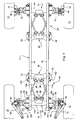
- a chassis 10 of a high clearance agricultural vehicle such as a self-propelled agricultural field sprayer, including a main frame 11 supported on a front pair of driven, steerable ground wheels 12 and a rear pair of driven, non-steerable ground wheels 13.
- the main frame 11 comprises transversely spaced, right- and left-hand, fore-and-aft extending parallel beams 14 and 16, respectively.
- the beams 14 and 16 are fixed relative to each other by cross members in the form of front and rear, generally V-shaped suspension rod mounting brackets 18 and 20, respectively.
- the front bracket 18 is spaced to the rear from front ends of the beams 14 and 16 and has opposite vertical ends 22 and 24, respectively engaged with, and secured, as by bolts (not shown), against outer faces of the beams.
- the rear bracket 20 is spaced forwardly from rear ends of the beams 14 and 16 and has opposite vertical ends 26 and 28 respectively engaged with, and secured, as by bolts (not shown) against, the outer faces of the beams 14 and 16.
- front and rear axles 30 and 32 Extending beneath each of front and rear end regions of, and disposed crosswise relative to, the parallel beams 14 and 16 are front and rear axles 30 and 32, respectively.
- the front axle 30 includes a main central section 34 defined by a tube having a square cross section.
- right and left spindle housings, or drop knees 36 and 38 Joined in depending relationship to opposite ends of the central section 34 are right and left spindle housings, or drop knees 36 and 38, respectively, which are each inclined upwardly and inwardly at a relatively small angle to vertical.
- right and left steering cylinder mounting arms 40 and 42 Fixed to, and respectively projecting forwardly from, upper end regions of the drop knees 36 and 38 are right and left steering cylinder mounting arms 40 and 42.
- the rear axle 32 includes a main central section 44 defined by a tube having a square cross section. Joined in depending relationship to opposite ends of the central section 44 are right and left drop knees or spindle housings 46 and 48, respectively, which are each inclined upwardly and inwardly at a relatively small angle to vertical.
- Right and left hand front spindles are respectively mounted for oscillating in the drop knees 36 and 38.
- Upper ends of the spindles 50 and 52 project from tops of the drop knees 36 and 38, and are respectively coupled, as by cap screws 50 and 52,to right and left steering arms 54 and 56.
- wheel support and motor housings 58 and 60 Formed integrally with the bottom ends of the spindles are wheel support and motor housings 58 and 60, with a hydraulic wheel motor 62 being bolted to a mounting surface 64 of each of the housings 58 and 60 and being coupled, in a manner not shown, for driving the front wheels 12.
- a right steering cylinder 68 is coupled between the right mounting arm 40 and the right steering arm 54, while a left steering cylinder 70 is coupled between the left mounting arm 42 and the left steering arm 56.
- right and left rear spindles 72 and 74 mounted for oscillating in the drop knees 46 and 48 of the rear axle 32.
- Formed integrally with a bottom end of the spindles 72 and 74 are right and left wheel support and motor housings 76 and 78.
- a hydraulic drive motor 80 is bolted to an outwardly facing mounting surface (not shown) of each of the wheel support and motor housings 76 and 78, and is coupled for driving an associated one of the non-steerable rear wheels 13.
- the front and rear axles 30 and 32 are respectively suspended from the main frame 11 by substantially identical front and rear suspension arrangements 84 and 86, which are mirror images of each other, with only the front suspension arrangement 84 being shown and described in detail for the sake of brevity.
- the front suspension arrangement 84 comprises a middle suspension rod connection bracket joined to, and projecting rearwardly from, an upper central location of the middle section 34 of the front axle 30 and including a pair of right and left, upper suspension rod mounts 88 and 90, respectively.
- Located approximately midway between a right end of the axle middle section 34 and the right upper mount 88 is a right, lower suspension rod connection bracket including a right, lower suspension rod mount 92.
- a left, lower suspension rod mount 94 located approximately midway between a left end of the axle middle section 34 and the left upper mount 90.
- the distance between the upper mounts 88 and 90 is substantially equal to the distance between the right upper mount 88 and the right lower mount 92, and to the distance between the left upper mount 90 and the left lower mount 94.
- a pair of right and left lower suspension rod connection mounts 96 and 98 Joined to and projecting forwardly from a lower middle location of the front suspension rod mounting bracket 18 is a pair of right and left lower suspension rod connection mounts 96 and 98, respectively. Respectively joined to, and projecting forwardly from, upper right and left end locations of the bracket 18 are an upper pair of suspension rod connection mounts 100 and 102. As viewed from the top in Fig. 1 , the spacing between the lower mounts 96 and 98 is substantially equal to the spacing between the right lower mount 96 and the right upper mount 100, and the spacing between the left lower mount 98 and the left upper mount 102.
- An upper pair of right and left suspension rods 104 and 106 have forward ends respectively coupled to the upper pair of mounts 88 and 90, and have rear ends respectively coupled to the upper pair of mounts 100 and 102.
- a lower pair of right and left suspension rods 108 and 110 have forward ends respectively coupled to the lower right and left suspension rod connection mounts 92 and 94, and have rear ends respectively coupled to the lower right and left suspension mounts 96 and 98.
- the upper pair of suspension rods 104 and 106 are parallel to the lower pair of suspension rods 108 and 110.
- the axle 30 and attached wheels 12 travel substantially vertically during travel over uneven ground.
- the right set of upper and lower suspension rods 104 and 108 are arranged relative to each other so as to form an X, with the left set of upper and lower suspension rods 106 and 110 being arranged in a similar fashion.
- Up and down motion of the front axle 30 is cushioned by right and left airbags 112 and 114, having upper ends respectively coupled to right and left horizontal mounting plates 116 and 118 respectively fixed to and projecting outwardly from forward end regions of outer faces of the right and left beams 14 and 16; and having lower ends respectively coupled to right and left airbag connection by left and right airbag connection brackets (only left hand bracket 122 is visible) respectively projecting upwardly from right and left end regions of the central section 34 of the front axle 30.
- right and left airbags 112 and 114 having upper ends respectively coupled to right and left horizontal mounting plates 116 and 118 respectively fixed to and projecting outwardly from forward end regions of outer faces of the right and left beams 14 and 16; and having lower ends respectively coupled to right and left airbag connection by left and right airbag connection brackets (only left hand bracket 122 is visible) respectively projecting upwardly from right and left end regions of the central section 34 of the front axle 30.
- Up and down motion of the rear axle 32 is similarly cushioned by right and left rear airbags and right and left rear shock absorbers, with the drawings having only a clear showing of a left airbag 134 and a left shock absorber 136 (see Fig. 2 ).
- the suspended front and rear axles 30 and 32 permit vertical movement of the axles making it unnecessary to provide expensive chrome spindles as are needed with the fixed axle design disclosed in the aforementioned U.S. Patent No. 7,168,717 .
- a substantially straight line or vertical up and down movement of the axle occurs which eliminates the arc motion generated from lateral stablilizer bars used in prior art suspensions, thus eliminating tracking issues that occur when the axle swings in an arc about the attachment points of the lateral stabilizer bar.
Landscapes
- Engineering & Computer Science (AREA)
- Mechanical Engineering (AREA)
- Vehicle Body Suspensions (AREA)
- Catching Or Destruction (AREA)
Claims (1)
- Fahrzeug mit einem Hauptrahmen (11), einer sich unter dem Hauptrahmen (11) erstreckenden Achse (30) und einer zwischen der Achse (30) und dem Hauptrahmen (11) gekoppelten Aufhängung, um eine Auf- und Abbewegung der Achse (30) bezüglich des Hauptrahmens (11) zu gestatten, wobei die Aufhängung Folgendes umfasst: ein erstes oberes Paar (88, 90) und ein erstes unteres Paar (92, 94) Verbindungsstangenhalterungen, die an der Achse (30) befestigt sind, wobei das obere Paar (88, 90) von oben gesehen zwischen gegenüberliegenden Enden der Achse (30) zentriert und zwischen dem unteren Paar (92, 94) Verbindungsstangenhalterungen angeordnet ist, ein zweites oberes Paar (100, 102) und ein zweites unteres Paar (96, 98) Verbindungsstangenhalterungen, die am Hauptrahmen (11) in Längsrichtung von der Achse (11) beabstandet befestigt sind, wobei das zweite untere Paar (96, 98) Verbindungsstangenhalterungen von oben gesehen zwischen dem zweiten oberen Paar (100, 102) Verbindungsstangenhalterungen angeordnet ist, ein oberes Paar Verbindungsstangen (104, 106) mit ersten Enden, die jeweils an eine und eine andere des ersten oberen Paars (88, 90) Verbindungsstangenhalterungen gekoppelt sind, und mit zweiten Enden, die jeweils an eine und eine andere des zweiten oberen Paars (100, 102) Verbindungsstangenhalterungen gekoppelt sind, und ein Paar unterer Verbindungsstangen (108, 110) mit ersten Enden, die jeweils an eine und eine andere des ersten unteren Paars (92, 94) Verbindungsstangenhalterungen gekoppelt sind, und mit zweiten Enden, die jeweils an eine und eine andere des zweiten unteren Paars (96, 98) Verbindungsstangenhalterungen gekoppelt sind, wobei das erste und das zweite obere Paar (88, 90; 100, 102) Verbindungsstangenhalterungen bezüglich des ersten und des zweiten unteren Paars (92, 94; 96, 98) Verbindungsstangenhalterungen so angeordnet sind, dass sich das obere Paar Verbindungsstangen (104, 106) von der Seite gesehen parallel zu dem unteren Paar Verbindungsstangen (108, 110) erstreckt und eine des Paars oberer Verbindungsstangen (104, 106) von oben gesehen mit einer des Paars unterer Verbindungsstangen (108, 110) zusammenwirkt, so dass ein X gebildet wird, und eine andere des Paars oberer Verbindungsstangen (104, 106) mit einer anderen des Paars unterer Verbindungsstangen (108, 110) zusammenwirkt, so dass ein X gebildet wird.
Applications Claiming Priority (1)
| Application Number | Priority Date | Filing Date | Title |
|---|---|---|---|
| US12/045,107 US7938415B2 (en) | 2008-03-10 | 2008-03-10 | Suspended axle for sprayer |
Publications (2)
| Publication Number | Publication Date |
|---|---|
| EP2106935A1 EP2106935A1 (de) | 2009-10-07 |
| EP2106935B1 true EP2106935B1 (de) | 2011-09-21 |
Family
ID=40711710
Family Applications (1)
| Application Number | Title | Priority Date | Filing Date |
|---|---|---|---|
| EP09153906A Not-in-force EP2106935B1 (de) | 2008-03-10 | 2009-02-27 | Fahrzeug |
Country Status (7)
| Country | Link |
|---|---|
| US (1) | US7938415B2 (de) |
| EP (1) | EP2106935B1 (de) |
| AR (1) | AR070979A1 (de) |
| AU (1) | AU2009200810B2 (de) |
| BR (1) | BRPI0900698B8 (de) |
| CA (1) | CA2655157A1 (de) |
| RU (1) | RU2488267C2 (de) |
Families Citing this family (15)
| Publication number | Priority date | Publication date | Assignee | Title |
|---|---|---|---|---|
| US8534686B1 (en) | 2010-12-30 | 2013-09-17 | Agco Corporation | Independent strut suspension |
| GB2507085B (en) * | 2012-10-18 | 2018-05-23 | Househam Sprayers Ltd | Agricultural sprayer |
| DE102013200694A1 (de) * | 2013-01-17 | 2014-07-17 | Bayerische Motoren Werke Aktiengesellschaft | Starrachse als nicht angetriebene Hinterachse eines Kraftfahrzeugs |
| US9578868B2 (en) * | 2013-07-30 | 2017-02-28 | Winfield Solutions, Llc | High clearance adjustable sprayer |
| US9296273B2 (en) | 2013-10-14 | 2016-03-29 | Agco Corporation | Machine suspension and height adjustment |
| US9180735B2 (en) | 2013-12-02 | 2015-11-10 | Hendrickson Usa, L.L.C. | V-rod attachment assembly for vehicle suspension |
| US9457634B2 (en) * | 2014-09-16 | 2016-10-04 | Agco Corporation | Progressive rate suspension for agricultural vehicle |
| CN105021225B (zh) * | 2015-07-08 | 2017-07-14 | 江苏大学 | 一种温室智能移动检测平台 |
| US10967695B2 (en) * | 2018-03-02 | 2021-04-06 | Blueline Mfg., Co. | Steerable suspension system |
| CN111937833B (zh) * | 2019-05-17 | 2024-07-19 | 西北农林科技大学 | 一种纵向摇摆式高地隙喷雾机底盘 |
| US11364757B2 (en) * | 2019-06-28 | 2022-06-21 | Ree Automotive Ltd | Device and method for double-arm suspension and in-wheel steering |
| EP4096942A4 (de) | 2020-01-28 | 2024-04-17 | Ree Automotive Ltd | Radaufhängung mit aussermittigem arm |
| US11827073B2 (en) | 2020-12-21 | 2023-11-28 | Oshkosh Corporation | Four bar linkage and air spring suspension system |
| US20220305857A1 (en) * | 2021-03-24 | 2022-09-29 | Mf Ip Holding, Llc | Suspension system for a vehicle and method of adjusting rear control arm geometry for same |
| US12441143B2 (en) * | 2023-11-13 | 2025-10-14 | Caterpillar Inc. | Multi-link front suspension for an underground articulated dump truck |
Family Cites Families (16)
| Publication number | Priority date | Publication date | Assignee | Title |
|---|---|---|---|---|
| US2746766A (en) * | 1950-06-13 | 1956-05-22 | Daimler Benz Ag | Suspension of a rigid axle, particularly for motor vehicles |
| SU984897A1 (ru) * | 1981-02-18 | 1982-12-30 | Ташкентский Автомобильно-Дорожный Институт | Подвеска транспортного средства |
| CA1167878A (en) * | 1981-09-02 | 1984-05-22 | Wallace G. Chalmers | Vehicle suspension incorporating cross-over links |
| DE4338651A1 (de) | 1993-11-12 | 1995-03-09 | Daimler Benz Ag | Aufhängung für eine Starrachse eines Fahrzeuges, insbesondere eines Lastkraftwagens oder Omnibusses |
| US5458359A (en) * | 1994-08-08 | 1995-10-17 | Brandt; Larry A. | Missing link swivel for four-link rigid axle suspensions |
| JP3240859B2 (ja) | 1994-12-09 | 2001-12-25 | 三菱自動車工業株式会社 | ショックアブソーバの取付け構造 |
| EP0728601B1 (de) | 1995-02-25 | 1999-10-27 | MAN Nutzfahrzeuge Aktiengesellschaft | Nichtangetriebende Vorder-, Vor- oder Nachlaufachse eines Nutzfahrzeuges, insbesondere Lastkraftwagen oder Omnibus |
| US6042131A (en) * | 1997-12-04 | 2000-03-28 | Bailey; Joseph Allen | Vehicle rear suspension system |
| SE511126C2 (sv) * | 1997-12-30 | 1999-08-09 | Volvo Lastvagnar Ab | V-stagsfäste för fordon |
| US6270282B1 (en) * | 1999-07-06 | 2001-08-07 | Denso Corporation | Torque rod apex mount |
| US6209896B1 (en) * | 1999-09-28 | 2001-04-03 | Meritor Heavy Vehicle Systems Limited | Vehicle suspension attachment assemblies |
| US6666474B2 (en) * | 2002-05-17 | 2003-12-23 | Meritor Heavy Vehicle Technology Llc | Semi-balanced tandem suspension |
| FR2842462B1 (fr) | 2002-07-16 | 2007-01-19 | Irisbus France | Suspension pour essieu rigide de vehicule et vehicule correspondant |
| US7168717B2 (en) | 2005-01-28 | 2007-01-30 | Deere & Company | High clearance vehicle suspension with twin spindles for transferring steering torque |
| EP2098387B1 (de) | 2005-09-28 | 2012-04-18 | Mathieu | Reinigungsfahrzeug |
| US20070138755A1 (en) * | 2005-12-16 | 2007-06-21 | Copsey Charles R | Hybrid-response for suspension system |
-
2008
- 2008-03-10 US US12/045,107 patent/US7938415B2/en active Active
-
2009
- 2009-02-24 CA CA002655157A patent/CA2655157A1/en not_active Abandoned
- 2009-02-25 RU RU2009106611/13A patent/RU2488267C2/ru not_active IP Right Cessation
- 2009-02-27 AU AU2009200810A patent/AU2009200810B2/en not_active Ceased
- 2009-02-27 EP EP09153906A patent/EP2106935B1/de not_active Not-in-force
- 2009-02-27 BR BRPI0900698A patent/BRPI0900698B8/pt active IP Right Grant
- 2009-03-09 AR ARP090100839A patent/AR070979A1/es unknown
Also Published As
| Publication number | Publication date |
|---|---|
| AU2009200810A1 (en) | 2009-09-24 |
| AU2009200810B2 (en) | 2014-07-31 |
| US20090224501A1 (en) | 2009-09-10 |
| CA2655157A1 (en) | 2009-09-10 |
| RU2009106611A (ru) | 2010-08-27 |
| BRPI0900698B8 (pt) | 2020-10-20 |
| RU2488267C2 (ru) | 2013-07-27 |
| US7938415B2 (en) | 2011-05-10 |
| BRPI0900698A2 (pt) | 2010-01-19 |
| AR070979A1 (es) | 2010-05-19 |
| EP2106935A1 (de) | 2009-10-07 |
| BRPI0900698B1 (pt) | 2020-09-29 |
Similar Documents
| Publication | Publication Date | Title |
|---|---|---|
| US7938415B2 (en) | Suspended axle for sprayer | |
| US7048286B2 (en) | Rear axle of a passenger vehicle with five individual links | |
| ES2749677T3 (es) | Estructura de parte delantera de vehículo adecuada para vehículos pequeños | |
| US8746713B2 (en) | Wheel suspension for motor vehicles | |
| RU2412067C2 (ru) | Подвеска колеса для передней оси автомобиля | |
| US7270341B2 (en) | Vehicle suspension with improved radius arm to axle attachment | |
| CA2657101A1 (en) | Front wheel suspension structure for saddle-type vehicle, and vehicle incorporating same | |
| CN203854440U (zh) | 一种适用于轻型卡车的独立悬架 | |
| GB2276594A (en) | Subframe and subframe assembly | |
| US20090026724A1 (en) | Vehicle suspension apparatus | |
| FI110999B (fi) | Akseliaggregaatti | |
| RU2712399C2 (ru) | Пневматическая подвеска оси для задней оси транспортного средства | |
| EP1789268B1 (de) | Radaufhängung | |
| CA2886686C (en) | Suspension system for a flexible frame vehicle | |
| CN1836965B (zh) | 踏板式车辆的车架构造 | |
| US4773661A (en) | Front fenders for four wheeled buggy operated by driver in sitting posture | |
| EP1910108B1 (de) | Einzelradaufhängung | |
| CN106467135B (zh) | 用于车桥的副车架 | |
| CN113086038B (zh) | 一种避震结构及应用其的悬挂机构以及履带车辆底盘 | |
| GB2342902A (en) | Vehicle suspensions | |
| WO2023208764A1 (en) | Three-wheeled motorcycle with a radar device placed between the front wheels | |
| US4070037A (en) | Suspension for vehicles | |
| KR100962191B1 (ko) | 승용 프레임 차량에 채용된 프레임 크로스맴버 구조 | |
| KR100962202B1 (ko) | 멀티링크타입의 후륜 현가장치 | |
| JPH0248274A (ja) | 車両の後輪操舵装置 |
Legal Events
| Date | Code | Title | Description |
|---|---|---|---|
| PUAI | Public reference made under article 153(3) epc to a published international application that has entered the european phase |
Free format text: ORIGINAL CODE: 0009012 |
|
| AK | Designated contracting states |
Kind code of ref document: A1 Designated state(s): AT BE BG CH CY CZ DE DK EE ES FI FR GB GR HR HU IE IS IT LI LT LU LV MC MK MT NL NO PL PT RO SE SI SK TR |
|
| AX | Request for extension of the european patent |
Extension state: AL BA RS |
|
| 17P | Request for examination filed |
Effective date: 20100407 |
|
| 17Q | First examination report despatched |
Effective date: 20100519 |
|
| AKX | Designation fees paid |
Designated state(s): DE FR GB NL |
|
| GRAP | Despatch of communication of intention to grant a patent |
Free format text: ORIGINAL CODE: EPIDOSNIGR1 |
|
| GRAS | Grant fee paid |
Free format text: ORIGINAL CODE: EPIDOSNIGR3 |
|
| GRAA | (expected) grant |
Free format text: ORIGINAL CODE: 0009210 |
|
| AK | Designated contracting states |
Kind code of ref document: B1 Designated state(s): DE FR GB NL |
|
| REG | Reference to a national code |
Ref country code: GB Ref legal event code: FG4D |
|
| REG | Reference to a national code |
Ref country code: DE Ref legal event code: R096 Ref document number: 602009002642 Country of ref document: DE Effective date: 20111201 |
|
| REG | Reference to a national code |
Ref country code: NL Ref legal event code: T3 |
|
| PLBE | No opposition filed within time limit |
Free format text: ORIGINAL CODE: 0009261 |
|
| STAA | Information on the status of an ep patent application or granted ep patent |
Free format text: STATUS: NO OPPOSITION FILED WITHIN TIME LIMIT |
|
| 26N | No opposition filed |
Effective date: 20120622 |
|
| REG | Reference to a national code |
Ref country code: DE Ref legal event code: R097 Ref document number: 602009002642 Country of ref document: DE Effective date: 20120622 |
|
| PGFP | Annual fee paid to national office [announced via postgrant information from national office to epo] |
Ref country code: NL Payment date: 20140226 Year of fee payment: 6 |
|
| PGFP | Annual fee paid to national office [announced via postgrant information from national office to epo] |
Ref country code: GB Payment date: 20140227 Year of fee payment: 6 |
|
| REG | Reference to a national code |
Ref country code: NL Ref legal event code: V1 Effective date: 20150901 |
|
| PG25 | Lapsed in a contracting state [announced via postgrant information from national office to epo] |
Ref country code: NL Free format text: LAPSE BECAUSE OF NON-PAYMENT OF DUE FEES Effective date: 20150901 |
|
| GBPC | Gb: european patent ceased through non-payment of renewal fee |
Effective date: 20150227 |
|
| PG25 | Lapsed in a contracting state [announced via postgrant information from national office to epo] |
Ref country code: GB Free format text: LAPSE BECAUSE OF NON-PAYMENT OF DUE FEES Effective date: 20150227 |
|
| REG | Reference to a national code |
Ref country code: FR Ref legal event code: PLFP Year of fee payment: 8 |
|
| REG | Reference to a national code |
Ref country code: FR Ref legal event code: PLFP Year of fee payment: 9 |
|
| REG | Reference to a national code |
Ref country code: FR Ref legal event code: PLFP Year of fee payment: 10 |
|
| PGFP | Annual fee paid to national office [announced via postgrant information from national office to epo] |
Ref country code: DE Payment date: 20240119 Year of fee payment: 16 |
|
| PGFP | Annual fee paid to national office [announced via postgrant information from national office to epo] |
Ref country code: FR Payment date: 20240226 Year of fee payment: 16 |
|
| REG | Reference to a national code |
Ref country code: DE Ref legal event code: R119 Ref document number: 602009002642 Country of ref document: DE |
|
| PG25 | Lapsed in a contracting state [announced via postgrant information from national office to epo] |
Ref country code: DE Free format text: LAPSE BECAUSE OF NON-PAYMENT OF DUE FEES Effective date: 20250902 |
|
| PG25 | Lapsed in a contracting state [announced via postgrant information from national office to epo] |
Ref country code: FR Free format text: LAPSE BECAUSE OF NON-PAYMENT OF DUE FEES Effective date: 20250228 |