EP2106356B1 - Dispositif de palier pour le montage en rotation decouple en oscillation d'un arbre intermediaire sur le bloc-moteur d'un vehicule a moteur et procede pour le montage en rotation decouple en oscillation d'un arbre intermediaire sur le bloc-moteur d'un vehicule - Google Patents
Dispositif de palier pour le montage en rotation decouple en oscillation d'un arbre intermediaire sur le bloc-moteur d'un vehicule a moteur et procede pour le montage en rotation decouple en oscillation d'un arbre intermediaire sur le bloc-moteur d'un vehicule Download PDFInfo
- Publication number
- EP2106356B1 EP2106356B1 EP08709221.9A EP08709221A EP2106356B1 EP 2106356 B1 EP2106356 B1 EP 2106356B1 EP 08709221 A EP08709221 A EP 08709221A EP 2106356 B1 EP2106356 B1 EP 2106356B1
- Authority
- EP
- European Patent Office
- Prior art keywords
- bearing
- bearing housing
- engine block
- motor vehicle
- intermediate shaft
- Prior art date
- Legal status (The legal status is an assumption and is not a legal conclusion. Google has not performed a legal analysis and makes no representation as to the accuracy of the status listed.)
- Active
Links
- 238000000034 method Methods 0.000 title claims description 12
- 238000013016 damping Methods 0.000 claims description 56
- 230000033001 locomotion Effects 0.000 claims description 7
- 238000005266 casting Methods 0.000 claims description 3
- 239000007769 metal material Substances 0.000 claims description 2
- 238000003860 storage Methods 0.000 description 16
- 230000003534 oscillatory effect Effects 0.000 description 11
- 238000013459 approach Methods 0.000 description 6
- 238000010276 construction Methods 0.000 description 5
- 238000013461 design Methods 0.000 description 5
- 238000002485 combustion reaction Methods 0.000 description 4
- 230000005540 biological transmission Effects 0.000 description 3
- 230000000694 effects Effects 0.000 description 3
- 230000005284 excitation Effects 0.000 description 3
- 238000004519 manufacturing process Methods 0.000 description 3
- 230000001133 acceleration Effects 0.000 description 2
- 230000006835 compression Effects 0.000 description 2
- 238000007906 compression Methods 0.000 description 2
- 239000013013 elastic material Substances 0.000 description 2
- 238000005495 investment casting Methods 0.000 description 2
- 239000000463 material Substances 0.000 description 2
- 239000000725 suspension Substances 0.000 description 2
- 229910001208 Crucible steel Inorganic materials 0.000 description 1
- 229910000831 Steel Inorganic materials 0.000 description 1
- XAGFODPZIPBFFR-UHFFFAOYSA-N aluminium Chemical compound [Al] XAGFODPZIPBFFR-UHFFFAOYSA-N 0.000 description 1
- 229910052782 aluminium Inorganic materials 0.000 description 1
- 239000011248 coating agent Substances 0.000 description 1
- 238000000576 coating method Methods 0.000 description 1
- 239000012530 fluid Substances 0.000 description 1
- 239000000446 fuel Substances 0.000 description 1
- 239000012535 impurity Substances 0.000 description 1
- 238000003780 insertion Methods 0.000 description 1
- 230000037431 insertion Effects 0.000 description 1
- 238000003754 machining Methods 0.000 description 1
- 239000010705 motor oil Substances 0.000 description 1
- 231100000989 no adverse effect Toxicity 0.000 description 1
- 239000003921 oil Substances 0.000 description 1
- 230000008447 perception Effects 0.000 description 1
- 230000002093 peripheral effect Effects 0.000 description 1
- 238000012545 processing Methods 0.000 description 1
- 238000007493 shaping process Methods 0.000 description 1
- 238000004904 shortening Methods 0.000 description 1
- 238000001228 spectrum Methods 0.000 description 1
- 239000010959 steel Substances 0.000 description 1
- 238000004073 vulcanization Methods 0.000 description 1
- 239000004636 vulcanized rubber Substances 0.000 description 1
Images


Classifications
-
- F—MECHANICAL ENGINEERING; LIGHTING; HEATING; WEAPONS; BLASTING
- F16—ENGINEERING ELEMENTS AND UNITS; GENERAL MEASURES FOR PRODUCING AND MAINTAINING EFFECTIVE FUNCTIONING OF MACHINES OR INSTALLATIONS; THERMAL INSULATION IN GENERAL
- F16F—SPRINGS; SHOCK-ABSORBERS; MEANS FOR DAMPING VIBRATION
- F16F1/00—Springs
- F16F1/36—Springs made of rubber or other material having high internal friction, e.g. thermoplastic elastomers
- F16F1/38—Springs made of rubber or other material having high internal friction, e.g. thermoplastic elastomers with a sleeve of elastic material between a rigid outer sleeve and a rigid inner sleeve or pin, i.e. bushing-type
- F16F1/3842—Method of assembly, production or treatment; Mounting thereof
- F16F1/3849—Mounting brackets therefor, e.g. stamped steel brackets; Restraining links
-
- B—PERFORMING OPERATIONS; TRANSPORTING
- B60—VEHICLES IN GENERAL
- B60K—ARRANGEMENT OR MOUNTING OF PROPULSION UNITS OR OF TRANSMISSIONS IN VEHICLES; ARRANGEMENT OR MOUNTING OF PLURAL DIVERSE PRIME-MOVERS IN VEHICLES; AUXILIARY DRIVES FOR VEHICLES; INSTRUMENTATION OR DASHBOARDS FOR VEHICLES; ARRANGEMENTS IN CONNECTION WITH COOLING, AIR INTAKE, GAS EXHAUST OR FUEL SUPPLY OF PROPULSION UNITS IN VEHICLES
- B60K17/00—Arrangement or mounting of transmissions in vehicles
- B60K17/22—Arrangement or mounting of transmissions in vehicles characterised by arrangement, location, or type of main drive shafting, e.g. cardan shaft
- B60K17/24—Arrangements of mountings for shafting
Definitions
- the subject of the present invention is a bearing device for the vibration-decoupled rotary mounting of an intermediate shaft on the engine block of a motor vehicle and a method for such a rotary mounting.
- the present application relates generally to the field of powertrain in a motor vehicle, especially in a motor vehicle with driven front wheels, in which the engine is installed transversely.
- the problem arises that the front axle differential can not be installed centrally.
- the drive shaft n which are inserted between the differential gear and the driven front wheels, basically have to have different lengths.
- This has proven to be disadvantageous especially in high-torque motors, since differently dimensioned right and left drive shafts have different mechanical properties, in particular with respect to their torsional rigidity. This makes itself e.g. When strongly accelerating negative in the driving behavior of the motor vehicle noticeable.
- right and left drive shafts are installed with identical dimensions in current motor vehicles, between one of the two drive shafts and the differential gear an intermediate shaft for the length compensation of the offset caused by the off-center mounting of the differential gear is inserted.
- This intermediate shaft is rotatably mounted on the engine block of the motor vehicle, so that it is not moved with respect to the rotational axis of the differential gear in spring movements of the driven front wheels of the motor vehicle (in contrast to the drive shafts). It can therefore be generously dimensioned accordingly, whereby a very high torsional rigidity is achieved.
- bearing devices which have a radial bearing, in the inner ring, the intermediate shaft is rotatably mounted.
- the outer ring of the radial bearing is accommodated in a bearing housing, which has an interface for rigid attachment to the engine block of the motor vehicle.
- a first common design principle is that the bearing device is designed to be as rigid as possible must be in order to shift the spectrum of the natural frequencies of the resulting oscillatory system (consisting of engine block including gear, intermediate shaft, drive shaft and drive wheel) in such a high frequency range, which is virtually imperceptible to human hearing.
- a disadvantage of such a bearing is that assembly errors of the radial bearing, which occur more frequently in practice, lead to a dramatic shortening of the service life of the radial bearing and thus necessitate expensive repair work on the motor vehicle after a short time.
- a rigidly designed bearing device which also has a radial bearing and a bearing housing, so further developed that the outer ring of the radial bearing in the bearing housing wobble about two mutually perpendicular axes, which in turn are oriented perpendicular to the axis of rotation of the intermediate shaft can.
- this design achieves improved results in terms of the life of the radial bearings mounted in the bearing device, but is due to the tumble-bearing of the radial bearing in the bearing housing associated with a significantly increased processing costs and therefore has cost disadvantages.
- the bearing device that receives the radial bearing for the intermediate shaft, with the interposition of rubber-elastic bearing elements vibration-decoupled attached to the engine block.
- Such a construction is for example from the US 3,003,831 A known.
- Another, alternative approach, the example of the GB 2 136 373 A or from the DE 34 46 518 A1 is known, is to store the intermediate wave vibration decoupled on the engine block of the vehicle.
- a radial bearing whose inner ring receives the intermediate shaft in a bearing housing, which is rigidly connected to the engine block of the motor vehicle.
- a vibration decoupling between the intermediate shaft and engine block is achieved by the outer ring of the radial bearing used is vulcanized into a rubber ring, which is then in turn positively or non-positively fixed in the bearing housing.
- Object of the present invention is therefore to provide a bearing device for vibration-decoupled pivot bearing of an intermediate shaft on the engine block of a motor vehicle, which avoids the aforementioned disadvantages.
- the object of the present invention is furthermore to specify a method for the vibration-decoupled rotary mounting of an intermediate shaft on the engine block of a motor vehicle, which has advantages over the methods known from the prior art.
- the bearing device has a bearing housing, which is intended to be attached directly or indirectly to the engine block of the vehicle or to another component of the vehicle such as the transmission housing.
- the bearing housing is provided to receive the radial bearing rotatably in itself.
- the bearing housing forms a mechanical interface for mounting the bearing housing on the engine block of the vehicle or on another component of the vehicle. In this case, this interface can be designed so that the bearing housing directly, d. H. can be attached to the engine block of the vehicle without the interposition of other mechanical elements, or indirectly, d. H. with the interposition of further mechanical elements such as a bearing housing holder, as described in more detail in the context of a subsequent embodiment, can be attached.
- the storage device now comprises at least one e.g. rubber-elastic damping element, which is intended to be arranged vibration-damping between the bearing housing and the engine block during assembly of the bearing housing on the engine block of the vehicle.
- at least one e.g. rubber-elastic damping element which is intended to be arranged vibration-damping between the bearing housing and the engine block during assembly of the bearing housing on the engine block of the vehicle.
- the rubber-elastic damping element can be configured in the simplest way.
- the shape of the rubber-elastic damping element is largely arbitrary, on the other hand, the rubber-elastic damping element must not be vulcanized captive and permanently stable to other elements of the storage device.
- the bearing housing has at least one first through hole, which is provided to receive a mounting bolt, for example a machine screw with hexagon or Allen head, for fixing the bearing housing on the engine block in an assembly of the bearing housing on the engine block ,
- a mounting bolt for example a machine screw with hexagon or Allen head
- the inventively provided damping element is then advantageously arranged in the first through hole in the bearing housing.
- the damping element itself may have a second through hole, which in turn is provided for receiving the mounting bolt during assembly of the bearing housing on the engine block.
- the damping element is arranged in the first through hole of the bearing housing and in turn forms a coaxial with the first through hole in the bearing housing extending second through hole, is received in the mounting of the bearing housing on the engine block of the mounting bolt.
- a particularly simple construction of the bearing device according to the invention results when the outer ring of the radial bearing is fixed non-positively in the bearing housing.
- the outer ring of the radial bearing having a cylindrical outer peripheral surface which is pressed into a cylindrical recess in the bearing housing.
- a securing element may additionally be provided, which defines the outer ring in the axial direction in the bearing housing.
- the bearing housing according to the invention can be advantageously prepared by casting of metallic materials, which can be used as materials, especially steel and aluminum. If the bearing housing is manufactured by precision casting, it is possible under certain circumstances to save any subsequent shaping machining step.
- the bearing device according to the invention further comprises a bearing housing holder, which in turn forms a first mechanical interface for attachment of the bearing housing holder to the engine block of the vehicle or to another component of the vehicle. Furthermore, the bearing housing holder forms a second mechanical interface for mounting the bearing housing on the bearing housing holder.
- the inventively provided at least one damping element is provided in this embodiment, to be arranged during a mounting of the bearing housing on the engine block or on another component of the vehicle vibration damping between the bearing housing and the bearing housing holder.
- the at least one damping element is provided to be mounted vibration-damping between the bearing housing holder and the engine block during assembly of the bearing housing on the engine block.
- the preferred arrangement of the at least one damping element between the bearing housing and the bearing housing holder has the particular advantage that a certain thermal decoupling of the bearing housing from the engine block can be achieved by interposing a bearing housing holder between the bearing housing and the engine block of the motor vehicle, whereby the heat input in the rubber-elastic damping element can be significantly reduced from the engine block.
- This embodiment therefore has further advantages in terms of the stability of the rubber-elastic damping element.
- the bearing housing is formed in two parts.
- the outer ring of the radial bearing can then be fixed positively in the bearing housing.
- This embodiment of the bearing housing on the one hand has the advantage that lower manufacturing tolerances are required than in the embodiment of the bearing housing, in which the outer ring of the radial bearing is fixed by means of a press fit in the bearing housing. As a result, cost advantage can be realized.
- the connecting shaft can be brought in a direction of rotation substantially perpendicular mounting direction to the gearbox of the vehicle and the engine block, and the radial bearing then by throwing a securing bracket over the outer ring of the Radia llagers on that part of the bearing housing, which already fixed to the engine block the car is connected to be secured.
- the bearing housing and the outer ring of the radial bearing are designed so that the ggel in the bearing housing g th bearing can perform a tumbling motion about an axis, preferably two axes. These two axes can be oriented in particular perpendicular to the axis of rotation of the connecting shaft.
- This embodiment of the bearing device according to the invention makes it possible to further improve the already quite good angular tolerance of the bearing device according to the invention, whereby the stability of the provided in the bearing device radial bearing can be increased again.
- the damping element according to the invention has a hardness which is in the interval between 10 and 100 Shore A.
- the hardness is preferably in the interval between 20 and 60 Shore A.
- the hardness of the damping element according to the invention to be selected for a given vehicle depends in particular on the conditions of the oscillatory system consisting of engine block, gearbox, connecting shaft including bearing device, drive shaft, wheel suspension and drive wheel.
- a possible vibration engineering approach which is the NVH behavior of the aforementioned oscillatory system positively influenced, is to shift the first natural frequency of said oscillatory system so that it is in the range of the human ear no longer or only slightly perceptible infrasound.
- the first natural frequency should therefore be below 50 Hz, more preferably below 30 Hz.
- first natural frequency of the aforementioned oscillatory system at least so far that the lowest excitation frequency, which is caused by the running engine of the vehicle and which usually at idle the engine (for example, an internal combustion engine) occurs, as far as above first natural frequency of the oscillatory system is that here no relevant excitation of the first natural frequency occurs more.
- This tuning of the first natural frequency of the aforementioned oscillatory system can also be achieved by selecting the rubber-elastic damping element, in particular its hardness, d. H. Spring constant and be influenced by its inherent damping.
- the damping element itself is temperature resistant to at least 160 ° C, but preferably up to 180 ° C and above.
- the damping element should have a good resistance to the impurities in the engine compartment, such as engine oil, fuel for the internal combustion engine, brake fluid, etc., which are encountered in a motor vehicle with an internal combustion engine.
- a further advantageous embodiment of the method according to the invention relates to the selection of a suitable elastomeric element for a given vehicle, which advantageously takes place such that the first natural frequency of the oscillatory system consisting of engine, transmission, connecting shaft together with inventive bearing device, drive shaft, suspension and drive wheel in the infrasonic range , But at least the first natural frequency of the aforementioned oscillatory system should be well below the lowest excitation frequency, which is generated by the engine of the vehicle, which will usually be configured as an internal combustion engine.
- FIG. 1 shows a schematic representation of the front axle of a front-wheel drive vehicle.
- the transmission housing 150 connects, in which a Vorderachsdifferential (not shown) is arranged.
- a left-side drive shaft 200 connects to the left output shaft of the differential, which is connected by means of a Verschegelegelenks 210 to the Vorderachsdifferential.
- the left drive shaft 200 has a constant velocity joint 220, which forms a rotationally fixed bendable connection to the drive wheel 250.
- an intermediate shaft 10 must be inserted between the right-side drive shaft 200' and the right-side output of the front-axle differential.
- the intermediate shaft 10 is rotatably connected, for example by means of a spline connection with the right side output of the front axle differential.
- the intermediate shaft 10 is rotatably mounted in a bearing device 1 on the engine block 100 and by means of a right-side Verschiebegelenkes 210 'rotatably connected to the right-side drive shaft 200' whose structure corresponds to that of the left-side drive shaft 200.
- the intermediate shaft 10 Since the intermediate shaft 10 is substantially rigidly connected to the Vorderachsdifferential and the engine block 100 of the vehicle, so must perform no Abwinkelterrorismen during operation of the vehicle, the intermediate shaft can be significantly generously dimensioned as the drive shafts 200, 200 ', as already stated in the introductory part has been. In this way it can be ensured that the torsional properties of the coupled system consisting of intermediate shaft 10 and right drive shaft 200 'substantially the torsional properties of the left drive shaft 200 correspond, so that there is no negative effect on the driving behavior of the car, for example, during the strong acceleration.
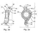
- FIG. 2 a now shows a first embodiment of a bearing device 1 according to the invention, by means of which the intermediate shaft 10 can be mounted vibration-decoupled on the engine block 100 of the vehicle.
- the bearing device 1 comprises an integrally formed bearing housing 30, which may for example consist of cast steel.
- the bearing housing 30 has a cylindrical receiving recess 36 into which the outer ring 24 of the radial bearing 20 is pressed.
- the outer ring 24 is secured in the axial direction by a securing element 26 which is designed as a spring ring, which engages in an annular groove 37 formed in the inner circumferential surface of the receiving recess 36.
- the radial bearing 20 is designed as a deep groove ball bearing, wherein the inner ring 22 of the radial bearing 20 is provided to receive the intermediate shaft 10 in itself.
- the bearing device 1 For mounting the bearing device 1 on the engine block 100 of the vehicle, the bearing device 1 now forms an interface, which consists in the embodiment shown of two first through holes 32 which are oriented orthogonal to the axis of rotation of the intermediate shaft 100. These first through-holes 32 are provided to receive in a mounting of the bearing device 1 mounting bolts 50 in itself, by means of which the bearing housing 30 of the bearing device 1 can be screwed to the engine block 100.
- damping elements 40 are now inserted into the first through-bores 32 of the bearing housing 30.
- damping elements 40 are sleeve-shaped and consist of a rubber-elastic material whose hardness is preferably in the range between 20 and 60 Shore A and which has a temperature resistance of 160 ° C or better.
- the sleeve-shaped damping elements 40 in turn form a second through-bore 42, which are aligned in the assembled state coaxially with the first through-holes 32 in the bearing housing 30.
- FIG. 2b shows again the first embodiment according to FIG. 2 a in a section along the plane AA FIG. 2a , from which the arrangement of the radial bearing 20 in the receiving recess 36 of the bearing housing 30 is clear.
- the arrangement of the retaining ring in the annular groove 37 can be clearly seen.
- FIG. 2b shows again the coaxial arrangement of the first and second through holes 32, 42 in the bearing housing 30 and in the damping elements 40, which are arranged in the first through-holes 32 of the bearing housing 30, see.
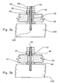
- FIG. 3 a shows again enlarged a section through one of the first through holes 32 which are formed in the bearing housing 30 of the bearing device 1.
- FIG. 3 a is the device according to the invention in contrast to the illustration of Figures 2 a and 2 b already mounted on the engine block 100.
- a sleeve-shaped damping element is inserted into the first through hole 32 of the bearing housing 30, which has the aforementioned properties.
- the longitudinal axis of the second through-bore 42 which is embodied in the sleeve-shaped damping element 40, coincides with the longitudinal axis of the first through-bore 32 in the bearing housing 30, as seen in FIG FIG. 3 a is apparent.
- a threaded bore 102 is provided into which a mounting bolt 50 is screwed, which is designed in the embodiment shown as a threaded rod.
- the threaded rod is secured in a suitable manner in the threaded bore 102 in the engine block against unintentional release.
- the threaded rod 50 is now passed through the second through hole 43 in the damping element 40.
- a washer 56 is mounted and the housing 30 is fixed by means of a nut 52 on the engine block 100. By limiting the tightening torque of the nut 30 too high compression of the damping element 40 can be safely avoided.
- the nut 52 in turn is secured against unintentional release by a screwed against the nut 52 lock nut 54th
- FIG. 3b shows an alternative embodiment of the damping element 40, which, for example, in connection with the first embodiment of the storage device 1 according to the invention according to the Figures 2 a and 2 b can be used. But it can also in connection with the second embodiment according to the FIGS. 4a to c Find use.
- FIG. 3b Instead of a sleeve-shaped damping element 40 in the region of a through-bore 32, two separately formed annular damping elements 40 are arranged, the axis of symmetry of which in turn coincides with the longitudinal axis of the first through-bore 32.
- the annular damping elements 40 each form an annular centering projection 44, which in the first through hole 32nd in the bearing housing 30 engages.
- the separately formed damping elements 40 may consist of the same material as the sleeve-shaped damping elements according to FIG. 3 a.
- FIG. 4 a shows in a simplified representation a second embodiment of a bearing device according to the invention, which differs from the first embodiment essentially in that the bearing housing 30 of the device 1 is not fixed directly to the engine block 100. Rather, a bearing housing holder 34 is provided, which is rigidly connected to the engine block 100. The bearing housing 30 is then connected in a vibration-decoupled manner to the bearing housing holder 34 in the manner already known from the first exemplary embodiment. Since the manufacturing precision of the bearing housing holder 34 is not an increased requirement, the bearing housing holder 34 may be a simple metallic casting.
- the bearing housing 30 As in the first embodiment, the outer ring 24 of the radial bearing 20 is pressed in, for which purpose the bearing housing 30 must have a correspondingly precisely machined receiving recess 36. For this reason, the bearing housing 30 may be manufactured, for example, by precision casting.
- the bearing housing 30 is mechanically fixed by means of mounting bolts 50 on the bearing housing holder 34, in which case again sleeve-shaped damping elements 40, which may correspond to those of the first embodiment, are completely connected in the power flow between the bearing housing 30 and the bearing housing holder 34.
- FIG. 4b shows the structure of the storage device 1 according to the second embodiment in detail.
- FIG. 4b can be taken, inter alia, that the bearing housing holder 34 in turn forms third through holes 38, which are provided to receive in mounting the bearing housing holder 34 on the engine block 100 more mounting bolts 50 in itself.
- damping elements 40 of the type already known, so that here results in a vibration-decoupled mounting of the bearing housing holder 34 on the engine block 100. Under certain circumstances can then be completely dispensed with a vibration-decoupled mounting of the bearing housing 30 on the bearing housing holder 34.
- Figure 4c shows again a section through the bearing device 1 according to the second embodiment, wherein the section through the plane of the paper according to the view FIG. 4b is executed.
- FIG. 5 Finally shows a third embodiment of a storage device 1 according to the invention, which substantially the first embodiment according to the FIGS. 2, 2 a and 2 b corresponds.
- the main difference is the two-part design of the bearing housing 30, wherein the bearing housing 30 comprises a fixed part 30.0, which has an interface for vibration-decoupled mounting on the engine block 100 of the motor vehicle.
- the fixed housing part 30.0 forms a first through-bore 32 into which damping elements 40 can be inserted in the manner previously known from the preceding exemplary embodiments, before the stationary housing part 30.0 is attached to the engine block 100 by means of a mounting bolt 50 which is passed through the first through-bore 32 is secured.
- the two-part bearing housing 30 also forms in this embodiment a receiving recess 36 for the outer ring 24 of the radial bearing 20, wherein due to the two-part design of the bearing housing 30 of the outer ring 24 can be determined for example by means of positive locking in the bearing housing 30.
- this two-part design of the bearing housing 30 is adapted to receive the outer ring 24 of the radial bearing 20 so that the outer ring 24 is rotatably connected to the bearing housing 30, but still a tumbling motion, in the plane of the FIG. 5 can perform. This means that the radial bearing 20 as a whole a rotational movement about the axes X and Y in FIG.
- the radial bearing 20 is fixed in the bearing housing 30, in which it is inserted into the fixed housing part 30.0 and is subsequently fixed by means of the attached flying housing part 30.1.
- the flying housing part 30.1 is fixed by means of mounting bolts 50 on the fixed housing part 30.0, to which the flying housing part 30.1 fourth through holes 39 for receiving the mounting bolts 50 is formed, and in the stationary housing part 30.0 threaded holes 33 are formed for screwing the mounting bolts 50.
Landscapes
- Engineering & Computer Science (AREA)
- General Engineering & Computer Science (AREA)
- Manufacturing & Machinery (AREA)
- Mechanical Engineering (AREA)
- Arrangement Or Mounting Of Propulsion Units For Vehicles (AREA)
- Vibration Prevention Devices (AREA)
- Support Of The Bearing (AREA)
Claims (13)
- Dispositif formant palier (1) pour supporter en rotation, d'une manière découplée en vibration, un arbre intermédiaire (10) sur le bloc-moteur (100) d'un véhicule automobile, présentant les caractéristiques suivantes:a. un palier radial (20) comprenanti. une bague intérieure (22) destinée à recevoir l'arbre intermédiaire (10), etii. une bague extérieure (24),b. un boîtier de palier (30) qui est réalisé en deux parties et dans lequel la bague extérieure (24) du palier radial (20) est immobilisée à engagement positif,i. est prévu pour1. être fixé sur le bloc-moteur (100) du véhicule automobile et2. recevoir le palier radial (20) dans son intérieur de manière solidaire en rotation, etii. forme une interface mécanique pour fixer le boîtier de palier (30) sur le bloc-moteur (100) du véhicule automobile,
dans lequelc. le dispositif formant palier (1) comprend en outre au moins un élément amortisseur (40) élastique comme le caoutchouc qui est prévu pour être disposé à amortissement de vibrations entre ledit boîtier de palier (30) et le bloc-moteur (100) lors d'un montage du boîtier de palier (30) sur le bloc-moteur (100),
caractérisé par le fait qued. le palier radial (20) immobilisé dans le boîtier de palier (30) peut exercer un mouvement chancelant autour de deux axes x, y. - Dispositif formant palier (1) selon la revendication 1, caractérisé par le fait que, lors d'un montage du boîtier de palier (30) sur le bloc-moteur (100), ledit élément amortisseur (40) est monté dans le flux de force entre le boîtier de palier (30) et le bloc-moteur (100).
- Dispositif formant palier (1) selon la revendication 2, caractérisé par le fait quea. le boîtier de palier (30) présente au moins un premier trou débouchant (32) qui est prévu pour recevoir dans son intérieur, lors d'un montage du boîtier de palier (30) sur le bloc-moteur (100), un boulon de montage (50) pour immobiliser le boîtier de palier (30) sur le bloc-moteur (100), etb. ledit élément amortisseur (40) est disposé dans ledit premier trou débouchant (32).
- Dispositif formant palier (1) selon la revendication 1, caractérisé par le fait que ledit élément amortisseur (40) présente un deuxième trou débouchant (42) destiné à recevoir le boulon de montage (50).
- Dispositif formant palier (1) selon la revendication 1, caractérisé par le fait que la bague extérieure (24) du palier radial (20) est immobilisée par liaison de force dans le boîtier de palier (30).
- Dispositif formant palier (1) selon la revendication 1, caractérisé par le fait que la bague extérieure (24) du palier radial (20) est immobilisée au moyen d'un élément de sécurité (26) dans le boîtier de palier (30).
- Dispositif formant palier (1) selon la revendication 1, caractérisé par le fait que le boîtier de palier (30) est fabriqué au moyen d'un procédé de coulée à partir d'un matériau métallique.
- Dispositif formant palier (1) selon la revendication 1, caractérisé par le fait que le dispositif (1) comprend en outre un support de boîtier de palier (34) quia. forme une première interface mécanique pour la fixation du support de boîtier de palier (34) sur le bloc-moteur (100) du véhicule automobile, etb. présente une deuxième interface mécanique pour la fixation du boîtier de palier (30) sur le support de boîtier de palier (34),
dans lequelc. ledit au moins un élément amortisseur (40) est prévu pour être disposé à amortissement de vibrations entre ledit boîtier de palier (30) et le support de boîtier de palier (34) lors d'un montage du boîtier de palier (30) sur le bloc-moteur (100). - Dispositif formant palier (1) selon la revendication 1, caractérisé par le fait que ledit au moins un élément amortisseur (40) présente une dureté qui se situe dans l'intervalle compris entre 10 et 100 Shore A, de préférence dans l'intervalle compris entre 20 et 60 Shore A.
- Dispositif formant palier (1) selon la revendication 1, caractérisé par le fait que la première fréquence propre du système apte à vibrer se composant de l'arbre intermédiaire (10), de l'arbre moteur (200), de la roue motrice (250) et du dispositif formant palier (1) est inférieure à 50 hertz, de préférence inférieure à 30 hertz.
- Dispositif formant palier (1) selon la revendication 1, caractérisé par le fait que ledit au moins un élément amortisseur (40) est résistant à une température allant jusqu'à 160 °C, de préférence jusqu'à 180 °C.
- Procédé destiné à supporter en rotation, d'une manière découplée en vibration, un arbre intermédiaire (10) sur le bloc-moteur (100) d'un véhicule automobile, comprenant les étapes de procédé suivantes:a. fournir un dispositif formant palier (1) qui comprend:i. un palier radial (20) ayant une bague intérieure (22) destinée à recevoir l'arbre intermédiaire (10), et une bague extérieure (24),ii. un boîtier de palier (30) qui1. est réalisé en deux parties et est prévu pour être fixé sur le bloc-moteur (100) du véhicule automobile, et pour recevoir à engagement positif et d'une manière solidaire en rotation ledit palier radial (20) de telle sorte que le palier radial (20) immobilisé dans le boîtier de palier (30) peut exercer un mouvement chancelant autour de deux axes x, y, et2. qui forme une interface mécanique pour fixer le boîtier de palier (30) sur le bloc-moteur (100) du véhicule automobile, etiii. au moins un élément amortisseur élastique comme le caoutchouc,b. monter le boîtier de palier (30) sur le bloc-moteur (100) du véhicule automobile, ledit au moins un élément amortisseur (40) élastique comme le caoutchouc étant disposé à amortissement de vibrations entre ledit boîtier de palier (30) et le bloc-moteur (100).
- Procédé selon la revendication 12, caractérisé par le fait que ledit au moins un élément amortisseur (40) élastique comme le caoutchouc est choisi de telle manière que la première fréquence propre du système apte à vibrer se composant de l'arbre intermédiaire (10), de l'arbre moteur (200), de la roue motrice (250) et du dispositif formant palier (1) est inférieure à 50 hertz, de préférence inférieure à 30 hertz.
Applications Claiming Priority (2)
| Application Number | Priority Date | Filing Date | Title |
|---|---|---|---|
| DE102007012958A DE102007012958A1 (de) | 2007-03-14 | 2007-03-14 | Lagervorrichtung zur schwingungsentkoppelten Drehlagerung einer Zwischenwelle am Motorblock eines Kfz und Verfahren zur schwingungsentkoppelten Drehlagerung einer Zwischenwelle am Motorblock eines Kfz |
| PCT/EP2008/052327 WO2008110455A1 (fr) | 2007-03-14 | 2008-02-26 | Dispositif de palier pour le montage en rotation découplé en oscillation d'un arbre intermédiaire sur le bloc-moteur d'un véhicule à moteur et procédé pour le montage en rotation découplé en oscillation d'un arbre intermédiaire sur le bloc-moteur d'un véh |
Publications (2)
| Publication Number | Publication Date |
|---|---|
| EP2106356A1 EP2106356A1 (fr) | 2009-10-07 |
| EP2106356B1 true EP2106356B1 (fr) | 2016-01-06 |
Family
ID=39469619
Family Applications (1)
| Application Number | Title | Priority Date | Filing Date |
|---|---|---|---|
| EP08709221.9A Active EP2106356B1 (fr) | 2007-03-14 | 2008-02-26 | Dispositif de palier pour le montage en rotation decouple en oscillation d'un arbre intermediaire sur le bloc-moteur d'un vehicule a moteur et procede pour le montage en rotation decouple en oscillation d'un arbre intermediaire sur le bloc-moteur d'un vehicule |
Country Status (4)
| Country | Link |
|---|---|
| US (1) | US8544591B2 (fr) |
| EP (1) | EP2106356B1 (fr) |
| DE (1) | DE102007012958A1 (fr) |
| WO (1) | WO2008110455A1 (fr) |
Families Citing this family (13)
| Publication number | Priority date | Publication date | Assignee | Title |
|---|---|---|---|---|
| US20140115868A1 (en) * | 2012-10-29 | 2014-05-01 | Gregory Ruhlander | Coupling System to Reduce Vibration |
| KR101439157B1 (ko) | 2013-09-26 | 2014-09-11 | 현대자동차주식회사 | 베어링브라켓의 장착구조 |
| KR101439159B1 (ko) | 2013-09-27 | 2014-09-11 | 현대자동차주식회사 | 이너 샤프트 베어링 브라켓 구조 |
| DE102013222622A1 (de) * | 2013-11-07 | 2015-05-07 | Schaeffler Technologies Gmbh & Co. Kg | Gehäuse für ein Wälzlager und Antriebsstrangabschnitt für ein Fahrzeug mit dem Gehäuse |
| KR101519753B1 (ko) * | 2013-12-18 | 2015-05-12 | 현대자동차주식회사 | 차량 파워트레인의 인너샤프트 지지 장치 |
| US10968953B2 (en) | 2015-11-25 | 2021-04-06 | Sandcraft, Llc | Greasable bearing assembly |
| US10471825B2 (en) | 2015-11-25 | 2019-11-12 | Sandcraft, Llc | Carrier bearing assembly |
| US9862269B2 (en) * | 2015-11-25 | 2018-01-09 | Jonathan D Roberts | Carrier bearing assembly |
| US9956872B2 (en) * | 2015-11-25 | 2018-05-01 | Sandcraft, Llc | Carrier bearing assembly |
| US11259972B2 (en) * | 2018-07-11 | 2022-03-01 | Richard C. Rapson, JR. | Techniques for mitigating dominant frequency imparted to object |
| US10675972B2 (en) | 2018-08-13 | 2020-06-09 | Toyota Motor Engineering & Manufacturing North America, Inc. | Drive shaft bearing support assembly and multi-radius cap for bearing support housing |
| CN114261270B (zh) * | 2021-11-02 | 2023-08-29 | 浙江零跑科技股份有限公司 | 一种汽车抗扭拉杆悬置结构 |
| DE102021130266A1 (de) | 2021-11-19 | 2023-05-25 | Schaeffler Technologies AG & Co. KG | Elektrische Maschine |
Citations (1)
| Publication number | Priority date | Publication date | Assignee | Title |
|---|---|---|---|---|
| GB2136373A (en) * | 1983-03-17 | 1984-09-19 | Riv Officine Di Villar Perosa | A transmission unit for a vehicle with a transverse engine and half-shafts of equal length |
Family Cites Families (19)
| Publication number | Priority date | Publication date | Assignee | Title |
|---|---|---|---|---|
| US2102415A (en) * | 1934-01-25 | 1937-12-14 | Chrysler Corp | Propeller shaft bearing |
| US3003831A (en) * | 1956-12-03 | 1961-10-10 | Gen Motors Corp | Bearing support |
| US3428372A (en) * | 1966-11-28 | 1969-02-18 | Chrysler Corp | Tubular housing and support |
| US3873167A (en) * | 1971-07-06 | 1975-03-25 | Trw Inc | Nonmetallic bearing housing |
| JPS5730617A (en) * | 1980-07-31 | 1982-02-18 | Toyota Motor Corp | Automobile power transmission device |
| JPS5755227A (en) * | 1980-09-16 | 1982-04-02 | Toyota Motor Corp | Power transmission for vechile |
| JPS57107626U (fr) * | 1980-12-25 | 1982-07-02 | ||
| DE3446518A1 (de) * | 1984-12-20 | 1986-07-10 | Bayerische Motoren Werke AG, 8000 München | Wellenlager |
| JPH0514010Y2 (fr) * | 1986-02-21 | 1993-04-14 | ||
| DE4317062C2 (de) * | 1993-05-21 | 1995-08-17 | Freudenberg Carl Fa | Kardanwellenlager |
| US5988341A (en) * | 1997-08-01 | 1999-11-23 | Meritor Heavy Vehicle Systems, Llc | Transmission input bearing retainer |
| US6065559A (en) * | 1998-09-22 | 2000-05-23 | Chrysler Corporation | Support structure for a vehicle powertrain |
| US6129328A (en) * | 1998-09-24 | 2000-10-10 | Cooper Tire & Rubber Company | Heat resistant engine mount |
| US6585223B1 (en) * | 1999-09-14 | 2003-07-01 | Meritor Heavy Vehicle Suspensions, Inc. | Variable compliance bushing |
| US6450474B1 (en) * | 2000-03-09 | 2002-09-17 | Lord Corporation | X-configuration engine mounting with locking end plates |
| DE10016654B4 (de) * | 2000-04-04 | 2005-10-13 | Carl Freudenberg Kg | Lagerung einer Motor-Getriebeeinheit |
| US6484976B1 (en) * | 2001-05-15 | 2002-11-26 | Gkn Automotive, Inc. | Center bearing hanger assembly |
| DE10154705B4 (de) * | 2001-11-09 | 2005-07-07 | Carl Freudenberg Kg | Lager |
| DE10212474C1 (de) * | 2002-03-20 | 2003-08-07 | Daimler Chrysler Ag | Antriebsstrang eines Kraftfahrzeuges und Verfahren zur Herstellung einer Lagereinheit |
-
2007
- 2007-03-14 DE DE102007012958A patent/DE102007012958A1/de not_active Withdrawn
-
2008
- 2008-02-26 WO PCT/EP2008/052327 patent/WO2008110455A1/fr active Application Filing
- 2008-02-26 EP EP08709221.9A patent/EP2106356B1/fr active Active
-
2009
- 2009-09-14 US US12/558,670 patent/US8544591B2/en active Active
Patent Citations (1)
| Publication number | Priority date | Publication date | Assignee | Title |
|---|---|---|---|---|
| GB2136373A (en) * | 1983-03-17 | 1984-09-19 | Riv Officine Di Villar Perosa | A transmission unit for a vehicle with a transverse engine and half-shafts of equal length |
Also Published As
| Publication number | Publication date |
|---|---|
| US20100065364A1 (en) | 2010-03-18 |
| WO2008110455A1 (fr) | 2008-09-18 |
| US8544591B2 (en) | 2013-10-01 |
| EP2106356A1 (fr) | 2009-10-07 |
| DE102007012958A1 (de) | 2008-09-25 |
Similar Documents
| Publication | Publication Date | Title |
|---|---|---|
| EP2106356B1 (fr) | Dispositif de palier pour le montage en rotation decouple en oscillation d'un arbre intermediaire sur le bloc-moteur d'un vehicule a moteur et procede pour le montage en rotation decouple en oscillation d'un arbre intermediaire sur le bloc-moteur d'un vehicule | |
| DE10258986B4 (de) | Elastisches Fahrwerklager für Nutzfahrzeuge | |
| DE102009039164A1 (de) | Lenkvorrichtung, insbesondere für eine Hinterradlenkung | |
| DE3705017A1 (de) | Antriebswellensatz fuer ein kraftfahrzeug mit quermotor | |
| EP2791533B1 (fr) | Support de frein | |
| DE102012007329A1 (de) | Welle-Nabe-Verbindung | |
| DE102016113687A1 (de) | Innenverzahntes Hohlrad für ein Spannungswellengetriebe | |
| DE102004008538B4 (de) | Differential mit einer Bolzenbefestigungsbaugruppe | |
| DE102012011601A1 (de) | Verzwängungsfreies Befestigungssystem, insbesondere zur Befestigung von Lenkgetriebegehäusen | |
| DE69801964T2 (de) | Drehmomentenanlaufschwingarm für Verbrennungsmotor | |
| WO2021197685A1 (fr) | Élément de découplage amortissant les vibrations | |
| DE19735021B4 (de) | Antriebsanordnung für ein Kraftfahrzeug | |
| DE10008606B4 (de) | Kraftübertragungsmechanismus mit einem Sprengring zu dessen Montage | |
| EP3146231B1 (fr) | Amortisseur de rotation | |
| DE102014216670B4 (de) | Lagerbuchse | |
| WO2017080794A1 (fr) | Système de roulement de roue et procédé de montage d'un système de roulement de roue | |
| DE10333495A1 (de) | Verfahren für die Herstellung einer Radaufhängung zur Reduzierung der Spurungenauigkeit | |
| WO2019166198A1 (fr) | Ensemble d'entraînement destiné un véhicule ferroviaire | |
| DE102009055107B4 (de) | Befestigungsanordnung eines Kältemittelverdichters | |
| DE102007021628A1 (de) | Antriebsaggregat für ein Fahrzeug | |
| WO2013170917A1 (fr) | Chaîne cinématique comprenant au moins un arbre de transmission à cardan | |
| DE202014103932U1 (de) | Lagerbuchse sowie schwingungsdämpfende Verbindungsanordnung | |
| DE102014216672A1 (de) | Lagerbuchse sowie schwingungsdämpfende Verbindungsanordnung | |
| DE102010050168A1 (de) | Axial gesicherte Welle-Nabe-Verbindung | |
| DE10045417A1 (de) | Lagerbock |
Legal Events
| Date | Code | Title | Description |
|---|---|---|---|
| PUAI | Public reference made under article 153(3) epc to a published international application that has entered the european phase |
Free format text: ORIGINAL CODE: 0009012 |
|
| 17P | Request for examination filed |
Effective date: 20090402 |
|
| AK | Designated contracting states |
Kind code of ref document: A1 Designated state(s): AT BE BG CH CY CZ DE DK EE ES FI FR GB GR HR HU IE IS IT LI LT LU LV MC MT NL NO PL PT RO SE SI SK TR |
|
| 17Q | First examination report despatched |
Effective date: 20090910 |
|
| DAX | Request for extension of the european patent (deleted) | ||
| RAP1 | Party data changed (applicant data changed or rights of an application transferred) |
Owner name: NEAPCO EUROPE GMBH |
|
| GRAP | Despatch of communication of intention to grant a patent |
Free format text: ORIGINAL CODE: EPIDOSNIGR1 |
|
| INTG | Intention to grant announced |
Effective date: 20150714 |
|
| GRAS | Grant fee paid |
Free format text: ORIGINAL CODE: EPIDOSNIGR3 |
|
| GRAA | (expected) grant |
Free format text: ORIGINAL CODE: 0009210 |
|
| AK | Designated contracting states |
Kind code of ref document: B1 Designated state(s): AT BE BG CH CY CZ DE DK EE ES FI FR GB GR HR HU IE IS IT LI LT LU LV MC MT NL NO PL PT RO SE SI SK TR |
|
| REG | Reference to a national code |
Ref country code: GB Ref legal event code: FG4D Free format text: NOT ENGLISH |
|
| REG | Reference to a national code |
Ref country code: CH Ref legal event code: EP |
|
| REG | Reference to a national code |
Ref country code: IE Ref legal event code: FG4D Free format text: LANGUAGE OF EP DOCUMENT: GERMAN |
|
| REG | Reference to a national code |
Ref country code: AT Ref legal event code: REF Ref document number: 768555 Country of ref document: AT Kind code of ref document: T Effective date: 20160215 |
|
| REG | Reference to a national code |
Ref country code: DE Ref legal event code: R096 Ref document number: 502008013721 Country of ref document: DE |
|
| REG | Reference to a national code |
Ref country code: FR Ref legal event code: PLFP Year of fee payment: 9 |
|
| REG | Reference to a national code |
Ref country code: LT Ref legal event code: MG4D |
|
| REG | Reference to a national code |
Ref country code: NL Ref legal event code: MP Effective date: 20160106 |
|
| PG25 | Lapsed in a contracting state [announced via postgrant information from national office to epo] |
Ref country code: BE Free format text: LAPSE BECAUSE OF NON-PAYMENT OF DUE FEES Effective date: 20160229 |
|
| PG25 | Lapsed in a contracting state [announced via postgrant information from national office to epo] |
Ref country code: NL Free format text: LAPSE BECAUSE OF FAILURE TO SUBMIT A TRANSLATION OF THE DESCRIPTION OR TO PAY THE FEE WITHIN THE PRESCRIBED TIME-LIMIT Effective date: 20160106 |
|
| PG25 | Lapsed in a contracting state [announced via postgrant information from national office to epo] |
Ref country code: ES Free format text: LAPSE BECAUSE OF FAILURE TO SUBMIT A TRANSLATION OF THE DESCRIPTION OR TO PAY THE FEE WITHIN THE PRESCRIBED TIME-LIMIT Effective date: 20160106 Ref country code: IT Free format text: LAPSE BECAUSE OF FAILURE TO SUBMIT A TRANSLATION OF THE DESCRIPTION OR TO PAY THE FEE WITHIN THE PRESCRIBED TIME-LIMIT Effective date: 20160106 Ref country code: NO Free format text: LAPSE BECAUSE OF FAILURE TO SUBMIT A TRANSLATION OF THE DESCRIPTION OR TO PAY THE FEE WITHIN THE PRESCRIBED TIME-LIMIT Effective date: 20160406 Ref country code: GR Free format text: LAPSE BECAUSE OF FAILURE TO SUBMIT A TRANSLATION OF THE DESCRIPTION OR TO PAY THE FEE WITHIN THE PRESCRIBED TIME-LIMIT Effective date: 20160407 Ref country code: FI Free format text: LAPSE BECAUSE OF FAILURE TO SUBMIT A TRANSLATION OF THE DESCRIPTION OR TO PAY THE FEE WITHIN THE PRESCRIBED TIME-LIMIT Effective date: 20160106 Ref country code: HR Free format text: LAPSE BECAUSE OF FAILURE TO SUBMIT A TRANSLATION OF THE DESCRIPTION OR TO PAY THE FEE WITHIN THE PRESCRIBED TIME-LIMIT Effective date: 20160106 |
|
| REG | Reference to a national code |
Ref country code: DE Ref legal event code: R082 Ref document number: 502008013721 Country of ref document: DE Representative=s name: LOHMANNS, BERNARD, DIPL.-PHYS., DE |
|
| PG25 | Lapsed in a contracting state [announced via postgrant information from national office to epo] |
Ref country code: LV Free format text: LAPSE BECAUSE OF FAILURE TO SUBMIT A TRANSLATION OF THE DESCRIPTION OR TO PAY THE FEE WITHIN THE PRESCRIBED TIME-LIMIT Effective date: 20160106 Ref country code: IS Free format text: LAPSE BECAUSE OF FAILURE TO SUBMIT A TRANSLATION OF THE DESCRIPTION OR TO PAY THE FEE WITHIN THE PRESCRIBED TIME-LIMIT Effective date: 20160506 Ref country code: PL Free format text: LAPSE BECAUSE OF FAILURE TO SUBMIT A TRANSLATION OF THE DESCRIPTION OR TO PAY THE FEE WITHIN THE PRESCRIBED TIME-LIMIT Effective date: 20160106 Ref country code: SE Free format text: LAPSE BECAUSE OF FAILURE TO SUBMIT A TRANSLATION OF THE DESCRIPTION OR TO PAY THE FEE WITHIN THE PRESCRIBED TIME-LIMIT Effective date: 20160106 Ref country code: PT Free format text: LAPSE BECAUSE OF FAILURE TO SUBMIT A TRANSLATION OF THE DESCRIPTION OR TO PAY THE FEE WITHIN THE PRESCRIBED TIME-LIMIT Effective date: 20160506 Ref country code: LT Free format text: LAPSE BECAUSE OF FAILURE TO SUBMIT A TRANSLATION OF THE DESCRIPTION OR TO PAY THE FEE WITHIN THE PRESCRIBED TIME-LIMIT Effective date: 20160106 |
|
| REG | Reference to a national code |
Ref country code: CH Ref legal event code: PL |
|
| REG | Reference to a national code |
Ref country code: DE Ref legal event code: R097 Ref document number: 502008013721 Country of ref document: DE |
|
| PG25 | Lapsed in a contracting state [announced via postgrant information from national office to epo] |
Ref country code: DK Free format text: LAPSE BECAUSE OF FAILURE TO SUBMIT A TRANSLATION OF THE DESCRIPTION OR TO PAY THE FEE WITHIN THE PRESCRIBED TIME-LIMIT Effective date: 20160106 Ref country code: MC Free format text: LAPSE BECAUSE OF FAILURE TO SUBMIT A TRANSLATION OF THE DESCRIPTION OR TO PAY THE FEE WITHIN THE PRESCRIBED TIME-LIMIT Effective date: 20160106 Ref country code: LI Free format text: LAPSE BECAUSE OF NON-PAYMENT OF DUE FEES Effective date: 20160229 Ref country code: CH Free format text: LAPSE BECAUSE OF NON-PAYMENT OF DUE FEES Effective date: 20160229 Ref country code: EE Free format text: LAPSE BECAUSE OF FAILURE TO SUBMIT A TRANSLATION OF THE DESCRIPTION OR TO PAY THE FEE WITHIN THE PRESCRIBED TIME-LIMIT Effective date: 20160106 |
|
| PLBE | No opposition filed within time limit |
Free format text: ORIGINAL CODE: 0009261 |
|
| STAA | Information on the status of an ep patent application or granted ep patent |
Free format text: STATUS: NO OPPOSITION FILED WITHIN TIME LIMIT |
|
| PG25 | Lapsed in a contracting state [announced via postgrant information from national office to epo] |
Ref country code: CZ Free format text: LAPSE BECAUSE OF FAILURE TO SUBMIT A TRANSLATION OF THE DESCRIPTION OR TO PAY THE FEE WITHIN THE PRESCRIBED TIME-LIMIT Effective date: 20160106 Ref country code: SK Free format text: LAPSE BECAUSE OF FAILURE TO SUBMIT A TRANSLATION OF THE DESCRIPTION OR TO PAY THE FEE WITHIN THE PRESCRIBED TIME-LIMIT Effective date: 20160106 Ref country code: RO Free format text: LAPSE BECAUSE OF FAILURE TO SUBMIT A TRANSLATION OF THE DESCRIPTION OR TO PAY THE FEE WITHIN THE PRESCRIBED TIME-LIMIT Effective date: 20160106 |
|
| REG | Reference to a national code |
Ref country code: IE Ref legal event code: MM4A |
|
| 26N | No opposition filed |
Effective date: 20161007 |
|
| PG25 | Lapsed in a contracting state [announced via postgrant information from national office to epo] |
Ref country code: IE Free format text: LAPSE BECAUSE OF NON-PAYMENT OF DUE FEES Effective date: 20160226 |
|
| REG | Reference to a national code |
Ref country code: FR Ref legal event code: PLFP Year of fee payment: 10 |
|
| PG25 | Lapsed in a contracting state [announced via postgrant information from national office to epo] |
Ref country code: BG Free format text: LAPSE BECAUSE OF FAILURE TO SUBMIT A TRANSLATION OF THE DESCRIPTION OR TO PAY THE FEE WITHIN THE PRESCRIBED TIME-LIMIT Effective date: 20160406 Ref country code: SI Free format text: LAPSE BECAUSE OF FAILURE TO SUBMIT A TRANSLATION OF THE DESCRIPTION OR TO PAY THE FEE WITHIN THE PRESCRIBED TIME-LIMIT Effective date: 20160106 |
|
| REG | Reference to a national code |
Ref country code: AT Ref legal event code: MM01 Ref document number: 768555 Country of ref document: AT Kind code of ref document: T Effective date: 20160226 |
|
| PG25 | Lapsed in a contracting state [announced via postgrant information from national office to epo] |
Ref country code: AT Free format text: LAPSE BECAUSE OF NON-PAYMENT OF DUE FEES Effective date: 20160226 |
|
| PG25 | Lapsed in a contracting state [announced via postgrant information from national office to epo] |
Ref country code: MT Free format text: LAPSE BECAUSE OF FAILURE TO SUBMIT A TRANSLATION OF THE DESCRIPTION OR TO PAY THE FEE WITHIN THE PRESCRIBED TIME-LIMIT Effective date: 20160106 |
|
| REG | Reference to a national code |
Ref country code: FR Ref legal event code: PLFP Year of fee payment: 11 |
|
| PG25 | Lapsed in a contracting state [announced via postgrant information from national office to epo] |
Ref country code: CY Free format text: LAPSE BECAUSE OF FAILURE TO SUBMIT A TRANSLATION OF THE DESCRIPTION OR TO PAY THE FEE WITHIN THE PRESCRIBED TIME-LIMIT Effective date: 20160106 Ref country code: HU Free format text: LAPSE BECAUSE OF FAILURE TO SUBMIT A TRANSLATION OF THE DESCRIPTION OR TO PAY THE FEE WITHIN THE PRESCRIBED TIME-LIMIT; INVALID AB INITIO Effective date: 20080226 |
|
| PG25 | Lapsed in a contracting state [announced via postgrant information from national office to epo] |
Ref country code: LU Free format text: LAPSE BECAUSE OF NON-PAYMENT OF DUE FEES Effective date: 20160226 Ref country code: TR Free format text: LAPSE BECAUSE OF FAILURE TO SUBMIT A TRANSLATION OF THE DESCRIPTION OR TO PAY THE FEE WITHIN THE PRESCRIBED TIME-LIMIT Effective date: 20160106 |
|
| PGFP | Annual fee paid to national office [announced via postgrant information from national office to epo] |
Ref country code: DE Payment date: 20240216 Year of fee payment: 17 Ref country code: GB Payment date: 20240222 Year of fee payment: 17 |
|
| PGFP | Annual fee paid to national office [announced via postgrant information from national office to epo] |
Ref country code: FR Payment date: 20240222 Year of fee payment: 17 |