EP2105544A1 - Brandschutzelement für eine Sanitäreinrichtung, Sanitäreinrichtung mit einem solchen Brandschutzelement und Brandverschluss-Set für eine Sanitäreinrichtung - Google Patents
Brandschutzelement für eine Sanitäreinrichtung, Sanitäreinrichtung mit einem solchen Brandschutzelement und Brandverschluss-Set für eine Sanitäreinrichtung Download PDFInfo
- Publication number
- EP2105544A1 EP2105544A1 EP08405091A EP08405091A EP2105544A1 EP 2105544 A1 EP2105544 A1 EP 2105544A1 EP 08405091 A EP08405091 A EP 08405091A EP 08405091 A EP08405091 A EP 08405091A EP 2105544 A1 EP2105544 A1 EP 2105544A1
- Authority
- EP
- European Patent Office
- Prior art keywords
- fire protection
- protection element
- fire
- mounting frame
- opening
- Prior art date
- Legal status (The legal status is an assumption and is not a legal conclusion. Google has not performed a legal analysis and makes no representation as to the accuracy of the status listed.)
- Granted
Links
Images


Classifications
-
- E—FIXED CONSTRUCTIONS
- E03—WATER SUPPLY; SEWERAGE
- E03D—WATER-CLOSETS OR URINALS WITH FLUSHING DEVICES; FLUSHING VALVES THEREFOR
- E03D11/00—Other component parts of water-closets, e.g. noise-reducing means in the flushing system, flushing pipes mounted in the bowl, seals for the bowl outlet, devices preventing overflow of the bowl contents; devices forming a water seal in the bowl after flushing, devices eliminating obstructions in the bowl outlet or preventing backflow of water and excrements from the waterpipe
- E03D11/13—Parts or details of bowls; Special adaptations of pipe joints or couplings for use with bowls, e.g. provisions in bowl construction preventing backflow of waste-water from the bowl in the flushing pipe or cistern, provisions for a secondary flushing, for noise-reducing
- E03D11/14—Means for connecting the bowl to the wall, e.g. to a wall outlet
- E03D11/143—Mounting frames for toilets and urinals
- E03D11/146—Mounting frames for toilets and urinals with incorporated cistern
-
- F—MECHANICAL ENGINEERING; LIGHTING; HEATING; WEAPONS; BLASTING
- F16—ENGINEERING ELEMENTS AND UNITS; GENERAL MEASURES FOR PRODUCING AND MAINTAINING EFFECTIVE FUNCTIONING OF MACHINES OR INSTALLATIONS; THERMAL INSULATION IN GENERAL
- F16L—PIPES; JOINTS OR FITTINGS FOR PIPES; SUPPORTS FOR PIPES, CABLES OR PROTECTIVE TUBING; MEANS FOR THERMAL INSULATION IN GENERAL
- F16L5/00—Devices for use where pipes, cables or protective tubing pass through walls or partitions
- F16L5/02—Sealing
- F16L5/04—Sealing to form a firebreak device
Definitions
- the invention relates to a fire protection element for a sanitary device having a mounting frame for a sanitary body and arranged in front of the mounting frame wall with at least one opening to be closed with the fire protection element, wherein the fire protection element has a housing in which a fire protection is arranged, in case of fire expanded.
- Sanitary facilities usually have breakthroughs through which fire and smoke can pass in case of fire, if no fire protection measures are taken.
- Fire protection elements serve to close these openings in case of fire. They have, for example, intumescent material which expands at a predetermined temperature by a multiple of its volume and thus closes all passages.
- the openings to be closed for example, openings in a cover, which is made for example of plasterboard.
- the openings are for example the inspection opening for a cistern, which is arranged behind the wall or passages for a flushing pipe and a drain pipe of a ceramic body, for example a toilet bowl.
- connection device for sanitary body in which in an opening of a planking a sleeve is inserted, within which a fire protection material is arranged. In case of fire, the fire protection material closes the passage through the planking as a result of its expansion.
- closure lid By the DE-A-196 47 241 is a closure lid has become known, which is used in an inspection opening for fire walls and ceilings.
- the closure lid has a frame in which a front plate is inserted. Next strips of intumescent material are provided. A hinge allows you to unfold.
- the DE-A-198 34 941 discloses a fire barrier for pipe penetrations through a mounting wall made of plasterboard.
- a metal plate forms a housing in which expanding fire protection material is used.
- the plate has a passage and at least one tubular extension which is lined on the inside with the fire protection material.
- the invention has for its object to provide a fire protection element of the type mentioned that is very easy to install in sanitary facilities as a standard element in the shell.
- the fire protection element should still be inexpensive to produce and allow effective fire protection.
- the invention is achieved according to claim 1, characterized in that it has fastening means for its attachment to the mounting frame.
- the fire protection element can thus be fixed in the shell on the mounting frame, if fire protection is desired.
- the fire protection element is connected in case of fire with the mounting frame and also remains in the intended position when other parts are destroyed and, for example, melted away. In particular, a locking connection is provided, which can be easily and without tools added and released again.
- the fire protection element is provided for example for the closure of the inspection opening for a cistern.
- it preferably forms the closure plate, which is usually arranged in such an inspection opening and has openings for a presser bar and fastening elements, for example threaded bolts. In a revision of this fire protection element or a part of this element can be removed from the inspection opening, so that the cistern is accessible for a revision.
- the Fire protection element preferably has a plate which is attachable to the mounting frame.
- the fastening means for securing the fire protection element are according to an embodiment of the invention sheet metal parts. These are also preserved in case of fire and can be made very easily and cheaply.
- the sheet metal parts also allow easy attachment, for example, with a locking part and a suspension part. During assembly, the fire protection element can be hung on the mounting frame and locked with a pivoting movement on the mounting frame.
- the fire protection material is plate-shaped and sandwiched between two metal plates.
- the sheet metal plates form a housing against which the fire protection material can expand.
- the plates or the housing form a back pressure, so that the fire protection material expands into openings or openings and closes them therewith.
- At least one of the two sheet metal plates has an opening through which in the event of fire expanding fire protection material can escape and that this at least one opening is closed by a wegschmelzendes part in case of fire. If all passages and openings are closed, a very high pressure would build up as the fire protection material continues to expand. This can be avoided by the fire protection material can escape after the melting away of said part through the opening.
- the fire protection element for thermal insulation has at least one metal plate having a fire-resistant paint.
- a plate of calcium silicate or a similar material is provided. The fire protection element prevents in this case not only the passage of fire and smoke, but also the passage of heat through the openings to be closed.
- the invention also relates to a sanitary device with a mounting frame, arranged in front of this and at least one opening having wall, for example, plasterboard and at least one fire protection element.
- the sanitary device is for example a toilet facility with a cistern and a toilet bowl.
- the sanitary device may also have, for example, a urinal or, for example, a washing basin.
- a sanitary device has two fire protection elements, wherein one is provided for the inspection opening of the cistern and the other for the connection of the ceramic body. Both fire protection elements can be installed in the shell and thus before mounting the wall and the ceramic body. With suitable building protection elements, these can be protected during further expansion. These building protection elements are then finally removed.
- the fire protection elements are thus components with which the sanitary device can be equipped in the event of a desired fire protection. If such fire protection is not required, then these fire protection elements are not mounted accordingly.
- the usual parts and elements of the sanitary device are the same.
- the novel fire protection elements are thus also advantageous in terms of storage.
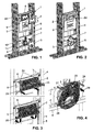
- the sanitary device 1 has a mounting frame 4, according to FIG. 5 placed on a building floor 23 and supported on a building wall, not shown here. It can according to the Figures 1 and 2 Be supplemented by Beplankungsschienen 55, where a wall 12 is mounted from plates 13. On a front side 16 of the wall 12, for example tiles not shown here can be attached.
- the mounting frame 4 has two vertical struts 5 and trusses 6, 7 and 8, which are fixedly connected to these vertical struts 5.
- a cistern 9 is mounted, which has an actuator 19 for a drain valve 18 in the usual manner.
- the operation of the Drain valve 18 is carried out on a button 21 which is mounted in an actuating plate 20 and which is connected via a presser bar 56 with the actuating device 19.
- the pusher rod 56 extends through an opening 14 of the wall 12, which is covered with the actuator plate 20.
- the cistern 9 has a corresponding opening 57.
- a fire protection element 2 is used, which is releasably secured to the mounting frame 4 and which can be removed in a revision of the cistern 9 after removing the actuator plate 20, so that the opening 57 of Cistern 9 is free.
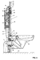
- the cistern 9 is according to a flush pipe 10 FIG. 5 connected to a toilet bowl 22 or other ceramic part, such as a urinal bowl.
- the flushing pipe 10 is connected through a further opening 15 of the wall 12 through to the toilet bowl 22.
- the toilet bowl 22 is connected via a sleeve 58 with a drain pipe 11.
- the sleeve 58 passes through the opening 15 and connects in a known manner the toilet bowl 22 with the drain pipe 11.
- a further fire protection element 3 is inserted and engages around the sleeve 58 and a tube 59, which the flushing pipe 10 with the toilet bowl 22 connects.
- the fire protection element 3 is also releasably secured to the mounting frame 4.
- the fire protection element 2 has according FIG. 8 a plate 42 having an opening 44 which is surrounded by a collar 43 on which a frame 41 is placed.
- the plate 42 is made of sheet metal and the frame 41 made of a fire protection material, in particular intumescent material.
- an insert 61 is inserted, which consists of a housing 31 made of two plates 37 made of sheet metal and three plates 36 made of fire protection material.
- the plates 37 and the plates 36 are held together by screws 39 which are inserted through holes 60 therethrough. Between the two plates 37 39 sleeves 38 are arranged on the screws, which project into the holes 60 of the plates 37 inside. With screws 40, the insert 61 is releasably secured to the plate 42.
- the insert 61 can thus be removed from the plate 42 by loosening the fastening screws 40.
- the plates 36 and 37 have openings 63 for the passage of the presser rods 56 and an opening 62 for the passage of operating parts, not shown here. Expand in case of fire above a predetermined temperature, the frame 41 and the plates 36. Here, the opening 14 is completely closed, so that fire and smoke can not penetrate through them. Also, the openings 62 and 63 are closed by the expansion of the plates 36. Upon exposure to heat, the sleeves 38 made of plastic melt so that the fire protection material can continue to expand. An excessive and dangerous pressure between the plates 37 can be avoided.
- the insert 61 is sandwiched, as shown, from the plates 36 and 37. Instead of three plates 36, fewer or more such plates 36 may be provided. In principle, an embodiment with only one plate 36 is possible.
- the plates 36 can also be made of several individual parts.
- each other two fasteners 24 are arranged, which are bent sheet metal parts and which serve as a fastening tab. Laterally below two other mounting hardware 25 are arranged opposite, which are also bent sheet metal parts. These parts 25 are latching elements and each have a laterally projecting latching tongue 25a.
- the fire protection element 2 can be attached very easily and quickly without tools on the mounting frame 4, as the FIG. 3 shows.
- the fire protection element 2 is applied with the fastening parts 24 on the cross member 6, as in FIG. 3 shown above. Subsequently, the fire protection element 2 is pivoted downward, so that the fastening parts 25 each engage on a vertical strut 5.
- the fire protection element 2 is thus safe in the shell before attaching the wall 12 in the intended position, yet easily releasably positioned.
- a building protection element 64 is placed on the fire protection element 2 for further expansion, which is then removed later.
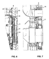
- fire protection element 3 is used as mentioned above in the corresponding opening 15. It has an upper passage 45 for the flush pipe 10 and a lower major passage 46 for the drain pipe 11. It has according to the Figures 10 and 13 a back 17, a thermal insulation board 47, which is made for example of calcium silicate.
- This heat insulation plate 47 is provided with a Metal plate 48 connected, for example screwed, which has an edge 49 which is made of bent sheet metal parts.
- a frame 51 made of intumescent material and thus made of fire protection material. The frame 51 thus completely surrounds the edge 49.
- a plate 50 is disposed on the metal plate 48, which is also made of fire protection material.
- a U-shaped holder 53 made of sheet metal is fixed in an upper region, are inserted into the strip 35 of fire protection material.
- Another arcuate holder 52 is fixed in a lower region on the edge 49. This takes up annularly arranged strip 35. The strips 35 thus form a fire protection material 32 and the strips 35 another fire protection material 33.
- a front plate 54 is fixed to the frame 49 made of sheet metal, for example screwed. The two plates 48 and 54 thus form a housing in which the fire protection material 32 and the fire protection material 33 are arranged. In case of fire, the fire protection material 32 and the fire protection material 33 expands and fills the passages 45 and 46, wherein the holders 52 and 53 absorb the back pressure.
- the sleeve 58 and the tube 59 are completely compressed.
- the corresponding passages 45 and 46 are thus closed by the fire protection material 32 and 33, respectively. Fire and smoke can not pass through the wall 12 thus.
- the plate 47 prevents heat from spreading through the opening 15. The fire protection works in both directions and thus in FIG. 5 from the front 16 to the back 17 as well as in the other direction.
- fasteners 26 and 27 are fixed, in particular screwed. These parts 26 and 27 are preferably also made of sheet metal. They allow attachment of the fire protection element 3 on the mounting frame 4, as in FIG. 4 is shown. With the two fastening parts 26, the fire protection element 3 is placed on the traverse 8. In the direction of the arrows 29, the fire protection element 3 is now tilted, so that the fastening parts 27 engage resiliently on the upper traverse 7. The fire protection element 3 can thus be attached to the mounting frame 4 very easily and without tools.
- the two passages 45 and 46 can be closed in a conventional manner with a building protection, as in FIG. 2 is shown.
Landscapes
- Engineering & Computer Science (AREA)
- General Engineering & Computer Science (AREA)
- Health & Medical Sciences (AREA)
- Life Sciences & Earth Sciences (AREA)
- Hydrology & Water Resources (AREA)
- Public Health (AREA)
- Water Supply & Treatment (AREA)
- Mechanical Engineering (AREA)
- Sanitary Device For Flush Toilet (AREA)
Abstract
Description
- Die Erfindung betrifft ein Brandschutzelement für eine Sanitäreinrichtung, die ein Montagegestell für einen Sanitärkörper und eine vor dem Montagegestell angeordnete Wand mit wenigstens einer mit dem Brandschutzelement zu verschliessende Öffnung aufweist, wobei das Brandschutzelement ein Gehäuse aufweist, in dem ein Brandschutzmittel angeordnet ist, das im Brandfall expandiert. Sanitäreinrichtungen besitzen in der Regel Durchbrüche, durch die im Brandfall Feuer und Rauch hindurchtreten kann, wenn keine Brandschutzmassnahmen getroffen sind. Brandschutzelemente dienen dazu, diese Öffnungen im Brandfall zu verschliessen. Sie weisen beispielsweise intumeszierendes Material auf, das sich bei einer vorbestimmten Temperatur um ein Mehrfaches seines Volumens ausdehnt und damit sämtliche Durchgänge verschliesst. Die Öffnungen, die verschlossen werden sollen, sind beispielsweise Öffnungen in einer Abdeckwand, die beispielsweise aus Gipskartonplatten hergestellt ist. Die Öffnungen sind beispielsweise die Revisionsöffnung für einen Spülkasten, welcher hinter der Wand angeordnet ist oder Durchgänge für ein Spülrohr und ein Abflussrohr eines Keramikkörpers, beispielsweise einer WC-Schüssel.
- Im Stand der Technik ist durch die
EP-A-1 550 775 des Anmelders eine Anschlussvorrichtung für Sanitärkörper bekannt geworden, bei welcher in einer Öffnung einer Beplankung eine Muffe eingesetzt ist, innerhalb der ein Brandschutzmaterial angeordnet ist. Im Brandfall verschliesst das Brandschutzmaterial infolge seiner Expansion den Durchgang durch die Beplankung. - Durch die
DE-A-196 47 241 ist ein Verschlussdeckel bekannt geworden, der in eine Revisionsöffnung für Brandschutzwände und -decken einsetzbar ist. Der Verschlussdeckel besitzt einen Rahmen, in den eine vordere Platte eingesetzt ist. Weiter sind Streifen aus aufschäumendem Material vorgesehen. Ein Scharnier ermöglicht ein Aufklappen. - Die
DE-A-198 34 941 offenbart ein Brandschutzschott für Rohrdurchführungen durch eine Montagewand aus Gipskartonplatten. Bei diesem bildet eine Blechplatte ein Gehäuse, in dem expandierendes Brandschutzmaterial eingesetzt ist. Die Platte besitzt einen Durchgang sowie wenigstens einen rohrförmigen Ansatz, der innenseitig mit dem Brandschutzmaterial ausgekleidet ist. - Der Erfindung liegt die Aufgabe zugrunde, ein Brandschutzelement der genannten Art zu schaffen, das bei Sanitäreinrichtungen wahlweise als Standardelement sehr einfach im Rohbau montierbar ist. Das Brandschutzelement soll trotzdem kostengünstig herstellbar und einen wirksamen Brandschutz ermöglichen.
- Die Erfindung ist gemäss Anspruch 1 dadurch gelöst, dass es Befestigungsmittel zu seiner Befestigung am Montagegestell aufweist. Das Brandschutzelement kann somit im Rohbau am Montagegestell befestigt werden, falls ein Brandschutz gewünscht ist. Das Brandschutzelement ist im Brandfall mit dem Montagegestell verbunden und verbleibt auch dann in der vorgesehenen Position, wenn andere Teile zerstört und beispielsweise weggeschmolzen sind. Insbesondere ist eine Rastverbindung vorgesehen, die einfach und ohne Werkzeuge gefügt und wieder gelöst werden kann. Das Brandschutzelement ist beispielsweise für den Verschluss der Revisionsöffnung für einen Spülkasten vorgesehen. Es bildet in diesem Fall vorzugsweise die Verschlussplatte, die üblicherweise in einer solchen Revisionsöffnung angeordnet ist und Durchbrüche für eine Drückerstange und Befestigungselemente, beispielsweise Gewindebolzen aufweist. Bei einer Revision kann dieses Brandschutzelement oder ein Teil dieses Elements aus der Revisionsöffnung herausgenommen werden, so dass der Spülkasten für eine Revision zugänglich ist. Das Brandschutzelement besitzt vorzugsweise eine Platte, die am Montagegestell befestigbar ist.
- Die Befestigungsmittel zum Befestigen des Brandschutzelements sind gemäss einer Weiterbildung der Erfindung Blechteile. Diese bleiben auch im Brandfall erhalten und können sehr einfach und günstig hergestellt werden. Die Blechteile ermöglichen auch eine einfache Befestigung, beispielsweise mit einem Rastteil und einem Einhängeteil. Bei der Montage kann das Brandschutzelement am Montagegestell eingehängt und mit einer Schwenkbewegung am Montagerahmen verrastet werden.
- Nach einer Weiterbildung der Erfindung ist vorgesehen, dass das Brandschutzmaterial plattenförmig ausgebildet und sandwichartig zwischen zwei Blechplatten angeordnet ist. Die Blechplatten bilden ein Gehäuse, gegen das das Brandschutzmaterial sich expandieren kann. Die Platten bzw. das Gehäuse bilden einen Gegendruck, so dass das Brandschutzmaterial in Öffnungen bzw. Durchbrüche expandiert und diese damit verschliesst.
- Nach einer Weiterbildung der Erfindung ist vorgesehen, dass wenigstens eine der beiden Blechplatten eine Öffnung aufweist, durch welche im Brandfall expandierendes Brandschutzmaterial austreten kann und dass diese wenigstens eine Öffnung durch ein im Brandfall wegschmelzendes Teil verschlossen ist. Sind sämtliche Durchgänge und Öffnungen verschlossen, so würde sich bei weiter expandierendem Brandschutzmaterial ein sehr hoher Druck aufbauen. Dieser kann vermieden werden, indem das Brandschutzmaterial nach dem Wegschmelzen des genannten Teils durch die Öffnung austreten kann.
- Nach einer Weiterbildung der Erfindung ist vorgesehen, dass das Brandschutzelement zur Wärmedämmung wenigstens eine Metallplatte aufweist, die einen Brandschutz-Farbanstrich aufweist. Alternativ ist eine Platte aus Kalziumsilikat oder einem ähnlichen Material vorgesehen. Das Brandschutzelement verhindert in diesem Fall nicht nur den Durchgang von Feuer und Rauch, sondern auch den Durchgang von Hitze durch die zu verschliessenden Öffnungen.
- Die Erfindung betrifft auch eine Sanitäreinrichtung mit einem Montagegestell, einer vor diesem angeordneten und wenigstens eine Öffnung aufweisenden Wand, beispielsweise aus Gipskarton und wenigstens einem Brandschutzelement. Die Sanitäreinrichtung ist beispielsweise eine WC-Einrichtung mit einem Spülkasten und einer WC-Schüssel. Die Sanitäreinrichtung kann aber auch beispielsweise ein Urinal oder beispielsweise eine Waschschüssel aufweisen. Vorzugsweise besitzt eine solche Sanitäreinrichtung zwei Brandschutzelemente, wobei das eine für die Revisionsöffnung des Spülkastens und das andere für den Anschluss des Keramikkörpers vorgesehen ist. Beide Brandschutzelemente können im Rohbau und somit vor der Montage der Wand und des Keramikkörpers montiert werden. Mit geeigneten Bauschutzelementen können diese beim weiteren Ausbau geschützt werden. Dies Bauschutzelemente werden dann schlussendlich entfernt.
- Bei einer solchen Sanitäreinrichtung sind die Brandschutzelemente somit Bauteile, mit denen die Sanitäreinrichtung im Fall eines gewünschten Brandschutzes ausgerüstet werden kann. Ist ein solcher Brandschutz nicht erforderlich, so werden entsprechend diese Brandschutzelemente nicht montiert. Ausser den Brandschutzelementen sind die üblichen Teile und Elemente der Sanitäreinrichtung gleich. Die erfindungsgemässen Brandschutzelemente sind somit auch im Hinblick auf die Lagerhaltung vorteilhaft.
- Weitere vorteilhafte Merkmale ergeben sich aus den abhängigen Patentansprüchen, der nachfolgenden Beschreibung sowie der Zeichnung.
- Ein Ausführungsbeispiel der Erfindung wird nachfolgend anhand der Zeichnung näher erläutert. Es zeigen:
- Figur 1
- schematisch eine Sanitäreinrichtung im Rohbau sowie zwei Brandschutzelemente vor der Montage,
- Figur 2
- eine Sanitäreinrichtung gemäss
Figur 1 , jedoch mit montierten Brandschutzelementen, - Figur 3
- schematisch das Befestigen eines Brandschutzelementes an einem Montagegestell,
- Figur 4
- schematisch das Montieren eines Brandschutzelementes am Montagegestell,
- Figur 5
- ein vertikaler Schnitt durch eine fertig erstellte Sanitäreinrichtung,
- Figur 6
- ein vergrösserter Ausschnitt aus der
Figur 5 im Bereich der Revisionsöffnung des Spülkastens, - Figur 7
- ein vergrösserter Ausschnitt aus der
Figur 4 im Bereich des Anschlusses des Keramikkörpers, - Figur 8
- eine räumliche Ansicht eines erfindungsgemässen Brandschutzelementes, wobei einzelne Teile aus zeichnerischen Gründen auseinander gezogen sind,
- Figur 9
- eine Ansicht eines erfindungsgemässen Brandschutzelementes,
- Figur 10
- ein Schnitt durch das Brandschutzelement entlang der Linie X-X der
Figur 9 , - Fig. 11 + 12
- räumliche Ansichten des Brandschutzelementes gemäss den
Figuren 9 bis 10 und - Figur 13
- eine räumliche Ansicht des Brandschutzelementes gemäss den
Figuren 9 bis 12 , wobei einzelne Teile aus zeichnerischen Gründen auseinander gezogen sind. - Die Sanitäreinrichtung 1 weist ein Montagegestell 4 auf, das gemäss
Figur 5 auf einen Gebäudeboden 23 gestellt und an einer hier nicht gezeigten Gebäudewand abgestützt ist. Es kann gemäss denFiguren 1 und 2 durch Beplankungsschienen 55 ergänzt sein, an denen eine Wand 12 aus Platten 13 gelagert ist. An einer Vorderseite 16 der Wand 12 können beispielsweise hier nicht gezeigte Fliesen angebracht werden. Das Montagegestell 4 besitzt zwei Vertikalstreben 5 und Traversen 6, 7 und 8, die mit diesen Vertikalstreben 5 fest verbunden sind. Im Montagegestell 4 ist ein Spülkasten 9 gelagert, der in üblicher Weise eine Betätigungsvorrichtung 19 für ein Ablaufventil 18 aufweist. Die Betätigung des Ablaufventils 18 erfolgt an einer Taste 21, die in einer Betätigungsplatte 20 gelagert ist und die über eine Drückerstange 56 mit der Betätigungsvorrichtung 19 verbunden ist. Die Drückerstange 56 durchragt eine Öffnung 14 der Wand 12, welche mit der Betätigungsplatte 20 abgedeckt ist. Der Spülkasten 9 besitzt eine entsprechende Öffnung 57. In die Öffnung 14 ist ein Brandschutzelement 2 eingesetzt, das am Montagegestell 4 lösbar befestigt ist und das bei einer Revision des Spülkastens 9 nach dem Entfernen der Betätigungsplatte 20 abgenommen werden kann, so dass die Öffnung 57 des Spülkastens 9 frei ist. - Der Spülkasten 9 ist über ein Spülrohr 10 gemäss
Figur 5 mit einer WC-Schüssel 22 oder einem anderen Keramikteil, beispielsweise einer Urinalschüssel verbunden. Das Spülrohr 10 ist durch eine weitere Öffnung 15 der Wand 12 hindurch mit der WC-Schüssel 22 verbunden. Die WC-Schüssel 22 ist über eine Muffe 58 mit einem Abflussrohr 11 verbunden. Die Muffe 58 geht durch die Öffnung 15 hindurch und verbindet in bekannter Weise die WC-Schüssel 22 mit dem Abflussrohr 11. In die Öffnung 15 ist ein weiteres Brandschutzelement 3 eingesetzt und umgreift die Muffe 58 als auch ein Rohr 59, welches das Spülrohr 10 mit der WC-Schüssel 22 verbindet. Das Brandschutzelement 3 ist ebenfalls am Montagegestell 4 lösbar befestigt. - Das Brandschutzelement 2 besitzt gemäss
Figur 8 eine Platte 42, die eine Öffnung 44 besitzt, die von einem Kragen 43 umgeben ist, auf den ein Rahmen 41 aufgesetzt ist. Die Platte 42 besteht aus Blech und der Rahmen 41 aus einem Brandschutzmaterial, insbesondere intumeszierendem Material. In die Öffnung 44 ist ein Einsatz 61 eingesetzt, der ein Gehäuse 31 aus zwei aus Blech hergestellten Platten 37 und drei Platten 36 aus Brandschutzmaterial besteht. Die Platten 37 und die Platten 36 sind mit Schrauben 39 zusammengehalten, welche durch Bohrungen 60 hindurch gesteckt sind. Zwischen den beiden Platten 37 sind auf den Schrauben 39 Hülsen 38 angeordnet, welche in die Bohrungen 60 der Platten 37 hinein ragen. Mit Schrauben 40 ist der Einsatz 61 an der Platte 42 lösbar befestigt. Bei einer Revision kann somit der Einsatz 61 durch Lösen der Befestigungsschrauben 40 von der Platte 42 abgenommen werden. Die Platten 36 und 37 besitzen Öffnungen 63 für den Durchgang der Drückerstangen 56 sowie eine Öffnung 62 für den Durchgang von hier nicht gezeigten Bedienungsteilen. Im Brandfall expandieren oberhalb einer vorbestimmten Temperatur der Rahmen 41 und die Platten 36. Hierbei wird die Öffnung 14 vollständig verschlossen, so dass Feuer und Rauch nicht durch diese hindurchdringen können. Ebenfalls werden die Öffnungen 62 und 63 durch die Expansion der Platten 36 verschlossen. Bei Hitzeeinwirkung schmelzen die aus Kunststoff hergestellten Hülsen 38, so dass das Brandschutzmaterial weiter expandieren kann. Ein übermässiger und gefährlicher Druck zwischen den Platten 37 kann dadurch vermieden werden. Der Einsatz 61 ist wie ersichtlich sandwichartig aus den Platten 36 und 37 aufgebaut. Anstelle von drei Platten 36 können auch weniger oder mehr solche Platten 36 vorgesehen sein. Grundsätzlich ist auch eine Ausführung mit lediglich einer Platte 36 möglich. Die Platten 36 können zudem auch aus mehreren einzelnen Teilen hergestellt sein. - An einem oberen Rand der Platte 42 sind im Abstand zueinander zwei Befestigungsteile 24 angeordnet, die abgebogene Blechteile sind und die als Befestigungslasche dienen. Seitlich unten sind gegenüber liegend zwei weitere Befestigungsteile 25 angeordnet, die ebenfalls abgebogene Blechteile sind. Diese Teile 25 sind Rastelemente und besitzen jeweils eine seitlich vorspringende Rastzunge 25a. Mit den Befestigungsteilen 24 und 25 kann das Brandschutzelement 2 sehr einfach und schnell ohne Werkzeug lösbar am Montagegestell 4 befestigt werden, wie die
Figur 3 zeigt. Beim Montieren wird das Brandschutzelement 2 mit den Befestigungsteilen 24 an der Traverse 6 angelegt, wie inFigur 3 oben gezeigt ist. Anschliessend wird das Brandschutzelement 2 nach unten geschwenkt, so dass die Befestigungsteile 25 jeweils an einer Vertikalstrebe 5 einrasten. Das Brandschutzelement 2 ist damit im Rohbau vor dem Anbringen der Wand 12 in der vorgesehenen Stellung sicher und dennoch einfach lösbar positioniert. GemässFigur 2 wird für einen weiteren Ausbau auf das Brandschutzelement 2 ein Bauschutzelement 64 aufgesetzt, das dann später entfernt wird. - Das in den
Figuren 9 bis 13 gezeigte Brandschutzelement 3 wird wie oben erwähnt in die korrespondierende Öffnung 15 eingesetzt. Es besitzt einen oberen Durchgang 45 für das Spülrohr 10 und einen unteren grösseren Durchgang 46 für das Abflussrohr 11. Es besitzt gemäss denFiguren 10 und13 eine Rückseite 17, eine Wärmedämmplatte 47, die beispielsweise aus Kalziumsilikat hergestellt ist. Diese Wärmedämmplatte 47 ist mit einer Blechplatte 48 verbunden, beispielsweise verschraubt, die einen Rand 49 besitzt, der aus abgebogenen Blechteilen hergestellt ist. Auf diesen Rand 49 ist ein Rahmen 51 aus intumeszierendem Material und somit aus Brandschutzmaterial hergestellt. Der Rahmen 51 umgibt somit den Rand 49 vollständig. Innerhalb des Randes 49 ist auf der Blechplatte 48 eine Platte 50 angeordnet, die ebenfalls aus Brandschutzmaterial hergestellt ist. Am Rand 49 ist in einem oberen Bereich ein U-förmiger Halter 53 aus Blech befestigt, in den Streifen 35 aus Brandschutzmaterial eingelegt sind. Ein weiterer bogenförmiger Halter 52 ist in einem unteren Bereich am Rand 49 befestigt. Dieser nimmt ringförmig angeordnete Streifen 35 auf. Die Streifen 35 bilden somit ein Brandschutzmaterial 32 und die Streifen 35 ein weiteres Brandschutzmaterial 33. Am Rahmen 49 ist schliesslich eine frontseitig angeordnete Platte 54 aus Blech befestigt, beispielsweise angeschraubt. Die beiden Platten 48 und 54 bilden somit ein Gehäuse, in dem das Brandschutzmaterial 32 und das Brandschutzmaterial 33 angeordnet sind. Im Brandfall dehnt sich das Brandschutzmaterial 32 als auch das Brandschutzmaterial 33 aus und füllt die Durchgänge 45 und 46, wobei die Halter 52 und 53 den Gegendruck aufnehmen. Aufgrund des Druckes des sich expandierenden Brandschutzmaterials werden die Muffe 58 und das Rohr 59 vollständig zusammengepresst. Die entsprechenden Durchgänge 45 und 46 werden somit durch das Brandschutzmaterial 32 bzw. 33 verschlossen. Feuer und Rauch kann dann somit durch die Wand 12 nicht hindurch treten. Zudem verhindert die Platte 47, dass sich Hitze durch die Öffnung 15 ausbreiten kann. Der Brandschutz wirkt in beiden Richtungen und somit inFigur 5 von der Vorderseite 16 zur Rückseite 17 als auch in der anderen Richtung. - An der Rückseite des Brandschutzelementes 3 sind Befestigungsteile 26 und 27 befestigt, insbesondere angeschraubt. Diese Teile 26 und 27 sind vorzugsweise ebenfalls aus Blech hergestellt. Sie ermöglichen eine Befestigung des Brandschutzelementes 3 am Montagegestell 4, wie dies in
Figur 4 gezeigt ist. Mit den beiden Befestigungsteilen 26 wird das Brandschutzelement 3 auf die Traverse 8 gestellt. In Richtung der Pfeile 29 wird nun das Brandschutzelement 3 gekippt, so dass die Befestigungsteile 27 federnd an der oberen Traverse 7 einrasten. Das Brandschutzelement 3 kann somit auch sehr einfach und ohne Werkzeug am Montagegestell 4 befestigt werden. Für die weiteren Bauarbeiten können die beiden Durchgänge 45 und 46 in an sich bekannter Weise mit einem Bauschutz verschlossen werden, wie dies inFigur 2 gezeigt ist. - Sind die beiden Brandschutzelemente 2 und 3 gemäss
Figur 2 montiert, so können die weiteren Montagearbeiten weitergeführt und schliesslich die Wand 12 angebracht werden. Nach dem Entfernen der Bauschutzelemente 2 und 3 wird die WC-Schüssel 22 an den inFigur 4 gezeigten Gewindestangen 28 befestigt. Die Betätigungsplatte 20 wird in bekannter Weise befestigt, so dass schliesslich die beiden Brandschutzelemente 2 und 3 von aussen nicht mehr sichtbar sind. Die Sanitäreinrichtung 1 kann auch ohne die beiden Brandschutzelemente 2 und 3 erstellt werden, wobei die erwähnten anderen Teile ohne Änderung übernommen werden können. Die beiden Brandschutzelemente 2 und 3 bilden ein Brandverschluss-Set und sind somit ergänzende Bauteile, die wahlweise verwendet werden können. Bei der Verwendung der beiden Brandschutzelemente 2 und 3 bzw. des Brandverschluss-Sets wird der Montageaufwand und die Montagezeit gegenüber eine Montage ohne Brandverschluss-Set nur geringfügig erhöht. -
1 Sanitäreinrichtung 33 Brandschutzmaterial 2 Brandschutzelement 34 Brandschutzmaterial 3 Brandschutzelement 35 Streifen 4 Montagegestell 36 Platten 5 Vertikalstrebe 37 Platten 6 Traverse 38 Hülsen 7 Traverse 39 Schrauben 8 Traverse 40 Befestigungsschrauben 9 Spülkasten 41 Rahmen 10 Spülrohr 42 Platte 11 Abflussrohr 43 Kragen 12 Wand 44 Öffnung 13 Platten 45 Durchgang (Spülrohr) 14 Revisionsöffnung 46 Durchgang (Abflussrohr) 15 Öffnung 47 Wärmedämmplatte 16 Vorderseite 48 Blechplatte 17 Rückseite 49 Rand 18 Ablaufventil 50 Platte 19 Betätigungsvorrichtung 51 Rahmen 20 Betätigungsplatte 52 Halter 21 Betätigungstaste 53 Halter 22 WC-Schüssel 54 Platte 23 Gebäudeboden 55 Beplankungsschienen 24 Befestigungsteil 56 Drückerstange 25 Befestigungsteil 57 Öffnung 25a Rastzunge 58 Muffe 26 Befestigungsteil 59 Rohr 27 Befestigungsteil 60 Bohrungen 28 Gewindebolzen 61 Einsatz 29 Pfeil 62 Öffnung 30 Gehäuse 63 Öffnung 31 Gehäuse 64 Bauschutzelement 32 Brandschutzmaterial
Claims (24)
- Brandschutzelement für eine Sanitäreinrichtung (1), die ein Montagegestell (4) für einen Sanitärkörper (22) und eine vor dem Montagegestell (4) angeordnete Wand (12) mit wenigstens einer mit dem Brandschutzelement zu verschliessende Öffnung (14, 15) aufweist, wobei das Brandschutzelement ein Gehäuse (37; 49, 54) aufweist, in dem wenigstens ein Brandschutzmittel (41, 36; 32, 33) angeordnet ist, das im Brandfall expandiert, dadurch gekennzeichnet, dass es Befestigungsmittel (24, 25; 26, 27) zu seiner Befestigung am Montagegestell (4) aufweist.
- Brandschutzelement nach Anspruch 1, dadurch gekennzeichnet, dass die Befestigungsmittel (24, 25; 26, 27) Blechteile sind.
- Brandschutzelement nach Anspruch 1 oder 2, dadurch gekennzeichnet, dass die Befestigungsmittel (24, 25; 26, 27) wenigstens ein Rastteil (25, 27) und ein Einhängeteil (24, 26) aufweisen, so dass das Brandschutzelement am Montagerahmen (4) in einem ersten Montageschritt eingehängt und dann mit einer Bewegung am Montagerahmen (4) verrastbar ist.
- Brandschutzelement nach einem der Ansprüche 1 bis 3, dadurch gekennzeichnet, dass das Brandschutzmaterial (32, 33; 36) mehrschichtig ausgebildet ist.
- Brandschutzelement nach einem der Ansprüche 1 bis 4, dadurch gekennzeichnet, dass das Brandschutzmaterial (36) plattenförmig ausgebildet und sandwichartig zwischen zwei Platten (37) angeordnet ist.
- Brandschutzelement nach Anspruch 5, dadurch gekennzeichnet, dass das Brandschutzelement aus mehreren, insbesondere drei oder als mehr als drei aneinander gelegten plattenförmigen Teilen hergestellt ist.
- Brandschutzelement nach Anspruch 5 oder 6, dadurch gekennzeichnet, dass es wenigstens eine Öffnung (60) aufweist, durch welche im Brandfall expandierendes Brandschutzmaterial (36) austreten kann und dass diese wenigstens eine Öffnung (60) durch im Brandfall wegschmelzendes Teil (38) verschlossen ist.
- Brandschutzelement nach einem der Ansprüche 5 bis 7, dadurch gekennzeichnet, dass es einen Einsatz (61) aufweist, der in eine Revisionsöffnung für einen Spülkasten (9) einsetzbar und für eine Revision ausbaubar ist.
- Brandschutzelement nach Anspruch 8, dadurch gekennzeichnet, dass der Einsatz (61) in eine Öffnung (44) einer Platte (42) eingesetzt ist, wobei diese Platte (42) die genannten Befestigungsteile (24, 25) zum Befestigen des Brandschutzelementes (2) am Montagerahmen (4) aufweist.
- Brandschutzelement nach einem der Ansprüche 1 bis 9, dadurch gekennzeichnet, dass es zum Verschliessen der Revisionsöffnung für einen Spülkasten (9) vorgesehen ist und Durchbrüche (62, 63) für eine Drückerstange (56) und Befestigungsteile aufweist, wobei diese Durchbrüche (62, 63) im Brandfall durch das Brandschutzmaterial verschlossen werden.
- Brandschutzelement nach einem der Ansprüche 1 bis 10, dadurch gekennzeichnet, dass es zur Wärmedämmung wenigstens eine Metallplatte aufweist, die einen Brandschutz-Farbanstrich besitzt.
- Brandschutzelement nach einem der Ansprüche 1 bis 11, dadurch gekennzeichnet, dass es für die Wärmedämmung wenigstens eine Platte (47) aus Kalziumsilikat oder einem anderen wärmedämmenden Material aufweist.
- Sanitäreinrichtung mit einem Montagegestell (4), einer vor diesem angeordneten und wenigstens eine Öffnung (14, 15) aufweisende Wand (12), beispielsweise aus Gipskartonplatten (13) und wenigstens einem Brandschutzelement (2, 3) nach einem der Ansprüche 1 bis 12, dadurch gekennzeichnet, dass das Brandschutzelement (2, 3) am Montagegestell (4) befestigt ist und in einer Öffnung (14, 15) der Wand (12) angeordnet ist.
- Sanitäreinrichtung nach Anspruch 13, dadurch gekennzeichnet, dass sich das Brandschutzelement (2, 3) im Wesentlichen vollständig innerhalb der genannten Öffnung (14, 15) befindet.
- Sanitäreinrichtung nach Anspruch 12 oder 13, dadurch gekennzeichnet, dass das Brandschutzelement (2) eine Verschlussplatte für eine Revisionsöffnung (57) eines Spülkastens (9) bildet.
- Sanitäreinrichtung nach Anspruch 13 oder 14, dadurch gekennzeichnet, dass das Brandschutzelement (3) für den Anschluss einer WC-Schüssel (22) vorgesehen ist und einen ersten oberen Durchgang (45) für ein Spülrohr (10) und einen zweiten unteren Durchgang (46) für ein Abflussrohr (11) aufweist.
- Sanitäreinrichtung nach Anspruch 16, dadurch gekennzeichnet, dass das Brandschutzelement (3) Brandschutzmaterial (32, 33) aufweist, das aus mehreren Streifen (35) hergestellt ist und die genannten Durchgänge (45, 46) bogen- und/oder kreisförmig umgibt.
- Sanitäreinrichtung nach Anspruch 16 oder 17, dadurch gekennzeichnet, dass das Brandschutzelement (3) Brandschutzmaterial aufweist, das als Rahmen (51) ausgebildet ist und das einen Rand (49) einer Blechplatte (48) umgibt.
- Sanitäreinrichtung nach einem der Ansprüche 16 bis 18, dadurch gekennzeichnet, dass das Brandschutzelement (3) ein Gehäuse aus zwei plattenförmigen Blechteilen (48, 54) aufweist und dass diese ein erstes Brandschutzmaterial (32) für den ersten oberen Durchgang (45) und ein zweites Brandschutzmaterial (33) für den zweiten unteren Durchgang (46) umgeben.
- Sanitäreinrichtung nach einem der Ansprüche 16 bis 19, dadurch gekennzeichnet, dass das Brandschutzelement (3) an zwei im Abstand zueinander angeordneten Traversen (7, 8) befestigt ist.
- Brandverschluss-Set für eine Sanitäranlage, dadurch gekennzeichnet, dass es ein erstes Brandschutzelement (2) für eine Revisionsöffnung (57) eines Spülkastens (9) und/oder ein zweites Brandschutzelement (3) für den Anschluss des Keramikkörpers (22), insbesondere einer WC-Schüssel (22) aufweist, wobei wenigstens eines der Brandschutzelemente (2, 3) im Rohbau vormontierbar an einem Montagegestell (4) befestigbar sind.
- Brandverschluss-Set nach Anspruch 20, dadurch gekennzeichnet, dass beide Brandschutzelemente (2, 3) jeweils Befestigungsmittel (24, 25; 26, 27) aufweisen, mit denen sie jeweils am Montagegestell (4) lösbar befestigbar sind.
- Brandverschluss-Set nach Anspruch 21 oder 22, dadurch gekennzeichnet, dass eines der beiden Brandschutzelemente (2) einen Einsatz (61) aufweist, der lösbar in einer Platte (42) befestigt ist, welche die genannten Befestigungsmittel (24, 25) zum Befestigen des Brandschutzelementes (2) am Montagegestell (4) aufweist.
- Brandverschluss-Set nach Anspruch 21, dadurch gekennzeichnet, dass eines der beiden Brandschutzelemente (3) für den Anschluss eines Keramikkörpers (22) vorgesehen ist und zwei übereinander angeordnete Durchgänge (45, 46) aufweist.
Priority Applications (2)
| Application Number | Priority Date | Filing Date | Title |
|---|---|---|---|
| EP08405091.3A EP2105544B1 (de) | 2008-03-27 | 2008-03-27 | Sanitäreinrichtung mit einem Brandschutzelement |
| PL08405091T PL2105544T3 (pl) | 2008-03-27 | 2008-03-27 | Urządzenie sanitarne z elementem przeciwpożarowym |
Applications Claiming Priority (1)
| Application Number | Priority Date | Filing Date | Title |
|---|---|---|---|
| EP08405091.3A EP2105544B1 (de) | 2008-03-27 | 2008-03-27 | Sanitäreinrichtung mit einem Brandschutzelement |
Publications (2)
| Publication Number | Publication Date |
|---|---|
| EP2105544A1 true EP2105544A1 (de) | 2009-09-30 |
| EP2105544B1 EP2105544B1 (de) | 2013-07-24 |
Family
ID=39691162
Family Applications (1)
| Application Number | Title | Priority Date | Filing Date |
|---|---|---|---|
| EP08405091.3A Active EP2105544B1 (de) | 2008-03-27 | 2008-03-27 | Sanitäreinrichtung mit einem Brandschutzelement |
Country Status (2)
| Country | Link |
|---|---|
| EP (1) | EP2105544B1 (de) |
| PL (1) | PL2105544T3 (de) |
Cited By (6)
| Publication number | Priority date | Publication date | Assignee | Title |
|---|---|---|---|---|
| DE202015103302U1 (de) | 2015-06-23 | 2016-09-28 | Tece Gmbh | Brandgeschützte WC-Sanitäranordnung |
| FR3052794A1 (fr) * | 2016-06-21 | 2017-12-22 | Siamp Cedap Reunies | Kit pour la commande d’un mecanisme de chasse d’un dispositif de toilettes |
| EP3913154A1 (de) * | 2020-05-18 | 2021-11-24 | Viega Technology GmbH & Co. KG | Bauschutzvorrichtung für an einer sanitärkeramik anzuschliessende rohrleitungen sowie montagegestell für eine sanitärkeramik mit einer solchen bauschutzvorrichtung |
| EP3913155A1 (de) * | 2020-05-18 | 2021-11-24 | Viega Technology GmbH & Co. KG | Bauschutzvorrichtung für an einer sanitärkeramik anzuschliessende rohrleitungen sowie montagegestell für eine sanitärkeramik mit einer solchen bauschutzvorrichtung |
| WO2022018101A1 (de) * | 2020-07-21 | 2022-01-27 | Sanitärtechnik Eisenberg GmbH | Bauschutz und vorwandelement mit bauschutz |
| DE102020128131A1 (de) | 2020-10-26 | 2022-04-28 | Tece Gmbh | Montagemodul |
Families Citing this family (1)
| Publication number | Priority date | Publication date | Assignee | Title |
|---|---|---|---|---|
| DE102024104202A1 (de) | 2024-02-15 | 2025-08-21 | Viega Technology Gmbh & Co. Kg | Sanitäreinrichtung mit einem Brandschutzelement und Brandschutz-Set für eine Sanitäreinrichtung |
Citations (9)
| Publication number | Priority date | Publication date | Assignee | Title |
|---|---|---|---|---|
| DE8424828U1 (de) * | 1984-08-22 | 1985-01-03 | MERO-Werke Dr.-Ing. Max Mengeringhausen, GmbH & Co, 8700 Würzburg | Installtionsblock |
| CH675211A5 (en) * | 1987-09-03 | 1990-09-14 | Promat Gmbh | Fire shutter for ventilation or drain duct |
| EP0407352A2 (de) * | 1989-07-07 | 1991-01-09 | Geberit AG | Vorrichtung zur Befestigung eines Montagerahmens für Sanitärapparate |
| DE4124460A1 (de) * | 1991-07-24 | 1993-01-28 | Mero Werke Kg | Installationsblock |
| US5351448A (en) * | 1993-04-19 | 1994-10-04 | Balco, Inc. | Fire barrier |
| DE19647241A1 (de) | 1996-01-26 | 1997-07-31 | Promat Gmbh | Verschließbare Revisionsöffnung für Brandschutzwände und -decken |
| DE19834941A1 (de) | 1998-08-03 | 2000-03-02 | Bernd Pruemer | Brandschutzschott für Rohrdurchführungen durch eine Montagewand aus Gipskartonplatten |
| DE19840712A1 (de) * | 1998-08-03 | 2000-05-18 | Bernd Pruemer | Revisions-Betätigungstür für Spülkästen eingebaut in Montagewand aus Gipskartonplatten |
| EP1550775A1 (de) | 2003-12-30 | 2005-07-06 | Geberit Technik Ag | Anschlussvorrichtung für Sanitärkörper |
-
2008
- 2008-03-27 PL PL08405091T patent/PL2105544T3/pl unknown
- 2008-03-27 EP EP08405091.3A patent/EP2105544B1/de active Active
Patent Citations (9)
| Publication number | Priority date | Publication date | Assignee | Title |
|---|---|---|---|---|
| DE8424828U1 (de) * | 1984-08-22 | 1985-01-03 | MERO-Werke Dr.-Ing. Max Mengeringhausen, GmbH & Co, 8700 Würzburg | Installtionsblock |
| CH675211A5 (en) * | 1987-09-03 | 1990-09-14 | Promat Gmbh | Fire shutter for ventilation or drain duct |
| EP0407352A2 (de) * | 1989-07-07 | 1991-01-09 | Geberit AG | Vorrichtung zur Befestigung eines Montagerahmens für Sanitärapparate |
| DE4124460A1 (de) * | 1991-07-24 | 1993-01-28 | Mero Werke Kg | Installationsblock |
| US5351448A (en) * | 1993-04-19 | 1994-10-04 | Balco, Inc. | Fire barrier |
| DE19647241A1 (de) | 1996-01-26 | 1997-07-31 | Promat Gmbh | Verschließbare Revisionsöffnung für Brandschutzwände und -decken |
| DE19834941A1 (de) | 1998-08-03 | 2000-03-02 | Bernd Pruemer | Brandschutzschott für Rohrdurchführungen durch eine Montagewand aus Gipskartonplatten |
| DE19840712A1 (de) * | 1998-08-03 | 2000-05-18 | Bernd Pruemer | Revisions-Betätigungstür für Spülkästen eingebaut in Montagewand aus Gipskartonplatten |
| EP1550775A1 (de) | 2003-12-30 | 2005-07-06 | Geberit Technik Ag | Anschlussvorrichtung für Sanitärkörper |
Cited By (6)
| Publication number | Priority date | Publication date | Assignee | Title |
|---|---|---|---|---|
| DE202015103302U1 (de) | 2015-06-23 | 2016-09-28 | Tece Gmbh | Brandgeschützte WC-Sanitäranordnung |
| FR3052794A1 (fr) * | 2016-06-21 | 2017-12-22 | Siamp Cedap Reunies | Kit pour la commande d’un mecanisme de chasse d’un dispositif de toilettes |
| EP3913154A1 (de) * | 2020-05-18 | 2021-11-24 | Viega Technology GmbH & Co. KG | Bauschutzvorrichtung für an einer sanitärkeramik anzuschliessende rohrleitungen sowie montagegestell für eine sanitärkeramik mit einer solchen bauschutzvorrichtung |
| EP3913155A1 (de) * | 2020-05-18 | 2021-11-24 | Viega Technology GmbH & Co. KG | Bauschutzvorrichtung für an einer sanitärkeramik anzuschliessende rohrleitungen sowie montagegestell für eine sanitärkeramik mit einer solchen bauschutzvorrichtung |
| WO2022018101A1 (de) * | 2020-07-21 | 2022-01-27 | Sanitärtechnik Eisenberg GmbH | Bauschutz und vorwandelement mit bauschutz |
| DE102020128131A1 (de) | 2020-10-26 | 2022-04-28 | Tece Gmbh | Montagemodul |
Also Published As
| Publication number | Publication date |
|---|---|
| PL2105544T3 (pl) | 2013-12-31 |
| EP2105544B1 (de) | 2013-07-24 |
Similar Documents
| Publication | Publication Date | Title |
|---|---|---|
| EP2439348B1 (de) | Montageeinrichtung für eine WC-Schüssel | |
| EP2105544B1 (de) | Sanitäreinrichtung mit einem Brandschutzelement | |
| EP0461077B1 (de) | Installationsbaustein für eine Sanitäreinrichtung | |
| EP2900877A1 (de) | Tragvorrichtung für einen sanitärkörper | |
| DE112012006816T5 (de) | Leichtgewichtiges Dämmpaneel aus Stein und Konstruktionsverfahren zur Isolierung einer Gebäudeaußenseite unter dessen Verwendung | |
| EP1731685A2 (de) | Hinterlüftete wärmegedämmte Gebäudefassade | |
| EP2876222A1 (de) | Verdeckte Befestigungsvorrichtung für ein wandbefestigtes WC | |
| DE19625643C2 (de) | Tür | |
| DE29803394U1 (de) | Spülsystem | |
| DE202015103302U1 (de) | Brandgeschützte WC-Sanitäranordnung | |
| EP1453574B1 (de) | Brandschutzablauf | |
| DE69008856T2 (de) | Kanalstruktur für leitungen. | |
| DE20220498U1 (de) | Bodenablauf | |
| EP1705304A2 (de) | Unterdecke, Wand- oder Bodenplatte für Brandschutzzwecke | |
| DE10219086A1 (de) | Für den Brandschutz einer Ablaufvorrichtung vorgesehenes Bauelement | |
| DE29806398U1 (de) | Spülsystem | |
| EP2853643B1 (de) | Anschlusskörpersystem für eine sanitäre Unterputzarmatur | |
| EP3441535B1 (de) | Vorrichtung zur befestigung einer sanitäreinheit | |
| DE10235614A1 (de) | Revisionsklappe | |
| AT500659B1 (de) | Brandausbreitungshemmende(r) wand bzw. wandabschnitt auf basis von gipskarton-wandplatten | |
| DE3426831A1 (de) | Aus vorgefertigten wand- und deckentafeln bestehendes raumbausystem fuer schiffe und aehnliche baukoerper | |
| EP4603152A1 (de) | Sanitäreinrichtung mit einem brandschutzelement und brandschutz-set für eine sanitäreinrichtung | |
| EP3470718A1 (de) | Brandschutzvorrichtung | |
| DE10210255A1 (de) | Feuerbeständiges Trennwandsystem | |
| DE7920801U1 (de) | Raumhohes wandbauelement |
Legal Events
| Date | Code | Title | Description |
|---|---|---|---|
| PUAI | Public reference made under article 153(3) epc to a published international application that has entered the european phase |
Free format text: ORIGINAL CODE: 0009012 |
|
| AK | Designated contracting states |
Kind code of ref document: A1 Designated state(s): AT BE BG CH CY CZ DE DK EE ES FI FR GB GR HR HU IE IS IT LI LT LU LV MC MT NL NO PL PT RO SE SI SK TR |
|
| AX | Request for extension of the european patent |
Extension state: AL BA MK RS |
|
| RAP1 | Party data changed (applicant data changed or rights of an application transferred) |
Owner name: GEBERIT INTERNATIONAL AG |
|
| 17P | Request for examination filed |
Effective date: 20091016 |
|
| AKX | Designation fees paid |
Designated state(s): AT BE BG CH CY CZ DE DK EE ES FI FR GB GR HR HU IE IS IT LI LT LU LV MC MT NL NO PL PT RO SE SI SK TR |
|
| 17Q | First examination report despatched |
Effective date: 20110907 |
|
| GRAP | Despatch of communication of intention to grant a patent |
Free format text: ORIGINAL CODE: EPIDOSNIGR1 |
|
| GRAS | Grant fee paid |
Free format text: ORIGINAL CODE: EPIDOSNIGR3 |
|
| GRAA | (expected) grant |
Free format text: ORIGINAL CODE: 0009210 |
|
| AK | Designated contracting states |
Kind code of ref document: B1 Designated state(s): AT BE BG CH CY CZ DE DK EE ES FI FR GB GR HR HU IE IS IT LI LT LU LV MC MT NL NO PL PT RO SE SI SK TR |
|
| REG | Reference to a national code |
Ref country code: GB Ref legal event code: FG4D Free format text: NOT ENGLISH |
|
| REG | Reference to a national code |
Ref country code: CH Ref legal event code: EP |
|
| REG | Reference to a national code |
Ref country code: AT Ref legal event code: REF Ref document number: 623572 Country of ref document: AT Kind code of ref document: T Effective date: 20130815 |
|
| REG | Reference to a national code |
Ref country code: IE Ref legal event code: FG4D Free format text: LANGUAGE OF EP DOCUMENT: GERMAN |
|
| REG | Reference to a national code |
Ref country code: DE Ref legal event code: R096 Ref document number: 502008010360 Country of ref document: DE Effective date: 20130919 |
|
| REG | Reference to a national code |
Ref country code: NL Ref legal event code: T3 |
|
| REG | Reference to a national code |
Ref country code: LT Ref legal event code: MG4D |
|
| REG | Reference to a national code |
Ref country code: PL Ref legal event code: T3 |
|
| REG | Reference to a national code |
Ref country code: SK Ref legal event code: T3 Ref document number: E 15118 Country of ref document: SK |
|
| PG25 | Lapsed in a contracting state [announced via postgrant information from national office to epo] |
Ref country code: SE Free format text: LAPSE BECAUSE OF FAILURE TO SUBMIT A TRANSLATION OF THE DESCRIPTION OR TO PAY THE FEE WITHIN THE PRESCRIBED TIME-LIMIT Effective date: 20130724 Ref country code: NO Free format text: LAPSE BECAUSE OF FAILURE TO SUBMIT A TRANSLATION OF THE DESCRIPTION OR TO PAY THE FEE WITHIN THE PRESCRIBED TIME-LIMIT Effective date: 20131024 Ref country code: CY Free format text: LAPSE BECAUSE OF FAILURE TO SUBMIT A TRANSLATION OF THE DESCRIPTION OR TO PAY THE FEE WITHIN THE PRESCRIBED TIME-LIMIT Effective date: 20130807 Ref country code: LT Free format text: LAPSE BECAUSE OF FAILURE TO SUBMIT A TRANSLATION OF THE DESCRIPTION OR TO PAY THE FEE WITHIN THE PRESCRIBED TIME-LIMIT Effective date: 20130724 Ref country code: HR Free format text: LAPSE BECAUSE OF FAILURE TO SUBMIT A TRANSLATION OF THE DESCRIPTION OR TO PAY THE FEE WITHIN THE PRESCRIBED TIME-LIMIT Effective date: 20130724 Ref country code: PT Free format text: LAPSE BECAUSE OF FAILURE TO SUBMIT A TRANSLATION OF THE DESCRIPTION OR TO PAY THE FEE WITHIN THE PRESCRIBED TIME-LIMIT Effective date: 20131125 Ref country code: IS Free format text: LAPSE BECAUSE OF FAILURE TO SUBMIT A TRANSLATION OF THE DESCRIPTION OR TO PAY THE FEE WITHIN THE PRESCRIBED TIME-LIMIT Effective date: 20131124 |
|
| PG25 | Lapsed in a contracting state [announced via postgrant information from national office to epo] |
Ref country code: GR Free format text: LAPSE BECAUSE OF FAILURE TO SUBMIT A TRANSLATION OF THE DESCRIPTION OR TO PAY THE FEE WITHIN THE PRESCRIBED TIME-LIMIT Effective date: 20131025 Ref country code: SI Free format text: LAPSE BECAUSE OF FAILURE TO SUBMIT A TRANSLATION OF THE DESCRIPTION OR TO PAY THE FEE WITHIN THE PRESCRIBED TIME-LIMIT Effective date: 20130724 Ref country code: LV Free format text: LAPSE BECAUSE OF FAILURE TO SUBMIT A TRANSLATION OF THE DESCRIPTION OR TO PAY THE FEE WITHIN THE PRESCRIBED TIME-LIMIT Effective date: 20130724 Ref country code: FI Free format text: LAPSE BECAUSE OF FAILURE TO SUBMIT A TRANSLATION OF THE DESCRIPTION OR TO PAY THE FEE WITHIN THE PRESCRIBED TIME-LIMIT Effective date: 20130724 |
|
| PG25 | Lapsed in a contracting state [announced via postgrant information from national office to epo] |
Ref country code: CY Free format text: LAPSE BECAUSE OF FAILURE TO SUBMIT A TRANSLATION OF THE DESCRIPTION OR TO PAY THE FEE WITHIN THE PRESCRIBED TIME-LIMIT Effective date: 20130724 |
|
| PG25 | Lapsed in a contracting state [announced via postgrant information from national office to epo] |
Ref country code: RO Free format text: LAPSE BECAUSE OF FAILURE TO SUBMIT A TRANSLATION OF THE DESCRIPTION OR TO PAY THE FEE WITHIN THE PRESCRIBED TIME-LIMIT Effective date: 20130724 Ref country code: DK Free format text: LAPSE BECAUSE OF FAILURE TO SUBMIT A TRANSLATION OF THE DESCRIPTION OR TO PAY THE FEE WITHIN THE PRESCRIBED TIME-LIMIT Effective date: 20130724 Ref country code: EE Free format text: LAPSE BECAUSE OF FAILURE TO SUBMIT A TRANSLATION OF THE DESCRIPTION OR TO PAY THE FEE WITHIN THE PRESCRIBED TIME-LIMIT Effective date: 20130724 |
|
| PGFP | Annual fee paid to national office [announced via postgrant information from national office to epo] |
Ref country code: CZ Payment date: 20140220 Year of fee payment: 7 Ref country code: SK Payment date: 20140327 Year of fee payment: 7 |
|
| PG25 | Lapsed in a contracting state [announced via postgrant information from national office to epo] |
Ref country code: IT Free format text: LAPSE BECAUSE OF FAILURE TO SUBMIT A TRANSLATION OF THE DESCRIPTION OR TO PAY THE FEE WITHIN THE PRESCRIBED TIME-LIMIT Effective date: 20130724 Ref country code: ES Free format text: LAPSE BECAUSE OF FAILURE TO SUBMIT A TRANSLATION OF THE DESCRIPTION OR TO PAY THE FEE WITHIN THE PRESCRIBED TIME-LIMIT Effective date: 20130724 |
|
| PGFP | Annual fee paid to national office [announced via postgrant information from national office to epo] |
Ref country code: PL Payment date: 20140226 Year of fee payment: 7 |
|
| PLBE | No opposition filed within time limit |
Free format text: ORIGINAL CODE: 0009261 |
|
| STAA | Information on the status of an ep patent application or granted ep patent |
Free format text: STATUS: NO OPPOSITION FILED WITHIN TIME LIMIT |
|
| 26N | No opposition filed |
Effective date: 20140425 |
|
| REG | Reference to a national code |
Ref country code: DE Ref legal event code: R097 Ref document number: 502008010360 Country of ref document: DE Effective date: 20140425 |
|
| PG25 | Lapsed in a contracting state [announced via postgrant information from national office to epo] |
Ref country code: LU Free format text: LAPSE BECAUSE OF FAILURE TO SUBMIT A TRANSLATION OF THE DESCRIPTION OR TO PAY THE FEE WITHIN THE PRESCRIBED TIME-LIMIT Effective date: 20140327 |
|
| REG | Reference to a national code |
Ref country code: CH Ref legal event code: PL |
|
| GBPC | Gb: european patent ceased through non-payment of renewal fee |
Effective date: 20140327 |
|
| REG | Reference to a national code |
Ref country code: IE Ref legal event code: MM4A |
|
| PG25 | Lapsed in a contracting state [announced via postgrant information from national office to epo] |
Ref country code: CH Free format text: LAPSE BECAUSE OF NON-PAYMENT OF DUE FEES Effective date: 20140331 Ref country code: IE Free format text: LAPSE BECAUSE OF NON-PAYMENT OF DUE FEES Effective date: 20140327 Ref country code: LI Free format text: LAPSE BECAUSE OF NON-PAYMENT OF DUE FEES Effective date: 20140331 Ref country code: GB Free format text: LAPSE BECAUSE OF NON-PAYMENT OF DUE FEES Effective date: 20140327 |
|
| REG | Reference to a national code |
Ref country code: FR Ref legal event code: PLFP Year of fee payment: 8 |
|
| REG | Reference to a national code |
Ref country code: DE Ref legal event code: R082 Ref document number: 502008010360 Country of ref document: DE Representative=s name: HOEGER, STELLRECHT & PARTNER PATENTANWAELTE MB, DE |
|
| PG25 | Lapsed in a contracting state [announced via postgrant information from national office to epo] |
Ref country code: CZ Free format text: LAPSE BECAUSE OF NON-PAYMENT OF DUE FEES Effective date: 20150327 |
|
| REG | Reference to a national code |
Ref country code: SK Ref legal event code: MM4A Ref document number: E 15118 Country of ref document: SK Effective date: 20150327 |
|
| PG25 | Lapsed in a contracting state [announced via postgrant information from national office to epo] |
Ref country code: MT Free format text: LAPSE BECAUSE OF FAILURE TO SUBMIT A TRANSLATION OF THE DESCRIPTION OR TO PAY THE FEE WITHIN THE PRESCRIBED TIME-LIMIT Effective date: 20130724 Ref country code: SK Free format text: LAPSE BECAUSE OF NON-PAYMENT OF DUE FEES Effective date: 20150327 |
|
| REG | Reference to a national code |
Ref country code: FR Ref legal event code: PLFP Year of fee payment: 9 |
|
| PG25 | Lapsed in a contracting state [announced via postgrant information from national office to epo] |
Ref country code: BG Free format text: LAPSE BECAUSE OF FAILURE TO SUBMIT A TRANSLATION OF THE DESCRIPTION OR TO PAY THE FEE WITHIN THE PRESCRIBED TIME-LIMIT Effective date: 20130724 Ref country code: MC Free format text: LAPSE BECAUSE OF FAILURE TO SUBMIT A TRANSLATION OF THE DESCRIPTION OR TO PAY THE FEE WITHIN THE PRESCRIBED TIME-LIMIT Effective date: 20130724 Ref country code: PL Free format text: LAPSE BECAUSE OF NON-PAYMENT OF DUE FEES Effective date: 20150327 |
|
| PG25 | Lapsed in a contracting state [announced via postgrant information from national office to epo] |
Ref country code: TR Free format text: LAPSE BECAUSE OF FAILURE TO SUBMIT A TRANSLATION OF THE DESCRIPTION OR TO PAY THE FEE WITHIN THE PRESCRIBED TIME-LIMIT Effective date: 20130724 Ref country code: HU Free format text: LAPSE BECAUSE OF FAILURE TO SUBMIT A TRANSLATION OF THE DESCRIPTION OR TO PAY THE FEE WITHIN THE PRESCRIBED TIME-LIMIT; INVALID AB INITIO Effective date: 20080327 |
|
| REG | Reference to a national code |
Ref country code: FR Ref legal event code: PLFP Year of fee payment: 10 |
|
| REG | Reference to a national code |
Ref country code: FR Ref legal event code: PLFP Year of fee payment: 11 |
|
| REG | Reference to a national code |
Ref country code: DE Ref legal event code: R082 Ref document number: 502008010360 Country of ref document: DE Representative=s name: HOEGER, STELLRECHT & PARTNER PATENTANWAELTE MB, DE |
|
| PGFP | Annual fee paid to national office [announced via postgrant information from national office to epo] |
Ref country code: NL Payment date: 20200319 Year of fee payment: 13 Ref country code: AT Payment date: 20200320 Year of fee payment: 13 |
|
| PGFP | Annual fee paid to national office [announced via postgrant information from national office to epo] |
Ref country code: BE Payment date: 20200319 Year of fee payment: 13 |
|
| PGFP | Annual fee paid to national office [announced via postgrant information from national office to epo] |
Ref country code: FR Payment date: 20200320 Year of fee payment: 13 |
|
| REG | Reference to a national code |
Ref country code: NL Ref legal event code: MM Effective date: 20210401 |
|
| REG | Reference to a national code |
Ref country code: AT Ref legal event code: MM01 Ref document number: 623572 Country of ref document: AT Kind code of ref document: T Effective date: 20210327 |
|
| REG | Reference to a national code |
Ref country code: BE Ref legal event code: MM Effective date: 20210331 |
|
| PG25 | Lapsed in a contracting state [announced via postgrant information from national office to epo] |
Ref country code: NL Free format text: LAPSE BECAUSE OF NON-PAYMENT OF DUE FEES Effective date: 20210401 Ref country code: AT Free format text: LAPSE BECAUSE OF NON-PAYMENT OF DUE FEES Effective date: 20210327 Ref country code: FR Free format text: LAPSE BECAUSE OF NON-PAYMENT OF DUE FEES Effective date: 20210331 |
|
| PG25 | Lapsed in a contracting state [announced via postgrant information from national office to epo] |
Ref country code: BE Free format text: LAPSE BECAUSE OF NON-PAYMENT OF DUE FEES Effective date: 20210331 |
|
| PGFP | Annual fee paid to national office [announced via postgrant information from national office to epo] |
Ref country code: DE Payment date: 20250319 Year of fee payment: 18 |