EP1550775A1 - Anschlussvorrichtung für Sanitärkörper - Google Patents
Anschlussvorrichtung für Sanitärkörper Download PDFInfo
- Publication number
- EP1550775A1 EP1550775A1 EP03405929A EP03405929A EP1550775A1 EP 1550775 A1 EP1550775 A1 EP 1550775A1 EP 03405929 A EP03405929 A EP 03405929A EP 03405929 A EP03405929 A EP 03405929A EP 1550775 A1 EP1550775 A1 EP 1550775A1
- Authority
- EP
- European Patent Office
- Prior art keywords
- fire protection
- protection material
- component
- connecting piece
- connection
- Prior art date
- Legal status (The legal status is an assumption and is not a legal conclusion. Google has not performed a legal analysis and makes no representation as to the accuracy of the status listed.)
- Granted
Links
Images

Classifications
-
- E—FIXED CONSTRUCTIONS
- E03—WATER SUPPLY; SEWERAGE
- E03D—WATER-CLOSETS OR URINALS WITH FLUSHING DEVICES; FLUSHING VALVES THEREFOR
- E03D11/00—Other component parts of water-closets, e.g. noise-reducing means in the flushing system, flushing pipes mounted in the bowl, seals for the bowl outlet, devices preventing overflow of the bowl contents; devices forming a water seal in the bowl after flushing, devices eliminating obstructions in the bowl outlet or preventing backflow of water and excrements from the waterpipe
- E03D11/13—Parts or details of bowls; Special adaptations of pipe joints or couplings for use with bowls, e.g. provisions in bowl construction preventing backflow of waste-water from the bowl in the flushing pipe or cistern, provisions for a secondary flushing, for noise-reducing
- E03D11/14—Means for connecting the bowl to the wall, e.g. to a wall outlet
Definitions
- the invention relates to a connecting device for sanitary body, which at a first front end to the sanitary body and at a second rear end to a drain line is to be connected.
- connection devices are on Sanitärkörpem and especially toilet facilities and urinals for a long time known.
- the connection device usually connects the sanitary body to the outlet of a siphon with a Penstock.
- the connection device leads vertically downwards or horizontally into the Downpipe or disposal line.
- Such a connection device is for example From DE 88 10 562 U become known. This consists of a connecting pipe, on a gasket is pushed. This gasket seals that Connecting pipe opposite the outlet connection of the sanitary article.
- the invention also relates to a device with a mounted on a building wall sanitary body and a connection device.
- connection device passes through a wall opening, then placed on the connecting pipe a fire protection sleeve, which, for example, intumescent Has material that expands when exposed to heat and the drain line closes so that the fire can not propagate through the wall.
- a fire protection sleeve which, for example, intumescent Has material that expands when exposed to heat and the drain line closes so that the fire can not propagate through the wall.
- Such fire protection sleeves are known in various designs and commercially available.
- connection device of the type mentioned which are arranged at said first end fire protection, which a connection piece surrounded, which forms an extension of the connection device and the on the outlet nozzle of the sanitary body is to be connected.
- the fire protection agents are in the integrated front end of the connection device.
- the fire material closes the connecting piece and the wall opening.
- the connection piece is Preferably ablticianbar so that it optimally in a simple manner during assembly in one Breakthrough can be positioned.
- said first end is radially expanded and forms inside an annular space in which the fire protection material is arranged and the is sealed to the outside by sealant. This can be done with minimal space Fire protection material to be suitably positioned.
- the fire protection material in a separately manufactured component is arranged, which said front end of the Connecting device forms.
- This component can be used as an additional element i.e. it can be omitted if fire protection is not required or the For example, pipe does not pass through a wall opening.
- connection piece on its rear end to a stop on the inside of said front end can be applied, this stop is arranged so that thereby a minimum Length of cut and insertion depth of the connection piece is determined. This can be achieved be that with properly inserted connecting piece a sufficient Area is present, which is closed by the fire protection material in case of fire.
- the invention also relates to a device with a mounted on a building wall Sanitary body and a connection device according to claim 1.
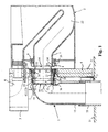
- the connecting device 1 shown in FIG. 1 serves to connect a WC body 2 to a disposal line 23, which passes as a downpipe through a building floor 21.
- the toilet body 2 has a siphon 22 and a horizontal back leading away Outgoing pipe socket 7 and is, for example, with a merely indicated here Cistern 3 rinsed.
- This cistern 3 has a rinsing 6, by the at a flushing water is passed into the toilet body 2.
- the rinse water leaves the toilet body 2 through the outlet pipe socket 7 and passes through the connecting device. 1 in the disposal line 23.
- the toilet body 2 is usually made of ceramic and attached to a frame 5 merely indicated here.
- a planking 4 is arranged here in particular a lightweight wall is and has a breakthrough 24, through which a first front End 25 of the connection device 1 passes.
- the sanitary body can also be one another body with a drain, such as a urinal bowl.
- the connection device 1 has a wastewater connection pipe 15, which has a 90 ° arc forms and the inside in a horizontal mouth region 26 Sealant 16, in particular having a sealing ring.
- this mouth region 26 has a circumferential stop shoulder thirteenth on.
- a separately manufactured component 10 is used, which with a Edge 27 abuts against the stop 13 and that with the sealant 16 against the Wastewater connection pipe 15 is sealed.
- the component 10 the circular cylindrical formed and made of a suitable plastic is made, has an extension 28 which forms an annular space 29 in the one Fire protection material 11 is inserted.
- a Sealing collar 30 is placed, which closes the annular space 29 to the outside and the component 10 seals against a connecting piece 8.
- the gasket As can be seen, 30 is at a distance from the edge 27 and is essentially flush with an outside 31 of the planking 4.
- the fire protection material 11 is inflatable, for example, by heat and preferably meets the fire safety requirements F90.
- connection piece 8 has at one rear side an edge 33, which at a Stop ring 12 rests, which is fastened in the region of the edge 27 on the component 10.
- an extension 20 to which a Sealing collar 9 is fitted, which the connecting piece 8 against the Outgoing pipe socket of the toilet body 2 seals.
- a shoulder 34 of the connecting piece 8 abuts an edge 35 of the outlet pipe socket 7.
- An unexpanded circular cylindrical portion 32 of the connecting piece 8 extends as can be seen through the opening 24 therethrough.
- the connecting device 1 thus consists of three separately manufactured parts, namely the sewage connection pipe 15, the component 10 and the connecting piece 8.
- component 10 can also according to a variant not shown here in one piece on Wastewater connection pipe 15 integrally formed or with this example, with a mirror welding be firmly connected.
- the Mouth 26 behind the seal 16 on the outside a groove 14, in which a pipe clamp 36 is inserted, which connects the connecting device 1 with the frame 5.
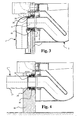
- connection device 1 shown in Figure 2 largely corresponds to the connection device 1, but here has a straight and horizontally wegracedes wastewater connection pipe 17 on.
- the connecting device 1 'goes through a wall opening here 19 a massive building wall 18 through.
- the gasket is 30, which seals the component 10 with respect to the connecting piece 8, flush with an inside 37 of the building wall 18.
- the fire protection material 11 is located behind this inside 37 in the breakthrough 19th
- the fire protection material 11 may be formed as desired, is suitable here in particular a per se known intumescent material which is at a predetermined Temperature expands. Basically, but here are other means of closure possible.
- the stop shoulder 13 and by the stop ring 12 is ensured that the fire protection material 11 is arranged at the appropriate position in the opening 24 is and also the necessary length of the connecting piece 8 is present.
- the stop ring 12 determines the minimum insertion depth of the connecting piece 8 in the opening 24th or 19. If fire protection is not required, then the connecting piece 8 and the fire protection material 11 are omitted.
- the outlet pipe socket 7 is then inserted directly into the component 10 and the sleeve seal 30 seals the component 10 from the outlet pipe socket 7 from. In principle, the component 10 could also be omitted and the sewage connection pipe 15 directly to the outlet pipe socket 7 are connected.
- FIG. 3 shows a connection device 1 ", in which a component 38 is provided, which has on the inside a sealing means 39, for example a sealing ring, which rests against the outside of the sealing sleeve 8.
- the sealant 39 is seen in the flow direction after the fire protection material 11 and forms for this one more protection.
- connection device 1 also has another fire protection material 40, the the outside of the component 38 is arranged and which is also annular and the component 38 surrounds.
- the fire protection material 40 serves as a further securing means. Exists in the planking 4 on the outside of the component 38 accidentally not removablegespachtelte Installation seam 41, so this is sealed in the event of fire from the fire protection material 40.
- the Fire protection material 40 preferably also has an intumescent agent which expands at a predetermined temperature.
- the connecting device 1 '' 'shown in FIG. 4 essentially corresponds to that according to Figure 3, in which case a straight sewage connecting pipe 15 and a building wall 18 are provided.
Landscapes
- Health & Medical Sciences (AREA)
- Life Sciences & Earth Sciences (AREA)
- Engineering & Computer Science (AREA)
- Hydrology & Water Resources (AREA)
- Public Health (AREA)
- Water Supply & Treatment (AREA)
- Sanitary Device For Flush Toilet (AREA)
- Sink And Installation For Waste Water (AREA)
- Residential Or Office Buildings (AREA)
- Buildings Adapted To Withstand Abnormal External Influences (AREA)
Abstract
Description
- Figur 1
- ein Schnitt durch eine erfindungsgemässe Anschlussvorrichtung an einem montierten und hier lediglich abschnittweise gezeigter Klosettanlage und
- Figur 2
- eine Darstellung gemäss Figur 1, jedoch mit einer Variante der erfindungsgemässen Anschlussvorrichtung.
- Figur 3
- eine Anschlussvorrichtung nach einer weiteren Variante und
- Figur 4
- eine Anschlussvorrichtung nach einer weiteren Variante.
- 1.
- Anschlussvorrichtung
- 2.
- WC-Körper
- 3.
- Spülkasten
- 4.
- Beplankung
- 5.
- Gestell
- 6.
- Spülbogen
- 7.
- Abgangs-Rohrstutzen
- 8.
- Verbindungsstutzen
- 9.
- Dichtungsmanschette
- 10.
- Bauteil
- 11.
- Brandschutzmaterial
- 12.
- Anschlagring
- 13.
- Anschlagschulter
- 14.
- Nut
- 15.
- Abwasser-Anschlussrohr
- 16.
- Dichtungsring
- 17.
- Abwasseranschlussrohr
- 18.
- Gebäudewand
- 19.
- Wanddurchbruch
- 20.
- Erweiterung
- 21.
- Gebäudeboden
- 22.
- Siphon
- 23.
- Entsorgungsleitung
- 24.
- Durchbruch
- 25.
- erstes Ende
- 26.
- Mündungsbereich
- 27.
- Kante
- 28.
- Erweiterung
- 29.
- Ringraum
- 30.
- Dichtungsmanschette
- 31.
- Aussenseite
- 32.
- Bereich
- 33.
- Kante
- 34.
- Schulter
- 35.
- Kante
- 36.
- Rohrschelle
- 37.
- Innenseite
- 38.
- Bauteil
- 39.
- Dichtungsmittel
- 40.
- weiteres Brandschutzmaterial
- 41.
- Einbaufuge
Claims (18)
- Anschlussvorrichtung für Sanitärkörper, die an einem ersten Ende an einen Abgangs-Rohrstutzen (7) des Sanitärkörpers (2) und an einem zweiten Ende an eine Entsorgungsleitung (23) anzuschliessen ist, dadurch gekennzeichnet, dass am genannten ersten Ende Brandschutzmittel (11) angeordnet sind, die einen Verbindungsstutzen (8) umgeben, der eine Verlängerung dieses ersten Endes bildet und der an den Abgangs-Rohrstutzen (7) anzuschliessen ist.
- Vorrichtung nach Anspruch 1, dadurch gekennzeichnet, dass am genannten ersten Ende eine Aufweitung (28) angeordnet ist, die innenseitig einen Ringraum (29) bildet, in welchem das Brandschutzmaterial (11) angeordnet ist.
- Vorrichtung nach Anspruch 1 oder 2, dadurch gekennzeichnet, dass der Verbindungsstutzen (8) wenigstens an einem Ende ablängbar ist.
- Vorrichtung nach Anspruch 3, dadurch gekennzeichnet, dass der Verbindungsstutzen (8) ein Dichtungsmittel (9) insbesondere eine Dichtungsmanschette aufweist, welche den Verbindungsstutzen (8) gegen den Abgangs-Rohrstutzen (7) des WC-Körpers (2) abdichtet.
- Vorrichtung nach einem der Ansprüche 1 bis 4, dadurch gekennzeichnet, dass das Brandschutzmaterial (11) in einem separat hergestellten Bauteil (10, 38) angeordnet ist, welches ein Ende des Verbindungsstutzens (8) aufnimmt.
- Vorrichtung nach Anspruch 5, dadurch gekennzeichnet, dass das separat hergestellte Bauteil (10, 38) anschlagbegrenzt in ein Abwasser-Anschlussrohr (15) eingeschoben ist.
- Vorrichtung nach Anspruch 5 oder 6, dadurch gekennzeichnet, dass das separat hergestellte Bauteil (10, 38) fest und insbesondere durch Spiegelschweissung am Abwasser-Anschlussrohr (15) befestigt ist.
- Vorrichtung nach einem der Ansprüche 5 bis 7, dadurch gekennzeichnet, dass das separat hergestellte Bauteil (10) bis zu einem Anschlag (13) in das Abwasser-Anschlussrohr (15) eingeschoben ist.
- Vorrichtung nach Anspruch 7 oder 8, dadurch gekennzeichnet, dass das Abwasser-Anschlussrohr (15) eine angeformte Anschlagschulter (13) zur Positionierung des separat hergestellten Bauteils (10) aufweist.
- Vorrichtung nach Anspruch 8 oder 9, dadurch gekennzeichnet, dass der Anschlag für das separat hergestellte Bauteil (10) so angeordnet ist, dass er eine minimale Ablängung und Einstecktiefe des separat hergestellten Bauteils (10) bestimmt.
- Vorrichtung nach einem der Ansprüche 1 bis 11, dadurch gekennzeichnet, dass das Brandschutzmaterial (11) unmittelbar hinter einem Dichtungsmittel (30) und insbesondere hinter einer Dichtungsmanschette angeordnet ist.
- Vorrichtung nach einem der Ansprüche 1 bis 12, dadurch gekennzeichnet, dass das Brandschutzmaterial (11) unter Wärmeeinwirkung aufblähbar ist.
- Vorrichtung nach Anspruch 12, dadurch gekennzeichnet, dass das Brandschutzmaterial (11) die Brandschutzanforderung F90 erfüllt.
- Einrichtung mit einem an einer Gebäudewand montierten Sanitärkörper, insbesondere WC- oder Urinalkörper, sowie mit einer Anschlussvorrichtung nach Anspruch 1, dadurch gekennzeichnet, dass das Brandschutzmaterial (11) in einem Durchbruch (24, 19) einer Gebäudewand (4, 18) angeordnet ist.
- Einrichtung nach Anspruch 14, dadurch gekennzeichnet, dass der Verbindungsstutzen (8) eine Vorderseite (31, 37) der Gebäudewand (4, 18) überragt und mit einem hinteren Ende in den Durchbruch (24, 19) hineinragt.
- Einrichtung nach Anspruch 14 oder 15, dadurch gekennzeichnet, dass am Verbindungsstutzen (8) aussenseitig ein Dichtungsmittel (30) anliegt, das im Wesentlichen bündig zu einer Vorderseite (31, 37) der Gebäudewand (4, 18) ist.
- Einrichtung nach einem der Ansprüche 5 bis 16, dadurch gekennzeichnet, dass das Bauteil (38) innenseitig Dichtungsmittel (38) angeordnet sind, welche das Brandschutzmaterial (11) nach aussen abdichtet.
- Einrichtung nach einem der Ansprüche 5 bis 17, dadurch gekennzeichnet, dass am Bauteil (38) aussenseitig ein weiteres Brandschutzmaterial (40) zur Abdichtung einer möglichen Einbaufuge (41) angeordnet ist.
Priority Applications (2)
| Application Number | Priority Date | Filing Date | Title |
|---|---|---|---|
| AT03405929T ATE543958T1 (de) | 2003-12-30 | 2003-12-30 | Einrichtung mit einem an einer gebäudewand montiertem sanitärkörper |
| EP03405929A EP1550775B1 (de) | 2003-12-30 | 2003-12-30 | Einrichtung mit einem an einer Gebäudewand montiertem Sanitärkörper |
Applications Claiming Priority (1)
| Application Number | Priority Date | Filing Date | Title |
|---|---|---|---|
| EP03405929A EP1550775B1 (de) | 2003-12-30 | 2003-12-30 | Einrichtung mit einem an einer Gebäudewand montiertem Sanitärkörper |
Publications (2)
| Publication Number | Publication Date |
|---|---|
| EP1550775A1 true EP1550775A1 (de) | 2005-07-06 |
| EP1550775B1 EP1550775B1 (de) | 2012-02-01 |
Family
ID=34560257
Family Applications (1)
| Application Number | Title | Priority Date | Filing Date |
|---|---|---|---|
| EP03405929A Expired - Lifetime EP1550775B1 (de) | 2003-12-30 | 2003-12-30 | Einrichtung mit einem an einer Gebäudewand montiertem Sanitärkörper |
Country Status (2)
| Country | Link |
|---|---|
| EP (1) | EP1550775B1 (de) |
| AT (1) | ATE543958T1 (de) |
Cited By (1)
| Publication number | Priority date | Publication date | Assignee | Title |
|---|---|---|---|---|
| EP2105544A1 (de) | 2008-03-27 | 2009-09-30 | Geberit Technik Ag | Brandschutzelement für eine Sanitäreinrichtung, Sanitäreinrichtung mit einem solchen Brandschutzelement und Brandverschluss-Set für eine Sanitäreinrichtung |
Citations (4)
| Publication number | Priority date | Publication date | Assignee | Title |
|---|---|---|---|---|
| US4453354A (en) * | 1979-11-16 | 1984-06-12 | Harbeke Gerold J | Pipe support coupling and method of using same |
| DE8810562U1 (de) | 1988-08-20 | 1988-10-27 | Mero-Werke Dr.-Ing. Max Mengeringhausen GmbH & Co, 8700 Würzburg | Anschluß-Bauteilesatz für Sanitärkörper, insbesondere WC-Körper |
| US4918761A (en) * | 1988-06-02 | 1990-04-24 | Harbeke Gerold J | Method of using a toilet-flange cast-in mount |
| EP1229175A2 (de) * | 2001-01-31 | 2002-08-07 | Franz Viegener II GmbH & Co. KG. | Ablauf |
-
2003
- 2003-12-30 EP EP03405929A patent/EP1550775B1/de not_active Expired - Lifetime
- 2003-12-30 AT AT03405929T patent/ATE543958T1/de active
Patent Citations (4)
| Publication number | Priority date | Publication date | Assignee | Title |
|---|---|---|---|---|
| US4453354A (en) * | 1979-11-16 | 1984-06-12 | Harbeke Gerold J | Pipe support coupling and method of using same |
| US4918761A (en) * | 1988-06-02 | 1990-04-24 | Harbeke Gerold J | Method of using a toilet-flange cast-in mount |
| DE8810562U1 (de) | 1988-08-20 | 1988-10-27 | Mero-Werke Dr.-Ing. Max Mengeringhausen GmbH & Co, 8700 Würzburg | Anschluß-Bauteilesatz für Sanitärkörper, insbesondere WC-Körper |
| EP1229175A2 (de) * | 2001-01-31 | 2002-08-07 | Franz Viegener II GmbH & Co. KG. | Ablauf |
Cited By (1)
| Publication number | Priority date | Publication date | Assignee | Title |
|---|---|---|---|---|
| EP2105544A1 (de) | 2008-03-27 | 2009-09-30 | Geberit Technik Ag | Brandschutzelement für eine Sanitäreinrichtung, Sanitäreinrichtung mit einem solchen Brandschutzelement und Brandverschluss-Set für eine Sanitäreinrichtung |
Also Published As
| Publication number | Publication date |
|---|---|
| EP1550775B1 (de) | 2012-02-01 |
| ATE543958T1 (de) | 2012-02-15 |
Similar Documents
| Publication | Publication Date | Title |
|---|---|---|
| EP2067901B2 (de) | Einrichtung mit einer Spülvorrichtung und einem Klosettkörper, Montageset zum Montieren einer solchen Einrichtung sowie Verfahren zum Montieren der genannten Einrichtung | |
| EP3913155A1 (de) | Bauschutzvorrichtung für an einer sanitärkeramik anzuschliessende rohrleitungen sowie montagegestell für eine sanitärkeramik mit einer solchen bauschutzvorrichtung | |
| EP2105544B1 (de) | Sanitäreinrichtung mit einem Brandschutzelement | |
| EP4185751A1 (de) | Bauschutz und vorwandelement mit bauschutz | |
| EP1550775B1 (de) | Einrichtung mit einem an einer Gebäudewand montiertem Sanitärkörper | |
| EP1447485A2 (de) | Ablaufeinrichtung | |
| DE202006020903U1 (de) | Installationsvorrichtung für eine sanitäre Einrichtung und sanitäre Einrichtung mit einer solchen Installationsvorrichtung | |
| EP1453574B1 (de) | Brandschutzablauf | |
| DE202020003130U1 (de) | Bauschutz und Vorwandelement mit Bauschutz | |
| EP1605109A1 (de) | Klosettschüssel für ein WC | |
| DE20220498U1 (de) | Bodenablauf | |
| DE20302159U1 (de) | Bauelement für den Brandschutz einer Ablaufvorrichtung sowie Ablaufvorrichtung mit einem derartigen Bauelement | |
| DE102005036464B3 (de) | Geruchsverschluss | |
| EP3913154A1 (de) | Bauschutzvorrichtung für an einer sanitärkeramik anzuschliessende rohrleitungen sowie montagegestell für eine sanitärkeramik mit einer solchen bauschutzvorrichtung | |
| EP3575661B1 (de) | Spül- und probenahmevorrichtung für einen wasserhausanschluss | |
| EP2101001A2 (de) | Einbaukasten mit schlauchgeführten Anschlüssen für eine Sanitärarmatur | |
| EP0814208A2 (de) | Rohrbogen für eine Entsorgungsleitung | |
| EP1136629B1 (de) | Sanitär-Spülarmatur | |
| EP1154084A2 (de) | Wandhängendes Becken | |
| EP0581734A1 (de) | Abwasserleitungsmodul | |
| DE10114076B4 (de) | Verbindungsstück für eine Wasserinstallation | |
| EP0843051B1 (de) | Ab- und Überlaufeinrichtung für Bade- und Duschwannen sowie Verfahren zur Montage einer solchen Einrichtung | |
| DE102024104073A1 (de) | Wandeinbau-Spülkasten mit Leckageschutz | |
| EP3770348A1 (de) | Montageblock | |
| EP4030011A1 (de) | Teleskopierbarer wc-anschluss |
Legal Events
| Date | Code | Title | Description |
|---|---|---|---|
| PUAI | Public reference made under article 153(3) epc to a published international application that has entered the european phase |
Free format text: ORIGINAL CODE: 0009012 |
|
| AK | Designated contracting states |
Kind code of ref document: A1 Designated state(s): AT BE BG CH CY CZ DE DK EE ES FI FR GB GR HU IE IT LI LU MC NL PT RO SE SI SK TR |
|
| AX | Request for extension of the european patent |
Extension state: AL LT LV MK |
|
| 17P | Request for examination filed |
Effective date: 20050802 |
|
| AKX | Designation fees paid |
Designated state(s): AT BE BG CH CY CZ DE DK EE ES FI FR GB GR HU IE IT LI LU MC NL PT RO SE SI SK TR |
|
| 17Q | First examination report despatched |
Effective date: 20080407 |
|
| RAP1 | Party data changed (applicant data changed or rights of an application transferred) |
Owner name: GEBERIT INTERNATIONAL AG |
|
| GRAP | Despatch of communication of intention to grant a patent |
Free format text: ORIGINAL CODE: EPIDOSNIGR1 |
|
| RTI1 | Title (correction) |
Free format text: ARRANGEMENT WITH A SANITARY DEVICE MOUNTED ON A BUILDING WALL |
|
| GRAS | Grant fee paid |
Free format text: ORIGINAL CODE: EPIDOSNIGR3 |
|
| GRAA | (expected) grant |
Free format text: ORIGINAL CODE: 0009210 |
|
| AK | Designated contracting states |
Kind code of ref document: B1 Designated state(s): AT BE BG CH CY CZ DE DK EE ES FI FR GB GR HU IE IT LI LU MC NL PT RO SE SI SK TR |
|
| REG | Reference to a national code |
Ref country code: GB Ref legal event code: FG4D Free format text: NOT ENGLISH |
|
| REG | Reference to a national code |
Ref country code: CH Ref legal event code: EP Ref country code: CH Ref legal event code: NV Representative=s name: ISLER & PEDRAZZINI AG Ref country code: AT Ref legal event code: REF Ref document number: 543958 Country of ref document: AT Kind code of ref document: T Effective date: 20120215 |
|
| REG | Reference to a national code |
Ref country code: DE Ref legal event code: R096 Ref document number: 50314201 Country of ref document: DE Effective date: 20120329 |
|
| REG | Reference to a national code |
Ref country code: NL Ref legal event code: VDEP Effective date: 20120201 |
|
| PG25 | Lapsed in a contracting state [announced via postgrant information from national office to epo] |
Ref country code: NL Free format text: LAPSE BECAUSE OF FAILURE TO SUBMIT A TRANSLATION OF THE DESCRIPTION OR TO PAY THE FEE WITHIN THE PRESCRIBED TIME-LIMIT Effective date: 20120201 |
|
| REG | Reference to a national code |
Ref country code: IE Ref legal event code: FD4D |
|
| PG25 | Lapsed in a contracting state [announced via postgrant information from national office to epo] |
Ref country code: GR Free format text: LAPSE BECAUSE OF FAILURE TO SUBMIT A TRANSLATION OF THE DESCRIPTION OR TO PAY THE FEE WITHIN THE PRESCRIBED TIME-LIMIT Effective date: 20120502 Ref country code: PT Free format text: LAPSE BECAUSE OF FAILURE TO SUBMIT A TRANSLATION OF THE DESCRIPTION OR TO PAY THE FEE WITHIN THE PRESCRIBED TIME-LIMIT Effective date: 20120601 Ref country code: FI Free format text: LAPSE BECAUSE OF FAILURE TO SUBMIT A TRANSLATION OF THE DESCRIPTION OR TO PAY THE FEE WITHIN THE PRESCRIBED TIME-LIMIT Effective date: 20120201 |
|
| PG25 | Lapsed in a contracting state [announced via postgrant information from national office to epo] |
Ref country code: CY Free format text: LAPSE BECAUSE OF FAILURE TO SUBMIT A TRANSLATION OF THE DESCRIPTION OR TO PAY THE FEE WITHIN THE PRESCRIBED TIME-LIMIT Effective date: 20120201 |
|
| PG25 | Lapsed in a contracting state [announced via postgrant information from national office to epo] |
Ref country code: SI Free format text: LAPSE BECAUSE OF FAILURE TO SUBMIT A TRANSLATION OF THE DESCRIPTION OR TO PAY THE FEE WITHIN THE PRESCRIBED TIME-LIMIT Effective date: 20120201 Ref country code: EE Free format text: LAPSE BECAUSE OF FAILURE TO SUBMIT A TRANSLATION OF THE DESCRIPTION OR TO PAY THE FEE WITHIN THE PRESCRIBED TIME-LIMIT Effective date: 20120201 Ref country code: IE Free format text: LAPSE BECAUSE OF FAILURE TO SUBMIT A TRANSLATION OF THE DESCRIPTION OR TO PAY THE FEE WITHIN THE PRESCRIBED TIME-LIMIT Effective date: 20120201 Ref country code: RO Free format text: LAPSE BECAUSE OF FAILURE TO SUBMIT A TRANSLATION OF THE DESCRIPTION OR TO PAY THE FEE WITHIN THE PRESCRIBED TIME-LIMIT Effective date: 20120201 Ref country code: CZ Free format text: LAPSE BECAUSE OF FAILURE TO SUBMIT A TRANSLATION OF THE DESCRIPTION OR TO PAY THE FEE WITHIN THE PRESCRIBED TIME-LIMIT Effective date: 20120201 Ref country code: DK Free format text: LAPSE BECAUSE OF FAILURE TO SUBMIT A TRANSLATION OF THE DESCRIPTION OR TO PAY THE FEE WITHIN THE PRESCRIBED TIME-LIMIT Effective date: 20120201 Ref country code: SE Free format text: LAPSE BECAUSE OF FAILURE TO SUBMIT A TRANSLATION OF THE DESCRIPTION OR TO PAY THE FEE WITHIN THE PRESCRIBED TIME-LIMIT Effective date: 20120201 |
|
| PG25 | Lapsed in a contracting state [announced via postgrant information from national office to epo] |
Ref country code: IT Free format text: LAPSE BECAUSE OF FAILURE TO SUBMIT A TRANSLATION OF THE DESCRIPTION OR TO PAY THE FEE WITHIN THE PRESCRIBED TIME-LIMIT Effective date: 20120201 Ref country code: SK Free format text: LAPSE BECAUSE OF FAILURE TO SUBMIT A TRANSLATION OF THE DESCRIPTION OR TO PAY THE FEE WITHIN THE PRESCRIBED TIME-LIMIT Effective date: 20120201 |
|
| PLBE | No opposition filed within time limit |
Free format text: ORIGINAL CODE: 0009261 |
|
| STAA | Information on the status of an ep patent application or granted ep patent |
Free format text: STATUS: NO OPPOSITION FILED WITHIN TIME LIMIT |
|
| 26N | No opposition filed |
Effective date: 20121105 |
|
| REG | Reference to a national code |
Ref country code: DE Ref legal event code: R097 Ref document number: 50314201 Country of ref document: DE Effective date: 20121105 |
|
| PG25 | Lapsed in a contracting state [announced via postgrant information from national office to epo] |
Ref country code: ES Free format text: LAPSE BECAUSE OF FAILURE TO SUBMIT A TRANSLATION OF THE DESCRIPTION OR TO PAY THE FEE WITHIN THE PRESCRIBED TIME-LIMIT Effective date: 20120512 |
|
| PG25 | Lapsed in a contracting state [announced via postgrant information from national office to epo] |
Ref country code: BG Free format text: LAPSE BECAUSE OF FAILURE TO SUBMIT A TRANSLATION OF THE DESCRIPTION OR TO PAY THE FEE WITHIN THE PRESCRIBED TIME-LIMIT Effective date: 20120501 Ref country code: MC Free format text: LAPSE BECAUSE OF NON-PAYMENT OF DUE FEES Effective date: 20121231 |
|
| GBPC | Gb: european patent ceased through non-payment of renewal fee |
Effective date: 20121230 |
|
| REG | Reference to a national code |
Ref country code: DE Ref legal event code: R082 Ref document number: 50314201 Country of ref document: DE Representative=s name: HOEGER, STELLRECHT & PARTNER PATENTANWAELTE, DE Ref country code: DE Ref legal event code: R082 Ref document number: 50314201 Country of ref document: DE Representative=s name: HOEGER, STELLRECHT & PARTNER PATENTANWAELTE MB, DE |
|
| REG | Reference to a national code |
Ref country code: FR Ref legal event code: ST Effective date: 20130830 |
|
| PG25 | Lapsed in a contracting state [announced via postgrant information from national office to epo] |
Ref country code: GB Free format text: LAPSE BECAUSE OF NON-PAYMENT OF DUE FEES Effective date: 20121230 Ref country code: FR Free format text: LAPSE BECAUSE OF NON-PAYMENT OF DUE FEES Effective date: 20130102 |
|
| REG | Reference to a national code |
Ref country code: AT Ref legal event code: MM01 Ref document number: 543958 Country of ref document: AT Kind code of ref document: T Effective date: 20121230 |
|
| PG25 | Lapsed in a contracting state [announced via postgrant information from national office to epo] |
Ref country code: TR Free format text: LAPSE BECAUSE OF FAILURE TO SUBMIT A TRANSLATION OF THE DESCRIPTION OR TO PAY THE FEE WITHIN THE PRESCRIBED TIME-LIMIT Effective date: 20120201 |
|
| PG25 | Lapsed in a contracting state [announced via postgrant information from national office to epo] |
Ref country code: AT Free format text: LAPSE BECAUSE OF NON-PAYMENT OF DUE FEES Effective date: 20121230 Ref country code: LU Free format text: LAPSE BECAUSE OF NON-PAYMENT OF DUE FEES Effective date: 20121230 |
|
| PG25 | Lapsed in a contracting state [announced via postgrant information from national office to epo] |
Ref country code: HU Free format text: LAPSE BECAUSE OF FAILURE TO SUBMIT A TRANSLATION OF THE DESCRIPTION OR TO PAY THE FEE WITHIN THE PRESCRIBED TIME-LIMIT Effective date: 20031230 |
|
| REG | Reference to a national code |
Ref country code: DE Ref legal event code: R082 Ref document number: 50314201 Country of ref document: DE Representative=s name: HOEGER, STELLRECHT & PARTNER PATENTANWAELTE MB, DE |
|
| PGFP | Annual fee paid to national office [announced via postgrant information from national office to epo] |
Ref country code: BE Payment date: 20171219 Year of fee payment: 15 |
|
| REG | Reference to a national code |
Ref country code: DE Ref legal event code: R082 Ref document number: 50314201 Country of ref document: DE Representative=s name: HOEGER, STELLRECHT & PARTNER PATENTANWAELTE MB, DE |
|
| REG | Reference to a national code |
Ref country code: BE Ref legal event code: MM Effective date: 20181231 |
|
| PG25 | Lapsed in a contracting state [announced via postgrant information from national office to epo] |
Ref country code: BE Free format text: LAPSE BECAUSE OF NON-PAYMENT OF DUE FEES Effective date: 20181231 |
|
| PGFP | Annual fee paid to national office [announced via postgrant information from national office to epo] |
Ref country code: DE Payment date: 20191210 Year of fee payment: 17 |
|
| PGFP | Annual fee paid to national office [announced via postgrant information from national office to epo] |
Ref country code: CH Payment date: 20191211 Year of fee payment: 17 |
|
| REG | Reference to a national code |
Ref country code: DE Ref legal event code: R119 Ref document number: 50314201 Country of ref document: DE |
|
| REG | Reference to a national code |
Ref country code: CH Ref legal event code: PL |
|
| PG25 | Lapsed in a contracting state [announced via postgrant information from national office to epo] |
Ref country code: LI Free format text: LAPSE BECAUSE OF NON-PAYMENT OF DUE FEES Effective date: 20201231 Ref country code: DE Free format text: LAPSE BECAUSE OF NON-PAYMENT OF DUE FEES Effective date: 20210701 Ref country code: CH Free format text: LAPSE BECAUSE OF NON-PAYMENT OF DUE FEES Effective date: 20201231 |