EP2105223A1 - Bandgießmaschine mit Gießwalzenpositionierung - Google Patents
Bandgießmaschine mit Gießwalzenpositionierung Download PDFInfo
- Publication number
- EP2105223A1 EP2105223A1 EP09002876A EP09002876A EP2105223A1 EP 2105223 A1 EP2105223 A1 EP 2105223A1 EP 09002876 A EP09002876 A EP 09002876A EP 09002876 A EP09002876 A EP 09002876A EP 2105223 A1 EP2105223 A1 EP 2105223A1
- Authority
- EP
- European Patent Office
- Prior art keywords
- casting
- strip
- electrical signals
- roll
- rolls
- Prior art date
- Legal status (The legal status is an assumption and is not a legal conclusion. Google has not performed a legal analysis and makes no representation as to the accuracy of the status listed.)
- Withdrawn
Links
Images


Classifications
-
- B—PERFORMING OPERATIONS; TRANSPORTING
- B22—CASTING; POWDER METALLURGY
- B22D—CASTING OF METALS; CASTING OF OTHER SUBSTANCES BY THE SAME PROCESSES OR DEVICES
- B22D11/00—Continuous casting of metals, i.e. casting in indefinite lengths
- B22D11/06—Continuous casting of metals, i.e. casting in indefinite lengths into moulds with travelling walls, e.g. with rolls, plates, belts, caterpillars
- B22D11/0622—Continuous casting of metals, i.e. casting in indefinite lengths into moulds with travelling walls, e.g. with rolls, plates, belts, caterpillars formed by two casting wheels
-
- B—PERFORMING OPERATIONS; TRANSPORTING
- B22—CASTING; POWDER METALLURGY
- B22D—CASTING OF METALS; CASTING OF OTHER SUBSTANCES BY THE SAME PROCESSES OR DEVICES
- B22D11/00—Continuous casting of metals, i.e. casting in indefinite lengths
- B22D11/06—Continuous casting of metals, i.e. casting in indefinite lengths into moulds with travelling walls, e.g. with rolls, plates, belts, caterpillars
- B22D11/0637—Accessories therefor
- B22D11/0697—Accessories therefor for casting in a protected atmosphere
-
- B—PERFORMING OPERATIONS; TRANSPORTING
- B22—CASTING; POWDER METALLURGY
- B22D—CASTING OF METALS; CASTING OF OTHER SUBSTANCES BY THE SAME PROCESSES OR DEVICES
- B22D41/00—Casting melt-holding vessels, e.g. ladles, tundishes, cups or the like
- B22D41/12—Travelling ladles or similar containers; Cars for ladles
Definitions
- This invention relates to the casting of metal strip by continuous casting in a twin roll caster.
- molten metal is introduced between a pair of counter-rotated horizontal casting rolls that are cooled so that metal shells solidify on the moving roll surfaces and are brought together at a nip between them to produce a solidified strip product, delivered downwardly from the nip between the rolls.
- the term "nip" is used herein to refer to the general region at which the rolls are closest together.
- the molten metal may be poured from a ladle into a smaller vessel or series of smaller vessels from which it flows through a metal delivery nozzle located above the nip, so forming a casting pool of molten metal supported on the casting surfaces of the rolls immediately above the nip and extending along the length of the nip. This casting pool is usually confined between side plates or dams held in sliding engagement with end surfaces of the rolls so as to dam the two ends of the casting pool against outflow.
- twin roll caster may be capable of continuously producing cast strip from molten steel through a sequence of ladles. Pouring the molten metal from the ladle into smaller vessels before flowing through the metal delivery nozzle enables the exchange of an empty ladle with a full ladle without disrupting the production of cast strip.
- the casting rolls must be accurately set to properly define an appropriate width for the nip, generally of the order of a few millimeters or less. There must also be some means for allowing at least one of the rolls to move relative to the other casting roll to accommodate fluctuations in strip thickness, particularly during start up.
- one of the casting rolls was mounted in fixed journals or was mounted in supports urged against physical stops.
- the other casting roll was rotatably mounted on supports that could move outwardly against the action of a resisting force enabling that roll to move laterally to accommodate fluctuations in strip thickness.
- the resisting force was applied by helical compression springs, or alternatively, pressure fluid cylinder units.
- a strip caster with spring resisting force against the laterally moveable roll is disclosed in U.S. Pat. No. 6,167,943 to Fish et al.
- the resistive springs act between roll supports and a pair of thrust reaction structures, the positions of which can be set by operation of a pair of powered mechanical jacks to enable adjustment of the initial compression of the springs to set initial compression forces.
- the initial compression forces are generally equal at both ends of the roll.
- the positions of the roll supports on the moveable casting roll are subsequently adjusted after commencement of casting, so that the gap between the rolls is constant across the width of the nip to produce a strip of constant profile.
- U.S. Pat. No. 6,167,943 does not provide strip thickness profile control to suppress thickness profile fluctuations during casting.
- U.S. Pat. No. 6,837,301 to Nikolovski, et al. provides for controlling strip thickness profile during casting using sensors positioned downstream of the nip.
- U.S. Pat. No. 6,837,301 discloses strip thickness profile control obtained by enabling one of the casting rolls to move laterally outward from the other casting roll against variable resistive forces. The other casting roll is maintained substantially fixed against an adjustable stop.
- An apparatus for continuously casting thin steel strip comprising:
- Each casting roll may be mounted on a roll cassette, and may further include actuators disconnectable from the casting rolls to enable the casting rolls to be changed out without dismantling the actuators.
- each casting roll By independently moving, each casting roll is able to move toward and away from the reference location and the nip between the casting rolls. There are reaction forces on the casting rolls from the cast strip and the movement of the adjacent casting roll, but these reaction forces are forces to which the independent movement of the casting rolls is responsive.
- actuators are provided capable of independently moving each casting roll relative to the given reference location, although with mechanical linkage it may be possible to provide independent movement of the casting rolls with one actuator mechanism.
- the actuators may also be provided to vary the distance between the casting rolls at each end of the casting rolls independently as desired.
- the actuators may be selected from the group consisting of servo-mechanisms, hydraulic mechanisms, pneumatic mechanisms, rotating actuators and magnetostrictive actuators, and be capable of moving the casting rolls independently to vary the distance between each casting roll and the given reference location.
- the apparatus for continuously casting strip may also have separate location sensors capable of sensing the position of the casting rolls relative to the given reference location at each end of each casting roll independently.
- the apparatus for continuously casting strip may further include force sensors capable of sensing the forces exerted on the strip adjacent the nip and producing electrical signals indicative of forces exerted on the strip.
- the control system may be also capable of receiving the electrical signals indicative of the sensed forces exerted on the strip and causing the actuator to move the casting rolls responsive to the sensed forces exerted on the strip as desired.
- the control system may capable of receiving and combining the separate electrical signals indicative of the sensed forces exerted on the strip from each end of each casting roll, and causing one or more actuators to vary the position of the casting rolls responsive to the combined electrical signals.
- the control system may be capable of receiving the electrical signals indicative of the sensed forces exerted on the strip and combining the electrical signals from an end of one casting roll with the electrical signals from the corresponding end of the other casting roll and causing one or more actuators to vary the position of the casting rolls responsive to the combined electrical signals.
- control system may be capable of receiving the electrical signals indicative of the sensed forces exerted on the strip and combining the electrical signals from opposite ends of one casting roll and causing the actuators to vary the position of the casting rolls responsive to the combined electrical signals.
- the apparatus for continuously casting strip may also include profile sensors positioned downstream of the nip capable of sensing the strip thickness profile at a plurality of locations along the strip width and producing electrical signals indicative of the strip thickness profile downstream of the nip, and the control system capable of processing the electrical signals indicative of the strip thickness profile and causing the actuator to move the casting rolls responsive to the electrical signals and further control the thickness profile of the cast strip responsive to the electrical signals indicative of the strip thickness profile.
- the apparatus for continuously casting strip may include temperature profile sensors positioned downstream of the nip capable of sensing the strip temperature profile at a plurality of locations along the strip width, and producing electrical signals indicative of the strip temperature profile downstream of the nip.
- the temperature profile sensors may be positioned to determine the temperatures across the cast strip at segments adjacent the nip or further downstream of the nip, and generate electrical signals corresponding to the strip temperature profile in segments across the strip adjacent the nip.
- the control system may be capable of processing the electrical signals indicative of the strip temperature profile, and causing the actuators to move the casting rolls and further control the thickness profile of the cast strip responsive to the electrical signals indicative of the strip temperature profile.
- Also disclosed is a method of continuously casting metal strip comprising the steps of:
- Each casting roll may be mounted on a roll cassette, with each casting roll being mounted to be capable of moving toward and away from the nip during casting.
- the method may include the step of separately moving each casting roll relative to the given reference location. Alternately or in addition, the method may further include the steps of:
- the moving step may be performed by one or more actuators.
- the actuator or actuators are selected from the group consisting of servo-mechanisms, hydraulic mechanisms, pneumatic mechanisms, rotating actuators, and magnetostrictive actuators, and are capable of moving the casting rolls independently to vary the distance between each casting roll and the given reference location.
- the moving step may be performed by independently varying the distance between the casting rolls at each end of the casting rolls. Alternately or in addition, the moving step is performed by controlling a force urging each roll against the thin cast strip there between during casting.
- the method may include the additional step of disconnecting the casting rolls to enable the casting rolls to be changed out without dismantling the actuators.
- a twin roll caster is illustrated that comprises a main machine frame 10 that stands up from the factory floor and supports a pair of casting rolls mounted in a module in a roll cassette 11.
- the casting rolls 12 are mounted in the roll cassette 11 for ease of operation and movement as described below.
- the roll cassette facilitates rapid movement of the casting rolls ready for casting from a setup position into an operative casting position in the caster as a unit, and ready removal of the casting rolls from the casting position when the casting rolls are to be replaced.
- There is no particular configuration of the roll cassette that is desired, so long as it performs that function of facilitating movement and positioning of the casting rolls as described herein.
- the casting apparatus for continuously casting thin steel strip includes a pair of counter-rotatable casting rolls 12 having casting surfaces 12A laterally positioned to form a nip 18 there between.
- Molten metal is supplied from a ladle 13 through a metal delivery system to a metal delivery nozzle 17, or core nozzle, positioned between the casting rolls 12 above the nip 18.
- Molten metal thus delivered forms a casting pool 19 of molten metal above the nip supported on the casting surfaces 12A of the casting rolls 12.
- This casting pool 19 is confined in the casting area at the ends of the casting rolls 12 by a pair of side closures or side dam plates 20 (shown in dotted line in FIG. 3 ).
- the upper surface of the casting pool 19 (generally referred to as the "meniscus" level) may rise above the lower end of the delivery nozzle 17 so that the lower end of the delivery nozzle is immersed within the casting pool.
- the casting area includes the addition of a protective atmosphere above the casting pool 19 to inhibit oxidation of the molten metal in the casting area.
- the ladle 13 typically is of a conventional construction supported on a rotating turret 40.
- the ladle 13 is positioned over a movable tundish 14 in the casting position to fill the tundish with molten metal.
- the movable tundish 14 may be positioned on a tundish car 66 capable of transferring the tundish from a heating station 69, where the tundish is heated to near a casting temperature, to the casting position.
- a tundish guide 70 positioned beneath the tundish car 66 to enable moving the movable tundish 14 from the heating station 69 to the casting position.
- the tundish car 66 may include a frame 71 having a tundish support beam 72 engaging tundish arms 75 on each side of the tundish 14.
- the tundish support beams 72 may be positioned between lifters 73, 74 capable of raising and lowering the tundish support beam 72 and the tundish 14 relative to the frame 71 to position the tundish 14 on the tundish car 66.
- the tundish guide may include rails 76 extending between the heating station and the casting position, and the tundish car 66 may include wheels 77 assembled to move on the rails 76.
- One or more drive motors 79 may be used to drive the wheels 77 along the rails.
- the rails 76 may extend between two heating stations 69 in either direction away from the casting position, and capable of supporting two tundish cars 66, so that one tundish car may be in one of the heating stations 69 while another tundish car is in the casting position. After casting is stopped, the tundish 14 in the casting position may be moved on the first tundish car in the direction away from the second tundish car to its respective heating station.
- the tundish car typically moves between the casting position to the heating station at an elevation above the casting rolls 12 mounted in roll cassette 11, and at least a portion of the tundish guide 70 may be overhead from the elevation of the casting rolls 12 mounted on roll cassette 11 for movement of the tundish between the heating station and the casting position.
- the movable tundish 14 may be fitted with a slide gate 25, actuable by a servo mechanism, to allow molten metal to flow from the tundish 14 through the slide gate 25, and then through a refractory outlet shroud 15 to a transition piece or distributor 16 in the casting position. From the distributor 16, the molten metal flows to the delivery nozzle 17 positioned between the casting rolls 12 above the nip 18.
- the casting rolls 12 are internally water cooled so that as the casting rolls 12 are counter-rotated, shells solidify on the casting surfaces 12A as the casting surfaces move into contact with and through the casting pool 19 with each revolution of the casting rolls 12.
- the shells are brought together at the nip 18 between the casting rolls to produce a solidified thin cast strip product 21 delivered downwardly from the nip.
- FIG. 1 shows the twin roll caster producing the thin cast strip 21, which passes across a guide table 30 to a pinch roll stand 31, comprising pinch rolls 31A.
- the thin cast strip may pass through a hot rolling mill 32, comprising a pair of reduction rolls 32A and backing rolls 32B, where the cast strip is hot rolled to reduce the strip to a desired thickness, improve the strip surface, and improve the strip flatness.
- the rolled strip then passes onto a run-out table 33, where it may be cooled by contact with water supplied via water jets or other suitable means, not shown, and by convection and radiation.
- the rolled strip may then pass through a second pinch roll stand (not shown) to provide tension of the strip, and then to a coiler.
- a short length of imperfect strip is typically produced as casting conditions stabilize.
- the casting rolls are moved apart slightly and then brought together again to cause this leading end of the strip to break away forming a clean head end of the following cast strip.
- the imperfect material drops into a scrap receptacle 26, which is movable on a scrap receptacle guide.
- the scrap receptacle 26 is located in a scrap receiving position beneath the caster and forms part of a sealed enclosure 27 as described below.
- the enclosure 27 is typically water cooled.
- a water-cooled apron 28 that normally hangs downwardly from a pivot 29 to one side in the enclosure 27 is swung into position to guide the clean end of the cast strip 21 onto the guide table 30 that feeds it to the pinch roll stand 31.
- the apron 28 is then retracted back to its hanging position to allow the cast strip 21 to hang in a loop beneath the casting rolls in enclosure 27 before it passes to the guide table 30 where it engages a succession of guide rollers.
- An overflow container 38 may be provided beneath the movable tundish 14 to receive molten material that may spill from the tundish. As shown in FIGS. 1 and 2 , the overflow container 38 may be movable on rails 39 or another guide such that the overflow container 38 may be placed beneath the movable tundish 14 as desired in casting locations. Additionally, an overflow container may be provided for the distributor 16 adjacent the distributor (not shown).
- the sealed enclosure 27 is formed by a number of separate wall sections that fit together at various seal connections to form a continuous enclosure wall that permits control of the atmosphere within the enclosure. Additionally, the scrap receptacle 26 may be capable of attaching with the enclosure 27 so that the enclosure is capable of supporting a protective atmosphere immediately beneath the casting rolls 12 in the casting position.
- the enclosure 27 includes an opening in the lower portion of the enclosure, lower enclosure portion 44, providing an outlet for scrap to pass from the enclosure 27 into the scrap receptacle 26 in the scrap receiving position.
- the lower enclosure portion 44 may extend downwardly as a part of the enclosure 27, the opening being positioned above the scrap receptacle 26 in the scrap receiving position.
- a rim portion 45 may surround the opening of the lower enclosure portion 44 and may be movably positioned above the scrap receptacle, capable of sealingly engaging and/or attaching to the scrap receptacle 26 in the scrap receiving position.
- the rim portion 45 is in selective engagement with the upper edges of the scrap receptacle 26, which is illustratively in a rectangular form, so that the scrap receptacle may be in sealing engagement with the enclosure 27.
- the rim portion may be movable away from or otherwise disengage from the scrap receptacle to disengage the seal and allow the scrap receptacle to move from the scrap receiving position.
- a lower plate 46 may be operatively positioned within or adjacent the lower enclosure portion 44 to permit further control of the atmosphere within the enclosure when the scrap receptacle 26 is moved from the scrap receiving position and provide an opportunity to continue casting while the scrap receptacle is being changed for another.
- the lower plate 46 may be operatively positioned within the enclosure 27 capable of closing the opening of the lower portion of the enclosure, or lower enclosure portion 44, when the rim portion 45 is disengaged from the scrap receptacle. Then, the lower plate 46 may be retracted when the rim portion 45 sealingly engages the scrap receptacle to enable scrap material to pass downwardly through the enclosure 27 into the scrap receptacle 26. As shown in FIGS.
- the lower plate 46 may be in two plate portions, pivotably mounted to move between a retracted position and a closed position. Alternately, the lower plate 46 may be one moveable plate portion.
- a plurality of actuators such as servo-mechanisms, hydraulic mechanisms, pneumatic mechanisms and rotating actuators may be suitably positioned outside of the enclosure 27, and capable of moving the lower plate in whatever configuration between a closed position and a retracted position. The plurality of actuators may be provided to rotate the lower plate 46 about a pivot.
- the lower plate 46 may be movable laterally along a guide, such as one or more rails between a closed position closing the lower enclosure portion 44 and a retracted position enabling scrap material to pass downwardly through the enclosure 27 into the scrap receptacle 26.
- a guide such as one or more rails between a closed position closing the lower enclosure portion 44 and a retracted position enabling scrap material to pass downwardly through the enclosure 27 into the scrap receptacle 26.
- the actuators are positioned outside of the enclosure 27 and capable of moving the upper collar portion 43 between an extended and an open position.
- the upper collar portion 43 may be raised into the extended position in sealing engagement with the housing portion 53, which may or may not be part of the roll cassette 11, and be able to support the protective atmosphere in enclosure 27 immediately beneath the casting rolls in the casting position.
- the upper collar portion 43 may also be lowered into the open position disengaged from housing portion 53 enabling the upper cover 42 to move into its closed position beneath the casting rolls and covering the upper portion of the enclosure 27 as described below.
- the upper collar portion 43 may be water cooled.
- the upper cover 42 may be operatively moved into closed position at the upper portion of the enclosure 27 beneath the casting rolls to permit further control of the protective atmosphere within the enclosure when the casting rolls are removed from the casting position.
- the upper cover 42 may be operably positioned within or adjacent the upper portion of the enclosure 27 capable of moving between a closed position covering the enclosure and a retracted position enabling cast strip to be cast downwardly from the nip into the enclosure 27.
- the roll cassette 11 may be moved from the casting position without significant loss of the protective atmosphere in the enclosure. This enables a rapid exchange of casting rolls, with the roll cassette, since closing the upper cover 42 enables the protective atmosphere in the enclosure to be preserved so that it does not have to be replaced.
- One or more actuators 59 such as servo-mechanisms, hydraulic mechanisms, pneumatic mechanisms, and rotating actuators, may be provided to move the upper cover 42 between the closed position and open position.
- the upper cover in the closed position enables the roll cassette 11 to be moved from the casting position without substantial degradation of the protective atmosphere in the enclosure 27.
- the upper cover may then be retracted when the casting rolls, typically in the roll cassette 11, are to be moved into the casting position, and the upper collar portion 43 moved to its extended position to support the protective atmosphere in the enclosure 27, as shown in FIG. 3 , so that cast strip may be cast downwardly from the nip between the casting rolls and pass into the enclosure 27.
- the upper cover 42 may be capable of engaging the upper collar portion 43 and closing the enclosure 27. Alternately, the upper cover 42 may be in two or more portions capable of closing the enclosure 27.
- the upper cover 42 may be movable laterally along guides, such as a pair of rails 64 as shown in FIGS. 3 and 7 , and the actuator 59 capable of moving the upper cover along the guides between the closed position and the retracted position. Alternately the upper cover 42 may rotated about a pivot, or with other motion, to move between a retracted position and a closed position. In any case, the actuator 59 is capable of moving the upper cover between the closed position and the retracted position.
- the casting rolls 12 mounted in roll cassette 11 are capable of being transferred from a set up station 47 to a casting position through a transfer station 48, as shown in FIGS. 2 and 8 .
- the casting rolls 12 may be assembled into the roll cassette 11 and then moved to the set up station 47, where at the set up station the casting rolls mounted in the roll cassette are capable of being prepared for casting.
- casting rolls mounted in roll cassettes are capable of being exchanged, and in the casting position the casting rolls mounted in the roll cassette are operational in the caster.
- a casting roll guide is adapted to enable the transfer of the casting rolls mounted in the roll cassette between the set up station and the transfer station, and between the transfer station and the casting position.
- the casting rolls mounted in a roll cassette may be raised or lowered into the casting position.
- the casting roll guides may comprise rails on which the casting rolls 12 mounted in the roll cassette 11 are capable of being moved between the set up station and the casting position through the transfer station.
- First rails 55 may extend between the set up station 47 to the transfer station 48
- second rails 56 may extend between the transfer station 48 to the casting position.
- the second rails 56 may extend to the casting position from either side of the casting position.
- the second rails 56 may extend from the casting position in two directions with a second transfer station and a second setup station with rails corresponding to the first rail from both setup stations to the transfer station, such that the casting rolls 12 mounted in roll cassettes 11 may arrive in the casting position from either of two directions.
- the casting roll guides may move casting rolls mounted in the roll cassette from either transfer station to the casting position at substantially the same elevation as the casting rolls when in the casting position.
- the casting roll guides may move the casting rolls mounted in the roll cassette from the set up station to the transfer station at substantially the same elevation or different elevations.
- the first rails 55 are at a different elevation than the second rails 56, and the transfer station 48 may move between the different elevations to move casting rolls 12 mounted in roll cassettes 11 between the first rails 55 and second rails 56.
- the casting roll guides may be, if needed, enable locking engagement of positioning assemblies with the roll cassette 11 on the casting roll guides.
- the roll cassette 11 may include wheels 54 capable of supporting and moving the roll cassette on the rails 55, 56. As shown in FIGS. 3 and 7 , the wheels 54 may have a portion that engages the rail to enable to the wheel to stay on the rail. Alternately or in addition, the rail may have a portion that engages the wheel to enable the wheel to stay on the rail.
- the casting roll guides may include a propulsion system (not shown) capable of moving the roll cassette 11 along the rails 55, 56.
- the roll cassette 11 may include at least a portion of the propulsion system capable of moving the roll cassette 11, the portion capable of driving the wheels 54 or capable of cooperating with a corresponding portion of the propulsion device of the casting roll guide.
- the propulsion system may include, for example, cog and drive chain, pulley and cable, drive screw and screw jack, rack and pinion, linear actuators, hydraulic or pneumatic cylinders, hydraulic or pneumatic actuators, electric motors, or other devices capable of moving the roll cassette 11 along the rails 55, 56.
- the casting rolls mounted in the roll cassette are capable of being prepared for casting at the set up station 47. Initial casting roll position on the roll cassette and other adjustments may be made when the casting rolls are prepared for casting.
- the set up station 47 may be position on the first rails 55. Alternately, the set up station 47 may be separate from the first rails 55 and at the same or a different elevation than the first rails 55.
- the transfer station 48 may include a turntable 58.
- Both first and second rails 55, 56 may be capable of being aligned with rails on the turntable 58 of the transfer station such that the turntable 58 may be turned to exchange casting rolls mounted in roll cassettes between the first rails 55 and the second rails 56.
- the turntable 58 may rotate about a center axis, as indicated by arrow "A" in FIG. 8 , to transfer a roll cassette from one set of rails to another. As shown in FIG.
- the turntable 58 may include at least two rail portions, each capable of holding a set of casting rolls mounted a roll cassette and each aligned with a set of rails 55, 56 extending there from, such that when the turntable rotates about its central axis, the casting rolls mounted on the roll cassettes on the turntable move from being aligned with one set of rails to another.
- the turntable 58 shown in FIG. 8 is generally configured to transfer two sets of casting rolls mounted on roll cassettes at the same time, but the transfer station may be configured to be capable of transferring three, or more sets of casting rolls mounted in roll cassettes as desired to service one or more twin roll casters at the same time.
- the transfer station 48 may include a shifting platform (not shown) where both first and second rails 55, 56 may be capable of being aligned with rails on the shifting platform. In this event, the shifting platform may then translate horizontally, vertically, or laterally to move casting rolls mounted in roll cassettes between the first rails 55 and the second rails 56.
- the roll cassette 11 with casting rolls may be assembled in a module for rapid installation in the caster in preparation for casting strip, and for rapid set up of the casting rolls 12 for installation.
- the roll cassette 11 comprises a cassette frame 52, roll chocks 49 capable of supporting the casting rolls 12 and moving the casting rolls on the cassette frame, and the housing portion 53 positioned beneath the casting rolls capable of supporting a protective atmosphere in the enclosure 27 immediately beneath the casting rolls during casting.
- the housing portion 53 is positioned corresponding to and sealingly engaging an upper portion of the enclosure 27 for enclosing the cast strip below the nip.
- a roll chock positioning system is provided on the main machine frame 10 having two pairs of positioning assemblies 51 that can be rapidly connected to the roll cassette adapted to enable movement of the casting rolls on the cassette frame 52, and provide forces resisting separation of the casting rolls during casting.
- the positioning assemblies 51 may include actuators such as mechanical roll biasing units or servo-mechanisms, hydraulic or pneumatic cylinders or mechanisms, linear actuators, rotating actuators, magnetostrictive actuators or other devices for enabling movement of the casting rolls and resisting separation of the casting rolls during casting.
- the casting rolls 12 may be about 500 millimeters in diameter, or may be up to 1200 millimeters or more in diameter.
- the length of the casting rolls 12 may be up to about 2000 millimeters, or longer, in order to enable production of strip product of about 2000 millimeters width, or wider, as desired in order to produce strip product approximately the width of the rolls.
- the casting surfaces may be textured with a distribution of discrete projections, for example, as random discrete projections as described and claimed in U.S. Patent No. 7,073,565 .
- the casting surface may be coated with chrome, nickel, or other coating material to protect the texture.
- cleaning brushes 36 are disposed adjacent the pair of casting rolls, such that the periphery of the cleaning brushes 36 may be brought into contact with the casting surfaces 12A of the casting rolls 12 to clean oxides from the casting surfaces during casting.
- the cleaning brushes 36 are positioned at opposite sides of the casting area adjacent the casting rolls, between the nip 18 and the casting area where the casting rolls enter the protective atmosphere in contact with the molten metal casting pool 19.
- a separate sweeper brush 37 may be provided for further cleaning the casting surfaces 12A of the casting rolls 12, for example at the beginning and end of a casting campaign as desired.
- a knife seal 65 may be provided adjacent each casting roll 12 and adjoining the housing portion 53.
- the knife seals 65 may be positioned as desired near the casting roll and forming a partial closure between the housing portion 53 and the rotating casting rolls 12.
- the knife seals 65 enable control of the atmosphere around the brushes, and reduce the passage of hot gases from the enclosure 27 around the casting rolls.
- the knife seals 65 may be positioned 3 to 4 millimeters from the casting surface 12A, as desired, when in casting position.
- the position of each knife seal 65 may be adjustable during casting by causing actuators such as hydraulic or pneumatic cylinders to move the knife seal toward or away from the casting rolls. Alternately, the knife seals 65 may be positioned prior to casting and not adjustable during casting.
- the casing rolls are secured with the positioning assemblies 51 connected to the roll cassette 11, drive shafts connected to the end couplings 23, and a supply of cooling water coupled to water supply hoses 24.
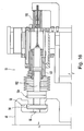
- a plurality of jacks 57 may be used to further place the casting rolls in operating position.
- the jacks 57 may raise the roll cassette 11 in the casting position, as shown in FIG. 3 .
- the roll cassette may be lowered or laterally moved in the casting position to place the casting rolls in operating position.
- the positioning assemblies 51 may move at least one of the casting rolls 12 to provide a desired nip, or gap between the rolls in the casting position.
- positioning assembly 51 has a flange 94 capable of engaging the roll cassette 11.
- the positioning assembly 51 may be secured to the roll cassette in cooperation with shaft 96.
- the shaft 96 may be positioned by an actuator (not shown) moving in and out within the roll chock 49, and secure the positioning assembly 51 by pressing the flange 94 against a corresponding surface 98 of the roll cassette 11.
- the positioning assembly 51 includes a first actuator 100.
- the first actuator 100 may be capable of moving a thrust element 102 in connection with the flange 94.
- a force sensor or load cell 104 may be positioned between the thrust element 102 and the flange 94.
- the load cell 104 is positioned capable of sensing forces urging the casting roll 12 against the thin cast strip casting between the casting rolls 12 and providing an electrical signal indicative of the sensed force exerted on the strip adjacent the nip.
- a first location sensor 106 is provided with the positioning assembly 51 to determine the position of the thrust element 102, and thereby the position of the flange 94 and the roll chock 49 secured thereto.
- the first location sensor 106 provides electrical signals to the control system indicative of the position of the roll chock 49 and associated casting roll 12 relative to a given reference location.
- a positioning assembly 50 having a compression spring may be provided to control one of the casting rolls.
- the positioning assembly 50 has a flange 112 capable of engaging the roll cassette 11.
- the positioning assembly 50 may be secured to the roll cassette by a flange cylinder 114.
- the flange cylinder 114 is engaged to secure the flange 112 against a corresponding surface 116 of the roll cassette 11.
- the positioning assembly 50 may include a second actuator 118 capable of moving a thrust element 120 in connection with the flange 112.
- a force sensor or load cell 108 may be positioned between the thrust element 120 and the flange 112.
- the load cell 108 is positioned capable of sensing forces urging the casting roll 12 against the thin cast strip casting between the casting rolls 12 and providing an electrical signal indicative of the sensed force exerted on the strip adjacent the nip.
- Positioning assembly 50 may include an additional load cell capable of measuring the spring compression force.
- adjustable stops were provided between the casting rolls limiting inward movement and defining the minimum width of the nip, where one casting roll was maintained against the adjustable stop and the other casting roll was capable of outward movement against resistive forces, such as against the compression spring 124 in the second actuator 118.
- neither casting roll is pressed against a physical stop during casting.
- the position of both casting rolls may be varied independently toward and away from the nip and a given reference location.
- stops are appropriate only as a fail safe to avoid the casting rolls from coming together and being damaged.
- a reference location is determined, and the actuators 100, and optionally actuators 118, move each casting roll independently toward and away from the given reference location as desired.
- a reference location may be determined for each casting roll, with a known relationship there between. In any event, the position of each casting roll is determined relative to the given reference location, and thereby the position of each casting roll relative to the other casting roll may also be determined.
- the location sensors 106, 130 may be linear displacement sensors, such as for example but not limited to voltage differential transducers, variable inductance transducers, variable capacitance transducers, eddy current transducers, magnetic displacement sensors, optical displacement sensors, or other displacement sensors capable of sensing the location of the casting rolls 12 relative to the given reference location and producing electrical signals indicative of each casting roll position in relation to the given reference location.
- linear displacement sensors such as for example but not limited to voltage differential transducers, variable inductance transducers, variable capacitance transducers, eddy current transducers, magnetic displacement sensors, optical displacement sensors, or other displacement sensors capable of sensing the location of the casting rolls 12 relative to the given reference location and producing electrical signals indicative of each casting roll position in relation to the given reference location.
- the control system is capable of receiving the electrical signals indicative of the casting roll positions and causing the actuators to move the casting rolls 12 into desired position for casting metal strip. Additionally, the control system may control the position of each end of each casting roll 12 independently by causing the two pair of actuators to vary independently the distance between the casting rolls at each end of the casting rolls, or to vary the distance between each end of the casting rolls and the given reference location.
- the force sensors may be positioned at each end of each casting roll, and the control system capable of receiving the electrical signals indicative of the sensed forces exerted on the strip from each end of each casting roll separately and causing each actuator to vary the distance between each end of the casting rolls and the given reference location responsive to the electrical signals as desired.
- the control system is capable of processing the electrical signals from the force sensors 104 indicative of the forces exerted on the strip, and controlling the position of the casting rolls 12 responsive to the signals from the load cells 104, 108 to maintain a desired force urging the casting roll 12 against the thin cast strip.
- the control system may control the position of each end of each casting roll 12 independently responsive to the electrical signals from the load cells 104, 108.
- profile sensors may be positioned downstream of the nip capable of sensing the strip thickness profile at a plurality of locations along the strip width, and producing electrical signals indicative of the strip thickness profile downstream of the nip.
- the control system may be capable of processing the electrical signals indicative of the strip thickness profile, and causing the actuators to move the casting rolls and further control the thickness profile of the cast strip responsive to the electrical signals indicative of the strip thickness profile.
- temperature profile sensors may be positioned downstream of the nip capable of sensing the strip temperature profile at a plurality of locations along the strip width, and producing electrical signals indicative of the strip temperature profile downstream of the nip.
- the temperature profile sensors may be positioned to determine the temperatures across the cast strip at segments adjacent the nip or further downstream of the nip, and generate electrical signals corresponding to the strip temperature profile in segments across the strip adjacent the nip.
- the temperature measurements may be segmented into more than three segments, such as five or more segments, or in a continuum, to provide a strip temperature profile across the cast strip adjacent the nip.
- the control system may control the position of each casting roll 12 separately and by different algorithms.
- the control system may receive the electrical signals indicative of the casting roll's position in relation to the given reference location and cause the actuator to move the first casting roll into a determined position relative to the given reference location. Then, the control system may continue to receive the electrical signals indicative of that casting roll's position, and when the control system determines that the first casting roll is not in the determined position, cause the actuator to move the first casting roll into the determined position.
- the control system may determine that the forces exerted on the strip are higher or lower than desired using combined electrical signals from more than one force sensor or load cell 104 by signal summing, signal averaging, signal differencing, or other signal combining.
- the control system may be capable of receiving and combining the electrical signals indicative of the sensed forces exerted on the strip and causing one or more actuators 100 to vary the position of the casting rolls responsive to the combined electrical signals.
- the control system may be capable of combining the separate electrical signals indicative of the sensed forces exerted on the strip from each end of each casting roll, by combining the electrical signals from force sensors or load cells 104 at each end of one casting roll, then combining the separate electrical signals from force sensors or load cells 104 at each end of the other casting roll.
- the control system may be capable of combining the electrical signals from force sensors or load cells 104 at an end of one casting roll with the electrical signals from the corresponding end of the other casting roll.
- the electrical signals from the force sensors or load cells from both ends of one casting roll will be combined by signal summing to provide a combined electrical signal indicative of the total force exerted by that casting roll. It is contemplated, however, that various control algorithms may be used, including for example but not limited to:
- the nip 18 between the casting rolls may be positioned relative to the metal delivery nozzle 17 as desired.
- the control system is capable of moving both casting rolls independently.
- the control system is capable of causing the actuators 100 to move the position of the nip 18 relative to the metal delivery nozzle 17 by moving both casting rolls.
Landscapes
- Engineering & Computer Science (AREA)
- Mechanical Engineering (AREA)
- Continuous Casting (AREA)
Applications Claiming Priority (1)
| Application Number | Priority Date | Filing Date | Title |
|---|---|---|---|
| US3771408P | 2008-03-19 | 2008-03-19 |
Publications (1)
| Publication Number | Publication Date |
|---|---|
| EP2105223A1 true EP2105223A1 (de) | 2009-09-30 |
Family
ID=40810230
Family Applications (1)
| Application Number | Title | Priority Date | Filing Date |
|---|---|---|---|
| EP09002876A Withdrawn EP2105223A1 (de) | 2008-03-19 | 2009-02-27 | Bandgießmaschine mit Gießwalzenpositionierung |
Country Status (6)
| Country | Link |
|---|---|
| US (1) | US8002016B2 (de) |
| EP (1) | EP2105223A1 (de) |
| CN (1) | CN102015155B (de) |
| BR (1) | BRPI0909191A2 (de) |
| RU (1) | RU2491149C2 (de) |
| WO (1) | WO2009115877A1 (de) |
Families Citing this family (10)
| Publication number | Priority date | Publication date | Assignee | Title |
|---|---|---|---|---|
| US8322402B2 (en) * | 2009-09-23 | 2012-12-04 | Nucor Corporation | Method and apparatus for controlling strip temperature rebound in cast strip |
| EP2436459A1 (de) * | 2010-09-29 | 2012-04-04 | Siemens Aktiengesellschaft | Vorrichtung und Verfahren zur Positionierung mindestens einer von zwei Gießrollen in einem kontinuierlichen Gießverfahren zur Herstellung eines Metallbands |
| US20120222831A1 (en) * | 2011-03-04 | 2012-09-06 | Nucor Corporation | Method of continuously casting thin strip |
| CN102658295B (zh) * | 2012-04-10 | 2014-11-05 | 辽宁科技大学 | 一种可在线倾翻的双辊铸轧方法及其装置 |
| JP5976087B2 (ja) | 2013-12-24 | 2016-08-23 | ポスコ | 薄板製造装置における鋳造ロールの損傷防止装置 |
| JP6569494B2 (ja) * | 2015-11-18 | 2019-09-04 | 日本製鉄株式会社 | 薄肉鋳片製造設備、及びピンチロールのレベリング方法 |
| EP3546089B1 (de) * | 2016-12-26 | 2020-11-18 | Primetals Technologies Japan, Ltd. | Stranggiessvorrichtung mit doppelter walze |
| CN112236248B (zh) * | 2018-06-12 | 2022-06-03 | 日本制铁株式会社 | 薄壁铸板的制造方法 |
| TW202019582A (zh) * | 2018-10-22 | 2020-06-01 | 日商日本製鐵股份有限公司 | 鑄片的製造方法及控制裝置 |
| CN110625105B (zh) * | 2019-10-23 | 2023-07-14 | 中信戴卡股份有限公司 | 转运设备和铝液转运系统以及铝液转运方法 |
Citations (3)
| Publication number | Priority date | Publication date | Assignee | Title |
|---|---|---|---|---|
| US6167943B1 (en) | 1997-09-18 | 2001-01-02 | Ishikawajima-Harima Heavy Industries Company, Limited | Strip casting apparatus |
| US6837301B2 (en) | 1999-02-05 | 2005-01-04 | Castrip Llc | Strip casting apparatus |
| US7073565B2 (en) | 1999-02-05 | 2006-07-11 | Castrip, Llc | Casting steel strip |
Family Cites Families (81)
| Publication number | Priority date | Publication date | Assignee | Title |
|---|---|---|---|---|
| US3837894A (en) * | 1972-05-22 | 1974-09-24 | Union Carbide Corp | Process for producing a corrosion resistant duplex coating |
| DE2419684C3 (de) | 1974-04-24 | 1981-04-23 | Vereinigte Aluminium-Werke Ag, 5300 Bonn | Verfahren und Vorrichtung zum Kühlen beim Stranggießen von Metall |
| JPS5836650B2 (ja) * | 1978-06-16 | 1983-08-10 | 新日本製鐵株式会社 | 引張強さ35〜50Kg/mm↑2、降伏比60%未満で、高伸びを有する複合組織冷延鋼板の製造方法 |
| DE3009680B1 (de) | 1980-03-11 | 1980-08-28 | Mannesmann Ag | Verfahren zur direkten Kuehlung von Stahlstraengen |
| JPS5927370B2 (ja) * | 1980-07-05 | 1984-07-05 | 新日本製鐵株式会社 | プレス加工用高強度冷延鋼板 |
| US4609410A (en) * | 1980-12-04 | 1986-09-02 | United States Steel Corporation | Method for producing high-strength deep-drawable dual-phase steel sheets |
| US4398970A (en) * | 1981-10-05 | 1983-08-16 | Bethlehem Steel Corporation | Titanium and vanadium dual-phase steel and method of manufacture |
| JPS60174852A (ja) * | 1984-02-18 | 1985-09-09 | Kawasaki Steel Corp | 深絞り性に優れる複合組織冷延鋼板とその製造方法 |
| US4770719A (en) * | 1984-04-12 | 1988-09-13 | Kawasaki Steel Corporation | Method of manufacturing a low yield ratio high-strength steel sheet having good ductility and resistance to secondary cold-work embrittlement |
| DE3562073D1 (en) | 1985-01-18 | 1988-05-11 | Alpine Ag | Pull-off device for tubular plastic films |
| JPH0829401B2 (ja) | 1990-07-05 | 1996-03-27 | 新日本製鐵株式会社 | 薄肉鋳片の連続鋳造方法 |
| JPH0751256B2 (ja) * | 1990-11-22 | 1995-06-05 | 三菱重工業株式会社 | 連鋳機の板厚検出方法および装置 |
| US5470403A (en) * | 1992-06-22 | 1995-11-28 | Nippon Steel Corporation | Cold rolled steel sheet and hot dip zinc-coated cold rolled steel sheet having excellent bake hardenability, non-aging properties and formability, and process for producing same |
| US5328528A (en) * | 1993-03-16 | 1994-07-12 | China Steel Corporation | Process for manufacturing cold-rolled steel sheets with high-strength, and high-ductility and its named article |
| US6044895A (en) * | 1993-12-21 | 2000-04-04 | Siemens Aktiengesellschaft | Continuous casting and rolling system including control system |
| FR2728817A1 (fr) * | 1994-12-29 | 1996-07-05 | Usinor Sacilor | Procede de regulation pour la coulee continue entre cylindres |
| AUPN101495A0 (en) * | 1995-02-10 | 1995-03-09 | Bhp Steel (Jla) Pty Limited | Casting steel strip |
| FR2732627B1 (fr) * | 1995-04-07 | 1997-04-30 | Usinor Sacilor | Procede et dispositif de reglage du bombe des cylindres d'une installation de coulee de bandes metalliques |
| AUPN733095A0 (en) * | 1995-12-22 | 1996-01-25 | Bhp Steel (Jla) Pty Limited | Twin roll continuous caster |
| AUPN872596A0 (en) * | 1996-03-19 | 1996-04-18 | Bhp Steel (Jla) Pty Limited | Strip casting |
| JP3412418B2 (ja) | 1996-10-07 | 2003-06-03 | 住友金属工業株式会社 | 鋳片2次冷却装置 |
| CA2283924C (en) | 1997-03-17 | 2006-11-28 | Nippon Steel Corporation | Dual-phase type high-strength steel sheets having high impact energy absorption properties and a method of producing the same |
| US6164366A (en) * | 1997-05-28 | 2000-12-26 | Ishikawajima-Harima Heavy Industries Company Ltd. | Strip casting apparatus |
| AUPO925397A0 (en) * | 1997-09-18 | 1997-10-09 | Bhp Steel (Jla) Pty Limited | Strip casting apparatus |
| JP3320014B2 (ja) * | 1997-06-16 | 2002-09-03 | 川崎製鉄株式会社 | 耐衝撃特性に優れた高強度高加工性冷延鋼板 |
| DE69813424T2 (de) * | 1997-09-18 | 2004-03-04 | Castrip, Llc | Bandgiessanlage |
| JP3340359B2 (ja) | 1997-09-22 | 2002-11-05 | 日立造船株式会社 | ツインロール型薄板連続鋳造機におけるロール間隔の制御方法およびロール間隔の制御装置 |
| KR100314849B1 (ko) * | 1997-12-24 | 2002-01-15 | 이구택 | 쌍롤형 박판제조 장치에서의 박판두께 제어방법 |
| AT408198B (de) * | 1998-03-25 | 2001-09-25 | Voest Alpine Ind Anlagen | Verfahren zum stranggiessen eines dünnen bandes sowie vorrichtung zur durchführung des verfahrens |
| AUPP406798A0 (en) * | 1998-06-12 | 1998-07-02 | Bhp Steel (Jla) Pty Limited | Strip casting apparatus |
| US6886623B2 (en) * | 1998-06-17 | 2005-05-03 | Castrip Llc | Strip casting apparatus |
| US6942013B2 (en) * | 1998-08-07 | 2005-09-13 | Lazar Strezov | Casting steel strip |
| AUPP852699A0 (en) * | 1999-02-05 | 1999-03-04 | Bhp Steel (Jla) Pty Limited | Strip casting apparatus |
| JP4217847B2 (ja) | 1999-02-17 | 2009-02-04 | 住友金属工業株式会社 | 連続鋳造方法 |
| CA2334672C (en) * | 1999-04-21 | 2009-09-22 | Kawasaki Steel Corporation | High-strength galvanized steel sheet having excellent ductility and manufacturing method thereof |
| US6312536B1 (en) * | 1999-05-28 | 2001-11-06 | Kabushiki Kaisha Kobe Seiko Sho | Hot-dip galvanized steel sheet and production thereof |
| AUPQ291199A0 (en) * | 1999-09-17 | 1999-10-07 | Bhp Steel (Jla) Pty Limited | Strip casting |
| CN1124358C (zh) * | 1999-10-22 | 2003-10-15 | 川崎制铁株式会社 | 加工性及锌可镀性均优良的高强度热浸镀锌钢板及其制造方法 |
| AUPQ436299A0 (en) * | 1999-12-01 | 1999-12-23 | Bhp Steel (Jla) Pty Limited | Casting steel strip |
| US6641931B2 (en) * | 1999-12-10 | 2003-11-04 | Sidmar N.V. | Method of production of cold-rolled metal coated steel products, and the products obtained, having a low yield ratio |
| DE60133493T2 (de) * | 2000-01-24 | 2009-05-07 | Jfe Steel Corp. | Feuerverzinktes Stahlblech und Verfahren zu dessen Herstellung |
| WO2001062997A1 (fr) * | 2000-02-23 | 2001-08-30 | Kawasaki Steel Corporation | Feuille d'acier resistant a une traction elevee, laminee a chaud et dotee d'excellentes proprietes de resistance au durcissement, au vieillissement et a la deformation et procede de fabrication associe |
| KR100595946B1 (ko) * | 2000-02-29 | 2006-07-03 | 제이에프이 스틸 가부시키가이샤 | 변형 시효 경화특성이 우수한 고장력 냉연 강판 및 그제조 방법 |
| CN1295353C (zh) * | 2000-04-07 | 2007-01-17 | 川崎制铁株式会社 | 具有优良应变时效硬化特性的钢板的制造方法 |
| WO2001090431A1 (fr) | 2000-05-26 | 2001-11-29 | Kawasaki Steel Corporation | Tole d'acier laminee a froid et tole d'acier galvanisee possedant des proprietes de durcissement par ecrouissage et par precipitation et procede de production associe |
| US6988530B2 (en) * | 2000-06-15 | 2006-01-24 | Castrip Llc | Strip casting |
| JP3958921B2 (ja) * | 2000-08-04 | 2007-08-15 | 新日本製鐵株式会社 | 塗装焼付硬化性能と耐常温時効性に優れた冷延鋼板及びその製造方法 |
| JP4542247B2 (ja) * | 2000-08-08 | 2010-09-08 | キャストリップ・リミテッド・ライアビリティ・カンパニー | ストリップ連続鋳造装置及びその使用方法 |
| KR20020017028A (ko) | 2000-08-28 | 2002-03-07 | 이구택 | 쌍롤형 박판주조 제어장치 및 방법 |
| US6673171B2 (en) * | 2000-09-01 | 2004-01-06 | United States Steel Corporation | Medium carbon steel sheet and strip having enhanced uniform elongation and method for production thereof |
| ATE438470T1 (de) * | 2000-09-29 | 2009-08-15 | Nucor Corp | Herstellung von dünnem stahlblech |
| CN1193110C (zh) * | 2000-11-28 | 2005-03-16 | 川崎制铁株式会社 | 高强度双相薄钢板和高强度双相电镀薄钢板及其制造方法 |
| JP4085583B2 (ja) * | 2001-02-27 | 2008-05-14 | Jfeスチール株式会社 | 高強度冷延溶融亜鉛メッキ鋼板およびその製造方法 |
| CA2387322C (en) * | 2001-06-06 | 2008-09-30 | Kawasaki Steel Corporation | High-ductility steel sheet excellent in press formability and strain age hardenability, and method for manufacturing the same |
| TWI290177B (en) * | 2001-08-24 | 2007-11-21 | Nippon Steel Corp | A steel sheet excellent in workability and method for producing the same |
| EP1288322A1 (de) * | 2001-08-29 | 2003-03-05 | Sidmar N.V. | Ultrahochfester Stahl, Produkt aus diesem Stahl und Verfahren zu seiner Herstellung |
| PL197123B1 (pl) | 2001-09-13 | 2008-03-31 | Properties Ak | Sposób wytwarzania taśmy ze stali elektrotechnicznej o zorientowanym ziarnie |
| FR2830260B1 (fr) * | 2001-10-03 | 2007-02-23 | Kobe Steel Ltd | Tole d'acier a double phase a excellente formabilite de bords par etirage et procede de fabrication de celle-ci |
| US6709535B2 (en) * | 2002-05-30 | 2004-03-23 | Kobe Steel, Ltd. | Superhigh-strength dual-phase steel sheet of excellent fatigue characteristic in a spot welded joint |
| US20040238082A1 (en) * | 2002-06-14 | 2004-12-02 | Jfe Steel Corporation | High strength cold rolled steel plate and method for production thereof |
| US20040003774A1 (en) * | 2002-07-03 | 2004-01-08 | Moore B. L. | Continuous galvanizing system |
| ITMI20021510A1 (it) * | 2002-07-10 | 2004-01-12 | Danieli Off Mecc | Impianto per la colata continua di nastro metallico |
| ITMI20021505A1 (it) * | 2002-07-10 | 2004-01-12 | Danieli Off Mecc | Dispositivo di supporto di rulli per colata continua di nastro metallico |
| RU2253541C2 (ru) * | 2002-07-16 | 2005-06-10 | Бакуменко Сергей Пантелеевич | Установка для получения тонких полос |
| JP3764411B2 (ja) * | 2002-08-20 | 2006-04-05 | 株式会社神戸製鋼所 | 焼付硬化性に優れた複合組織鋼板 |
| US20040047756A1 (en) * | 2002-09-06 | 2004-03-11 | Rege Jayanta Shantaram | Cold rolled and galvanized or galvannealed dual phase high strength steel and method of its production |
| US7311789B2 (en) * | 2002-11-26 | 2007-12-25 | United States Steel Corporation | Dual phase steel strip suitable for galvanizing |
| US6811624B2 (en) * | 2002-11-26 | 2004-11-02 | United States Steel Corporation | Method for production of dual phase sheet steel |
| US20040206471A1 (en) * | 2003-04-18 | 2004-10-21 | Blejde Walter N. | Casting steel strip |
| AT412539B (de) * | 2003-05-06 | 2005-04-25 | Voest Alpine Ind Anlagen | Zweiwalzengiesseinrichtung |
| TWI290586B (en) * | 2003-09-24 | 2007-12-01 | Nippon Steel Corp | Hot rolled steel sheet and method of producing the same |
| JP4635525B2 (ja) * | 2003-09-26 | 2011-02-23 | Jfeスチール株式会社 | 深絞り性に優れた高強度鋼板およびその製造方法 |
| JP4325998B2 (ja) * | 2004-05-06 | 2009-09-02 | 株式会社神戸製鋼所 | スポット溶接性及び材質安定性に優れた高強度溶融亜鉛めっき鋼板 |
| AT501314B1 (de) * | 2004-10-13 | 2012-03-15 | Voest Alpine Ind Anlagen | Verfahren und vorrichtung zum kontinuierlichen herstellen eines dünnen metallbandes |
| US7442268B2 (en) * | 2004-11-24 | 2008-10-28 | Nucor Corporation | Method of manufacturing cold rolled dual-phase steel sheet |
| US7191819B2 (en) * | 2004-12-07 | 2007-03-20 | Nucor Corporation | Continuously casting steel strip |
| JP4337739B2 (ja) | 2005-01-07 | 2009-09-30 | 住友金属工業株式会社 | 溶鋼の連続鋳造方法 |
| CA2606419A1 (en) * | 2005-04-19 | 2006-10-26 | Plastic Suppliers, Inc. | Polylactic acid shrink films and methods of manufacturing same |
| DE102005054996A1 (de) * | 2005-11-18 | 2007-05-24 | Thyssenkrupp Nirosta Gmbh | Verfahren zum Betrieb einer Zweiwalzengießmaschine zum Vergießen von Metallschmelzen zu gegossenem Band |
| US7464746B2 (en) * | 2006-08-09 | 2008-12-16 | Nucor Corporation | Method of casting thin cast strip |
| UA35617U (en) * | 2008-05-07 | 2008-09-25 | Общество С Ограниченной Ответственностью "Компания "Укравит" | Fungicidal composition |
-
2009
- 2009-02-27 WO PCT/IB2009/000368 patent/WO2009115877A1/en active Application Filing
- 2009-02-27 EP EP09002876A patent/EP2105223A1/de not_active Withdrawn
- 2009-02-27 BR BRPI0909191A patent/BRPI0909191A2/pt not_active IP Right Cessation
- 2009-02-27 RU RU2010142457/02A patent/RU2491149C2/ru not_active IP Right Cessation
- 2009-02-27 CN CN2009801153980A patent/CN102015155B/zh not_active Expired - Fee Related
- 2009-03-16 US US12/404,684 patent/US8002016B2/en not_active Expired - Fee Related
Patent Citations (3)
| Publication number | Priority date | Publication date | Assignee | Title |
|---|---|---|---|---|
| US6167943B1 (en) | 1997-09-18 | 2001-01-02 | Ishikawajima-Harima Heavy Industries Company, Limited | Strip casting apparatus |
| US6837301B2 (en) | 1999-02-05 | 2005-01-04 | Castrip Llc | Strip casting apparatus |
| US7073565B2 (en) | 1999-02-05 | 2006-07-11 | Castrip, Llc | Casting steel strip |
Also Published As
| Publication number | Publication date |
|---|---|
| CN102015155A (zh) | 2011-04-13 |
| BRPI0909191A2 (pt) | 2016-11-01 |
| CN102015155B (zh) | 2013-11-27 |
| US20090236067A1 (en) | 2009-09-24 |
| US8002016B2 (en) | 2011-08-23 |
| RU2010142457A (ru) | 2012-04-27 |
| WO2009115877A1 (en) | 2009-09-24 |
| RU2491149C2 (ru) | 2013-08-27 |
Similar Documents
| Publication | Publication Date | Title |
|---|---|---|
| US8002016B2 (en) | Strip casting apparatus with casting roll positioning | |
| US9120147B2 (en) | Strip casting apparatus for rapid set and change of casting rolls | |
| US9744589B2 (en) | Method and apparatus for controlling variable shell thickness in cast strip | |
| US8322402B2 (en) | Method and apparatus for controlling strip temperature rebound in cast strip | |
| US20090314458A1 (en) | Strip Casting Apparatus with Independent Delivery Nozzle and Side Dam Actuators | |
| US8028741B2 (en) | Strip casting apparatus with improved side dam force control | |
| US7938164B2 (en) | Production of thin steel strip | |
| US20140367065A1 (en) | Thin roll strip caster and method of operating the same | |
| US20140262122A1 (en) | Strip casting apparatus with improved side dam force control | |
| WO2010051590A1 (en) | Strip casting apparatus with improved side dam force control |
Legal Events
| Date | Code | Title | Description |
|---|---|---|---|
| PUAI | Public reference made under article 153(3) epc to a published international application that has entered the european phase |
Free format text: ORIGINAL CODE: 0009012 |
|
| AK | Designated contracting states |
Kind code of ref document: A1 Designated state(s): AT BE BG CH CY CZ DE DK EE ES FI FR GB GR HR HU IE IS IT LI LT LU LV MC MK MT NL NO PL PT RO SE SI SK TR |
|
| AX | Request for extension of the european patent |
Extension state: AL BA RS |
|
| RIN1 | Information on inventor provided before grant (corrected) |
Inventor name: EDWARDS, JAMES D. Inventor name: REES, HAROLD Inventor name: GRUESS, ANSGAR |
|
| 17P | Request for examination filed |
Effective date: 20100330 |
|
| AKX | Designation fees paid |
Designated state(s): AT BE BG CH CY CZ DE DK EE ES FI FR GB GR HR HU IE IS IT LI LT LU LV MC MK MT NL NO PL PT RO SE SI SK TR |
|
| RAP1 | Party data changed (applicant data changed or rights of an application transferred) |
Owner name: NUCOR CORPORATION Owner name: SIEMENS AKTIENGESELLSCHAFT |
|
| STAA | Information on the status of an ep patent application or granted ep patent |
Free format text: STATUS: THE APPLICATION IS DEEMED TO BE WITHDRAWN |
|
| 18D | Application deemed to be withdrawn |
Effective date: 20140902 |