EP2103873A2 - Dispositif pour contrôler un mélange de deux fluides - Google Patents
Dispositif pour contrôler un mélange de deux fluides Download PDFInfo
- Publication number
- EP2103873A2 EP2103873A2 EP09004041A EP09004041A EP2103873A2 EP 2103873 A2 EP2103873 A2 EP 2103873A2 EP 09004041 A EP09004041 A EP 09004041A EP 09004041 A EP09004041 A EP 09004041A EP 2103873 A2 EP2103873 A2 EP 2103873A2
- Authority
- EP
- European Patent Office
- Prior art keywords
- pressure
- burner
- gas
- force
- gases
- Prior art date
- Legal status (The legal status is an assumption and is not a legal conclusion. Google has not performed a legal analysis and makes no representation as to the accuracy of the status listed.)
- Granted
Links
- 239000000203 mixture Substances 0.000 title claims abstract description 74
- 238000012544 monitoring process Methods 0.000 title claims abstract description 28
- 239000012530 fluid Substances 0.000 title claims description 41
- 239000007789 gas Substances 0.000 claims abstract description 71
- 238000006073 displacement reaction Methods 0.000 claims abstract description 40
- 238000000034 method Methods 0.000 claims abstract description 24
- 239000001301 oxygen Substances 0.000 claims description 24
- 229910052760 oxygen Inorganic materials 0.000 claims description 24
- QVGXLLKOCUKJST-UHFFFAOYSA-N atomic oxygen Chemical compound [O] QVGXLLKOCUKJST-UHFFFAOYSA-N 0.000 claims description 22
- 239000002737 fuel gas Substances 0.000 claims description 21
- 239000007788 liquid Substances 0.000 claims description 7
- 230000003068 static effect Effects 0.000 claims description 3
- 238000012937 correction Methods 0.000 claims description 2
- 239000002655 kraft paper Substances 0.000 claims description 2
- 239000003570 air Substances 0.000 claims 1
- 238000006243 chemical reaction Methods 0.000 claims 1
- 239000012528 membrane Substances 0.000 description 20
- 238000012806 monitoring device Methods 0.000 description 13
- 238000002485 combustion reaction Methods 0.000 description 12
- 239000002131 composite material Substances 0.000 description 6
- 238000011144 upstream manufacturing Methods 0.000 description 5
- 238000010304 firing Methods 0.000 description 4
- 239000000446 fuel Substances 0.000 description 4
- ATUOYWHBWRKTHZ-UHFFFAOYSA-N Propane Chemical compound CCC ATUOYWHBWRKTHZ-UHFFFAOYSA-N 0.000 description 2
- 230000033228 biological regulation Effects 0.000 description 2
- 150000001875 compounds Chemical class 0.000 description 2
- 238000013461 design Methods 0.000 description 2
- 238000001514 detection method Methods 0.000 description 2
- 230000007257 malfunction Effects 0.000 description 2
- 238000005259 measurement Methods 0.000 description 2
- VNWKTOKETHGBQD-UHFFFAOYSA-N methane Chemical compound C VNWKTOKETHGBQD-UHFFFAOYSA-N 0.000 description 2
- 238000009530 blood pressure measurement Methods 0.000 description 1
- 239000001273 butane Substances 0.000 description 1
- 230000003247 decreasing effect Effects 0.000 description 1
- 230000002950 deficient Effects 0.000 description 1
- 238000011161 development Methods 0.000 description 1
- 230000018109 developmental process Effects 0.000 description 1
- 230000000694 effects Effects 0.000 description 1
- 238000005516 engineering process Methods 0.000 description 1
- 239000001257 hydrogen Substances 0.000 description 1
- 150000002431 hydrogen Chemical class 0.000 description 1
- 229910052739 hydrogen Inorganic materials 0.000 description 1
- IJDNQMDRQITEOD-UHFFFAOYSA-N n-butane Chemical compound CCCC IJDNQMDRQITEOD-UHFFFAOYSA-N 0.000 description 1
- OFBQJSOFQDEBGM-UHFFFAOYSA-N n-pentane Natural products CCCCC OFBQJSOFQDEBGM-UHFFFAOYSA-N 0.000 description 1
- 239000003345 natural gas Substances 0.000 description 1
- 238000002360 preparation method Methods 0.000 description 1
- 239000001294 propane Substances 0.000 description 1
- 230000001681 protective effect Effects 0.000 description 1
- 238000010186 staining Methods 0.000 description 1
Images

Classifications
-
- F—MECHANICAL ENGINEERING; LIGHTING; HEATING; WEAPONS; BLASTING
- F23—COMBUSTION APPARATUS; COMBUSTION PROCESSES
- F23D—BURNERS
- F23D14/00—Burners for combustion of a gas, e.g. of a gas stored under pressure as a liquid
- F23D14/46—Details, e.g. noise reduction means
- F23D14/72—Safety devices, e.g. operative in case of failure of gas supply
-
- F—MECHANICAL ENGINEERING; LIGHTING; HEATING; WEAPONS; BLASTING
- F23—COMBUSTION APPARATUS; COMBUSTION PROCESSES
- F23N—REGULATING OR CONTROLLING COMBUSTION
- F23N5/00—Systems for controlling combustion
- F23N5/18—Systems for controlling combustion using detectors sensitive to rate of flow of air or fuel
-
- F—MECHANICAL ENGINEERING; LIGHTING; HEATING; WEAPONS; BLASTING
- F23—COMBUSTION APPARATUS; COMBUSTION PROCESSES
- F23N—REGULATING OR CONTROLLING COMBUSTION
- F23N5/00—Systems for controlling combustion
- F23N5/24—Preventing development of abnormal or undesired conditions, i.e. safety arrangements
- F23N5/247—Preventing development of abnormal or undesired conditions, i.e. safety arrangements using mechanical means
-
- F—MECHANICAL ENGINEERING; LIGHTING; HEATING; WEAPONS; BLASTING
- F23—COMBUSTION APPARATUS; COMBUSTION PROCESSES
- F23N—REGULATING OR CONTROLLING COMBUSTION
- F23N5/00—Systems for controlling combustion
- F23N5/18—Systems for controlling combustion using detectors sensitive to rate of flow of air or fuel
- F23N2005/181—Systems for controlling combustion using detectors sensitive to rate of flow of air or fuel using detectors sensitive to rate of flow of air
- F23N2005/182—Air flow switch
-
- F—MECHANICAL ENGINEERING; LIGHTING; HEATING; WEAPONS; BLASTING
- F23—COMBUSTION APPARATUS; COMBUSTION PROCESSES
- F23N—REGULATING OR CONTROLLING COMBUSTION
- F23N5/00—Systems for controlling combustion
- F23N5/18—Systems for controlling combustion using detectors sensitive to rate of flow of air or fuel
- F23N2005/185—Systems for controlling combustion using detectors sensitive to rate of flow of air or fuel using detectors sensitive to rate of flow of fuel
-
- F—MECHANICAL ENGINEERING; LIGHTING; HEATING; WEAPONS; BLASTING
- F23—COMBUSTION APPARATUS; COMBUSTION PROCESSES
- F23N—REGULATING OR CONTROLLING COMBUSTION
- F23N2225/00—Measuring
- F23N2225/04—Measuring pressure
Definitions
- the present invention relates to a device for mixture monitoring for fluid mixtures of two fluids.
- a gas-air or gas-oxygen composite control device must provide a mixture precisely and safely. This can e.g. be realized via a mechanical linkage, a pneumatic version or an electronic composite control devices. In the case of mechanical linkages or pneumatic versions, it is not necessary to carry them out redundantly. Redundant means that safety-related systems are designed in such a way that if one component fails, the other components ensure the corresponding function. This minimizes the risk that these components will be subject to a common fault. Electronic compound control devices operate redundantly, for example with two measurements with safety-related control via a control unit.
- the DIN standards state that the mass air flow to the gas mass flow always has to be in a ratio that can be reliably ignited so as to maintain stable and safe combustion at the burner throughout the operating range.
- the ratio does not have to be the same value under all operating conditions.
- the design and implementation of the air-gas ratio control must take into account both the operating conditions and the properties of the fuel and combustion air. In the event of a fault, the system should tend to produce a higher air surplus or cause a shutdown if the air-gas ratio leads to a non-safe state.
- Pneumatic gas-air composite governors must comply with DIN EN 12067-1.
- Electronic gas-air compound regulators are to be designed and executed according to DIN EN 12067-2.
- gas and air pressure switches must be installed in the flow direction upstream of the control valves but after the last pressure control devices.
- the gas and air pressure monitors each monitor the minimum and maximum pressure and thus ensure a correct air / gas ratio in conjunction with the above-mentioned safe ratio control and a safe minimum and maximum output of the industrial thermal process plant (IThE) in all possible operating states.
- IThE industrial thermal process plant
- pneumatic controllers (DIN EN 12067-1 compliant) are used, additional protective measures should be provided to ensure that the protection system triggers a fault shutdown in the event of malfunction or malfunction of the pneumatic composite governor to achieve an equivalent level of safety as described above ,
- the electronic mixture monitoring is often carried out on single-channel burners with fuel / air mixture or fuel / oxygen mixture and thus not safety-related.
- single-channel mixture controls are electronic devices for mixture control with programmable logic controllers (PLC) as well as flow and / or ratio controls.
- a method of controlling the fuel-air ratio of a fuel-fired burner is described.
- this method is intended to control the flame of the burner and / or the fuel-air ratio of a fuel-fired burner.
- the burner has a burner surface, wherein the electrical resistance or the temperature of the burner or of a measuring element on the side facing away from the flame of the burning surface is detected and serves to monitor the control. If it is determined that the resistance or the temperature of the burner is too high, the mixture is emaciated and greased in the other case.
- From the EP 1 207 340 A2 goes out a method for controlling a gas burner.
- the process provides a functional check of the combined gas / air system to keep the gas / air ratio within a narrow operating range during operation. It is after each burner start, after over ignition of the ignition on the Main burner checks the entire chain of effects in the control loop of the gas / air composite control, so that a calibration takes place at the burner start. The current control parameters are compared with the previous control parameters to determine whether predetermined limits for deviations are exceeded or fallen below.
- the gas heater has an actuator with a mixing ratio of fuel gas and air is adjustable.
- a lambda sensor By means of a lambda sensor, the ratio of air to gas during combustion can be determined via the exhaust gas.
- a control system coupled to the actuator and the lambda sensor permits lambda-controlled control of the actuator, the control system knowing the manipulated variable set on the actuator and the limit values of the manipulated variables that can be set on the actuator.
- the control system calculates a failure time from the chronological progression of the manipulated variable at which the manipulated variable reaches one of its limit values.
- the object of the invention is to provide a simple and inexpensive device for mixture monitoring for fluid mixtures of two fluids, which can be used for all types and sizes of equipment and fuel gases for hedging.
- the object is achieved with a device having the features of claim 1 and a method having the features of claim 10.
- a very simple, mechanical or electromechanical and thus safety-oriented monitoring of the fuel / air or oxygen ratio is not required.
- the simple electromechanical device can be used as a second feedback or protection for safe shutdown of a burner system.
- the device according to the invention is a very simple electromechanical device which can also be used alone to monitor a mixture. In Germany, a special approval and acceptance procedure is required for such an application.
- a leakage within a burner device due to a hose breakage, a defective valve, etc. is detected on the basis of the changing mixture composition and the gas supply is switched off immediately, whereby accidents due to leaks are reliably prevented. Such accidents can be caused by a wrong mixture composition or leaking gas.
- two line sections are provided for the flow of a respective fluid, which are flowed through by them in a flow direction, wherein in each of the two line sections, a flow resistance is arranged and two further pressure / displacement converter are provided, each to the Attacking bar ends to the pressure / Wegwandmin opposite sides of the bar ends, wherein at the two line sections in the flow direction before and after the flow resistance in each case branches off a branch line, which are connected to one of the pressure / Wegwandler, and two branch lines connected to one of the line sections each pressurize a pair of pressure / displacement transducers opposite the beam.
- the pressure difference of a fluid is measured via the flow resistance in the corresponding line section.
- the ratio of the pressure difference of the fluids is largely proportional to the flow ratio of the fluids.
- the bars thus compare the fluid flows.
- the device according to the invention is also suitable for mixture monitoring of liquids and mixtures of liquids and gases.
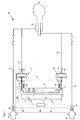
- the inventive device 1 for mixture monitoring for gas mixtures is in FIG. 1 shown together with a burner device.
- the device 1 for mixture monitoring for gas mixtures is referred to below as a monitoring device.
- This monitoring device 1 has a Relative pressure rocker 2 with a stationary, elongated base 3 on.
- a first and a second displaceable supports 4, 5 are arranged on the base 3, a first and a second displaceable supports 4, 5 are arranged.
- On the supports 4, 5 is a bar 6 which is mounted on the supports 4, 5 pivotable or tiltable.
- the supports 4, 5 are displaceable along the longitudinal direction of the base 3.
- the bar 6 is arranged approximately parallel to the longitudinal direction of the base 3.
- the supports 4, 5 allow lifting of the beam from the respective bearings transverse to the longitudinal direction.
- the fixation of the beam 6 in the longitudinal direction can e.g. by a stop formed on the base 3 or by axial bearing of the linkage 17 and 23 and the fixed / movable mounting of the bearings 18 and 24 (not shown).
- the pedestals form stops for the bar ends 9, 10, so that their pivotal movement is limited.
- safety switches 7, 8 the usual approved safety switches for liquids, for mixtures of liquids and gases or for gases are used.
- the safety switches 7, 8 form a detector device for detecting the tilting movement of the beam 6 and the bar ends 9, 10 are arranged opposite one another such that during a pivoting movement of the beam 6 one of the safety switches 7, 8 from the respective opposite beam end 9, 10 can be actuated.
- the safety switches can detect the pivoting movement at any point.
- the detector device can also have contact sensors, a rotation angle sensor, proximity sensors or other suitable sensors for detecting the tilting movement of the beam 6.
- a rotation angle sensor may be arranged, for example, in the pivot point of the beam 6.
- the ratio pressure rocker 2 is preferably arranged horizontally with its base 3.
- the horizontal arrangement of the ratio pressure rocker 2 has the advantage that the weight of the bar and all other moving masses mixture monitoring unaffected.
- the monitoring device 1 has a first and a second pressure / displacement converter 11, 12 which are connected to one of the bar ends 9, 10 and are arranged on the side of the bar 6 facing away from the base 3.
- the first pressure / displacement converter 11 has a connection opening 13, which can be connected to a branch line 14 for supplying air or oxygen, so that the pressure in the branch line 14 bears against the pressure / displacement converter 11. Therefore, the first pressure / Wegwandler is referred to as oxygen pressure / Wegwandler 11.
- the connection 14 opens into a pressure chamber 15 which is delimited by a membrane 16.
- the membrane 16 is connected via a linkage 17 with a bearing 18 arranged at the end of the beam 9.
- the second pressure / Wegwandler 12 has a connection opening 19 which can be connected to a branch line 20 for supplying fuel gas, so that the pressure in the branch line 20 at the pressure / Wegwandfer 12 is applied. Therefore, the second pressure / Wegwandler is referred to as fuel gas pressure / Wegwandler 12.
- the connection 19 opens into a pressure chamber 21, which is bounded by a membrane 22.
- the membrane 22 is connected via a linkage 23 with a bearing 24 arranged at the other end of the beam 10.
- the two pressure / displacement transducers 11, 12 transmit the voltage applied to the membranes 16, 22 pressure or flow of the corresponding gas to the linkage 17, 23.
- the linkage 17, 23 act on the two beam ends 9, 10 of the ratio pressure rocker 2 with a to respective pressure proportional force.
- the pressure / displacement transducers 11, 12 may instead of the membrane also have a piston, a bellows or a balloon or be designed as another suitable pressure / Wegre issued.
- springs 38, 39 are arranged at the two bar ends 9, 10 springs 38, 39 are arranged.
- the springs 38, 39 are designed such that they give the beam 6 when starting the burner device a certain stability and thus prevent tilting of the beam 6 at low or fluctuating gas flows during the starting process.
- the additional forces for limiting the minimum triggering forces can also be exerted by balance weights.
- the beam forces can be redirected via cables and pulleys accordingly.
- Each bar end 9, 10 may additionally be provided with a force, e.g. be acted upon by the spring 38 and / or the spring 39, parallel to the force of the pressure / Wegwandler 11, 12 to make a correction in a deviation of the density ratios of the fluids in any flow point can.
- a second pair of lever arms is characterized by extending from the second support 5 to the beam ends 9, 10 sections of Baren 6 is formed.
- the lengths of the lever arms A, B and C, D of each of the pairs of lever arms define first and second lever ratios.
- the bar 6 is mounted in equilibrium on the first support 4.
- This force ratio is referred to below as the first equilibrium ratio.
- the equilibrium range of the ratio pressure rocker 2 is adjustable via the two supports 4, 5.
- the force ratio or pressure ratio is proportional to the mass flow ratio and thus the ratio of the gas composition for a constant density ratio of the two gases at pressure / displacement transducers or the measuring points.
- the stoichiometric ratio of the gas composition in particular the ratio of air or oxygen to fuel gas, is referred to as lambda ⁇ .
- lambda ⁇ For a constant gas density at the measuring points ⁇ is proportional to the pressure ratio.
- the equilibrium range described above corresponds to a lambda range.
- lambda is greater than the lambda range
- the bar end 9, which is connected to the air or oxygen pressure / Wegwandler 11 tilts over the support 5 in the direction of the safety switch 7. Therefore, this safety switch is referred to as lambda maximum safety switch 7.
- the lambda maximum safety switch 7 is connected via a signal line 25 to a safety control device 26.
- the lambda minimum safety switch 8 is also connected to the safety controller 26 via a signal line 27.
- the safety control device 26 outputs a signal when one of the two safety switches 7, 8 is actuated. This signal can be used to issue a warning message to a user or directly to shut off the gas supply.
- the inventive device 1 for mixture monitoring for gas mixtures is in a burner device 28 according to FIG. 1 used.
- the burner device 28 has a first gas source 29 for supplying air or oxygen.
- the first gas source 29 is connected via an air / oxygen valve 30 to a feed line 31 for supplying air or oxygen.
- the supply line 31 is connected to a burner 32.
- the branch line 14 leads to the connection opening 13 of the air or oxygen pressure / Wegwandlers 11 of the device first
- a second gas source 33 of the burner apparatus is provided for supplying a fuel gas.
- fuel gas all common fuel gases such. Natural gas, propane, butane, hydrogen, etc. may be provided.
- the second gas source 33 is connected via a fuel gas valve 34 to a supply line 35 for supplying fuel gas.
- the supply line 35 is also connected to the burner 32.
- the branch line 20 leads to the connection opening 19 of the fuel gas pressure / displacement converter 12 of the device 1.
- the branch lines 14, 20 open into the respective feed line 31, 35.
- the mouth can be arranged at the edge of the feed line 31, 35, so that the flow in the feed line 31, 35 flows past the mouth of the branch line. As a result, the static pressure of the supply line 31, 35 in the respective branch line 14, 20 is applied.
- branch lines 14, 20 with their ends into the feed lines 31, 35 and bend them counter to the flow direction. Then the mouths of the branch lines 14, 20 transverse to the flow direction in the supply lines 14, 20, whereby in the branch lines in addition to the static pressure and the dynamic pressure is applied and is detected by the pressure / displacement transducers 11, 12.
- the safety control device 26 is connected to the air / oxygen valve 30 via a signal line 36. Via a further signal line 37, the safety control device 26 is connected to the fuel gas valve 34.
- the lambda maximum safety switch 7 or the minimum lambda safety switch 8 is contacted by tilting the beam 6 from one of the beam ends 9, 10, then a signal is sent to the safety control device 26 via the corresponding signal line 25, 27.
- the safety controller 26 then immediately gives a closing signal via the signal lines 36, 37 to the air / oxygen valve 30 and to the fuel gas valve 34.
- the two valves 30, 34 are closed when lambda, e.g. due to a leak in one of the components outside the preset lambda range. In this way, a safe and reliable shutdown of the burner device 28 is ensured and the risk of accidents to burner devices by leaks is excluded.
- the supply lines 31, 35 may be formed in the region between the valves 29, 33 and area wise as a hose.
- the mixture composition is adjusted via the valves 30, 34, which are opened accordingly.
- the valves limit the volume flow of the gases.
- the mixture composition can also be set automatically or manually via any pressure regulator station or a flow or mixture control or the gas sources 29 and 33.
- the air or the oxygen and the fuel gas flow from the first and second gas source 29, 33 through the open valves 30, 34 and the supply lines 31, 35 in the burner 32.
- the two gases are ignited and the burning process begins ,
- the gas mixture composition is subject during the firing process in the burner 32 system-related fluctuations or deviates from the setpoint range due to the failure or deviations of the mixture control or manual incorrect operation, which are within the equilibrium range or tolerance range set on the ratio pressure rocker 2. As already described, this tolerance range is set via the equilibrium range which can be set via the supports 4, 5.
- the equilibrium range corresponds to the lambda range. If a leak occurs on one or more components of the burner device 28, for example on one of the valves 30, 34 or the lines 14, 20, 31, 35, or if the mixture control deviates from the desired value range, then this changes in the corresponding pressure chamber 15, 21 of the corresponding pressure / displacement transducer 11, 12 applied pressure, whereby the transmitted via the linkage of the pressure / Wegwandlers 11, 12 on the beam ends 9, 10 force changes its magnitude. This has the consequence that the balance of forces on the bar ends 9, 10 and the lever arms A, B, C, D of the ratio pressure rocker 2 changes. Lambda becomes larger or smaller according to the above formula and changes beyond the preset lambda range. The bar 6 the ratio pressure rocker 2 gets out of the equilibrium range and thus out of balance.
- the bar tilts over the second or the first support 5, 4 in the direction of maximum lambda safety switch 7 or lambda minimum safety switch 8 and the corresponding bar end 9, 10 contacts one of the two safety switches 7, 8.
- a signal is given to the safety controller 26.
- the safety control device 26 outputs a closing signal to the two valves 30, 34 via the signal lines 36, 37 and the valves 30, 34 are immediately closed.
- the burner 32 is no longer supplied with gas and goes out or shuts off. In this way, if a leak occurs, the entire burner device 28 will be promptly released by the monitoring device 1, i. within the EU regulation of 3 seconds, safe and reliable shut off.
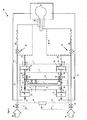
- FIG. 2 The inventive device 1 for mixture monitoring for gas mixtures according to the second embodiment is shown in FIG FIG. 2 shown together with a burner device 28.
- the second embodiment differs from the first embodiment in that on the base 3 facing side of the beam 6 at the beam ends 9, 10, a third and a fourth pressure / Wegwandler 40, 41 are arranged and connected to the beam ends 9, 10.
- the third pressure / displacement converter 40 has a connection opening 42, which is connected to a branch line 43 for supplying air or oxygen.
- the connection opening 42 opens into a pressure chamber 44, which is bounded by a membrane 45.
- the membrane 45 is connected via a linkage 46 with a arranged at the beam end 9 bearing 18.
- the fourth pressure / Wegwandler 41 has a connection opening 47 which is connected to a branch line 48 for supplying fuel gas.
- the connection opening 47 opens into a pressure chamber 49, which is delimited by a membrane 50.
- the membrane 50 is connected via a linkage 51 with a arranged on the beam end 10 bearing 24.
- the branch line 14 of the first pressure / displacement converter 11 and the branch line of the third pressure / Wegwandlers 43 are connected to a first line section 52.
- a flow resistance 53 is integrated into the first line section 52.
- the flow resistance 53 may have a variable flow resistance, such as a flow resistance. a valve, his.
- the branch line 20 of the second pressure / Wegwandlers 12 and the branch line 48 of the fourth pressure / Wegwandlers 41 are connected to a second line section 54.
- a flow resistance 55 is integrated into the second line section 54.
- the flow resistance 55 may be a variable flow resistance.
- the two opposing pressure / displacement transducers 11, 40 and 12, 41 transmit the pressure applied to the membranes 16, 45 and 22, 50, respectively, of the corresponding fluid to the rods 17, 46 and 23, 51, respectively Linkage 17, 46 and 23, 51 act on the corresponding beam end 9, 10 of the ratio pressure rocker 2 with a force. This force is proportional to the pressure difference decreasing at the flow resistances. In this way, the fluid flows or the volume flows of the two fluids are compared.
- the linkage 17 and 46 or 23 and 51 can also be designed in each case as a linkage.
- the linkages 17, 46, 23, 51 may have an axial bearing 57.
- the air or oxygen flows from the air / oxygen source 29 or the gas flows from the gas source 33 to the burner 32.
- the direction along which these currents flow is referred to as the flow direction 56.
- the first and second pressure / displacement transducers 11, 12 are connected to the branch line 14, 20 arranged upstream of the flow resistance 53, 54 in the flow direction 56.
- the third and fourth pressure / displacement transducers 40, 41 are connected to the branch line 43, 48 arranged downstream of the flow resistance 53, 54 in the flow direction 56.
- the arranged on the side facing away from the base 3 side pressure / Wegwandler 11, 12 also engage on the same side of the beam 6 and act on the beam 6 each with a force. With respect to the supports 4, 5 they each exert an opposite moment on the beam.
- the inventive device 1 for mixture monitoring for fluid mixtures according to the second embodiment is in a burner device 28 according to FIG. 2 used. Unless otherwise described, the burner apparatus corresponds to the burner apparatus according to the first embodiment.
- the first and second line sections are part of the feed lines 31, 35.
- the branch lines 14, 20, 43, 48 thus open into the respective feed line 31, 35.
- the method for fluid monitoring for fluid mixtures of two fluids by means of the monitoring device 1 according to the invention with reference to the in FIG. 2 illustrated burner device 28 explained. Unless otherwise described, the method corresponds to the method according to the first exemplary embodiment.
- the air or oxygen passes via the connection openings 13, 42 into the pressure chambers of the first and third pressure / displacement transducers 11, 40.
- the gas pressure applied in the pressure chambers 15, 44 exerts in each case a force on the membranes 16, 45 of the pressure / Wegwandler 11, 40 from.
- the corresponding fuel gas passes via the connection openings 19, 47 into the pressure chambers of the second and fourth pressure / displacement transducers 12, 49.
- the gas pressure applied in the pressure chambers 21, 49 exerts a respective force on the membranes 22, 50 of the pressure / Wegwandler 12, 49 from.
- the desired ratio of the resulting forces is set. If the resulting forces in the desired ratio within the allowable tolerance, then the beam 6 is in equilibrium and the fluid mixture can be supplied to the burner.
- variable flow resistances 53, 55 By means of the variable flow resistances 53, 55, the pressure difference between the respective pressure / displacement transducers 11, 12 connected upstream of the flow resistance 53, 55 and between the pressure / displacement transducers 40, 41 connected downstream of the flow resistance 53, 55 is adjustable. About the bar, the pressure difference ratio of the two flow resistances 53, 55 is compared. The desired ratio of the pressure difference or the volume flows is thus basically also on the flow resistance 53, 55 adjustable. This setting can also by a combination of the adjustment of the flow resistances 53, 55 and the displacement of the supports 4, 5 done.
- the gas mixture composition is subject during the firing process in the burner 32 system-related fluctuations or deviates from the setpoint range due to the failure or inaccuracies of the mixture control, which are within the equilibrium range or tolerance range set on the ratio pressure rocker 2.
- This tolerance range is set as in the first embodiment on the adjustable distance of the supports 4, 5.
- the bar tilts over the second or the first support 5, 4 in the direction of maximum lambda safety switch 7 or lambda minimum safety switch 8 and the corresponding bar end 9, 10 contacts one of the two safety switches 7, 8.
- a signal is given to the safety controller 26.
- the safety control device 26 outputs a closing signal to the two valves 30, 34 via the signal lines 36, 37 and the valves 30, 34 are immediately closed.
- the burner 32 is no longer supplied with gas and goes out or shuts off. In this way, for example, the occurrence of a blockage or a hole or the failure or deviations of Gemsichregelung the entire burner device 28 switched off safely and reliably by the monitoring device 1 immediately.
- the pressure / displacement transducers 11, 12, 40, 41 can also have different effective areas for the implementation of a pressure in a path or a force. In this way, at high fluid pressure ratios of the two mixture-forming fluids by a suitable choice of the size of the active surfaces or membranes 16, 22, 45, 50 of the pressure / Wegwandler 11, 12, 40, 41 improves the accuracy of the turn-off. In addition, a suitable choice of the size of the effective surfaces of the pressure / Wegwandler 11, 12, 40, 41 allows a more compact design of the device. At a fluid pressure ratio of e.g. 1:20 results in an equilibrium point on the bar of 1: 2 instead of 1:20 with a membrane ratio of 1:10.
- the device according to the invention is preferably used for mixture monitoring for gas mixtures of two gases. But it can also be used to control any fluid mixtures, including liquids and / or gases.
- the differential pressure across the burner 32 is measured.
- This embodiment corresponds to the in FIG. 2 shown embodiment.
- the pressure / Wegwandier 40, 41 are directly connected to a combustion or furnace chamber of the burner 32.
- the differential pressure between the supply line 31, 35 in the region upstream of the flow resistances 53, 55 and the combustion or furnace chamber of the burner 32 is measured.
- the pressure Weg- / converter 11, 12 are connected to the lines 31, 35 immediately before the burner (dashed lines shown). In this case, the pressure difference acts solely on the differential pressure through the flow resistance of the burner.
- the devices according to the invention offer a high level of safety in the case of changes in the flow resistance due to staining and a false gas mixture composition resulting from a blockage on the burner.
- the device according to the invention according to the second and third embodiments offers the possibility to connect a monitoring device at almost any points of a burner device.
- a monitoring device for example, there is the possibility of a central overall mixture monitoring of several Einzelrbenneranlagen a furnace.
- a plurality of burners can be monitored with one monitoring device.
- the pressure / displacement transducers are preferably at a point of constant pressure, e.g. behind the two pressure control stations (30, 34) of the two fluids or behind a mixing point of the two gases in the burner, e.g. at firing upstream of the burner and downstream behind the burner in the furnace, arranged.
- the differential pressure is detected via the burner. In this way, O-chamber pressure fluctuations are compensated for in firing.
- the burner device is usually operated with an approved automatic burner control system / system (not shown). This controls the starting process of the burner via various sequences, with safety times and the usual parameters. About the automatic burner is released for a controller (not shown), the Burner controls. The burner is then in the operating state.
- the device according to the invention can with a prescribed max. Fault tolerance time of, for example, 3 seconds (realizable eg via approved safety time relay) can be simply switched off via a monitor chain input (not shown) of the burner burner control unit.
- the safety control device outputs an acoustic warning signal instead of the closing signal or in addition to the closing signal.
- the pressure measurement of the two fluids can take place at any point of the burner device.
- the monitoring device according to the invention can typically be used in high power burner devices with a power of 500 kW to several megawatts.
- the monitoring device can be used as a second channel for an electronic mixture preparation, which usually has its own automatic shutdown.
- the monitoring device according to the invention is a cost-effective, reliable electromechanical solution with which simply the requirements of the standards can be met.
- the monitoring device according to the invention is also basically suitable alone intrinsically safe to monitor a burner or other mixing ratio.
Landscapes
- Engineering & Computer Science (AREA)
- Chemical & Material Sciences (AREA)
- Combustion & Propulsion (AREA)
- Mechanical Engineering (AREA)
- General Engineering & Computer Science (AREA)
- Regulation And Control Of Combustion (AREA)
- Measuring Fluid Pressure (AREA)
- Examining Or Testing Airtightness (AREA)
Applications Claiming Priority (1)
| Application Number | Priority Date | Filing Date | Title |
|---|---|---|---|
| DE102008015311A DE102008015311A1 (de) | 2008-03-20 | 2008-03-20 | Vorrichtung zur Gemischüberwachung für Gasgemische aus zwei Gasen |
Publications (3)
| Publication Number | Publication Date |
|---|---|
| EP2103873A2 true EP2103873A2 (fr) | 2009-09-23 |
| EP2103873A3 EP2103873A3 (fr) | 2011-05-11 |
| EP2103873B1 EP2103873B1 (fr) | 2014-10-01 |
Family
ID=40566412
Family Applications (1)
| Application Number | Title | Priority Date | Filing Date |
|---|---|---|---|
| EP09004041.1A Not-in-force EP2103873B1 (fr) | 2008-03-20 | 2009-03-20 | Dispositif pour contrôler un mélange de deux fluides |
Country Status (2)
| Country | Link |
|---|---|
| EP (1) | EP2103873B1 (fr) |
| DE (1) | DE102008015311A1 (fr) |
Cited By (1)
| Publication number | Priority date | Publication date | Assignee | Title |
|---|---|---|---|---|
| EP2940388B1 (fr) | 2014-05-02 | 2019-06-05 | Air Products And Chemicals, Inc. | Système de surveillance de brûleur à distance |
Citations (3)
| Publication number | Priority date | Publication date | Assignee | Title |
|---|---|---|---|---|
| EP1207340A2 (fr) | 2000-11-18 | 2002-05-22 | Buderus Heiztechnik GmbH | Procédé de réglage d'un brûleur |
| EP1239220A2 (fr) | 2001-03-08 | 2002-09-11 | Robert Bosch Gmbh | Appareil à combustion de gaz utlisé à des fins de chauffage |
| DE102007001904A1 (de) | 2006-01-19 | 2007-09-13 | Vaillant Gmbh | Verfahren zum Regeln des Brennstoff-Luft-Verhältnisses eines brennstoffbetriebenen Brenners |
Family Cites Families (3)
| Publication number | Priority date | Publication date | Assignee | Title |
|---|---|---|---|---|
| DE605873C (de) * | 1932-06-07 | 1934-11-19 | Karl Lampmann | Mischregler |
| US3058043A (en) * | 1958-09-04 | 1962-10-09 | Sperry Rand Corp | Electrical controller for fuel ratio control system |
| DE1108960B (de) * | 1958-10-04 | 1961-06-15 | Continental Elektro Ind Ag | Einrichtung zur Aussteuerung eines Druckes, insbesondere bei pneumatischen Reglern |
-
2008
- 2008-03-20 DE DE102008015311A patent/DE102008015311A1/de not_active Withdrawn
-
2009
- 2009-03-20 EP EP09004041.1A patent/EP2103873B1/fr not_active Not-in-force
Patent Citations (3)
| Publication number | Priority date | Publication date | Assignee | Title |
|---|---|---|---|---|
| EP1207340A2 (fr) | 2000-11-18 | 2002-05-22 | Buderus Heiztechnik GmbH | Procédé de réglage d'un brûleur |
| EP1239220A2 (fr) | 2001-03-08 | 2002-09-11 | Robert Bosch Gmbh | Appareil à combustion de gaz utlisé à des fins de chauffage |
| DE102007001904A1 (de) | 2006-01-19 | 2007-09-13 | Vaillant Gmbh | Verfahren zum Regeln des Brennstoff-Luft-Verhältnisses eines brennstoffbetriebenen Brenners |
Cited By (1)
| Publication number | Priority date | Publication date | Assignee | Title |
|---|---|---|---|---|
| EP2940388B1 (fr) | 2014-05-02 | 2019-06-05 | Air Products And Chemicals, Inc. | Système de surveillance de brûleur à distance |
Also Published As
| Publication number | Publication date |
|---|---|
| EP2103873B1 (fr) | 2014-10-01 |
| DE102008015311A1 (de) | 2009-09-24 |
| EP2103873A3 (fr) | 2011-05-11 |
Similar Documents
| Publication | Publication Date | Title |
|---|---|---|
| EP1621811A1 (fr) | Procédé de fonctionnement pour un dispositif de combustion | |
| WO1999063272A1 (fr) | Systeme de regulation pour bruleur a gaz | |
| EP0039932A2 (fr) | Dispositif pour régler la proportion des gaz pour appareils anesthésiques | |
| EP0030736A2 (fr) | Appareil de régulation de la quantité d'air de combustion pour un brûleur | |
| EP1331444B1 (fr) | Méthode de régulation d'un brûleur à gaz | |
| EP3683500B1 (fr) | Procédé de régulation d'un mélange gazeux à l'aide d'un capteur de gaz et d'un capteur de mélange gazeux | |
| EP0907052A2 (fr) | Dispositif de commande de rapport pneumatique | |
| DE2657854A1 (de) | Gasdruckregler | |
| EP2405198B1 (fr) | Procédé de calibration de régulation du rapport gaz combustible-air d'un brûleur à gaz combustible | |
| EP2103873B1 (fr) | Dispositif pour contrôler un mélange de deux fluides | |
| EP3870899B1 (fr) | Procédé de contrôle d'un capteur de mélange gazeux et d'un capteur d'ionisation dans un appareil de chauffage fonctionnant au gaz combustible | |
| DE102011005511B4 (de) | Verfahren zur Steuerung eines Gasventil-Systems für einen Gasbrenner und Gaskochgerät mit einem Gasbrenner mit einem solchen Gasventil-System | |
| DE964997C (de) | Regelungsanlage mit einem Umschalter zur wahlweisen selbsttaetigen Regelung oder Handregelung mittels desselben Stellmotors | |
| DE10159033B4 (de) | Regelungsverfahren für Heizungsgeräte | |
| EP0977021B1 (fr) | Méthode pour la mesure du débit d'un fluide dans un canal d'écoulement | |
| EP3988841A1 (fr) | Procédé et dispositif pour empêcher le retour de flamme dans un dispositif brûleur pour un mélange préalablement mélangé de combustible et d'air | |
| EP3734159A1 (fr) | Procédé de vérification d'un capteur de mélange gazeux dans un appareil chauffant fonctionnant au gaz combustible | |
| DE2018187B2 (de) | Verfahren und einrichtung zur vermeidung des flammenrueckschlags in einem brennersystem | |
| DE102020126992A1 (de) | Verfahren und Vorrichtung zum sicheren Betrieb eines mit hohem Wasserstoffanteil betriebenen Brenners | |
| EP2976571B1 (fr) | Robinet de régulation de gaz | |
| DE2752021C3 (de) | Einrichtung zum Regeln der Größe des Luftüberschusses in den Verbrennungsgasen einer Verbrennungsanlage | |
| DE2827771C2 (de) | Regeleinrichtung für Gas- oder Ölfeuerungen mit einer Verbundverstellung | |
| DE3633660C2 (fr) | ||
| EP2908055B1 (fr) | Vanne de gaz dotée d'un système de contrôle d'air comprimé intégré | |
| EP3759391B1 (fr) | Dispositif d'affichage d'état d'un brûleur à gaz |
Legal Events
| Date | Code | Title | Description |
|---|---|---|---|
| PUAI | Public reference made under article 153(3) epc to a published international application that has entered the european phase |
Free format text: ORIGINAL CODE: 0009012 |
|
| AK | Designated contracting states |
Kind code of ref document: A2 Designated state(s): AT BE BG CH CY CZ DE DK EE ES FI FR GB GR HR HU IE IS IT LI LT LU LV MC MK MT NL NO PL PT RO SE SI SK TR |
|
| AX | Request for extension of the european patent |
Extension state: AL BA RS |
|
| REG | Reference to a national code |
Ref country code: DE Ref legal event code: R079 Ref document number: 502009010021 Country of ref document: DE Free format text: PREVIOUS MAIN CLASS: F23D0014720000 Ipc: G05D0011130000 |
|
| PUAL | Search report despatched |
Free format text: ORIGINAL CODE: 0009013 |
|
| AK | Designated contracting states |
Kind code of ref document: A3 Designated state(s): AT BE BG CH CY CZ DE DK EE ES FI FR GB GR HR HU IE IS IT LI LT LU LV MC MK MT NL NO PL PT RO SE SI SK TR |
|
| AX | Request for extension of the european patent |
Extension state: AL BA RS |
|
| RIC1 | Information provided on ipc code assigned before grant |
Ipc: F23D 14/72 20060101ALI20110407BHEP Ipc: F23N 5/24 20060101ALI20110407BHEP Ipc: F23N 5/18 20060101ALI20110407BHEP Ipc: G05D 11/13 20060101AFI20110407BHEP |
|
| RAP1 | Party data changed (applicant data changed or rights of an application transferred) |
Owner name: NEISCHWANDER, MICHAEL Owner name: FRYEN, HEIKO |
|
| AKY | No designation fees paid | ||
| REG | Reference to a national code |
Ref country code: DE Ref legal event code: R108 |
|
| REG | Reference to a national code |
Ref country code: DE Ref legal event code: R108 Ref document number: 502009010021 Country of ref document: DE Effective date: 20120118 |
|
| 17P | Request for examination filed |
Effective date: 20120207 |
|
| RBV | Designated contracting states (corrected) |
Designated state(s): DE FR GB |
|
| RIC1 | Information provided on ipc code assigned before grant |
Ipc: F23N 5/24 20060101ALI20140220BHEP Ipc: F23N 5/18 20060101ALI20140220BHEP Ipc: G05D 11/13 20060101AFI20140220BHEP Ipc: F23D 14/72 20060101ALI20140220BHEP |
|
| GRAP | Despatch of communication of intention to grant a patent |
Free format text: ORIGINAL CODE: EPIDOSNIGR1 |
|
| INTG | Intention to grant announced |
Effective date: 20140514 |
|
| GRAS | Grant fee paid |
Free format text: ORIGINAL CODE: EPIDOSNIGR3 |
|
| GRAA | (expected) grant |
Free format text: ORIGINAL CODE: 0009210 |
|
| AK | Designated contracting states |
Kind code of ref document: B1 Designated state(s): DE FR GB |
|
| REG | Reference to a national code |
Ref country code: GB Ref legal event code: FG4D Free format text: NOT ENGLISH |
|
| REG | Reference to a national code |
Ref country code: DE Ref legal event code: R096 Ref document number: 502009010021 Country of ref document: DE Effective date: 20141113 |
|
| REG | Reference to a national code |
Ref country code: DE Ref legal event code: R097 Ref document number: 502009010021 Country of ref document: DE |
|
| PLBE | No opposition filed within time limit |
Free format text: ORIGINAL CODE: 0009261 |
|
| STAA | Information on the status of an ep patent application or granted ep patent |
Free format text: STATUS: NO OPPOSITION FILED WITHIN TIME LIMIT |
|
| 26N | No opposition filed |
Effective date: 20150702 |
|
| REG | Reference to a national code |
Ref country code: FR Ref legal event code: PLFP Year of fee payment: 8 |
|
| REG | Reference to a national code |
Ref country code: FR Ref legal event code: PLFP Year of fee payment: 9 |
|
| REG | Reference to a national code |
Ref country code: FR Ref legal event code: PLFP Year of fee payment: 10 |
|
| PGFP | Annual fee paid to national office [announced via postgrant information from national office to epo] |
Ref country code: FR Payment date: 20210302 Year of fee payment: 13 |
|
| PGFP | Annual fee paid to national office [announced via postgrant information from national office to epo] |
Ref country code: GB Payment date: 20210302 Year of fee payment: 13 |
|
| GBPC | Gb: european patent ceased through non-payment of renewal fee |
Effective date: 20220320 |
|
| PG25 | Lapsed in a contracting state [announced via postgrant information from national office to epo] |
Ref country code: GB Free format text: LAPSE BECAUSE OF NON-PAYMENT OF DUE FEES Effective date: 20220320 Ref country code: FR Free format text: LAPSE BECAUSE OF NON-PAYMENT OF DUE FEES Effective date: 20220331 |
|
| PGFP | Annual fee paid to national office [announced via postgrant information from national office to epo] |
Ref country code: DE Payment date: 20240319 Year of fee payment: 16 |