EP3734159A1 - Procédé de vérification d'un capteur de mélange gazeux dans un appareil chauffant fonctionnant au gaz combustible - Google Patents
Procédé de vérification d'un capteur de mélange gazeux dans un appareil chauffant fonctionnant au gaz combustible Download PDFInfo
- Publication number
- EP3734159A1 EP3734159A1 EP20171903.6A EP20171903A EP3734159A1 EP 3734159 A1 EP3734159 A1 EP 3734159A1 EP 20171903 A EP20171903 A EP 20171903A EP 3734159 A1 EP3734159 A1 EP 3734159A1
- Authority
- EP
- European Patent Office
- Prior art keywords
- gas
- sensor
- gas mixture
- mixture
- signal
- Prior art date
- Legal status (The legal status is an assumption and is not a legal conclusion. Google has not performed a legal analysis and makes no representation as to the accuracy of the status listed.)
- Withdrawn
Links
- 239000007789 gas Substances 0.000 title claims abstract description 176
- 239000000203 mixture Substances 0.000 title claims abstract description 141
- 238000000034 method Methods 0.000 title claims abstract description 45
- 239000000567 combustion gas Substances 0.000 title 1
- 239000002737 fuel gas Substances 0.000 claims abstract description 72
- 239000000463 material Substances 0.000 claims abstract description 13
- 238000010438 heat treatment Methods 0.000 claims abstract description 7
- 230000001419 dependent effect Effects 0.000 claims abstract description 4
- 239000000446 fuel Substances 0.000 claims description 5
- 230000001105 regulatory effect Effects 0.000 claims description 3
- VNWKTOKETHGBQD-UHFFFAOYSA-N methane Chemical compound C VNWKTOKETHGBQD-UHFFFAOYSA-N 0.000 description 10
- 230000033228 biological regulation Effects 0.000 description 6
- 238000002485 combustion reaction Methods 0.000 description 5
- 239000003345 natural gas Substances 0.000 description 5
- 238000011161 development Methods 0.000 description 3
- 230000018109 developmental process Effects 0.000 description 3
- 238000010586 diagram Methods 0.000 description 3
- 239000007788 liquid Substances 0.000 description 3
- 238000005259 measurement Methods 0.000 description 3
- GVGLGOZIDCSQPN-PVHGPHFFSA-N Heroin Chemical compound O([C@H]1[C@H](C=C[C@H]23)OC(C)=O)C4=C5[C@@]12CCN(C)[C@@H]3CC5=CC=C4OC(C)=O GVGLGOZIDCSQPN-PVHGPHFFSA-N 0.000 description 2
- ATUOYWHBWRKTHZ-UHFFFAOYSA-N Propane Chemical compound CCC ATUOYWHBWRKTHZ-UHFFFAOYSA-N 0.000 description 2
- 230000003247 decreasing effect Effects 0.000 description 2
- 230000006978 adaptation Effects 0.000 description 1
- 239000001273 butane Substances 0.000 description 1
- 230000007423 decrease Effects 0.000 description 1
- 238000003745 diagnosis Methods 0.000 description 1
- 238000009434 installation Methods 0.000 description 1
- 238000012423 maintenance Methods 0.000 description 1
- 238000012544 monitoring process Methods 0.000 description 1
- IJDNQMDRQITEOD-UHFFFAOYSA-N n-butane Chemical compound CCCC IJDNQMDRQITEOD-UHFFFAOYSA-N 0.000 description 1
- OFBQJSOFQDEBGM-UHFFFAOYSA-N n-pentane Natural products CCCCC OFBQJSOFQDEBGM-UHFFFAOYSA-N 0.000 description 1
- 230000000704 physical effect Effects 0.000 description 1
- 239000001294 propane Substances 0.000 description 1
- 239000000523 sample Substances 0.000 description 1
- 238000012360 testing method Methods 0.000 description 1
- 238000002604 ultrasonography Methods 0.000 description 1
Images


Classifications
-
- F—MECHANICAL ENGINEERING; LIGHTING; HEATING; WEAPONS; BLASTING
- F23—COMBUSTION APPARATUS; COMBUSTION PROCESSES
- F23N—REGULATING OR CONTROLLING COMBUSTION
- F23N1/00—Regulating fuel supply
- F23N1/02—Regulating fuel supply conjointly with air supply
- F23N1/022—Regulating fuel supply conjointly with air supply using electronic means
-
- F—MECHANICAL ENGINEERING; LIGHTING; HEATING; WEAPONS; BLASTING
- F23—COMBUSTION APPARATUS; COMBUSTION PROCESSES
- F23N—REGULATING OR CONTROLLING COMBUSTION
- F23N5/00—Systems for controlling combustion
- F23N5/02—Systems for controlling combustion using devices responsive to thermal changes or to thermal expansion of a medium
- F23N5/12—Systems for controlling combustion using devices responsive to thermal changes or to thermal expansion of a medium using ionisation-sensitive elements, i.e. flame rods
- F23N5/123—Systems for controlling combustion using devices responsive to thermal changes or to thermal expansion of a medium using ionisation-sensitive elements, i.e. flame rods using electronic means
-
- F—MECHANICAL ENGINEERING; LIGHTING; HEATING; WEAPONS; BLASTING
- F23—COMBUSTION APPARATUS; COMBUSTION PROCESSES
- F23N—REGULATING OR CONTROLLING COMBUSTION
- F23N5/00—Systems for controlling combustion
- F23N5/24—Preventing development of abnormal or undesired conditions, i.e. safety arrangements
- F23N5/242—Preventing development of abnormal or undesired conditions, i.e. safety arrangements using electronic means
-
- F—MECHANICAL ENGINEERING; LIGHTING; HEATING; WEAPONS; BLASTING
- F23—COMBUSTION APPARATUS; COMBUSTION PROCESSES
- F23N—REGULATING OR CONTROLLING COMBUSTION
- F23N2225/00—Measuring
- F23N2225/26—Measuring humidity
- F23N2225/30—Measuring humidity measuring lambda
-
- F—MECHANICAL ENGINEERING; LIGHTING; HEATING; WEAPONS; BLASTING
- F23—COMBUSTION APPARATUS; COMBUSTION PROCESSES
- F23N—REGULATING OR CONTROLLING COMBUSTION
- F23N2227/00—Ignition or checking
- F23N2227/12—Burner simulation or checking
- F23N2227/16—Checking components, e.g. electronic
-
- F—MECHANICAL ENGINEERING; LIGHTING; HEATING; WEAPONS; BLASTING
- F23—COMBUSTION APPARATUS; COMBUSTION PROCESSES
- F23N—REGULATING OR CONTROLLING COMBUSTION
- F23N2233/00—Ventilators
- F23N2233/06—Ventilators at the air intake
- F23N2233/08—Ventilators at the air intake with variable speed
-
- F—MECHANICAL ENGINEERING; LIGHTING; HEATING; WEAPONS; BLASTING
- F23—COMBUSTION APPARATUS; COMBUSTION PROCESSES
- F23N—REGULATING OR CONTROLLING COMBUSTION
- F23N2239/00—Fuels
- F23N2239/04—Gaseous fuels
Definitions
- the invention relates to a method for checking a gas mixture sensor with regard to its fault-free function by checking the plausibility of its measured values in a heating device operated by fuel gas.
- the state of the art is also, for example, combustion control according to the so-called SCOT method, in which the amount of air supplied to the burner of the heater is controlled according to the burner output.
- a flame signal measurement is carried out by means of an ionization sensor and the gas-air mixture is regulated to a target ionization measurement value stored in a characteristic curve.
- the disadvantage of the SCOT process is that the flame signal and the control system drop sharply at low burner outputs making it unreliable.
- the applicant also has a method for regulating a gas mixture formed from a gas and a fuel gas in a fuel gas-operated heater, in which the gas mixture is generated by providing and mixing a gas quantity via a first actuator and a fuel gas quantity via a second actuator.
- a microthermal gas mixture sensor which detects at least one material property of the gas mixture, is subjected to the gas mixture and continuously transmits a sensor signal that is dependent on the respective gas mixture to a control unit.
- the control unit compares the detected sensor signal with a setpoint value of the sensor signal and controls at least one of the first and second actuators in the event of a discrepancy between the detected sensor signal and the setpoint value of the sensor signal.
- the gas mixture is adjusted by increasing or decreasing the amount of gas and / or increasing or decreasing the amount of fuel gas until the target value of the sensor signal is reached.
- the material property of the gas mixture detected by the microthermal gas mixture sensor is preferably the thermal conductivity, the thermal conductivity or the speed of sound of the gas mixture. However, several of these material properties can also be recorded, so that a more precise assignment of the majority of the properties to the gas mixture is possible.
- the microthermal gas mixture sensor is designed as a gas mass sensor, which records both the gas mixture mass fed to the burner of the heater and other material physical properties.
- calorimetric microsensors known from the prior art are used for this purpose, which in addition to the thermal conductivity detect the thermal conductivity of the gas mixture.
- Another possibility consists in at least one gas mass sensor based on the functional principle of ultrasound measurement for determining the gas mixture mass and the specific sound velocity that is present as a function of the gas mixture.
- the setpoint value of the sensor signal is also adapted by the control device as a function of a composition of the gas or of the fuel gas. If the composition of the fuel gas changes (e.g. from propane to butane), the measured properties of the gas mixture change. In addition, different compositions of fuel gas also require different amounts of air for optimal combustion. A new mixing ratio between gas and fuel gas is therefore also required.
- the composition of the fuel gas changes (e.g. from propane to butane)
- the measured properties of the gas mixture change.
- different compositions of fuel gas also require different amounts of air for optimal combustion. A new mixing ratio between gas and fuel gas is therefore also required.
- control unit changes the first actuator for the gas quantity or the second actuator for the fuel gas quantity until the desired result is achieved.
- the original setpoint is replaced by the new measured sensor signal for further mixture control.
- the calibration process takes place by means of an ionization current control of a flame signal from a burner of the heater until a target ionization value is reached.
- a stoichiometric combustion of the burner of the heater is first set.
- the flame signal of the burner of the heater and thus a corresponding ionization current are recorded via an ionization probe.
- the ionization current is at a maximum.
- a nominal ionization value is calculated from this value of the ionization current with a percentage determined by laboratory technology and stored as a future nominal ionization current value which must be achieved with the desired combustion. Then only the amount of gas is reduced by a predetermined factor in order to operate the burner with the desired gas mixture at the predetermined ionization target value.
- the at least one material property of the gas mixture is measured by means of the gas mixture sensor and stored in the control device as the new target value of the sensor signal.
- the new setpoint is used for further control and replaces the previous setpoint.
- the gas is preferably air, and the fuel gas is preferably liquid gas or natural gas.
- the object of the present invention is to check the measured sensor value of the gas mixture sensor for plausibility, i.e. be checked with regard to its error-free function in order to be able to detect errors in the control process.
- a method for checking a gas mixture sensor with regard to its error-free function in a fuel gas-operated heater is proposed, a gas mixture being generated by providing and mixing a gas quantity via a first actuator and a fuel gas quantity via a second actuator.
- the gas mixture sensor is positioned in the gas mixture to detect a material property of the gas mixture and continuously transmits a sensor signal that is dependent on the respective gas mixture to a control unit.
- the control unit Based on a target value of the sensor signal of the gas mixture sensor, temporarily changes the amount of fuel gas in a predefined manipulated variable of the second actuator for a target gas mixture for checking the gas mixture sensor, so that a mixture ratio of the gas mixture changes.
- the amount of gas is then increased via the first actuator until the target value of the sensor signal of the gas mixture sensor is reached again.
- the amount of fuel gas is preferably kept constant.
- the values of the amount of fuel gas and the amount of gas that are subsequently set are recorded, from which the mixing ratio of the changed gas mixture is calculated and compared with the target gas mixture. By comparing the values and the size of their deviation, it is possible to conclude that the gas mixture sensor is functioning correctly or with errors. If the calculated result of the mixture ratio of the changed gas mixture deviates too much from that of the target gas mixture, there is an error in the gas mixture sensor in front.
- the absolute size of the deviation of the sensor signal of the gas mixture sensor can be detected and compared with laboratory-determined or precalculated variables in order to determine a degree of deviation of the signal from the target value. This makes it possible to define a tolerance range for the sensor signal, which is considered normal for regular operation.
- the limit of the permitted deviation is user-definable and may not, for example, exceed a deviation of 10%.
- the amount of gas is preferably provided via a fan.
- the value of the gas amount that is established after the increase in the amount of gas is determined in a first embodiment variant from a speed of the fan via a speed-gas amount characteristic curve stored in the control device.
- the value of the gas amount that is set after the increase in the amount of gas is measured using a gas sensor.
- the method is further characterized in that a flame signal is detected via the ionization sensor on a burner of the heater, the ionization signal is determined therefrom and transmitted to the control device.
- a corresponding ionization signal of the ionization sensor is assigned to the respective sensor signal of the gas mixture sensor in order to be able to compare the two signal values and thus additionally be able to check plausibility. If the deviation is too great, a fault diagnosis can be shown on a display of the heater, for example.
- the calibration process is carried out, which represents a type of recalibration for the control method of the gas mixture.
- This recalibration is preferably carried out within the control range of the ionization sensor in order to be able to compare the values between the gas mixture sensor and the ionization sensor. If the absolute size of the deviation of the sensor signal from the gas mixture sensor then continues to be outside the tolerance range, the control unit can carry out a safety shutdown of the heater or continue the regulation process of the gas mixture exclusively via the ionization sensor. The gas mixture sensor is then not taken into account for the control process until the next maintenance of the heater.
- a further development of the method is characterized in that a gas sensor and / or a fuel gas sensor is additionally used to detect at least one of the material properties of the gas and / or the fuel gas.
- the property of the gas is measured via the gas sensor and the property of the fuel gas is measured via the fuel gas sensor, whereby it is advantageous that the respective end points of the sensor characteristic of the sensor signal of the gas mixture sensor are determined from the signals from the gas sensor and fuel gas sensor.
- the first end point is determined by pure fuel gas, the second end point by pure gas, in particular air. In this way, when the gas (air) or the fuel gas changes, the characteristic curve of the gas mixture sensor and therefore the setpoint values of the sensor signals can be adjusted without recalibration being necessary.
- the gas mixture sensor, the gas sensor and / or the fuel gas sensor are provided redundantly.
- Each of the redundantly provided gas mixture sensors, gas sensors and / or fuel gas sensors advantageously supplies its own signal to the control device, which is checked for plausibility and therefore the sensors are checked for their correct function.
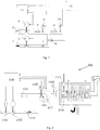
- FIG. 1 shows a basic structure for carrying out the mixture control.
- air is always assumed to be the gas, even if other gases can theoretically also be used.
- control unit 11 controls the actuator 4 for supplying a controllable amount of air 2 and the actuator 3 for supplying a controllable amount of fuel gas 1 in their respective open positions in order to generate the gas mixture 9 in a certain fuel gas-air mixture ratio.
- the gas mixture sensor 10 is positioned in the region of the gas mixture 9 and the gas mixture 9 is applied to it.
- the fuel gas sensor 6 is positioned in the fuel gas path 5 and the gas sensor 8 is positioned in the gas path 7, and these sensors also supply signals to the control unit 11.
- the control device 11 and the regulation are monitored via a process monitoring unit 12.
- FIG 2 shows a specific embodiment of a fuel gas operated heater 200 with a gas safety valve 101, a gas control valve 102 as an actuator for the amount of fuel gas 103, a mixing fan 107 for Sucking in air 104 and mixing it with the fuel gas 103 to generate the gas mixture 105.
- the amount of air can be adjusted via the speed of the mixing fan 107; it therefore represents the actuator for the air supply.
- the heater 200 includes the microthermal gas mixture sensor 106, a second gas mixture sensor 108 being shown as an alternative installation position in the blow-out area of the mixing fan 107. In principle, however, no second gas mixture sensor is required.
- the mixing fan 107 conveys the gas mixture 105 to the burner 109, on which the ionization sensor 111 with the ionization electrode is installed in order to monitor the burner flame.
- the signal lines to and from the control device 100, which processes the regulation of the gas mixture 105, are shown via arrows.
- Figure 3 is in a diagram 30 a simplified linear relationship used for the control between the sensor signal 31 detected by the gas mixture sensor 10 with pure air 2 (reference number 34 corresponds to 100% air) and the sensor signal 32 with pure fuel gas 1 (reference number 36 corresponds to 100% fuel gas) shown.
- the sensor signal 33 lies in between.
- the quantities of air 2 and fuel gas 1 are adjusted via the respective actuators 3 and / or 4 until the mixture properties of the desired mixture ratio required by the process are detected by the gas mixture sensor 10.
- Figure 3 shows a linear course of the characteristic curve of the sensor signal, but non-linear characteristic curves are also possible which, for example, enable regulation of the corresponding positions of the actuators 3, 4 via value tables.
- the sensor signal decreases the more fuel gas 1 is supplied.
- the sensor signal is shown as a function of the thermal conductivity as a material property of the gas mixture 9, the fuel gas for example Liquid gas and the thermal conductivity of liquid gas is lower than that of air.
- the fuel gas 1 is natural gas, the thermal conductivity of which is higher than that of air.
- diagram 40 according to Figure 4 a simplified linear relationship used for the regulation between the sensor signal 41 detected by the gas mixture sensor 10 for pure air 2 (reference number 44 corresponds to 100% air) and the sensor signal 42 for pure fuel gas 1 (reference number 46 corresponds to 100% fuel gas / natural gas).
- the sensor signal 43 lies in between, but is close to the sensor signal 41 of pure fuel gas 1.
- the control unit 11 uses the signal change of the gas mixture sensor 10 at the Increasing the amount of fuel gas determines the direction of action of the control and is used as the basis for further mixture control.
- Figure 5 shows a diagram 20 for calibration by means of ionization current regulation with a characteristic curve of the ionization signal (lo signal) detected by the ionization electrode in the burner flame versus the fuel gas / air ratio ⁇ . Since the basic structure according to Figure 1 shows no ionization electrode, the heater 200 according to FIG Figure 2 referenced.
- the control unit 100 controls the amount of air 104 to a predetermined value, measures the ionization signal at the ionization electrode of the ionization sensor 111 on the burner 109 and increases the amount of fuel gas 103 until the ionization signal changes from the originally present ionization value 21 at a Fuel gas / air ratio 24 has risen to the maximum 22.
- the ionization setpoint value 23 is calculated with a laboratory-technically determined percentage and stored as a future ionization current setpoint value, which the desired fuel gas / air ratio 25 must be achieved with, for example, a higher air excess.
- a corresponding sensor signal of the gas mixture sensor 108 is stored for each value of the ionization signal.
- the characteristic curve 80 of the increase in the amount of fuel gas when carrying out the method according to the invention is shown.
- the abscissa determines the opening position P of the actuator 3 of the fuel gas, the ordinate the flow rate F of fuel gas, which forms the fuel gas component of the gas mixture.
- the increase takes place in steps 82 from points a, b, c, d, e, the fuel gas quantity F increasing in each case essentially constantly over a fixed amount 81.
- the change in the amount of fuel gas causes a shift in the mixture composition in% of fuel gas and air with an unchanged amount of air and consequently a changing sensor signal S of the gas mixture sensor 108, as in FIG Figure 7 shown.
- the two end points 61, 65 of the sensor characteristic 60 determine the mixture composition in% at reference number 68, pure air or, at reference number 66, pure fuel gas.
- the amount of fuel on the test mixture composition 67 identified in FIG Figure 7 with reference numeral 67, the sensor signal S changing by a signal difference 72 in error-free operation.
- the amount of air is increased by increasing the speed of the mixing fan 107 until the setpoint value of the sensor signal of the gas mixture sensor 108 is reached again.
- the then existing values of the amount of fuel gas and the amount of air are measured via the gas sensors 104 and the fuel gas sensors 103 and the mixing ratio of the newly set gas mixture is calculated from this.
- the calculated mixture ratio of the newly set gas mixture is compared with the target gas mixture and the deviation is determined, which must not exceed a predetermined tolerance limit, since otherwise the gas mixture sensor will not function properly and, for example, the described recalibration and renewed Plausibility check of the error-free function of the gas mixture sensor is carried out.
Applications Claiming Priority (1)
| Application Number | Priority Date | Filing Date | Title |
|---|---|---|---|
| DE102019110977.9A DE102019110977A1 (de) | 2019-04-29 | 2019-04-29 | Verfahren zur Überprüfung eines Gasgemischsensors bei einem brenngasbetriebenen Heizgerät |
Publications (1)
| Publication Number | Publication Date |
|---|---|
| EP3734159A1 true EP3734159A1 (fr) | 2020-11-04 |
Family
ID=70476061
Family Applications (1)
| Application Number | Title | Priority Date | Filing Date |
|---|---|---|---|
| EP20171903.6A Withdrawn EP3734159A1 (fr) | 2019-04-29 | 2020-04-28 | Procédé de vérification d'un capteur de mélange gazeux dans un appareil chauffant fonctionnant au gaz combustible |
Country Status (2)
| Country | Link |
|---|---|
| EP (1) | EP3734159A1 (fr) |
| DE (1) | DE102019110977A1 (fr) |
Cited By (1)
| Publication number | Priority date | Publication date | Assignee | Title |
|---|---|---|---|---|
| EP4012260A1 (fr) * | 2020-12-07 | 2022-06-15 | ebm-papst Landshut GmbH | Procédé de régulation d'un procédé de combustion d'une chaudière à gaz et chaudière à gaz |
Citations (3)
| Publication number | Priority date | Publication date | Assignee | Title |
|---|---|---|---|---|
| WO2006000366A1 (fr) | 2004-06-23 | 2006-01-05 | Ebm-Papst Landshut Gmbh | Procede pour reguler et commander un dispositif de combustion, et dispositif de combustion |
| DE202019100263U1 (de) * | 2019-01-17 | 2019-02-04 | Ebm-Papst Landshut Gmbh | Heizgerät mit Regelung eines Gasgemisches unter Nutzung eines Gassensors, eines Brenngassensors und eines Gasgemischsensors |
| DE202019100261U1 (de) * | 2019-01-17 | 2019-02-04 | Ebm-Papst Landshut Gmbh | Heizgerät mit Regelung eines Gasgemisches |
Family Cites Families (3)
| Publication number | Priority date | Publication date | Assignee | Title |
|---|---|---|---|---|
| ATE189301T1 (de) * | 1995-10-25 | 2000-02-15 | Stiebel Eltron Gmbh & Co Kg | Verfahren und schaltung zur regelung eines gasbrenners |
| DE10113468A1 (de) * | 2000-09-05 | 2002-03-14 | Siemens Building Tech Ag | Regeleinrichtung für einen Luftzahlgeregelten Brenner |
| AT510075B1 (de) * | 2010-07-08 | 2012-05-15 | Vaillant Group Austria Gmbh | Verfahren zur kalibrierung einer einrichtung zum regeln des brenngas-luft-verhältnisses eines brenngasbetriebenen brenners |
-
2019
- 2019-04-29 DE DE102019110977.9A patent/DE102019110977A1/de active Pending
-
2020
- 2020-04-28 EP EP20171903.6A patent/EP3734159A1/fr not_active Withdrawn
Patent Citations (3)
| Publication number | Priority date | Publication date | Assignee | Title |
|---|---|---|---|---|
| WO2006000366A1 (fr) | 2004-06-23 | 2006-01-05 | Ebm-Papst Landshut Gmbh | Procede pour reguler et commander un dispositif de combustion, et dispositif de combustion |
| DE202019100263U1 (de) * | 2019-01-17 | 2019-02-04 | Ebm-Papst Landshut Gmbh | Heizgerät mit Regelung eines Gasgemisches unter Nutzung eines Gassensors, eines Brenngassensors und eines Gasgemischsensors |
| DE202019100261U1 (de) * | 2019-01-17 | 2019-02-04 | Ebm-Papst Landshut Gmbh | Heizgerät mit Regelung eines Gasgemisches |
Cited By (1)
| Publication number | Priority date | Publication date | Assignee | Title |
|---|---|---|---|---|
| EP4012260A1 (fr) * | 2020-12-07 | 2022-06-15 | ebm-papst Landshut GmbH | Procédé de régulation d'un procédé de combustion d'une chaudière à gaz et chaudière à gaz |
Also Published As
| Publication number | Publication date |
|---|---|
| DE102019110977A1 (de) | 2020-10-29 |
Similar Documents
| Publication | Publication Date | Title |
|---|---|---|
| EP3683500B1 (fr) | Procédé de régulation d'un mélange gazeux à l'aide d'un capteur de gaz et d'un capteur de mélange gazeux | |
| EP2466204B1 (fr) | Dispositif de réglage pour une installation de brûleur | |
| DE3638410C2 (fr) | ||
| EP3824366B1 (fr) | Dispositif de réglage d'un mélange gazeux au moyen d'un capteur de gaz, d'un capteur de gaz combustible et d'un capteur de mélange gazeux | |
| DE202019100263U1 (de) | Heizgerät mit Regelung eines Gasgemisches unter Nutzung eines Gassensors, eines Brenngassensors und eines Gasgemischsensors | |
| EP3870899B1 (fr) | Procédé de contrôle d'un capteur de mélange gazeux et d'un capteur d'ionisation dans un appareil de chauffage fonctionnant au gaz combustible | |
| AT505244B1 (de) | Verfahren zur überprüfung des ionisationselektrodensignals bei brennern | |
| EP3596391A1 (fr) | Procédé de régulation d'un appareil de chauffage fonctionnant avec du gaz combustible | |
| DE2509344C3 (de) | Verfahren und Anordnung zur automatischen Regelung einer Kessel-Turbinen-Einheit | |
| EP3325882B1 (fr) | Dispositif de régulation pour un brûleur de gaz | |
| DE202019100261U1 (de) | Heizgerät mit Regelung eines Gasgemisches | |
| DE102017222437A1 (de) | Heizgerätkomponente und Verfahren zur Einstellung eines Brennstoffvolumenstroms | |
| EP3734159A1 (fr) | Procédé de vérification d'un capteur de mélange gazeux dans un appareil chauffant fonctionnant au gaz combustible | |
| EP2405198A1 (fr) | Procédé de calibration de régulation du rapport gaz combustible-air d'un brûleur à gaz combustible | |
| EP3746705A1 (fr) | Procédé de réglage d'un mélange gazeux au moyen d'un capteur de mélange gazeux | |
| DE19854824C1 (de) | Verfahren und Schaltung zur Regelung eines Gasbrenners | |
| EP3746706B1 (fr) | Procédé pour la régulation d'un rapport de mélange de gaz combustible et d'air pour un appareil de chauffage | |
| EP3751200B1 (fr) | Procédé de régulation d'un appareil chauffant à gaz combustible | |
| DE202019100264U1 (de) | Heizgerät mit Regelung eines Gasgemisches unter Nutzung eines Gassensors und eines Gasgemischsensors | |
| DE10220773A1 (de) | Verfahren und Einrichtung zur Regelung eines Verbrennungsprozesses, insbesondere eines Brenners | |
| DE10056064B4 (de) | Verfahren zum Regeln eines Gasbrenners | |
| DE2753520C2 (de) | Vorrichtung zum Optimieren des Luft/Brennstoffverhältnisses von mit gasförmigen oder flüssigen Brennstoffen betriebenen Feuerungsanlagen | |
| DE3203675C2 (de) | Verfahren zur Regelung des Luftüberschusses an Feuerungen sowie Einrichtung zum Regeln des Luftüberschusses | |
| DE102020104084A1 (de) | Verfahren zur Überwachung und Regelung eines Prozesses einer Gastherme und Gastherme | |
| DE19908885A1 (de) | Verfahren zum Betrieb eines mit Brenngasen wechselnder Zusammensetzungen versorgten Energieumsetzers |
Legal Events
| Date | Code | Title | Description |
|---|---|---|---|
| PUAI | Public reference made under article 153(3) epc to a published international application that has entered the european phase |
Free format text: ORIGINAL CODE: 0009012 |
|
| STAA | Information on the status of an ep patent application or granted ep patent |
Free format text: STATUS: THE APPLICATION HAS BEEN PUBLISHED |
|
| AK | Designated contracting states |
Kind code of ref document: A1 Designated state(s): AL AT BE BG CH CY CZ DE DK EE ES FI FR GB GR HR HU IE IS IT LI LT LU LV MC MK MT NL NO PL PT RO RS SE SI SK SM TR |
|
| AX | Request for extension of the european patent |
Extension state: BA ME |
|
| STAA | Information on the status of an ep patent application or granted ep patent |
Free format text: STATUS: REQUEST FOR EXAMINATION WAS MADE |
|
| 17P | Request for examination filed |
Effective date: 20210329 |
|
| RBV | Designated contracting states (corrected) |
Designated state(s): AL AT BE BG CH CY CZ DE DK EE ES FI FR GB GR HR HU IE IS IT LI LT LU LV MC MK MT NL NO PL PT RO RS SE SI SK SM TR |
|
| RIN1 | Information on inventor provided before grant (corrected) |
Inventor name: HERMANN, JENS Inventor name: WALD, STEPHAN Inventor name: HENRICH, HARTMUT |
|
| STAA | Information on the status of an ep patent application or granted ep patent |
Free format text: STATUS: EXAMINATION IS IN PROGRESS |
|
| 17Q | First examination report despatched |
Effective date: 20230316 |
|
| STAA | Information on the status of an ep patent application or granted ep patent |
Free format text: STATUS: THE APPLICATION IS DEEMED TO BE WITHDRAWN |
|
| 18D | Application deemed to be withdrawn |
Effective date: 20230727 |