EP2102467B1 - Entlüftung für einen flüssigkeitskreislauf - Google Patents
Entlüftung für einen flüssigkeitskreislauf Download PDFInfo
- Publication number
- EP2102467B1 EP2102467B1 EP08707863.0A EP08707863A EP2102467B1 EP 2102467 B1 EP2102467 B1 EP 2102467B1 EP 08707863 A EP08707863 A EP 08707863A EP 2102467 B1 EP2102467 B1 EP 2102467B1
- Authority
- EP
- European Patent Office
- Prior art keywords
- circuit
- venting
- section
- connection region
- circuit section
- Prior art date
- Legal status (The legal status is an assumption and is not a legal conclusion. Google has not performed a legal analysis and makes no representation as to the accuracy of the status listed.)
- Not-in-force
Links
- 239000007788 liquid Substances 0.000 title description 46
- 238000013022 venting Methods 0.000 claims description 143
- 238000001816 cooling Methods 0.000 claims description 54
- 239000012530 fluid Substances 0.000 claims description 48
- 230000000694 effects Effects 0.000 claims description 39
- 230000003068 static effect Effects 0.000 claims description 12
- 238000013461 design Methods 0.000 claims description 8
- 238000000034 method Methods 0.000 claims description 7
- 230000001154 acute effect Effects 0.000 claims description 2
- 238000011144 upstream manufacturing Methods 0.000 claims 2
- 230000003247 decreasing effect Effects 0.000 claims 1
- 239000000126 substance Substances 0.000 description 6
- 238000000926 separation method Methods 0.000 description 5
- 230000002123 temporal effect Effects 0.000 description 4
- 238000009423 ventilation Methods 0.000 description 4
- 239000007789 gas Substances 0.000 description 3
- 230000006378 damage Effects 0.000 description 2
- 238000005086 pumping Methods 0.000 description 2
- 230000007704 transition Effects 0.000 description 2
- 230000001174 ascending effect Effects 0.000 description 1
- 238000010276 construction Methods 0.000 description 1
- 238000007796 conventional method Methods 0.000 description 1
- 230000006735 deficit Effects 0.000 description 1
- 230000001419 dependent effect Effects 0.000 description 1
- 238000000605 extraction Methods 0.000 description 1
- 238000009434 installation Methods 0.000 description 1
- 238000012423 maintenance Methods 0.000 description 1
- 230000008439 repair process Effects 0.000 description 1
- 230000000630 rising effect Effects 0.000 description 1
- 230000009528 severe injury Effects 0.000 description 1
- 239000002918 waste heat Substances 0.000 description 1
Images
Classifications
-
- F—MECHANICAL ENGINEERING; LIGHTING; HEATING; WEAPONS; BLASTING
- F01—MACHINES OR ENGINES IN GENERAL; ENGINE PLANTS IN GENERAL; STEAM ENGINES
- F01P—COOLING OF MACHINES OR ENGINES IN GENERAL; COOLING OF INTERNAL-COMBUSTION ENGINES
- F01P11/00—Component parts, details, or accessories not provided for in, or of interest apart from, groups F01P1/00 - F01P9/00
- F01P11/02—Liquid-coolant filling, overflow, venting, or draining devices
- F01P11/028—Deaeration devices
-
- F—MECHANICAL ENGINEERING; LIGHTING; HEATING; WEAPONS; BLASTING
- F01—MACHINES OR ENGINES IN GENERAL; ENGINE PLANTS IN GENERAL; STEAM ENGINES
- F01P—COOLING OF MACHINES OR ENGINES IN GENERAL; COOLING OF INTERNAL-COMBUSTION ENGINES
- F01P2025/00—Measuring
- F01P2025/04—Pressure
Definitions
- the present invention relates to an arrangement for a liquid circuit with ventilation, in particular for a cooling circuit.
- the arrangement in this case comprises a first circuit section of the fluid circuit, a second circuit section of the fluid circuit and a venting device for venting the first circuit section.
- the second circulation section is arranged in the flow direction after the first circulation section and before the venting.
- the venting device opens to vent the first circuit section in a first connection region in the first circuit section and in a second connection region in the second circuit section.
- the invention relates to a corresponding fluid circuit, a vehicle with such a fluid circuit and a corresponding method for venting a fluid circuit.
- Liquid circuits such as cooling circuits for cooling components of a vehicle, must be vented continuously or at certain times.
- venting is to be understood as meaning the separation of any gaseous substances from the fluid circuit. The venting is necessary to ensure the proper functioning of the liquid circuit, ie to ensure a sufficient liquid flow and to prevent damage to the installed components, for example by cavitation. Cavitation effects, as a rule, lead to severe damage to the affected components, including total damage to these components. The consequences are very expensive repairs to the complete replacement of the affected components.
- a vent line for venting the component is therefore usually mounted at least at the highest point of the highest liquid-flow component. From this point, the vent line runs steadily increasing, a limited line length possibly also horizontally, to a higher air separator, such as a corresponding container in which air and / or other gaseous substances are separated from the liquid.
- the object of the present invention is therefore to provide an arrangement for a fluid circuit of the type mentioned above which does not have the abovementioned disadvantages or at least to a significantly lesser extent and in particular with simple and cost-effective manufacturability and reliable function of the fluid circuit allows reliable venting of the fluid circuit.
- the present invention solves this problem starting from an arrangement according to the preamble of claim 1 by the features stated in the characterizing part of claim 1. It continues to solve this task on the basis of a procedure according to the preamble of claim 19 by the features stated in the characterizing part of claim 19.
- the present invention is based on the technical teaching that, with simple and cost-effective manufacturability and reliable operation of the fluid circuit, reliable venting of the fluid circuit is possible if the first circuit section to be vented is activated by a suction effect in the venting device extending between the first circuit section and the second circuit section is at least partially vented into the second cycle section inside.
- the present invention therefore relates to an arrangement for a vented fluid circuit, in particular a cooling circuit comprising a first circuit section, a second circuit section and a venting device for venting the first circuit section.
- the second circulation section is arranged in the flow direction after the first circulation section and before the venting.
- the venting device for venting the first circuit section opens into the first circuit section in a first connection region and into the second cycle section in a second connection region.
- the second circuit section and / or the venting device is designed and / or arranged in the second connection region in such a way that a suction effect in the venting device that is sufficient for at least partially venting the first circuit section arises in the venting device.
- the venting device may be formed as an active device and comprise, for example, a corresponding pumping device, which achieves the suction effect required for at least partial venting of the first cycle section.
- the venting device is designed as a passive device, so that a corresponding at least partial venting of the first cycle section sufficient suction effect is achieved by appropriate design or arrangement of the second circuit section or the venting device alone by the pressure conditions in the flow in the liquid circuit.
- the at least partial venting of the first cycle section can be done at certain predetermined times.
- the fluid circuit is operated only in the event of predeterminable temporal and / or non-temporal events (for example when a predeterminable state of the fluid circuit is detected and / or at specific times) in a venting mode in which a suction effect sufficient for venting is produced.
- a venting mode in which a suction effect sufficient for venting is produced.
- the generation of the suction effect and thus the venting takes place continuously.
- the second circuit section and / or the venting device is designed and / or arranged in the second connection region in such a way that the suction effect in the venting device that is sufficient for at least partially venting the first circuit section takes place during normal operation of the fluid circuit.
- the suction effect in the venting device that is sufficient for at least partially venting the first circuit section takes place during normal operation of the fluid circuit.
- a venting operation of the liquid circuit in which controlled by a corresponding control device for a certain time an increased flow velocity is generated in the circuit, from which only a sufficient for the vent suction effect results.
- the pressure gradient required in the venting device for generating the suction effect can be achieved in any suitable manner.
- the pressure gradient is simply generated via a corresponding difference in the static pressure between the first connection region and the second connection region.
- the second circuit section and / or the venting device is designed and / or arranged in the second connection region such that the static pressure in the second connection region is lower than in the first connection region.
- a pump device for generating the liquid flow in the liquid circuit.
- the first connection region is then arranged between the pump outlet of the pump device and the second connection region. Due to the flow losses between the first connection area and the second one Connection area occur, can already be achieved in the meantime a corresponding pressure difference for the first connection area and the second connection area.
- the design and / or the length of the flow path between the first connection region and the second connection region is therefore preferably selected so that the pressure loss in the liquid circuit over the flow path is sufficient to produce the suction effect in the ventilation device that is sufficient for at least partially venting the first cycle section.
- This can be achieved solely by a corresponding flow resistance of the lines used on this flow path or for other purposes existing components, such as check valves, etc. If appropriate, however, it is also possible to install a separate throttle device which is present only for this purpose in the flow path.
- the second circuit section or the venting device can basically have any desired configuration.
- the second circuit section or the venting device can be arranged in the region of a component to be cooled and thereby have a complex-shaped geometry.
- the second circuit section and / or the venting device in the region of the second connection region has a tubular cross section, which can be achieved hereby a particularly simple design.
- the second circuit section prefferably has a larger diameter in the second connection region than the venting device.
- the diameter of the second circuit section is significantly larger than the diameter of the venting device, so that a relatively small disturbance is introduced into the liquid flow of the liquid circuit by the venting device.
- the venting device has an outlet opening in the second connection region and the outlet opening of the venting device is arranged in the region of the second circulation section in which the highest flow velocities occur in the flow of the liquid circulation , In this area with the highest flow velocities, the lowest static pressures are present in the flow, so that the highest suction effect can advantageously be achieved here.
- the venting device is arranged and designed so that the construction of a suction effect counteracting dynamic pressure in the venting device is avoided.
- the venting device therefore preferably has an outlet opening in the second connection region which is delimited by at least one wall of the venting device.
- the at least one wall is arranged in the flow of the liquid circuit in such a way that the outlet opening lies in the flow shadow of the wall. This can be prevented that the liquid from the liquid circuit penetrates into the venting device and builds up by the then occurring deceleration of the flow counteracting the suction suction back pressure.
- the wall of the venting device is tubular, wherein it has a longitudinal axis.
- the longitudinal axis of the tubular wall is inclined at most at an acute angle to the main flow direction of the flow in the second cycle section, so that the outlet opening can be easily arranged in the flow shadow of the wall.
- the longitudinal axis of the wall is substantially parallel to the main flow direction, so that the structure of one of the suction effect counteract the back pressure is reliably avoided.
- the second connection region is arranged in the region of a reduction of the free flow cross section of the second cycle section. This can be achieved in a particularly simple manner a significant reduction of the static pressure in the second connection region and thus a high suction effect (Venturi effect).
- the reduction of the free flow area may be achieved in any suitable manner.
- a constriction of the flow cross section may be provided.
- the reduction of the free flow cross-section is at least partially formed by a projecting into the second circuit section portion of the venting device.
- the section of the venting device projecting into the second circuit section is widened at its free end, in order to achieve in a simple manner a strong reduction of the free flow cross section and thus a high suction effect.
- the invention can be applied to any course of the venting device.
- it can also be used in a ventilation direction constantly increasing course of the venting device, since in this case the vent is further improved.
- the invention can be used to particular advantage in the case of an at least partially falling course of the venting device in the venting direction, since it also opens up the possibility of reliable venting here.
- the venting device has at least one venting section, the highest point of which lies in the normal operation of the fluid circuit below the first connection area.
- the invention can therefore also be used particularly advantageously if the second connection region lies below the first connection region in normal operation of the fluid circuit.
- a second venting device in particular a separating vessel, is provided as venting of the liquid circuit.
- the second venting device is arranged in the normal operation of the fluid circuit at least at the level of the second circuit section, in particular above the second circuit section. This can be achieved in a simple manner a reliable venting of the fluid circuit.
- the present invention further relates to a fluid circuit, in particular a cooling circuit, with an inventive arrangement.
- the invention can be used in any liquid circuits for any applications. Particularly advantageous it can be used because of the usually limited space conditions in conjunction with vehicles.
- a vehicle in particular a rail vehicle, with a fluid circuit according to the invention.
- the liquid circuit is designed as a cooling circuit of a component of the vehicle, in particular an engine of the vehicle.
- the present invention relates to a method for venting a fluid circuit, in particular a cooling circuit, wherein the fluid circuit comprises a first circuit section, a second circuit section, a first venting device for venting the first circuit section and a second venting device, the second circuit section in the flow direction after the first circuit section and is arranged in front of the second venting device and the liquid circuit is vented via the second venting device.
- the first circuit section is vented at least partially into the second circuit section via a suction effect in the first venting device.
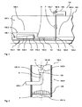
- the Figures 1 and 2 show schematic representations of a vehicle according to the invention in the form of a rail vehicle 101.
- the rail vehicle 101 comprises a car body 102 which is supported in the region of its two ends on two trolleys 103.1 and 103.2.
- the vehicle body 102 has a passenger compartment 102.1 with a bottom 102.2, wherein a high-floor area 102.3 and a low-floor area 102.4 are formed.
- a motor 104 is located below the floor.
- the engine 104 is cooled by a liquid circuit 105 serving as a cooling circuit.
- the cooling circuit 105 includes a pump 105. 1, which generates a liquid flow with a flow direction F in the cooling circuit 105.
- the cooling circuit 105 has a first circuit section 105. 2 which runs inside the motor 104.
- the cooling circuit is led to a roof cooling system 106, in which the heated by the waste heat of the engine 104 liquid is cooled in the cooling circuit again.
- the lines of the cooling circuit 105 must be guided a certain distance below the bottom 102.2 in the low-floor area 102.4, before they are guided in the side wall of the car body 102 upwards in the roof area of the car body 102.
- When filling the cooling circuit 105 and in its operation collect at the highest point of the first circuit section 105.2 air and other gases. In order to ensure the proper functioning of the cooling circuit 105, a venting of the cooling circuit 105 at this highest point is required.
- this highest point of the first circuit section 105.2 is formed as a first connection region 105.3, in which a first venting device in the form of a first venting line 105.4 is connected.
- the first vent line 105.4 is laid underground and extends from the first connection area 105.3 to a second circuit section 105.5 of the cooling circuit 105, which is arranged in the low-floor area 102.4.
- the first vent line 105.4 is connected to the second circuit section 105.5 in a second connection area 105.6, which in FIG. 2 is shown in more detail.
- the second connection region 105.6 lies in the region of the cooling circuit 105, starting from which the cooling circuit 105 is continuously ascending upwards to the roof cooling system 106.
- a vent in the form of a second venting device with a second vent line 105.7 and a separating vessel 105.8 is connected.
- the second vent line 105.7 leads to the separation vessel 105.8, in which the separation of air and other gases from the liquid of the cooling circuit 105 and thus the venting of the cooling circuit 105 takes place.
- the first connection area 105.3 of the first ventilation line 105.4 lies above the second connection area 105.6 during normal operation of the vehicle when the route is horizontal. This has the consequence that the first vent line 105.4 in the venting direction E over a certain section at the transition from the high-floor area 102.3 to the low-floor area 102.4 sloping, so that sets no venting effect alone due to the lower density of the discharged gaseous substances.
- a suction effect is generated in the first vent line 105.4, which conveys gaseous substances accumulating in the first connection region 105.3 through the first vent line 105.4 to the second connection region 105.6.
- the pressure difference .DELTA.P is chosen to be sufficiently large in order to achieve reliable venting of the first circulation section 105.2 during normal operation of the cooling circuit 105.
- the suction effect is set so high that preferably a substantially complete venting of the first circulation section 105.2 is achieved. However, it is not necessary to achieve a complete venting of the first circulation section 105.2. Rather, it is sufficient that a venting of the first cycle section is achieved, which is sufficient to avoid an impairment of the function of the cooling circuit 105. Optionally, therefore, a certain residual amount of gaseous substances remain in the first connection region.
- the pressure difference .DELTA.P is achieved in the present example on the one hand by the fact that the first connection region 105.3 in the flow direction F is significantly closer to the pump 105.1 than the second connection region 105.6, and therefore there is a flow path between the first connection region 105.3 and the second connection region 105.6.
- the length of the flow path between the first connection region 105.3 and the second connection region 105.6 and the design of the cooling circuit 105 in the region of this flow path are chosen such that the resulting on this flow path flow losses (for example at throttle points and / or by the flow resistance of the lines used and / or by the internal friction in the liquid) already sets a certain pressure difference, which is sufficient to produce a suction effect in the first vent line 105.4. If appropriate, the height difference between the first connection region 105.3 and the second connection region 105.6 is also taken into account here.
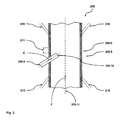
- FIG. 2 it can be seen is in the present example for generating the suction effect in the first vent line 105.4 in addition to the effect achieved in the second connection region via the flow loss on the flow path between the first connection region 105.3 and the second connection region 105.6 105.6 a reduction of the free flow cross-section of the liquid of the cooling circuit 105 is provided.
- This reduction of the free flow cross section results in an increase of the dynamic pressure in the liquid and thus an additional reduction of the static pressure in the liquid.
- the reduction of the free flow cross-section is achieved in the present example, that the first vent line 105.4 opens into the tubular second circuit section 105.5, wherein the free end 105.9 of the first vent line 105 protrudes into the second circuit section 105.5.
- the vent line 105.4 has a diameter which corresponds approximately to a quarter of the diameter of the second circuit section 105.5. However, the free end 105.9 of the first vent line 105.4 is widened to about one third of the diameter of the second circuit section 105.5.
- vent line 105.4 thus represents an obstacle that reduces the free flow cross-section, with the consequences described above with regard to the lowering of the static pressure, wherein an acceptable disability of the flow in the cooling circuit 105 is achieved by the selected diameter ratios. It goes without saying that the widening of the vent line 105.4 is not absolutely necessary. Rather, the vent line can be formed in other variants of the invention as a simple tube with a constant diameter, as in FIG. 2 is indicated by the dashed contour 108.
- the free end 105.9 has an outlet opening 105.10, which is preferably arranged in the region of the second circuit section 105.5, in which the highest flow velocities and thus the lowest static pressure in the liquid of the cooling circuit 105 is present.
- the outlet opening 105.10 is therefore arranged in the region of the center axis 105.11 of the second circulation section 105.5, since there prevail in the highest flow velocities, such as the velocity profile 109 of the flow FIG. 2 can be seen.
- vent line 105.4 is arranged so that its longitudinal axis 105.12 in the region of the free end 105.9 substantially parallel to the main flow direction F of
- Liquid runs in the present example thus coincides with the center axis 105.11 of the second circuit section 105.5.
- the surface normal A of the outlet opening 105.10 pointing in the direction of venting E points in the direction of the main flow direction F.
- the outlet opening 105.10 thus lies with respect to the liquid flow in the second circulation section 105.5 in the flow shadow of the wall of the first vent line 105.4, which defines the free end 105.9 and thus the outlet opening 105.10 trains. This avoids that the liquid of the cooling circuit 105 flows into the first vent line 105.4 and builds there by the deceleration of the flow of the vent counteracting backpressure.
- the cooling circuit 105 is designed in the present example so that the pressure difference .DELTA.P is built in the normal operation of the cooling circuit 105 and is substantially continuously present.
- the pressure difference .DELTA.P is built only in a temporary venting operation, which is carried out upon occurrence of any predeterminable temporal or non-temporal conditions or events.
- the pump 105.1 in this venting operation controlled by a control device 105.13, promotes a correspondingly increased volume flow through the cooling circuit 105.
- FIG. 3 shows a detail of another embodiment of a cooling circuit 205, as in the rail vehicle 101 from FIG. 1 can be used.
- the cooling circuit 205 corresponds to the except in the FIG. 3 shown part of the cooling circuit 105 from FIG. 1 , so that reference is made to the above statements with regard to the further design of the cooling circuit 205, and here only the differences are discussed.
- the first vent line 205.4 extends in this example in the second connection portion 205.6 obliquely into the tubular second circuit portion 205.5 inside.
- the first vent line 205.4 ends approximately halfway between the wall of the second circuit section 205.5 and the center axis 205.11 of the tubular circuit section 205.5.
- the outlet opening 205.10 is again arranged in the region of the highest flow velocities in the liquid of the cooling circuit 205, although it represents only a relatively small flow impediment to the liquid in the cooling circuit 205. This may be advantageous in view of the required for the cooling circuit 205 flow rate of the pump of the cooling circuit.
- outlet opening 205.10 is also arranged in this example so that it lies with respect to the liquid flow in the cooling circuit 205 (with the flow direction F) in the flow shadow of the wall of the first vent line 205.4, so that the structure of the vent in the venting direction E counteracting backpressure is avoided.
- the second circuit section is formed in the second connection area in the manner of a Venturi tube with a constricted flow cross section, so that in the region of the outlet opening of the first vent line a drop in the static pressure is achieved.
- the first vent line does not protrude into the second circuit section, but ends in the area of the wall, as in FIG FIG. 3 is indicated by the dashed contour 211.
Landscapes
- Engineering & Computer Science (AREA)
- Chemical & Material Sciences (AREA)
- Combustion & Propulsion (AREA)
- Mechanical Engineering (AREA)
- General Engineering & Computer Science (AREA)
- Cooling, Air Intake And Gas Exhaust, And Fuel Tank Arrangements In Propulsion Units (AREA)
- Production Of Liquid Hydrocarbon Mixture For Refining Petroleum (AREA)
Priority Applications (1)
| Application Number | Priority Date | Filing Date | Title |
|---|---|---|---|
| PL08707863T PL2102467T3 (pl) | 2007-01-11 | 2008-01-11 | Układ odpowietrzania obiegu cieczy |
Applications Claiming Priority (2)
| Application Number | Priority Date | Filing Date | Title |
|---|---|---|---|
| DE102007002453A DE102007002453A1 (de) | 2007-01-11 | 2007-01-11 | Entlüftung für einen Flüssigkeitskreislauf |
| PCT/EP2008/050296 WO2008084099A2 (de) | 2007-01-11 | 2008-01-11 | Entlüftung für einen flüssigkeitskreislauf |
Publications (2)
| Publication Number | Publication Date |
|---|---|
| EP2102467A2 EP2102467A2 (de) | 2009-09-23 |
| EP2102467B1 true EP2102467B1 (de) | 2014-05-14 |
Family
ID=39509916
Family Applications (1)
| Application Number | Title | Priority Date | Filing Date |
|---|---|---|---|
| EP08707863.0A Not-in-force EP2102467B1 (de) | 2007-01-11 | 2008-01-11 | Entlüftung für einen flüssigkeitskreislauf |
Country Status (4)
| Country | Link |
|---|---|
| EP (1) | EP2102467B1 (pl) |
| DE (1) | DE102007002453A1 (pl) |
| PL (1) | PL2102467T3 (pl) |
| WO (1) | WO2008084099A2 (pl) |
Families Citing this family (2)
| Publication number | Priority date | Publication date | Assignee | Title |
|---|---|---|---|---|
| DE102012006518A1 (de) * | 2012-03-29 | 2013-03-07 | Audi Ag | Kühlmittelkreislauf eines Fahrzeugs |
| DE102017116600A1 (de) | 2017-07-24 | 2019-01-24 | Volkswagen Aktiengesellschaft | Kühlsystem und Kraftfahrzeug |
Family Cites Families (9)
| Publication number | Priority date | Publication date | Assignee | Title |
|---|---|---|---|---|
| GB1026720A (en) * | 1964-04-28 | 1966-04-20 | London Transp Board | Improvements in or relating to vehicle engine cooling systems |
| US3576181A (en) * | 1969-06-02 | 1971-04-27 | Cummins Engine Co Inc | Apparatus for deaerating an engine cooling system |
| FR2086768A5 (pl) * | 1970-04-08 | 1971-12-31 | Peugeot & Renault | |
| US4199332A (en) * | 1977-12-07 | 1980-04-22 | Caterpillar Tractor Co. | Deaerator device |
| EP0257111A1 (de) * | 1986-08-14 | 1988-03-02 | AURORA Konrad G. Schulz GmbH & Co | Wärmetauscher für den Kühlkreislauf von Brennkraftmaschinen |
| FR2714851B1 (fr) * | 1994-01-07 | 1997-08-14 | Dominique Mercier | Procédé de traitement des solutions aqueuses par désorbtion de tout ou partie des gaz dissous qu'elles contiennent. |
| FR2715715B1 (fr) * | 1994-01-28 | 1997-07-04 | Radiadores Ordonez | Améliorations introduites dans les circuits de dégazage des radiateurs. |
| FR2730272B1 (fr) * | 1995-02-07 | 1997-04-25 | Peugeot | Reservoir d'expansion et de degazage pour circuit de refroidissement d'un moteur a combustion interne |
| US6843209B2 (en) * | 2001-06-20 | 2005-01-18 | Honda Giken Kogyo Kabushiki Kaisha | Engine cooling water passage structure and gas/liquid separator for engine cooling system |
-
2007
- 2007-01-11 DE DE102007002453A patent/DE102007002453A1/de not_active Withdrawn
-
2008
- 2008-01-11 WO PCT/EP2008/050296 patent/WO2008084099A2/de not_active Ceased
- 2008-01-11 PL PL08707863T patent/PL2102467T3/pl unknown
- 2008-01-11 EP EP08707863.0A patent/EP2102467B1/de not_active Not-in-force
Also Published As
| Publication number | Publication date |
|---|---|
| DE102007002453A1 (de) | 2008-07-17 |
| WO2008084099A2 (de) | 2008-07-17 |
| EP2102467A2 (de) | 2009-09-23 |
| WO2008084099A3 (de) | 2009-03-26 |
| PL2102467T3 (pl) | 2014-10-31 |
Similar Documents
| Publication | Publication Date | Title |
|---|---|---|
| DE102007023641B4 (de) | Ölfiltervorrichtung | |
| DE102008058981A1 (de) | Vorrichtung zur Vermeidung von hohen Öltank-Drücken unter negativen g-Bedingungen | |
| EP2102467B1 (de) | Entlüftung für einen flüssigkeitskreislauf | |
| EP1847413B1 (de) | Kraftstoffversorgungssystem für ein Fahrzeug | |
| DE102016202302A1 (de) | Saugkanalsystem für eine Getriebepumpe | |
| EP2468560B1 (de) | Kraftstoffsystem | |
| EP3024708B1 (de) | Hauptbremszylinderanordnung einer kraftfahrzeugbremsanlage mit filterelement sowie fluidreservoir und einsatzelement hierfür | |
| EP2705268B1 (de) | Hydraulische strecke mit einer entlüftungseinrichtung | |
| DE102009001564A1 (de) | Drosselelement | |
| DE102010008656B4 (de) | Abscheidevorrichtung | |
| EP3382193B1 (de) | Kraftstofffilter zum filtern von kraftstoff in einem kraftfahrzeug und kraftfahrzeug mit einem solchen kraftstofffilter | |
| EP3180219A1 (de) | Druckversorgungseinrichtung mit luftaufbereitungsanlage | |
| DE102015211372A1 (de) | Adaptive Entlüftungsvorrichtung für ein hydraulisches System und ein hydraulisches System | |
| DE102005011026B4 (de) | Einrichtung zur Trennung eines Kraftstoff-/Luftgemischs und Abscheidung von Kraftstoff aus diesem Gemisch | |
| DE102015000707A1 (de) | Vorrichtung zur Entlüftung eines Kraftstofftanks | |
| DE102011005464B4 (de) | Vorrichtung zur Erzeugung eines Unterdrucks | |
| DE10027569B4 (de) | Kraftstofftank eines Kraftfahrzeuges mit Druckentlüftungsventilen | |
| DE102016201254A1 (de) | Entlüftungsvorrichtung | |
| DE202022100817U1 (de) | Entwässerungsvorrichtung zum Entwässern des Inneren eines Übergangs für ein Gelenkfahrzeug | |
| DE102016011393A1 (de) | Schraubenkompressor für ein Nutzfahrzeug | |
| DE102005059457A1 (de) | Standheizung sowie ein hierfür bestimmtes Saugrohr | |
| DE102005053816A1 (de) | Entlüftungssystem für einen Kraftstoffbehälter | |
| DE102024122025A1 (de) | Hydrodynamischer Retarder mit Arbeitsmediumtank | |
| DE102013015955A1 (de) | Verbindungssystem zum Verbinden von wenigstens zwei Bauelementen eines Kraftwagens | |
| DE102016116631A1 (de) | Ansaugvorrichtung für die Ansaugung einer Flüssigkeit aus einer Flüssigkeitswanne in einem Kraftfahrzeug |
Legal Events
| Date | Code | Title | Description |
|---|---|---|---|
| PUAI | Public reference made under article 153(3) epc to a published international application that has entered the european phase |
Free format text: ORIGINAL CODE: 0009012 |
|
| 17P | Request for examination filed |
Effective date: 20090708 |
|
| AK | Designated contracting states |
Kind code of ref document: A2 Designated state(s): AT BE BG CH CY CZ DE DK EE ES FI FR GB GR HR HU IE IS IT LI LT LU LV MC MT NL NO PL PT RO SE SI SK TR |
|
| RIN1 | Information on inventor provided before grant (corrected) |
Inventor name: WILLBRANDT, RALPH Inventor name: JAHN, STEFFEN Inventor name: TROMMESHAUSER, WOLFGANG |
|
| DAX | Request for extension of the european patent (deleted) | ||
| 17Q | First examination report despatched |
Effective date: 20100416 |
|
| GRAP | Despatch of communication of intention to grant a patent |
Free format text: ORIGINAL CODE: EPIDOSNIGR1 |
|
| GRAS | Grant fee paid |
Free format text: ORIGINAL CODE: EPIDOSNIGR3 |
|
| GRAP | Despatch of communication of intention to grant a patent |
Free format text: ORIGINAL CODE: EPIDOSNIGR1 |
|
| INTG | Intention to grant announced |
Effective date: 20131128 |
|
| GRAA | (expected) grant |
Free format text: ORIGINAL CODE: 0009210 |
|
| AK | Designated contracting states |
Kind code of ref document: B1 Designated state(s): AT BE BG CH CY CZ DE DK EE ES FI FR GB GR HR HU IE IS IT LI LT LU LV MC MT NL NO PL PT RO SE SI SK TR |
|
| REG | Reference to a national code |
Ref country code: GB Ref legal event code: FG4D Free format text: NOT ENGLISH |
|
| REG | Reference to a national code |
Ref country code: AT Ref legal event code: REF Ref document number: 668469 Country of ref document: AT Kind code of ref document: T Effective date: 20140615 |
|
| REG | Reference to a national code |
Ref country code: IE Ref legal event code: FG4D Free format text: LANGUAGE OF EP DOCUMENT: GERMAN |
|
| REG | Reference to a national code |
Ref country code: DE Ref legal event code: R096 Ref document number: 502008011763 Country of ref document: DE Effective date: 20140703 |
|
| REG | Reference to a national code |
Ref country code: CH Ref legal event code: NV Representative=s name: TROESCH SCHEIDEGGER WERNER AG, CH |
|
| REG | Reference to a national code |
Ref country code: NL Ref legal event code: T3 |
|
| REG | Reference to a national code |
Ref country code: LT Ref legal event code: MG4D |
|
| PG25 | Lapsed in a contracting state [announced via postgrant information from national office to epo] |
Ref country code: IS Free format text: LAPSE BECAUSE OF FAILURE TO SUBMIT A TRANSLATION OF THE DESCRIPTION OR TO PAY THE FEE WITHIN THE PRESCRIBED TIME-LIMIT Effective date: 20140914 Ref country code: CY Free format text: LAPSE BECAUSE OF FAILURE TO SUBMIT A TRANSLATION OF THE DESCRIPTION OR TO PAY THE FEE WITHIN THE PRESCRIBED TIME-LIMIT Effective date: 20140514 Ref country code: GR Free format text: LAPSE BECAUSE OF FAILURE TO SUBMIT A TRANSLATION OF THE DESCRIPTION OR TO PAY THE FEE WITHIN THE PRESCRIBED TIME-LIMIT Effective date: 20140815 Ref country code: LT Free format text: LAPSE BECAUSE OF FAILURE TO SUBMIT A TRANSLATION OF THE DESCRIPTION OR TO PAY THE FEE WITHIN THE PRESCRIBED TIME-LIMIT Effective date: 20140514 Ref country code: NO Free format text: LAPSE BECAUSE OF FAILURE TO SUBMIT A TRANSLATION OF THE DESCRIPTION OR TO PAY THE FEE WITHIN THE PRESCRIBED TIME-LIMIT Effective date: 20140814 Ref country code: FI Free format text: LAPSE BECAUSE OF FAILURE TO SUBMIT A TRANSLATION OF THE DESCRIPTION OR TO PAY THE FEE WITHIN THE PRESCRIBED TIME-LIMIT Effective date: 20140514 |
|
| REG | Reference to a national code |
Ref country code: PL Ref legal event code: T3 |
|
| PG25 | Lapsed in a contracting state [announced via postgrant information from national office to epo] |
Ref country code: LV Free format text: LAPSE BECAUSE OF FAILURE TO SUBMIT A TRANSLATION OF THE DESCRIPTION OR TO PAY THE FEE WITHIN THE PRESCRIBED TIME-LIMIT Effective date: 20140514 Ref country code: HR Free format text: LAPSE BECAUSE OF FAILURE TO SUBMIT A TRANSLATION OF THE DESCRIPTION OR TO PAY THE FEE WITHIN THE PRESCRIBED TIME-LIMIT Effective date: 20140514 Ref country code: SE Free format text: LAPSE BECAUSE OF FAILURE TO SUBMIT A TRANSLATION OF THE DESCRIPTION OR TO PAY THE FEE WITHIN THE PRESCRIBED TIME-LIMIT Effective date: 20140514 Ref country code: ES Free format text: LAPSE BECAUSE OF FAILURE TO SUBMIT A TRANSLATION OF THE DESCRIPTION OR TO PAY THE FEE WITHIN THE PRESCRIBED TIME-LIMIT Effective date: 20140514 |
|
| PG25 | Lapsed in a contracting state [announced via postgrant information from national office to epo] |
Ref country code: PT Free format text: LAPSE BECAUSE OF FAILURE TO SUBMIT A TRANSLATION OF THE DESCRIPTION OR TO PAY THE FEE WITHIN THE PRESCRIBED TIME-LIMIT Effective date: 20140915 |
|
| PG25 | Lapsed in a contracting state [announced via postgrant information from national office to epo] |
Ref country code: DK Free format text: LAPSE BECAUSE OF FAILURE TO SUBMIT A TRANSLATION OF THE DESCRIPTION OR TO PAY THE FEE WITHIN THE PRESCRIBED TIME-LIMIT Effective date: 20140514 Ref country code: RO Free format text: LAPSE BECAUSE OF FAILURE TO SUBMIT A TRANSLATION OF THE DESCRIPTION OR TO PAY THE FEE WITHIN THE PRESCRIBED TIME-LIMIT Effective date: 20140514 Ref country code: SK Free format text: LAPSE BECAUSE OF FAILURE TO SUBMIT A TRANSLATION OF THE DESCRIPTION OR TO PAY THE FEE WITHIN THE PRESCRIBED TIME-LIMIT Effective date: 20140514 Ref country code: CZ Free format text: LAPSE BECAUSE OF FAILURE TO SUBMIT A TRANSLATION OF THE DESCRIPTION OR TO PAY THE FEE WITHIN THE PRESCRIBED TIME-LIMIT Effective date: 20140514 Ref country code: EE Free format text: LAPSE BECAUSE OF FAILURE TO SUBMIT A TRANSLATION OF THE DESCRIPTION OR TO PAY THE FEE WITHIN THE PRESCRIBED TIME-LIMIT Effective date: 20140514 |
|
| REG | Reference to a national code |
Ref country code: DE Ref legal event code: R097 Ref document number: 502008011763 Country of ref document: DE |
|
| PLBE | No opposition filed within time limit |
Free format text: ORIGINAL CODE: 0009261 |
|
| STAA | Information on the status of an ep patent application or granted ep patent |
Free format text: STATUS: NO OPPOSITION FILED WITHIN TIME LIMIT |
|
| 26N | No opposition filed |
Effective date: 20150217 |
|
| REG | Reference to a national code |
Ref country code: DE Ref legal event code: R097 Ref document number: 502008011763 Country of ref document: DE Effective date: 20150217 |
|
| PG25 | Lapsed in a contracting state [announced via postgrant information from national office to epo] |
Ref country code: BE Free format text: LAPSE BECAUSE OF NON-PAYMENT OF DUE FEES Effective date: 20150131 |
|
| PG25 | Lapsed in a contracting state [announced via postgrant information from national office to epo] |
Ref country code: SI Free format text: LAPSE BECAUSE OF FAILURE TO SUBMIT A TRANSLATION OF THE DESCRIPTION OR TO PAY THE FEE WITHIN THE PRESCRIBED TIME-LIMIT Effective date: 20140514 |
|
| PG25 | Lapsed in a contracting state [announced via postgrant information from national office to epo] |
Ref country code: LU Free format text: LAPSE BECAUSE OF FAILURE TO SUBMIT A TRANSLATION OF THE DESCRIPTION OR TO PAY THE FEE WITHIN THE PRESCRIBED TIME-LIMIT Effective date: 20150111 |
|
| PG25 | Lapsed in a contracting state [announced via postgrant information from national office to epo] |
Ref country code: MC Free format text: LAPSE BECAUSE OF FAILURE TO SUBMIT A TRANSLATION OF THE DESCRIPTION OR TO PAY THE FEE WITHIN THE PRESCRIBED TIME-LIMIT Effective date: 20140514 |
|
| REG | Reference to a national code |
Ref country code: IE Ref legal event code: MM4A |
|
| REG | Reference to a national code |
Ref country code: FR Ref legal event code: PLFP Year of fee payment: 9 |
|
| PG25 | Lapsed in a contracting state [announced via postgrant information from national office to epo] |
Ref country code: IE Free format text: LAPSE BECAUSE OF NON-PAYMENT OF DUE FEES Effective date: 20150111 |
|
| PGFP | Annual fee paid to national office [announced via postgrant information from national office to epo] |
Ref country code: NL Payment date: 20160120 Year of fee payment: 9 |
|
| PGFP | Annual fee paid to national office [announced via postgrant information from national office to epo] |
Ref country code: IT Payment date: 20160127 Year of fee payment: 9 Ref country code: TR Payment date: 20160105 Year of fee payment: 9 |
|
| PGFP | Annual fee paid to national office [announced via postgrant information from national office to epo] |
Ref country code: PL Payment date: 20160107 Year of fee payment: 9 |
|
| PG25 | Lapsed in a contracting state [announced via postgrant information from national office to epo] |
Ref country code: MT Free format text: LAPSE BECAUSE OF FAILURE TO SUBMIT A TRANSLATION OF THE DESCRIPTION OR TO PAY THE FEE WITHIN THE PRESCRIBED TIME-LIMIT Effective date: 20140514 |
|
| REG | Reference to a national code |
Ref country code: FR Ref legal event code: PLFP Year of fee payment: 10 |
|
| PG25 | Lapsed in a contracting state [announced via postgrant information from national office to epo] |
Ref country code: HU Free format text: LAPSE BECAUSE OF FAILURE TO SUBMIT A TRANSLATION OF THE DESCRIPTION OR TO PAY THE FEE WITHIN THE PRESCRIBED TIME-LIMIT; INVALID AB INITIO Effective date: 20080111 Ref country code: BG Free format text: LAPSE BECAUSE OF FAILURE TO SUBMIT A TRANSLATION OF THE DESCRIPTION OR TO PAY THE FEE WITHIN THE PRESCRIBED TIME-LIMIT Effective date: 20140514 |
|
| REG | Reference to a national code |
Ref country code: NL Ref legal event code: MM Effective date: 20170201 |
|
| PG25 | Lapsed in a contracting state [announced via postgrant information from national office to epo] |
Ref country code: NL Free format text: LAPSE BECAUSE OF NON-PAYMENT OF DUE FEES Effective date: 20170201 |
|
| REG | Reference to a national code |
Ref country code: FR Ref legal event code: PLFP Year of fee payment: 11 |
|
| PG25 | Lapsed in a contracting state [announced via postgrant information from national office to epo] |
Ref country code: IT Free format text: LAPSE BECAUSE OF NON-PAYMENT OF DUE FEES Effective date: 20170111 |
|
| PG25 | Lapsed in a contracting state [announced via postgrant information from national office to epo] |
Ref country code: PL Free format text: LAPSE BECAUSE OF NON-PAYMENT OF DUE FEES Effective date: 20170111 |
|
| PGFP | Annual fee paid to national office [announced via postgrant information from national office to epo] |
Ref country code: FR Payment date: 20190124 Year of fee payment: 12 Ref country code: GB Payment date: 20190121 Year of fee payment: 12 Ref country code: CH Payment date: 20190123 Year of fee payment: 12 Ref country code: DE Payment date: 20190123 Year of fee payment: 12 |
|
| PGFP | Annual fee paid to national office [announced via postgrant information from national office to epo] |
Ref country code: AT Payment date: 20190122 Year of fee payment: 12 |
|
| REG | Reference to a national code |
Ref country code: DE Ref legal event code: R119 Ref document number: 502008011763 Country of ref document: DE |
|
| REG | Reference to a national code |
Ref country code: CH Ref legal event code: PL |
|
| REG | Reference to a national code |
Ref country code: AT Ref legal event code: MM01 Ref document number: 668469 Country of ref document: AT Kind code of ref document: T Effective date: 20200111 |
|
| GBPC | Gb: european patent ceased through non-payment of renewal fee |
Effective date: 20200111 |
|
| PG25 | Lapsed in a contracting state [announced via postgrant information from national office to epo] |
Ref country code: FR Free format text: LAPSE BECAUSE OF NON-PAYMENT OF DUE FEES Effective date: 20200131 Ref country code: DE Free format text: LAPSE BECAUSE OF NON-PAYMENT OF DUE FEES Effective date: 20200801 Ref country code: GB Free format text: LAPSE BECAUSE OF NON-PAYMENT OF DUE FEES Effective date: 20200111 |
|
| PG25 | Lapsed in a contracting state [announced via postgrant information from national office to epo] |
Ref country code: LI Free format text: LAPSE BECAUSE OF NON-PAYMENT OF DUE FEES Effective date: 20200131 Ref country code: CH Free format text: LAPSE BECAUSE OF NON-PAYMENT OF DUE FEES Effective date: 20200131 Ref country code: AT Free format text: LAPSE BECAUSE OF NON-PAYMENT OF DUE FEES Effective date: 20200111 |
|
| PG25 | Lapsed in a contracting state [announced via postgrant information from national office to epo] |
Ref country code: TR Free format text: LAPSE BECAUSE OF NON-PAYMENT OF DUE FEES Effective date: 20170111 |