EP2101005B1 - Dredging machine and method of dredging - Google Patents
Dredging machine and method of dredging Download PDFInfo
- Publication number
- EP2101005B1 EP2101005B1 EP09154545.9A EP09154545A EP2101005B1 EP 2101005 B1 EP2101005 B1 EP 2101005B1 EP 09154545 A EP09154545 A EP 09154545A EP 2101005 B1 EP2101005 B1 EP 2101005B1
- Authority
- EP
- European Patent Office
- Prior art keywords
- movable body
- gallery
- sediment
- machine
- mobile
- Prior art date
- Legal status (The legal status is an assumption and is not a legal conclusion. Google has not performed a legal analysis and makes no representation as to the accuracy of the status listed.)
- Not-in-force
Links
Images


Classifications
-
- E—FIXED CONSTRUCTIONS
- E03—WATER SUPPLY; SEWERAGE
- E03F—SEWERS; CESSPOOLS
- E03F9/00—Arrangements or fixed installations methods or devices for cleaning or clearing sewer pipes, e.g. by flushing
- E03F9/002—Cleaning sewer pipes by mechanical means
-
- E—FIXED CONSTRUCTIONS
- E03—WATER SUPPLY; SEWERAGE
- E03F—SEWERS; CESSPOOLS
- E03F7/00—Other installations or implements for operating sewer systems, e.g. for preventing or indicating stoppage; Emptying cesspools
- E03F7/10—Wheeled apparatus for emptying sewers or cesspools
Definitions
- the present invention relates to a machine for cleaning sediments or the like deposited on the bottom of a gallery, for example a sewer, and a method of cleaning said sediments.
- the machine object of the invention relates more particularly to a system that allows the cleaning of emissaries of a sewerage network carrying wastewater or the like. As time passed, materials settled at the bottom of the galleries that make up these sewers. The operator periodically entrusts to companies cleaning works of said galleries.
- the document FR 2,693,220 shows a cleaning machine formed of two mobiles (13) and (32) in which the cleaning must be interrupted during the emptying of a second mobile (32), to avoid the transfer of sediment beyond a first mobile ( 13). So the cleaning process is interrupted.
- a first object of the invention is to provide a machine for cleaning sediments or the like which make it possible to avoid the disadvantages mentioned above.
- the complete machine is constituted by a first mobile which will be called after cleaning device and who performs the cleansing operation itself and which is provided with buffer storage means or temporary sediment removed at the bottom of the gallery, it is possible that the machine has a second mobile called marinating machine that can autonomously receive periodically stored sediment or the like temporarily on the cleaning machine and transport them to the area of the gallery or sewer corresponding to the evacuation of the sediments. It is of course understood that while the mariner makes its round trips, the cleaning machine can work permanently through the presence of buffer or temporary storage means called first storage means.
- the first moving means are first motor means mounted on the first mobile or cleaning device.
- the second moving means are also second motor means mounted on the second mobile or marinating machine.
- the first transfer means comprise a loading screw arranged in line with the scraping means and / or a conveyor whose one end cooperates with the loading screw or the scraper device and the second end is disposed above first storage means.
- said first storage means are arranged at the rear of the first mobile.
- the second transfer means are mounted on said first mobile.
- a second object of the invention is to provide a sediment cleaning process including but not exclusively capable of being implemented using the machine defined above.
- the cleaning machine consists essentially of a cleaning machine 10 and a pickling machine 12.
- the cleaning machine is the first mobile and the pickling machine is the second mobile .
- the cleaning device 10 comprises a support frame 14 equipped with a front wheel set 16 and, in the particular example described, two pairs of rear wheels 18 and 20.
- a cleaning device 24 which is essentially constituted by a cleaning or scraping blade 26 better visible on the Figure 2A .
- the shape of the cutting portion of the cleaning blade 26 is shaped to the shape of the lower portion 28 of the wall 30 of the gallery or sewer 32 in which the cleaning machine must intervene.
- the cleaning device 24 may comprise a raised position standby and a low operating position.
- a cylinder 34 allows to move from one to the other of these positions.
- the cleaning device 24 is associated with a first means for transferring sediments and other debris recovered by the blade 26 which bears the general reference 36.
- the first transfer device 36 is constituted by a loading screw 38 arranged in connection with the cleaning blade 26.
- the loading screw 38 is preferably constituted by two end portions 38a and 38b each provided with a blade 37 and a central portion 38c without blades.
- the function of the loading screw 38 is firstly due to the presence of the blades 37 to cut the pieces of sediment torn from the bottom of the gallery and secondly to bring back to the center these pieces of cut sediment.
- a jack 35 moves the screw 38 from a raised position to a lowered working position.
- the first transfer means 36 also comprises a conveyor 40 which has a first end 40a facing the loading screw 38 and preferably secured to the scraper blade 26 and a second end 40b.
- both the loading screw 38 and the conveyor 40 are mounted on the frame 14 of the cleaning machine.
- the cleaning machine also has at its rear end 42 a buffer hopper 44 which is the first storage means. This portion which is secured to the rear wheel trains 18 and 20 is preferably articulated about a vertical axis 46 relative to the front part of the cleaning machine 10. This joint 46 allows to conform the cleaning machine 10
- the buffer hopper 44 preferably has an inclined bottom 48.
- the cleaning apparatus 10 also comprises second transfer means constituted by the conveyor 50.
- This conveyor 50 has a first part 50a which is arranged inside the hopper 44 near its bottom 48 and a second portion 50b external thereto. The end 50c of the conveyor 50 is disposed well beyond the rear end 44a of the hopper 44.
- the wheel trains 16, 18 and 20 are pivotally mounted about axes which are angled relative to the horizontal. This arrangement makes it possible to conform the displacement of the cleaning apparatus to the shape of the bottom 28 of the wall 30 of the gallery.
- the cleaning apparatus 10 of course also includes a cabin 52 for controlling the vehicle, motors not shown to drive the wheel trains, these engines being for example hydraulic.
- the frame 14 also carries means for supplying pressurized fluid to control the rotation of the loading screw 38, the cylinders 34 and 35 for modifying the position of the cleaning blade 26, and the screw 38, as well as the conveyors 40 and 50.
- the cleaning machine also comprises a second mobile which is constituted by the pickling machine 12 whose function is as it was said to allow the transfer of sediment between the cleaning machine 10 and an unloading area provided in the gallery.
- the pickling machine 12 consists essentially of a frame 52 equipped for example with four sets of wheels 54, 56, 58 and 60.
- These wheels of course also have rotation axes inclined relative to the horizontal to bear against the walls of the gallery. Preferably, these wheels bear against this wall in a position farther from the bottom of the gallery than the wheel trains 16 to 20 of the cleaning apparatus 10. In fact, this gives better running conditions for the wheel. marinating machine since the bottom of the gallery may present inequalities. It is understood that this arrangement is particularly interesting since if the cleaning machine 10 moves very slowly and only travels the distance corresponding to the gallery length to be cleaned, the pickling machine 12 is made to make a large number back and forth between the cleaning machine 10 and the unloading point.
- the pickling machine 12 is equipped with a storage bin 62 which is preferably removable relative to the frame 52 of the pickling machine 12.
- the pickling machine 12 is also equipped with a driving cabin 64 and driving motors of at least some of the wheel trains 54 to 60.
- These wheels may be either standard wheels or roller wheels of the type described in the French patent FR 2 808 491 in the name of the plaintiff.
- the speed of movement of the cleaning machine 10 during operation is of course very limited to obtain effective cleaning of the gallery. For example, it is worth 1 or 2m / min.
- the machine of marinating 12, to go back and forth can of course have a higher speed of travel, for example of the order of 15 km / h.
- the volume capacity of the hopper 44 of the cleaning machine 10 is defined suitably the volume capacity of the hopper 44 of the cleaning machine 10.
- This volume capacity must be at least equal to the amount of sediment extracted by the cleaning device 10 when the mariner 12 travels the return trip between the cleaning machine 10 and the point of unloading sediment when the cleaning machine 10 is itself at the maximum distance from the unloading point .
- the first storage means thus constitute a buffer zone for temporary retention of cleaning products which thus makes the two mobile machines autonomous. It is also of course that the capacity of the bucket 62 is adapted to that of the hopper 44.
- the sediments are detached by the cleaning blade 26, they are transferred to the storage hopper 44 using the loading screw 38 and the first conveyor 40.
- the marinating machine 12 which is disposed at the rear of the cleaning machine 10 is filled with the sediment via the second conveyor 50. This fills the removable bucket 62 of the pickling machine 12
- the conveyor 50 is stopped and the pickling machine 12 moves to the unloading point P corresponding to an access 64 in the gallery 32.
- lifting means 66 can extract the removable bucket 62 full of sediment or cuttings and replace it with an empty bucket 62 which is placed on the frame of the pickling machine 12. This one then returns to the machine of curag 10 and it follows the slow progress of the cleaning machine 10.
- the conveyor 40 continues to transfer sediments into the hopper 44.
- the total amount of sediment transferred into the bucket 62 may therefore be that which was in the hopper at the beginning of the increased transfer of the amount of sediment transferred into the hopper during this transfer operation.
- the pickling machine 12 when the cleaning machine 10 is far from the maximum distance to which it must intervene, with respect to the point of unloading, the journeys made by the pickling machine 12 are relatively small and, outside the periods of back and forth, the picking machine follows the cleaning machine. On the other hand, when the cleaning apparatus 10 is close to the maximum planned sewage treatment distance, the pickling machine 12 remains at the station with the cleaning machine only substantially for the time of carrying out the transfer of the sewage treatment equipment. sediment or excavation of the hopper 44 to the bucket 62 using the conveyor 50.
- the mobiles constituted by the cleaning machine 10 and the pickling machine 12 may not be self-propelled and be driven by external propulsion means.
- the cleaning machine 10 and the mariner 12 may be self-propelled but controlled automatically remotely.
- these second transfer means are mounted on the marinating machine.
- these second transfer means could consist, for example, of a suction line or a screw system for transferring sediments from the hopper 44 to the bucket 62.
- the pickling machine 12 can also be used to transport fuel for the cleaning machine 10, personnel, or different maintenance elements of the cleaning machine.
Description
La présente invention a pour objet une machine de curage des sédiments ou analogues déposés sur le fond d'une galerie, par exemple un égout, et un procédé de curage desdits sédiments.The present invention relates to a machine for cleaning sediments or the like deposited on the bottom of a gallery, for example a sewer, and a method of cleaning said sediments.
Le curage, c'est-à-dire l'enlèvement des sédiments ou autres matériaux indésirables qui se déposent sur le fond des égouts ou plus généralement de galeries, soulève un certain nombre de problèmes. La machine objet de l'invention concerne plus particulièrement un système qui permet d'effectuer le curage d'émissaires d'un réseau d'assainissement véhiculant des eaux usées ou analogues. Au fur et à mesure de l'écoulement du temps, des matériaux se sont sédimentés au fond des galeries constituant ces égouts. L'exploitant confie périodiquement à des entreprises des travaux de curage desdites galeries.Cleaning, that is to say the removal of sediments or other undesirable materials that settle on the bottom of the sewers or more generally galleries, raises a certain number of problems. The machine object of the invention relates more particularly to a system that allows the cleaning of emissaries of a sewerage network carrying wastewater or the like. As time passed, materials settled at the bottom of the galleries that make up these sewers. The operator periodically entrusts to companies cleaning works of said galleries.
Le curage de telles galeries se réalise actuellement le plus souvent selon la technique suivante :
- on réalise un barrage pour pouvoir mettre à sec la galerie à curer ; et
- on réalise le curage par une chargeuse thermique, par exemple du type minier, munie d'un godet équipé d'une lame de raclage du fond de la galerie. Une fois que le godet est rempli, la chargeuse doit faire des allers et retours entre le front de curage et un puits d'accès à la surface où le déchargement du godet peut être réalisé. Le godet de la chargeuse est vidé en remplissant une benne qui est remontée par une grue pour être évacuée. Une telle solution est décrite dans le brevet français
2 701 278
- a dam is made to dry the gallery to be cleaned; and
- the cleaning is carried out by a heat loader, for example of the mining type, provided with a bucket equipped with a scraping blade of the bottom of the gallery. Once the bucket is filled, the loader has to go back and forth between the cleaning front and a surface access well where the unloading of the bucket can be made. The bucket of the loader is emptied by filling a bucket which is raised by a crane to be evacuated. Such a solution is described in the French patent
2,701,278
L'inconvénient principal d'une telle machine de curage d'égouts est que, pendant la phase de roulage de l'engin de curage, le curage est interrompu. On comprend que plus la distance entre le front de curage et le puits d'évacuation des sédiments récupérés augmente, plus la productivité de la machine diminue.The main disadvantage of such a sewer cleaning machine is that during the running phase of the cleaning machine, cleaning is interrupted. It is understood that the greater the distance between the cleaning front and the evacuation well of the recovered sediments, the more the productivity of the machine decreases.
En outre, le type d'engin décrit dans l'état de la technique antérieure consiste le plus souvent dans une machine du type pelle mécanique à chenille classique et impose que l'on mette à sec la galerie qui doit être traitée. On comprend que l'obligation qu'a la machine de faire les allers et retours entre le front de curage et la zone de déchargement fait que de longues périodes se déroulent sans que la machine de curage ne soit opérationnelle. On a donc dans ce cas une diminution très importante du rendement de la machine. Le document
Un premier objet de l'invention est de fournir une machine de curage de sédiments ou analogues qui permettent d'éviter les inconvénients rappelés ci-dessus.A first object of the invention is to provide a machine for cleaning sediments or the like which make it possible to avoid the disadvantages mentioned above.
Pour atteindre ce but selon l'invention, la machine de curage des sédiments ou analogues déposés sur le fond d'une galerie est caractérisée en ce qu'elle comprend :
- un premier mobile apte à se déplacer sur la partie inférieure de la paroi de la galerie, ledit premier mobile présentant un avant et un arrière ;
- des premiers moyens de déplacement pour déplacer ledit premier mobile sur la partie inférieure de la paroi de la galerie ;
- des moyens de raclage, pour détacher les sédiments du fond de la galerie, montés à l'avant dudit premier mobile ;
- des premiers moyens de stockage montés sur ledit premier mobile ;
- des premiers moyens de transfert pour transférer les sédiments détachés dans lesdits premiers moyens de stockage ;
- des deuxièmes moyens de transfert pour transférer les sédiments stockés dans lesdits premiers moyens de stockage vers l'extérieur dudit premier mobile ;
- un deuxième mobile, distinct du premier mobile, apte à se déplacer sur la partie inférieure de la paroi de la galerie ;
- des deuxièmes moyens de déplacement pour déplacer ledit deuxième mobile sur la partie inférieure de la paroi de la galerie ; et
- des deuxièmes moyens de stockage montés sur ledit deuxième mobile pour recueillir les sédiments transférés vers l'extérieur du premier mobile par lesdits deuxièmes moyens de transfert.
- a first mobile adapted to move on the lower part of the wall of the gallery, said first mobile having a front and a rear;
- first moving means for moving said first mobile on the lower part of the wall of the gallery;
- scraping means, for detaching the sediments from the bottom of the gallery, mounted in front of said first mobile;
- first storage means mounted on said first mobile;
- first transfer means for transferring the detached sediments into said first storage means;
- second transfer means for transferring the sediments stored in said first storage means to the outside of said first mobile;
- a second mobile, distinct from the first mobile, able to move on the lower part of the wall of the gallery;
- second moving means for moving said second mobile on the lower part of the wall of the gallery; and
- second storage means mounted on said second mobile to collect the sediments transferred to the outside of the first mobile by said second transfer means.
On comprend que du fait que la machine complète est constituée par un premier mobile qui sera appelé ultérieurement engin de curage et qui réalise l'opération de curage proprement dite et qui est munie de moyens de stockage tampon ou temporaire des sédiments enlevés au fond de la galerie, il est possible que la machine comporte un deuxième mobile appelé engin de marinage qui peut de façon autonome recevoir périodiquement les sédiments ou analogues stockés temporairement sur l'engin de curage et les transporter jusque dans la zone de la galerie ou de l'égout correspondant à l'évacuation des sédiments. On comprend bien sûr que pendant que l'engin de marinage réalise ses allers et retours, l'engin de curage peut travailler en permanence grâce à la présence des moyens de stockage tampon ou temporaire appelés premiers moyens de stockage.It is understood that because the complete machine is constituted by a first mobile which will be called after cleaning device and who performs the cleansing operation itself and which is provided with buffer storage means or temporary sediment removed at the bottom of the gallery, it is possible that the machine has a second mobile called marinating machine that can autonomously receive periodically stored sediment or the like temporarily on the cleaning machine and transport them to the area of the gallery or sewer corresponding to the evacuation of the sediments. It is of course understood that while the mariner makes its round trips, the cleaning machine can work permanently through the presence of buffer or temporary storage means called first storage means.
De préférence, les premiers moyens de déplacement sont des premiers moyens moteurs montés sur le premier mobile ou engin de curage.Preferably, the first moving means are first motor means mounted on the first mobile or cleaning device.
De préférence également, les deuxièmes moyens de déplacement sont également des deuxièmes moyens moteurs montés sur le deuxième mobile ou engin de marinage.Preferably also, the second moving means are also second motor means mounted on the second mobile or marinating machine.
De préférence également, les premiers moyens de transfert comprennent une vis de chargement disposée au droit des moyens de raclage et/ou un convoyeur dont une première extrémité coopère avec la vis de chargement ou le dispositif de raclage et la deuxième extrémité est disposée au-dessus des premiers moyens de stockage.Also preferably, the first transfer means comprise a loading screw arranged in line with the scraping means and / or a conveyor whose one end cooperates with the loading screw or the scraper device and the second end is disposed above first storage means.
De préférence également, lesdits premiers moyens de stockage sont disposés à l'arrière du premier mobile.Also preferably, said first storage means are arranged at the rear of the first mobile.
De préférence encore, les deuxièmes moyens de transfert sont montés sur ledit premier mobile.More preferably, the second transfer means are mounted on said first mobile.
Un deuxième objet de l'invention est de proposer un procédé de curage des sédiments notamment mais non exclusivement susceptible d'être mis en oeuvre à l'aide de la machine définie ci-dessus.A second object of the invention is to provide a sediment cleaning process including but not exclusively capable of being implemented using the machine defined above.
Selon l'invention, le procédé de curage des sédiments ou analogues déposés sur le fond d'une galerie est caractérisé en ce qu'il comprend les étapes suivantes :
- on déplace sur la partie inférieure de la galerie un premier mobile muni de moyens de curage ;
- on stocke sur ledit mobile les sédiments au fur et à mesure de leur enlèvement ;
- on déplace sur la partie inférieure de la paroi de la galerie un deuxième mobile ;
- on transfère périodiquement les sédiments stockés sur le premier mobile vers le deuxième mobile en maintenant le deuxième mobile à proximité du premier mobile ;
- on déplace le deuxième mobile entre la position à proximité du premier mobile, après transfert des sédiments, jusqu'à une deuxième position fixe de déchargement des sédiments stockés sur ledit deuxième mobile vers l'extérieur de la galerie ; et
- on ramène ledit deuxième mobile vers sa position à proximité du premier mobile ;
- a first mobile equipped with cleaning means is moved on the lower part of the gallery;
- these sediments are stored on said mobile as they are removed;
- a second mobile is moved on the lower part of the wall of the gallery;
- periodically transferring sediments stored on the first mobile to the second mobile holding the second mobile near the first mobile;
- moving the second mobile between the position near the first mobile, after transfer of sediment, to a second fixed position of unloading sediment stored on said second mobile to the outside of the gallery; and
- said second mobile is brought back to its position near the first mobile;
D'autres caractéristiques et avantages de l'invention apparaîtront mieux à la lecture de la description qui suit d'un mode de réalisation de l'invention donné à titre d'exemple non limitatif.Other features and advantages of the invention will appear better on reading the following description of an embodiment of the invention given by way of non-limiting example.
La description se réfère aux figures annexées, sur lesquelles :
- la
figure 1 est une vue de côté de l'ensemble de la machine ; - la
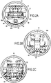
figure 2A est une vue de la machine selon les flèches A-A, la lame de raclage et la vis de chargement étant en position relevée ; - la
figure 2B est une vue de l'engin de curage selon les flèches B_B ; - la
figure 2C est une vue de l'engin de marinage selon les flèches C-C de lafigure 1 ; et - les
figures 3A et 3B sont des dessins simplifiés illustrant la mise en oeuvre du procédé objet de l'invention.
- the
figure 1 is a side view of the whole machine; - the
Figure 2A is a view of the machine according to the arrows AA, the scraping blade and the loading screw being in the raised position; - the
Figure 2B is a view of the cleaning machine according to arrows B_B; - the
Figure 2C is a view of the mariner according to the arrows CC of thefigure 1 ; and - the
Figures 3A and 3B are simplified drawings illustrating the implementation of the method which is the subject of the invention.
En se référant tout d'abord à la
Au dispositif de curage 24 est associé un premier moyen de transfert des sédiments et autres débris récupérés par la lame 26 qui porte la référence générale 36. De préférence, le premier dispositif de transfert 36 est constitué par une vis de chargement 38 disposée en relation avec la lame de curage 26. La vis de chargement 38 est constituée de préférence par deux portions d'extrémité 38a et 38b munies chacune d'une pale 37 et d'une partie centrale 38c dépourvue de pales. La fonction de la vis de chargement 38 est d'une part grâce à la présence des pales 37 de découper les morceaux de sédiments arrachés au fond de la galerie et d'autre part de ramener vers le centre ces morceaux de sédiments découpés. De préférence, un vérin 35 permet de déplacer la vis 38 d'une position relevée à une position abaissée de travail.The
Le premier moyen de transfert 36 comporte également un convoyeur 40 qui comporte une première extrémité 40a en regard de la vis de chargement 38 et de préférence solidaire de la lame 26 de raclage et une deuxième extrémité 40b. Bien entendu, aussi bien la vis de chargement 38 que le convoyeur 40 sont montés sur le châssis 14 de l'engin de curage. L'engin de curage comporte également à son extrémité arrière 42 une trémie tampon 44 qui constitue les premiers moyens de stockage. Cette partie qui est solidaire des trains de roues arrière 18 et 20 est de préférence articulée autour d'un axe vertical 46 par rapport à la partie avant de l'engin de curage 10. Cette articulation 46 permet de conformer l'engin de curage 10 au tracé de la galerie 30. De préférence, la trémie tampon 44 comporte un fond incliné 48. L'engin de curage 10 comporte également des deuxièmes moyens de transfert constitués par le convoyeur 50. Ce convoyeur 50 a une première partie 50a qui est disposée à l'intérieur de la trémie 44 à proximité de son fond 48 et une deuxième partie 50b extérieure à celle-ci. L'extrémité 50c du convoyeur 50 est disposée largement au-delà de l'extrémité arrière 44a de la trémie 44.The first transfer means 36 also comprises a
Comme on le voit mieux sur la
L'engin de curage 10 comporte bien sûr également une cabine 52 pour le pilotage de l'engin, des moteurs non représentés pour entraîner les trains de roues, ces moteurs étant par exemple hydrauliques. Le châssis 14 porte également des moyens d'alimentation en fluide sous pression pour commander la rotation de la vis de chargement 38, les vérins 34 et 35 de modification de la position de la lame de curage 26, et de la vis 38, ainsi que les convoyeurs 40 et 50.The
La machine de curage comporte également un deuxième mobile qui est constitué par l'engin de marinage 12 dont la fonction est comme on l'a indiqué de permettre le transfert des sédiments entre l'engin de curage 10 et une zone de déchargement prévue dans la galerie. L'engin de marinage 12 est constitué essentiellement par un châssis 52 équipé par exemple de quatre trains de roues 54, 56, 58 et 60.The cleaning machine also comprises a second mobile which is constituted by the pickling
Ces roues ont bien sûr également des axes de rotation inclinés par rapport à l'horizontal pour venir en appui sur les parois de la galerie. De préférence, ces roues viennent en appui sur cette paroi dans une position plus éloignée du fond de la galerie que les trains de roues 16 à 20 de l'engin de curage 10. En effet, on obtient ainsi de meilleures conditions de roulement de l'engin de marinage puisque le fond de la galerie peut présenter des inégalités. On comprend que cette disposition est particulièrement intéressante puisque si l'engin de curage 10 ne se déplace que très lentement et ne parcourt que la distance correspondant à la longueur de galerie à curer, l'engin de marinage 12 est amené à faire un grand nombre d'allers et retours entre l'engin de curage 10 et le point de déchargement. L'engin de marinage 12 est équipé d'une benne de stockage 62 qui est de préférence amovible par rapport au châssis 52 de l'engin de marinage 12. L'engin de marinage 12 est également équipé d'une cabine de pilotage 64 et de moteurs d'entraînement d'au moins certains des trains de roues 54 à 60.These wheels of course also have rotation axes inclined relative to the horizontal to bear against the walls of the gallery. Preferably, these wheels bear against this wall in a position farther from the bottom of the gallery than the wheel trains 16 to 20 of the
Ces roues peuvent être soit des roues standard, soit des roues à rouleaux du type décrit dans le brevet français
La vitesse de déplacement de l'engin de curage 10 en cours d'opération est bien sûr très limitée pour obtenir un curage efficace de la galerie. Par exemple, elle vaut 1 ou 2m/mn. En revanche, l'engin de marinage 12, pour faire ses allers et retours, peut bien sûr avoir une vitesse de déplacement plus élevée, par exemple de l'ordre de 15 km/h.The speed of movement of the cleaning
Pour obtenir une optimisation du fonctionnement de la machine de curage, il est souhaitable de définir convenablement la capacité volumique de la trémie 44 de l'engin de curage 10. Cette capacité volumique doit être au moins égale à la quantité de sédiments extraits par l'engin de curage 10 lorsque l'engin de marinage 12 parcourt le trajet aller et retour entre l'engin de curage 10 et le point de déchargement des sédiments lorsque l'engin de curage 10 est lui-même à la distance maximale du point de déchargement. Les premiers moyens de stockage (la trémie 44) constituent ainsi une zone tampon de rétention temporaire des produits de curage qui rend ainsi autonomes les deux engins mobiles. Il faut également bien sûr que la capacité de la benne 62 soit adaptée à celle de la trémie 44.For an optimization of the operation of the cleaning machine, it is desirable to define suitably the volume capacity of the
En se référant maintenant aux
Au fur et à mesure que les sédiments sont détachés par la lame de curage 26, ils sont transférés vers la trémie de stockage 44 à l'aide de la vis de chargement 38 et du premier convoyeur 40. Lorsque la trémie 44 est suffisamment pleine de sédiments, l'engin de marinage 12 qui est disposé à l'arrière de l'engin de curage 10 est rempli avec les sédiments par l'intermédiaire du deuxième convoyeur 50. On remplit ainsi la benne amovible 62 de l'engin de marinage 12. Lorsque cette opération est réalisée, le convoyeur 50 est arrêté et l'engin de marinage 12 se déplace jusqu'au point de déchargement P correspondant à un accès 64 dans la galerie 32. Lorsque l'engin de marinage 12 est arrivé en regard de l'accès 64, des moyens de levage 66 permettent d'extraire la benne amovible 62 pleine de sédiments ou déblais et de remplacer celle-ci par une benne vide 62 qui est mise en place sur le châssis de l'engin de marinage 12. Celui-ci retourne alors vers l'engin de curage 10 et il suit la progression lente de l'engin de curage 10. Lorsque la trémie 44 est remplie, on procède à nouveau au déchargement de celle-ci dans la benne 62 de l'engin de marinage 12 comme on l'a expliqué précédemment. Durant cette opération, le convoyeur 40 continue à transférer des sédiments dans la trémie 44. La quantité totale de sédiments transférée dans la benne 62 peut donc être celle qui était dans la trémie au début du transfert augmentée de la quantité de sédiments transférée dans la trémie durant cette opération de transfert.As the sediments are detached by the
On comprend que lorsque l'engin de curage 10 est éloigné de la distance maximale à laquelle il doit intervenir, par rapport au point de déchargement, les trajets réalisés par l'engin de marinage 12 sont relativement réduits et, en dehors des périodes d'allers et retours, l'engin de marinage suit l'engin de curage. En revanche, lorsque l'engin de curage 10 est proche de la distance maximale prévue de traitement de l'égout, l'engin de marinage 12 ne reste en station auprès de l'engin de curage que sensiblement le temps de procéder au transfert des sédiments ou déblais de la trémie 44 vers la benne 62 à l'aide du convoyeur 50.It is understood that when the cleaning
On a décrit ci-dessus un mode préféré de réalisation de l'invention. Il va cependant de soi que de nombreuses variantes pourraient être envisagées. En particulier, les mobiles constitués par l'engin de curage 10 et l'engin de marinage 12 pourraient ne pas être automoteurs et être entraînés par des moyens de propulsion externes. Ou bien, l'engin de curage 10 et l'engin de marinage 12 pourraient être automoteurs mais commandés automatiquement à distance.A preferred embodiment of the invention has been described above. It goes without saying, however, that many variants could be envisaged. In particular, the mobiles constituted by the cleaning
Il serait également possible de prévoir que, au lieu que les deuxièmes moyens de transfert de sédiments constitués par le convoyeur 50 ne soient montés sur l'engin de curage 10 comme cela a été décrit précédemment, ces deuxièmes moyens de transfert soient montés sur l'engin de marinage. Dans ce cas, ces deuxièmes moyens de transfert pourraient consister par exemple en une conduite d'aspiration ou en un système à vis de transfert des sédiments de la trémie 44 vers la benne 62.It would also be possible to provide that, instead of the second sediment transfer means constituted by the
Dans certaines phases de fonctionnement de la machine, l'engin de marinage 12 peut également servir à transporter du combustible pour l'engin de curage 10, du personnel, ou encore différents éléments de maintenance de l'engin de curage.In certain phases of operation of the machine, the pickling
Claims (9)
- A machine for scraping away sediment or the like deposited on the bottom of a gallery, the machine being characterized in that it comprises:• a first movable body (10) suitable for moving over the bottom portion of the wall of the gallery, said first movable body presenting a front and a rear;• first movement means (16, 18, 20) for enabling said first movable body to move on the bottom portion of the wall of the gallery;• scraper means (26) for detaching sediment from the bottom of the gallery and mounted at the front of said first movable body;• first buffer storage means (44) mounted on said first movable body (10);• first transfer means (36) for transferring detached sediment into said first buffer storage means;• second transfer means (50) for transferring sediment stored in said first buffer storage means (44) to the outside of said first movable body;• a second movable body (12) distinct from the first movable body, and suitable for moving along the bottom portion of the wall of the gallery;• second movement means (54, 56, 58, 60) for enabling said second movable body to move on the bottom portion of the wall of the gallery; and• second storage means (62) mounted on said second movable body to collect the sediment transferred to the outside of the first movable body by second transfer means.
- A machine according to claim 1, characterized in that the first movement means (16, 18, 20) are first motor means mounted on the first movable body.
- A machine according to claim 1 or claim 2, characterized in that the second movement means (54, 56, 58, 60) are second motor means mounted on the second movable body.
- A machine according to any one of claims 1 to 3, characterized in that the first transfer means (36) comprise a loader auger placed in register with the scraper means and/or a conveyor (50) having a first end co-operating with the loader auger and/or the scraper means, and the second end that is located above the first buffer storage means.
- A machine according to any one of claims 1 to 4, characterized in that said first buffer storage means (44) are located at the rear of the first movable body.
- A machine according to any one of claims 1 to 5, characterized in that the second transfer means (50) are mounted on said first movable body.
- A machine according to any one of claims 1 to 6, characterized in that said second storage means (62) are removable relative to said second movable body.
- A machine according to any one of claims 1 to 7, characterized in that said first buffer storage means (44) comprise a buffer tank.
- A method of scraping sediment or the like deposited on the bottom of a gallery, the method being characterized in that it comprises the following steps:• moving a first movable body provided with scraper means on the bottom portion of the gallery;• storing sediment on said movable body as it is removed;• moving a second movable body on the bottom portion of the wall of the gallery;• periodically transferring the sediment stored on the first movable body to the second movable body while the second movable body is kept close to the first movable body;• after the sediment has been transferred, moving the second movable body between its position close to the first movable body to a second stationary position for unloading the sediment stored on said second movable body to the outside of the gallery; and• returning said second movable body towards its position close to the first movable body;whereby the first movable body can perform the scraping operation continuously, including during stages of unloading the sediment with the help of the second movable body.
Applications Claiming Priority (1)
| Application Number | Priority Date | Filing Date | Title |
|---|---|---|---|
| FR0851605A FR2928669B1 (en) | 2008-03-12 | 2008-03-12 | CURING MACHINE |
Publications (3)
| Publication Number | Publication Date |
|---|---|
| EP2101005A2 EP2101005A2 (en) | 2009-09-16 |
| EP2101005A3 EP2101005A3 (en) | 2012-11-07 |
| EP2101005B1 true EP2101005B1 (en) | 2018-02-21 |
Family
ID=39864918
Family Applications (1)
| Application Number | Title | Priority Date | Filing Date |
|---|---|---|---|
| EP09154545.9A Not-in-force EP2101005B1 (en) | 2008-03-12 | 2009-03-06 | Dredging machine and method of dredging |
Country Status (4)
| Country | Link |
|---|---|
| US (1) | US8276600B2 (en) |
| EP (1) | EP2101005B1 (en) |
| FR (1) | FR2928669B1 (en) |
| SG (1) | SG155857A1 (en) |
Families Citing this family (4)
| Publication number | Priority date | Publication date | Assignee | Title |
|---|---|---|---|---|
| CN102155219B (en) * | 2011-03-29 | 2013-07-17 | 大同煤矿集团衡安装备有限公司 | Comprehensive dredging machine |
| CN104110065B (en) * | 2014-07-24 | 2015-08-05 | 靖江康泰环保设备有限公司 | A kind of sewer remote sensing trash rake |
| CN110952650A (en) * | 2019-12-09 | 2020-04-03 | 李晓婷 | Municipal administration environmental protection pipeline desilting device |
| CN111851723B (en) * | 2020-07-22 | 2021-07-23 | 湖州建烨自动化科技有限公司 | Be used for road sewer pull throughs |
Family Cites Families (16)
| Publication number | Priority date | Publication date | Assignee | Title |
|---|---|---|---|---|
| US3138327A (en) * | 1962-01-15 | 1964-06-23 | Jacobs J Donovan | Movable trackways for tunnels and method for moving tunnel flooring |
| DE1188026B (en) * | 1962-06-01 | 1965-03-04 | Atlas Copco Ab | Method and device for moving empty wagons in single-lane drifts |
| US4007963A (en) * | 1975-05-16 | 1977-02-15 | Occidental Petroleum Corporation | Oil collection and recovery system for in situ oil shale retort |
| CA990317A (en) * | 1975-07-11 | 1976-06-01 | Bernard Desourdy | Trackless train system |
| FR2693220B1 (en) * | 1992-07-06 | 1994-08-19 | Sacavi Sa | Process for cleaning up works, especially sewers. |
| FR2701278B1 (en) * | 1993-02-05 | 1995-04-21 | Jean Roche | Cleaning process and cleaning and inspection device for sewer collectors. |
| JP2770765B2 (en) * | 1995-02-24 | 1998-07-02 | 株式会社本間組 | High concentration dredging equipment |
| US5815654A (en) * | 1996-05-20 | 1998-09-29 | Chrysler Corporation | Method for determining software reliability |
| JPH1121986A (en) * | 1997-07-01 | 1999-01-26 | Akiyoshi Hirata | Truck for earth and sand transportation and sewage pipe transportation platform |
| JP2000282440A (en) * | 1999-03-29 | 2000-10-10 | Hitachi Kiden Kogyo Ltd | Screened matter storing system |
| US6934934B1 (en) * | 1999-08-30 | 2005-08-23 | Empirix Inc. | Method and system for software object testing |
| JP2001311214A (en) * | 2000-04-27 | 2001-11-09 | Nikki Plan Tec Kk | Storage hopper |
| FR2808491B1 (en) | 2000-05-04 | 2002-08-09 | Cie Du Sol | A SELF-PROPELLED TROLLEY CAPABLE OF MOVING IN A CYLINDRICAL GALLERY |
| US6738938B2 (en) * | 2002-05-29 | 2004-05-18 | Logicvision, Inc. | Method for collecting failure information for a memory using an embedded test controller |
| US20070061625A1 (en) * | 2005-09-15 | 2007-03-15 | Acosta Juan Jr | Automation structure for software verification testing |
| US20070220370A1 (en) * | 2006-01-12 | 2007-09-20 | International Business Machines Corporation | Mechanism to generate functional test cases for service oriented architecture (SOA) applications from errors encountered in development and runtime |
-
2008
- 2008-03-12 FR FR0851605A patent/FR2928669B1/en not_active Expired - Fee Related
-
2009
- 2009-03-06 EP EP09154545.9A patent/EP2101005B1/en not_active Not-in-force
- 2009-03-10 SG SG200901816-9A patent/SG155857A1/en unknown
- 2009-03-12 US US12/402,995 patent/US8276600B2/en active Active
Non-Patent Citations (1)
| Title |
|---|
| None * |
Also Published As
| Publication number | Publication date |
|---|---|
| SG155857A1 (en) | 2009-10-29 |
| EP2101005A3 (en) | 2012-11-07 |
| EP2101005A2 (en) | 2009-09-16 |
| US20090229631A1 (en) | 2009-09-17 |
| US8276600B2 (en) | 2012-10-02 |
| FR2928669A1 (en) | 2009-09-18 |
| FR2928669B1 (en) | 2012-01-13 |
Similar Documents
| Publication | Publication Date | Title |
|---|---|---|
| EP0980721B1 (en) | Mobile device for cleaning constructions for the transport of fluids, in particular sewers | |
| EP2101005B1 (en) | Dredging machine and method of dredging | |
| EP0155869A1 (en) | Installation for the extraction of minerals from the sea-bed | |
| FR2472058A1 (en) | METHOD AND APPARATUS FOR HOLLOWING VERY VERY VERY PARALLEL WALL TRENCHES IN THE GROUND | |
| EP0018891B1 (en) | Submarine vehicle for dredging and lifting minerals at a great depth | |
| KR20090027495A (en) | Dredging machine for sewerage | |
| EP3903923B1 (en) | Method for complete draining of a catalytic reactor by means of an articulated arm provided with rotary spiral protrusions | |
| EP0187174A1 (en) | Mobile cleaning installation for portable containers, e.g. waste bins | |
| WO2013057442A1 (en) | Large-diameter drilling device | |
| FR2606051A1 (en) | ENGINE OF PUBLIC WORKS FOR THE PRODUCTION OF TRENCHES | |
| CH657649A5 (en) | Railway site machine for the at least partial repair of a railway track portion | |
| FR2497779A1 (en) | LOADING AND TRANSPORT TRAIN, PARTICULARLY FOR TUNNEL CLEARING, AND METHOD FOR IMPLEMENTING SAME | |
| FR2701278A1 (en) | Process for cleaning and device for cleaning and inspecting mains sewers (drains) | |
| EP0152643A1 (en) | Travelling machine for removing ballast from rail tracks | |
| FR2971492A1 (en) | COMPACTION TANK FOR THE COLLECTION OF A HOUSEHOLD TYPE WASTE LOAD AND METHOD OF TRANSFERRING THE LOAD OF SUCH A TANK TO A CONTAINER | |
| CH629556A5 (en) | Device for removing snow | |
| CN211922946U (en) | Dredging and slag-removing equipment for sewer well pipeline | |
| EP0170108B1 (en) | Machine for reclaiming constituents of concrete | |
| FR2638178A1 (en) | Device for scraping out and removing mud (sludge) which is sedimented on the bottom of a stretch of water | |
| FR2565290A1 (en) | Method and device for boring wells | |
| JPH09250167A (en) | Side ditch cleaning machine | |
| FR2777875A1 (en) | Installation for emptying drums of viscous fluid e.g. waste material or toxic material | |
| FR2731728A1 (en) | Scoop for drainage trench excavator | |
| FR2824814A1 (en) | Equipment for washing recycling bins is mounted on lorry and comprises open tank containing rotating spray mounted on lift for washing inside of bin and rotating rollers to wash its outside | |
| FR2967426A1 (en) | Deep excavation dipper integrated boom for excavator on track to carry out earthworks, has hydraulic winch and winder/unwinder arranged at rear of line so as to be found outside vision field of operator, in operational position of boom |
Legal Events
| Date | Code | Title | Description |
|---|---|---|---|
| PUAI | Public reference made under article 153(3) epc to a published international application that has entered the european phase |
Free format text: ORIGINAL CODE: 0009012 |
|
| AK | Designated contracting states |
Kind code of ref document: A2 Designated state(s): AT BE BG CH CY CZ DE DK EE ES FI FR GB GR HR HU IE IS IT LI LT LU LV MC MK MT NL NO PL PT RO SE SI SK TR |
|
| AX | Request for extension of the european patent |
Extension state: AL BA RS |
|
| RAP1 | Party data changed (applicant data changed or rights of an application transferred) |
Owner name: SOLETANCHE FREYSSINET |
|
| PUAL | Search report despatched |
Free format text: ORIGINAL CODE: 0009013 |
|
| AK | Designated contracting states |
Kind code of ref document: A3 Designated state(s): AT BE BG CH CY CZ DE DK EE ES FI FR GB GR HR HU IE IS IT LI LT LU LV MC MK MT NL NO PL PT RO SE SI SK TR |
|
| AX | Request for extension of the european patent |
Extension state: AL BA RS |
|
| RIC1 | Information provided on ipc code assigned before grant |
Ipc: E03F 7/10 20060101AFI20121001BHEP Ipc: E03F 9/00 20060101ALI20121001BHEP |
|
| 17P | Request for examination filed |
Effective date: 20130412 |
|
| AKX | Designation fees paid |
Designated state(s): AT BE BG CH CY CZ DE DK EE ES FI FR GB GR HR HU IE IS IT LI LT LU LV MC MK MT NL NO PL PT RO SE SI SK TR |
|
| GRAP | Despatch of communication of intention to grant a patent |
Free format text: ORIGINAL CODE: EPIDOSNIGR1 |
|
| INTG | Intention to grant announced |
Effective date: 20170912 |
|
| GRAS | Grant fee paid |
Free format text: ORIGINAL CODE: EPIDOSNIGR3 |
|
| GRAA | (expected) grant |
Free format text: ORIGINAL CODE: 0009210 |
|
| AK | Designated contracting states |
Kind code of ref document: B1 Designated state(s): AT BE BG CH CY CZ DE DK EE ES FI FR GB GR HR HU IE IS IT LI LT LU LV MC MK MT NL NO PL PT RO SE SI SK TR |
|
| REG | Reference to a national code |
Ref country code: GB Ref legal event code: FG4D Free format text: NOT ENGLISH |
|
| REG | Reference to a national code |
Ref country code: CH Ref legal event code: EP |
|
| REG | Reference to a national code |
Ref country code: AT Ref legal event code: REF Ref document number: 971874 Country of ref document: AT Kind code of ref document: T Effective date: 20180315 |
|
| REG | Reference to a national code |
Ref country code: IE Ref legal event code: FG4D Free format text: LANGUAGE OF EP DOCUMENT: FRENCH |
|
| REG | Reference to a national code |
Ref country code: DE Ref legal event code: R096 Ref document number: 602009050809 Country of ref document: DE |
|
| REG | Reference to a national code |
Ref country code: FR Ref legal event code: PLFP Year of fee payment: 10 |
|
| REG | Reference to a national code |
Ref country code: NL Ref legal event code: MP Effective date: 20180221 |
|
| REG | Reference to a national code |
Ref country code: LT Ref legal event code: MG4D |
|
| REG | Reference to a national code |
Ref country code: AT Ref legal event code: MK05 Ref document number: 971874 Country of ref document: AT Kind code of ref document: T Effective date: 20180221 |
|
| PG25 | Lapsed in a contracting state [announced via postgrant information from national office to epo] |
Ref country code: FI Free format text: LAPSE BECAUSE OF FAILURE TO SUBMIT A TRANSLATION OF THE DESCRIPTION OR TO PAY THE FEE WITHIN THE PRESCRIBED TIME-LIMIT Effective date: 20180221 Ref country code: HR Free format text: LAPSE BECAUSE OF FAILURE TO SUBMIT A TRANSLATION OF THE DESCRIPTION OR TO PAY THE FEE WITHIN THE PRESCRIBED TIME-LIMIT Effective date: 20180221 Ref country code: NO Free format text: LAPSE BECAUSE OF FAILURE TO SUBMIT A TRANSLATION OF THE DESCRIPTION OR TO PAY THE FEE WITHIN THE PRESCRIBED TIME-LIMIT Effective date: 20180521 Ref country code: NL Free format text: LAPSE BECAUSE OF FAILURE TO SUBMIT A TRANSLATION OF THE DESCRIPTION OR TO PAY THE FEE WITHIN THE PRESCRIBED TIME-LIMIT Effective date: 20180221 Ref country code: ES Free format text: LAPSE BECAUSE OF FAILURE TO SUBMIT A TRANSLATION OF THE DESCRIPTION OR TO PAY THE FEE WITHIN THE PRESCRIBED TIME-LIMIT Effective date: 20180221 Ref country code: LT Free format text: LAPSE BECAUSE OF FAILURE TO SUBMIT A TRANSLATION OF THE DESCRIPTION OR TO PAY THE FEE WITHIN THE PRESCRIBED TIME-LIMIT Effective date: 20180221 Ref country code: CY Free format text: LAPSE BECAUSE OF FAILURE TO SUBMIT A TRANSLATION OF THE DESCRIPTION OR TO PAY THE FEE WITHIN THE PRESCRIBED TIME-LIMIT Effective date: 20180221 |
|
| PG25 | Lapsed in a contracting state [announced via postgrant information from national office to epo] |
Ref country code: BG Free format text: LAPSE BECAUSE OF FAILURE TO SUBMIT A TRANSLATION OF THE DESCRIPTION OR TO PAY THE FEE WITHIN THE PRESCRIBED TIME-LIMIT Effective date: 20180521 Ref country code: GR Free format text: LAPSE BECAUSE OF FAILURE TO SUBMIT A TRANSLATION OF THE DESCRIPTION OR TO PAY THE FEE WITHIN THE PRESCRIBED TIME-LIMIT Effective date: 20180522 Ref country code: LV Free format text: LAPSE BECAUSE OF FAILURE TO SUBMIT A TRANSLATION OF THE DESCRIPTION OR TO PAY THE FEE WITHIN THE PRESCRIBED TIME-LIMIT Effective date: 20180221 Ref country code: SE Free format text: LAPSE BECAUSE OF FAILURE TO SUBMIT A TRANSLATION OF THE DESCRIPTION OR TO PAY THE FEE WITHIN THE PRESCRIBED TIME-LIMIT Effective date: 20180221 Ref country code: AT Free format text: LAPSE BECAUSE OF FAILURE TO SUBMIT A TRANSLATION OF THE DESCRIPTION OR TO PAY THE FEE WITHIN THE PRESCRIBED TIME-LIMIT Effective date: 20180221 |
|
| PG25 | Lapsed in a contracting state [announced via postgrant information from national office to epo] |
Ref country code: MT Free format text: LAPSE BECAUSE OF FAILURE TO SUBMIT A TRANSLATION OF THE DESCRIPTION OR TO PAY THE FEE WITHIN THE PRESCRIBED TIME-LIMIT Effective date: 20180221 |
|
| REG | Reference to a national code |
Ref country code: DE Ref legal event code: R119 Ref document number: 602009050809 Country of ref document: DE |
|
| PG25 | Lapsed in a contracting state [announced via postgrant information from national office to epo] |
Ref country code: PL Free format text: LAPSE BECAUSE OF FAILURE TO SUBMIT A TRANSLATION OF THE DESCRIPTION OR TO PAY THE FEE WITHIN THE PRESCRIBED TIME-LIMIT Effective date: 20180221 Ref country code: EE Free format text: LAPSE BECAUSE OF FAILURE TO SUBMIT A TRANSLATION OF THE DESCRIPTION OR TO PAY THE FEE WITHIN THE PRESCRIBED TIME-LIMIT Effective date: 20180221 Ref country code: IT Free format text: LAPSE BECAUSE OF FAILURE TO SUBMIT A TRANSLATION OF THE DESCRIPTION OR TO PAY THE FEE WITHIN THE PRESCRIBED TIME-LIMIT Effective date: 20180221 Ref country code: RO Free format text: LAPSE BECAUSE OF FAILURE TO SUBMIT A TRANSLATION OF THE DESCRIPTION OR TO PAY THE FEE WITHIN THE PRESCRIBED TIME-LIMIT Effective date: 20180221 |
|
| REG | Reference to a national code |
Ref country code: CH Ref legal event code: PL |
|
| PG25 | Lapsed in a contracting state [announced via postgrant information from national office to epo] |
Ref country code: MC Free format text: LAPSE BECAUSE OF FAILURE TO SUBMIT A TRANSLATION OF THE DESCRIPTION OR TO PAY THE FEE WITHIN THE PRESCRIBED TIME-LIMIT Effective date: 20180221 Ref country code: CZ Free format text: LAPSE BECAUSE OF FAILURE TO SUBMIT A TRANSLATION OF THE DESCRIPTION OR TO PAY THE FEE WITHIN THE PRESCRIBED TIME-LIMIT Effective date: 20180221 Ref country code: SK Free format text: LAPSE BECAUSE OF FAILURE TO SUBMIT A TRANSLATION OF THE DESCRIPTION OR TO PAY THE FEE WITHIN THE PRESCRIBED TIME-LIMIT Effective date: 20180221 Ref country code: DK Free format text: LAPSE BECAUSE OF FAILURE TO SUBMIT A TRANSLATION OF THE DESCRIPTION OR TO PAY THE FEE WITHIN THE PRESCRIBED TIME-LIMIT Effective date: 20180221 |
|
| REG | Reference to a national code |
Ref country code: BE Ref legal event code: MM Effective date: 20180331 |
|
| REG | Reference to a national code |
Ref country code: IE Ref legal event code: MM4A |
|
| PLBE | No opposition filed within time limit |
Free format text: ORIGINAL CODE: 0009261 |
|
| STAA | Information on the status of an ep patent application or granted ep patent |
Free format text: STATUS: NO OPPOSITION FILED WITHIN TIME LIMIT |
|
| PG25 | Lapsed in a contracting state [announced via postgrant information from national office to epo] |
Ref country code: LU Free format text: LAPSE BECAUSE OF NON-PAYMENT OF DUE FEES Effective date: 20180306 |
|
| 26N | No opposition filed |
Effective date: 20181122 |
|
| GBPC | Gb: european patent ceased through non-payment of renewal fee |
Effective date: 20180521 |
|
| PG25 | Lapsed in a contracting state [announced via postgrant information from national office to epo] |
Ref country code: DE Free format text: LAPSE BECAUSE OF NON-PAYMENT OF DUE FEES Effective date: 20181002 Ref country code: IE Free format text: LAPSE BECAUSE OF NON-PAYMENT OF DUE FEES Effective date: 20180306 |
|
| PG25 | Lapsed in a contracting state [announced via postgrant information from national office to epo] |
Ref country code: BE Free format text: LAPSE BECAUSE OF NON-PAYMENT OF DUE FEES Effective date: 20180331 Ref country code: CH Free format text: LAPSE BECAUSE OF NON-PAYMENT OF DUE FEES Effective date: 20180331 Ref country code: LI Free format text: LAPSE BECAUSE OF NON-PAYMENT OF DUE FEES Effective date: 20180331 Ref country code: SI Free format text: LAPSE BECAUSE OF FAILURE TO SUBMIT A TRANSLATION OF THE DESCRIPTION OR TO PAY THE FEE WITHIN THE PRESCRIBED TIME-LIMIT Effective date: 20180221 |
|
| PG25 | Lapsed in a contracting state [announced via postgrant information from national office to epo] |
Ref country code: GB Free format text: LAPSE BECAUSE OF NON-PAYMENT OF DUE FEES Effective date: 20180521 |
|
| PG25 | Lapsed in a contracting state [announced via postgrant information from national office to epo] |
Ref country code: TR Free format text: LAPSE BECAUSE OF FAILURE TO SUBMIT A TRANSLATION OF THE DESCRIPTION OR TO PAY THE FEE WITHIN THE PRESCRIBED TIME-LIMIT Effective date: 20180221 |
|
| PG25 | Lapsed in a contracting state [announced via postgrant information from national office to epo] |
Ref country code: HU Free format text: LAPSE BECAUSE OF FAILURE TO SUBMIT A TRANSLATION OF THE DESCRIPTION OR TO PAY THE FEE WITHIN THE PRESCRIBED TIME-LIMIT; INVALID AB INITIO Effective date: 20090306 Ref country code: PT Free format text: LAPSE BECAUSE OF FAILURE TO SUBMIT A TRANSLATION OF THE DESCRIPTION OR TO PAY THE FEE WITHIN THE PRESCRIBED TIME-LIMIT Effective date: 20180221 |
|
| PG25 | Lapsed in a contracting state [announced via postgrant information from national office to epo] |
Ref country code: MK Free format text: LAPSE BECAUSE OF NON-PAYMENT OF DUE FEES Effective date: 20180221 |
|
| PG25 | Lapsed in a contracting state [announced via postgrant information from national office to epo] |
Ref country code: IS Free format text: LAPSE BECAUSE OF FAILURE TO SUBMIT A TRANSLATION OF THE DESCRIPTION OR TO PAY THE FEE WITHIN THE PRESCRIBED TIME-LIMIT Effective date: 20180621 |
|
| PGFP | Annual fee paid to national office [announced via postgrant information from national office to epo] |
Ref country code: FR Payment date: 20210218 Year of fee payment: 13 |
|
| PG25 | Lapsed in a contracting state [announced via postgrant information from national office to epo] |
Ref country code: FR Free format text: LAPSE BECAUSE OF NON-PAYMENT OF DUE FEES Effective date: 20220331 |