EP2099656B1 - Generatorbaugruppe für ein airbagmodul eines kraftfahrzeugs - Google Patents
Generatorbaugruppe für ein airbagmodul eines kraftfahrzeugs Download PDFInfo
- Publication number
- EP2099656B1 EP2099656B1 EP07822773A EP07822773A EP2099656B1 EP 2099656 B1 EP2099656 B1 EP 2099656B1 EP 07822773 A EP07822773 A EP 07822773A EP 07822773 A EP07822773 A EP 07822773A EP 2099656 B1 EP2099656 B1 EP 2099656B1
- Authority
- EP
- European Patent Office
- Prior art keywords
- gas generator
- airbag
- generator
- gas
- material layer
- Prior art date
- Legal status (The legal status is an assumption and is not a legal conclusion. Google has not performed a legal analysis and makes no representation as to the accuracy of the status listed.)
- Not-in-force
Links
- 239000000463 material Substances 0.000 claims description 31
- 238000010292 electrical insulation Methods 0.000 claims description 6
- 239000004744 fabric Substances 0.000 claims description 4
- 239000011796 hollow space material Substances 0.000 claims 3
- 239000004020 conductor Substances 0.000 claims 2
- 230000009897 systematic effect Effects 0.000 claims 1
- 239000007789 gas Substances 0.000 description 134
- 230000001681 protective effect Effects 0.000 description 13
- 239000002184 metal Substances 0.000 description 2
- 239000000203 mixture Substances 0.000 description 2
- 230000004048 modification Effects 0.000 description 2
- 238000012986 modification Methods 0.000 description 2
- 230000007704 transition Effects 0.000 description 2
- 230000000712 assembly Effects 0.000 description 1
- 238000000429 assembly Methods 0.000 description 1
- 239000011324 bead Substances 0.000 description 1
- 238000005253 cladding Methods 0.000 description 1
- 238000010276 construction Methods 0.000 description 1
- 238000002347 injection Methods 0.000 description 1
- 239000007924 injection Substances 0.000 description 1
- 238000009413 insulation Methods 0.000 description 1
- 238000002955 isolation Methods 0.000 description 1
- 238000004519 manufacturing process Methods 0.000 description 1
- 239000002991 molded plastic Substances 0.000 description 1
- 239000000126 substance Substances 0.000 description 1
- 230000001960 triggered effect Effects 0.000 description 1
Images

Classifications
-
- B—PERFORMING OPERATIONS; TRANSPORTING
- B60—VEHICLES IN GENERAL
- B60R—VEHICLES, VEHICLE FITTINGS, OR VEHICLE PARTS, NOT OTHERWISE PROVIDED FOR
- B60R21/00—Arrangements or fittings on vehicles for protecting or preventing injuries to occupants or pedestrians in case of accidents or other traffic risks
- B60R21/02—Occupant safety arrangements or fittings, e.g. crash pads
- B60R21/16—Inflatable occupant restraints or confinements designed to inflate upon impact or impending impact, e.g. air bags
- B60R21/20—Arrangements for storing inflatable members in their non-use or deflated condition; Arrangement or mounting of air bag modules or components
- B60R21/217—Inflation fluid source retainers, e.g. reaction canisters; Connection of bags, covers, diffusers or inflation fluid sources therewith or together
-
- B—PERFORMING OPERATIONS; TRANSPORTING
- B60—VEHICLES IN GENERAL
- B60R—VEHICLES, VEHICLE FITTINGS, OR VEHICLE PARTS, NOT OTHERWISE PROVIDED FOR
- B60R21/00—Arrangements or fittings on vehicles for protecting or preventing injuries to occupants or pedestrians in case of accidents or other traffic risks
- B60R21/01—Electrical circuits for triggering passive safety arrangements, e.g. airbags, safety belt tighteners, in case of vehicle accidents or impending vehicle accidents
- B60R2021/01006—Mounting of electrical components in vehicles
Definitions
- the invention relates to a generator assembly for an airbag module of a motor vehicle according to the preamble of claim 1.
- Such a generator assembly comprises a gas generator for inflating a gas bag containing the gas bag of the airbag module with gas and means for electrically insulating the (a metallic housing having) gas generator with respect to adjacent (metallic) components of the airbag module.
- Such generator assemblies are for example from the publications DE 102 34 502 A1 and DE 103 57 867 A1 known.
- An airbag module in which said generator assembly can be used serves to protect vehicle occupants in the event of a crash.
- the gas generator of the airbag module is coupled with one or more crash and / or pre-crash sensors, which cause an ignition of the gas generator in a crash-related strong vehicle deceleration or on the basis of sensor data impending crash, so that this gas to inflate the airbag releases.
- the initially provided in collapsed or fauxgerafftem state in the airbag module airbag unfolds when inflated and forms in the inflated state, a gas cushion that should protect one or more vehicle occupants from hitting the vehicle body.
- this is usually the case electrically, that is, via electrical lines, connected to a control device which causes an ignition of the gas generator due to corresponding sensor signals.
- the aim here is to electrically isolate the gas generator, that is, in particular a metallic housing of the gas generator with respect to adjacent (metallic) Bauelenenten, so that a necessary grounding of the gas generator takes place exclusively targeted.
- the gas generator that is, in particular a metallic housing of the gas generator with respect to adjacent (metallic) Bauelenenten
- mounting parts and fasteners that are in contact with the gas generator, so in particular its (metallic) housing, electrically insulating form and provided, for example, with molded plastic areas.
- this requires an increased effort in the production and requires the use of complicated mounting hardware and fasteners.
- the invention is therefore based on the problem to provide a generator assembly of the type mentioned above, which is characterized by a simple construction by a reliable electrical insulation of the gas generator.
- a flexible material layer in particular in the form of a fabric layer, which completely encloses the gas generator (on an outside of the gas generator) along a circumferential direction.
- the grounding of a relative to surrounding components electrically insulated gas generator is effected by a grounding line, which contacts a (multi-pin) connector portion of the gas generator, which also serves to ignite the gas generator by means of sensor-controlled electrical signals.
- the gas generator By the gas generator is surrounded on its outside formed by a (metallic) housing by a flexible material layer, a direct contact of adjacent (metallic) components is prevented with the gas generator, since the flexible material layer shields the gas generator against such contact by between is formed by the (metallic) generator housing outside of the gas generator and adjacent thereto other components.
- the flexible Material layer forms a surrounding the gas generator in the circumferential direction flexible sheath that can be pushed, for example, on the associated gas generator.
- the arrangement according to the invention for isolating a gas generator is e.g. suitable for use with gas generators that extend along an axis, such.
- B. a so-called tubular gas generator having a substantially cylindrical lateral surface which extends between a first and a second end-side cover surface.
- a sheath made of a flexible material that forms a hollow cylinder and is open on at least one cover surface (with a proper arrangement on the associated gas generator) can be pulled over the gas generator in a simple manner.
- a maximum protection of the gas generator from electrical contact with adjacent components is achieved when the flexible material layer or casing along the longitudinal axis of the gas generator extends substantially along the entire length of the gas generator, so that the lateral surface of the gas generator along its entire length (ie completely) is covered by the flexible material layer.
- the flexible material layer may on the one hand be a section of the gas bag of the airbag module to be inflated by means of the gas generator, for example in that a section (extension) of the airbag is designed such that it surrounds the gas generator for insulation with respect to adjacent components.
- This arrangement is to be distinguished from the known case that a gas generator is disposed within the gas bag réelleblasenden hereby. Because in the latter case, the gas bag surrounding the gas generator is not used for electrical insulation of the gas generator relative to adjacent metallic components. In fact, it is essential for the flexible material layer according to the present invention that it also closely surrounds or bears against the gas generator in order to protect it from direct contact with neighboring components when the gas bag is inflated in a crash situation unfolds here.
- the flexible material layer surrounds the gas generator (permanently, ie also when inflating the airbag) in cross-section substantially concentric; and the flexible material layer keeps its original spatial position (on the outside of the gas generator) when inflating the airbag, without unfolding or itself Substantially from the gas generator (especially its facing outside of the gas generator) to remove, so that a defined by the flexible material layer cavity is substantially completely filled by the gas generator.
- the flexible material layer insulating the gas generator from its surroundings can also be a separate layer from the gas bag, which is not connected to the gas bag to be inflated.
- the flexible material layer can form part of an enclosure surrounding the gas bag in the folded state.
- Such an envelope serves to receive the gas bag folded or gathered to form a gas bag package, in order to facilitate the stowage of the gas bag package in the motor vehicle.
- Such a cladding of the airbag may for example consist of a film which ruptures during inflation and deployment of the airbag.
- the flexible material layer insulating the gas generator from its surroundings does not form part of another component of the airbag module, but is provided as an independent module component.
- the flexible material layer serves in particular to prevent direct contact of the surface (outer side) of the gas generator with components of a holding device, via which the gas generator is connected to an associated carrying motor vehicle part in order to fix its position within the motor vehicle, wherein it carrying motor vehicle part can also act on a component of the airbag module, such as a housing part of the airbag module.
- the flexible material layer extends between the gas generator and the holding device, so that a direct contact of the gas generator with the associated holding device, which regularly consists of metal for stability reasons, is avoided.
- the holding device may for example comprise a clamping section at least partially enclosing the gas generator, which is clamped by means of associated clamping elements on the gas generator, wherein the flexible material layer extends between the clamping portion of the holding device and the outside of the gas generator.
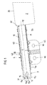
- FIG. 1 are of an airbag module for a motor vehicle, a gas generator 1, a ceremonisublasender by means of the gas generator in a crash case 2 with an airbag cover 20, a fabric layer 3 for electrical insulation of the gas generator 1 and a gas generator 1 associated holding device 4 shown.
- the gas generator 1 is a so-called tubular gas generator, which is surrounded by a tubular, substantially hollow cylindrical metallic housing 10 and with this defining a cylindrical surface generator housing 10 of length I between a first end-side top surface 11 and a second end face Deck surface 12 along an axis A extends.
- the gas generator 1 is used to inflate the associated airbag 2 in a crash case by the shell 20 of the airbag 2 (airbag shell) is filled by means of the gas generator 1 with gas.
- the gas bag 2 is located here in front of the second front-side cover surface 12 of the gas generator 1 by way of example.
- gas generator 1 From the gas bag 2 is in the direction of the gas generator 1 from an educated as an extension airbag section 3, which forms a gas generator 1 enclosing the flexible protective cover 30 which, like the airbag cover 20 of a fabric or, more precisely, is formed together with the airbag skin 20 from a suitable (uniform) tissue.
- the extension 3 of the airbag 2 forming flexible protective cover 30 extends as well as the (tubular) gas generator 1 between a first top surface 31 and a second top surface 32, wherein the first (open) top surface 31 of the flexible protective cover 30, the first end-side top surface 11 of Surrounding gas generator 1 and the second (also open) top surface 32 of the flexible protective cover 3 is located on the second end-side cover surface 12 of the gas generator 1 and forms a transition to the airbag cover 20.
- the flexible protective cover 30 of the gas generator 1 is a substantially hollow cylindrical extension of the airbag 2, such that the airbag cover 20 and the flexible protective cover 30 form a common cavity and that region of the cavity, which is enclosed by the airbag cover 20 , for filling with gas in a crash case, while that portion of the cavity, which is enclosed by the flexible protective cover 30, the inclusion of the gas generator 1 is used, wherein the flexible protective cover 30, the generator housing 10 so tightly encloses that the flexible protective cover 30 rests on the generator housing 10.
- the gas generator 1 or its housing 10 is electrically insulated from adjacent (metallic) components. This applies in particular to components of a holding device 4, via which the gas generator 1 can be fixed in a motor vehicle in a defined position.
- the holding device 4 has a gas generator 1 annularly at an angle of less than 360 °, but preferably at an angle of at least 180 ° surrounding clamping portion 40 by means of two Kiemmimplantation 5a, 5b in the form of clamping rings on the gas generator 1 and more precisely whose housing 10 is clamped.
- the gas generator 1 enclosing the flexible shell 30 extends between the housing 10 of the gas generator 1 on the one hand and the said components 5a, 5b, 40 of the holding device 4 on the other hand, so that these typically made of metal components have no direct contact with the metallic generator housing 10 ,
- the clamping portion 40 of the holding device 4 also has an annular circumferential projection 43 into which a bead of the generator housing 10 can engage to secure the clamping portion 40 in the axial direction (along the longitudinal axis A of the gas generator 1).
- clamping portion 40 of the holding device 4 is from a connecting portion 45, via which the clamped in the clamping portion 40 of the holding device 4 gas generator 1 is fixed to a supporting motor vehicle part, for which in the connecting portion 45 mounting holes 46 are provided by suitable fasteners, eg. B. in the form of screws can be penetrated.
- the flexible protective cover 30 is adapted in its cross section to the outer contour of the gas generator 1 facing it and the holding device 4 comprises the gas generator 1 and the flexible sleeve 30 with its clamping portion 40, the flexible sleeve 30 lies against the gas generator 1, more precisely at its formed by the generator housing 10 on the outside, so that the flexible protective cover 30 is filled by the gas generator 1 substantially completely, and even then, even if the airbag cover 20 is filled during inflation of the airbag 2 with gas.
- the gas generator 1 On its side facing away from the gas bag 2, the first end-side top surface 11, the gas generator 1 has a connector portion 15 which enables the electrical connection of a control unit with which the gas generator in response to output signals of one or more crash or pre-crash sensors triggered or is ignitable.
- a control unit with which the gas generator in response to output signals of one or more crash or pre-crash sensors triggered or is ignitable.
- electrical connecting lines electrical cables
- the plug region 15 of the gas generator 1 is here a multi-pin connector area, in addition to the electrical connection lines to an associated control unit and a grounding line is connected to ground the gas generator. This is combined with the isolation of the Gas generator 1 through the flexible protective cover 30 reaches a targeted, defined grounding of the gas generator 1.
- the plug region 15 of the gas generator 1 in the present case comprises three plug elements 15a, 15b, 15c, of which two plug elements 15a, 15b are provided in the form of plug pins for electrical connection of the gas generator 1 to an associated control unit (via electrical connection lines) and a further plug element 15c is used to ground the gas generator 1 via a to be connected to that connector element 15c and grounding therefrom, which is fed to a central vehicle ground.
- the third plug element 15c is in electrical contact with the (metallic) gas generator housing 10 and may be formed, for example, by an electrical contact section on the inner wall of the plug region 15 and / or on its front side. Both variants are in FIG. 1 indicated.
- FIG. 2 is a modification of the embodiment FIG. 1 represented, with a difference that according to FIG. 2 the gas bag 2 is surrounded by a folded or gathered state of an envelope 6 formed by a film 60 in an airbag package. This keeps the gas bag 2 in a compressed state to a package state and thus facilitates the stowage of the airbag 2 in a motor vehicle.
- the airbag 2 When inflating the airbag 2 in a crash case by the gas bag shell 20 surrounded by the interior of the airbag 2 is filled with gas, the airbag 2 unfolds, the envelope formed by the film 60 6 travels, so that the airbag. 2 emerge from the enclosure 6 and can form a cushion for serving a vehicle occupant.
- FIG. 1 shown embodiment consists in the generator assembly FIG. 2 in that the flexible protective cover 30 serving to isolate the gas generator 1 from adjacent components is not formed by an extension of the airbag 2 inflatable in a crash to a gas cushion but rather by an extension 3 of the envelope 6 surrounding the airbag 2 in a compressed state , D. h.,
- the extension 3 is connected to the envelope 6 forming film 60 (one piece), so that he preferably also is formed as a film part, and is from that film 60 in the direction of the gas generator 2 from.
- a transition region to the envelope 6 of the airbag 2 or, more precisely, to the envelope 6 forming the film 60 is formed on the second end-side cover surface 32 of the flexible shell 30.
- the airbag 2 or the airbag cover 20 in this case surrounds the gas generator 1 only partially in the region of its end face 12 facing the airbag 2 with an injection mouth 25 of the airbag 2.
- the above-described electrical insulation of the gas generator 1 with respect to adjacent components is independent of whether it is a hot gas generator which generates (chemically) hot gases to ignite the airbag 2 when ignited from a mixture of substances, or a cold gas generator which is ignited a gas already stored in the gas generator for inflating the airbag 2 releases, or to a so-called hybrid gas generator containing both a stored, releasable for inflating the airbag 2 cold gas and serving for generating additional hot gases mixture.
Landscapes
- Engineering & Computer Science (AREA)
- Mechanical Engineering (AREA)
- Air Bags (AREA)
Applications Claiming Priority (2)
| Application Number | Priority Date | Filing Date | Title |
|---|---|---|---|
| DE202006019196U DE202006019196U1 (de) | 2006-12-15 | 2006-12-15 | Generatorbaugruppe für ein Airbagmodul eines Kraftfahrzeugs |
| PCT/EP2007/062627 WO2008071525A1 (de) | 2006-12-15 | 2007-11-21 | Generatorbaugruppe für ein airbagmodul eines kraftfahrzeugs |
Publications (2)
| Publication Number | Publication Date |
|---|---|
| EP2099656A1 EP2099656A1 (de) | 2009-09-16 |
| EP2099656B1 true EP2099656B1 (de) | 2013-01-02 |
Family
ID=37983079
Family Applications (1)
| Application Number | Title | Priority Date | Filing Date |
|---|---|---|---|
| EP07822773A Not-in-force EP2099656B1 (de) | 2006-12-15 | 2007-11-21 | Generatorbaugruppe für ein airbagmodul eines kraftfahrzeugs |
Country Status (6)
| Country | Link |
|---|---|
| US (1) | US8047562B2 (enExample) |
| EP (1) | EP2099656B1 (enExample) |
| JP (1) | JP5230643B2 (enExample) |
| CN (1) | CN101583521B (enExample) |
| DE (1) | DE202006019196U1 (enExample) |
| WO (1) | WO2008071525A1 (enExample) |
Families Citing this family (3)
| Publication number | Priority date | Publication date | Assignee | Title |
|---|---|---|---|---|
| KR100962140B1 (ko) * | 2008-07-10 | 2010-06-10 | 현대자동차주식회사 | 차량의 혼 신호용 스위치 장치 |
| DE102009046841B4 (de) * | 2009-11-18 | 2017-04-27 | TAKATA Aktiengesellschaft | Airbag für ein Kraftfahrzeug |
| CN104169134B (zh) * | 2012-03-27 | 2017-03-15 | 株式会社大赛璐 | 气体发生器 |
Family Cites Families (23)
| Publication number | Priority date | Publication date | Assignee | Title |
|---|---|---|---|---|
| DE19742204B4 (de) * | 1997-09-24 | 2006-07-13 | Trw Airbag Systems Gmbh & Co. Kg | Gasgenerator für eine Sicherheitseinrichtung |
| JP2000085510A (ja) | 1998-09-14 | 2000-03-28 | Takata Kk | エアバッグ装置とインフレータとの連結構造 |
| DE19846110A1 (de) * | 1998-10-07 | 2000-04-20 | Bosch Gmbh Robert | Zündvorrichtung für Rückhaltemittel in einem Fahrzeug |
| JP3491228B2 (ja) * | 2000-05-26 | 2004-01-26 | 豊田合成株式会社 | 頭部保護エアバッグ装置 |
| DE10030471C1 (de) * | 2000-06-21 | 2001-07-26 | Bosch Gmbh Robert | Airbagmodul |
| US6450529B1 (en) | 2000-06-23 | 2002-09-17 | Breed Automotive Technologies, Inc. | Inflatable side air bag curtain module with chamber separators |
| DE10114208A1 (de) * | 2001-03-23 | 2002-05-08 | Trw Automotive Safety Sys Gmbh | Gassack-Modul |
| JP4061271B2 (ja) * | 2001-12-12 | 2008-03-12 | タカターペトリ(ウルム)ゲーエムベーハー | 自動車の乗員保護装置用モジュール |
| DE10234502A1 (de) | 2001-12-12 | 2003-07-03 | Takata Petri Gmbh Ulm | Modul für eine Insassenschutzvorrichtung eines Kraftfahrzeugs |
| DE10223829A1 (de) | 2002-05-28 | 2003-12-11 | Takata Petri Gmbh Ulm | Gasgenerator für einen Airbag |
| DE20220428U1 (de) | 2002-06-07 | 2003-07-17 | Autoliv Development Ab, Vargarda | Elektrisch isolierte Befestigungsanordnung für ein Airbagmodul |
| BRPI0311647A2 (pt) | 2002-06-07 | 2016-06-28 | Autoliv Dev | disposição de fixação eletricamente isolada para um módulo de air-bag |
| JP4059124B2 (ja) * | 2003-03-27 | 2008-03-12 | 豊田合成株式会社 | サイドエアバッグ装置及びそれに用いるラッピングシート |
| DE10357867B4 (de) | 2003-12-11 | 2006-08-10 | Autoliv Development Ab | Airbagmodul-Befestigungsanordnung mit Massekabel |
| US7384062B2 (en) | 2004-01-28 | 2008-06-10 | Nihon Plast Co., Ltd. | Airbag system |
| DE102004010144B4 (de) * | 2004-02-27 | 2006-03-23 | Zf Friedrichshafen Ag | Anordnung zur Festlegung des Gasgenerators einer Airbageinheit |
| DE102004015755B3 (de) | 2004-03-31 | 2005-09-08 | Autoliv Development Ab | Airbagmodul für Fahrzeuge |
| DE102005031108A1 (de) | 2004-07-09 | 2006-01-26 | Trw Automotive Gmbh | Gassackmodul |
| DE202004010785U1 (de) * | 2004-07-09 | 2004-11-25 | Trw Automotive Gmbh | Gassackmodul |
| DE202004016975U1 (de) * | 2004-11-01 | 2004-12-30 | Autoliv Development Ab | Airbagvorrichtung mit einem zerstörbaren Verbindungsabschnitt zwischen einem Gasgenerator und einer nichtmetallischen Gaslanze |
| DE102005004452A1 (de) | 2005-02-01 | 2006-08-10 | Adam Opel Ag | Airbaggehäuse, Airbagmodul und Sicherheitsanordnung zur Gewährleistung der ordnungsgemäßen Funktion des Gasgenerators in einem Airbagmodul und Verfahren zur Herstellung eines solchen Airbaggehäuses |
| DE202005011878U1 (de) | 2005-07-21 | 2005-10-13 | Takata-Petri Ag | Airbagmodul für ein Kraftfahrzeug |
| DE202006002871U1 (de) | 2006-02-23 | 2006-05-04 | Autoliv Development Ab | Gassackanordnung |
-
2006
- 2006-12-15 DE DE202006019196U patent/DE202006019196U1/de not_active Expired - Lifetime
-
2007
- 2007-11-21 JP JP2009540693A patent/JP5230643B2/ja not_active Expired - Fee Related
- 2007-11-21 US US12/448,196 patent/US8047562B2/en not_active Expired - Fee Related
- 2007-11-21 CN CN200780046350XA patent/CN101583521B/zh not_active Expired - Fee Related
- 2007-11-21 WO PCT/EP2007/062627 patent/WO2008071525A1/de not_active Ceased
- 2007-11-21 EP EP07822773A patent/EP2099656B1/de not_active Not-in-force
Also Published As
| Publication number | Publication date |
|---|---|
| US20090302586A1 (en) | 2009-12-10 |
| CN101583521B (zh) | 2012-10-24 |
| JP2010513106A (ja) | 2010-04-30 |
| EP2099656A1 (de) | 2009-09-16 |
| US8047562B2 (en) | 2011-11-01 |
| WO2008071525A1 (de) | 2008-06-19 |
| JP5230643B2 (ja) | 2013-07-10 |
| CN101583521A (zh) | 2009-11-18 |
| DE202006019196U1 (de) | 2007-04-12 |
Similar Documents
| Publication | Publication Date | Title |
|---|---|---|
| DE69216499T2 (de) | Kollisionssensor | |
| DE60124374T2 (de) | Zünderkonstruktion mit Aktivierungsschaltung | |
| EP1296857B1 (de) | Gassack für eine insassen-schutzeinrichtung | |
| DE69925403T2 (de) | Zünder für Aufblasvorrichtung mit Einsatzkörper | |
| DE69614984T2 (de) | Zünder für Aufblasvorrichtung mit Zenerdiode zum Schutz von elektrostatischen Entladungen | |
| DE102008029810B4 (de) | Optimierte Kniegassack-Faltung | |
| DE20016717U1 (de) | Seitengassackmodul | |
| DE29612781U1 (de) | Pyrotechnische Linearantriebseinrichtung für einen Gurtstraffer | |
| DE69708196T2 (de) | Zünder mit selbstklemmendem Zweileiter-Anschluss für pyrotechnische Gasgeneratoren | |
| DE112014002937T5 (de) | Airbagmodul und Modulgehäuse | |
| EP2099656B1 (de) | Generatorbaugruppe für ein airbagmodul eines kraftfahrzeugs | |
| DE102010040119B4 (de) | Gassack für ein Personen-Schutzsystem eines Fahrzeugs und Verfahren zu dessen Herstellung | |
| EP1010592A2 (de) | Vorrichtung zum Aufblasen eines Fahrzeuginsassen-Rückhaltesystems | |
| DE69032030T2 (de) | Anordnung zum Formen einer Öffnung zum Aufblasen eines Luftkissens | |
| DE102017220724A1 (de) | Energiespeicher für ein Kraftfahrzeug sowie entsprechendes Kraftfahrzeug | |
| DE112020001807B4 (de) | Abgedichteter Airbag-Gasgenerator mit Membrandichtung | |
| EP2195204B1 (de) | Aufblaseinrichtung für ein airbagmodul | |
| WO2008022889A1 (de) | Gassackabdeckung | |
| EP0806626A2 (de) | Elektrischer Zünder eines pyrotechnischen Gasgenerators | |
| WO2010121985A1 (de) | Gassackmodul für ein fahrzeuginsassen-rückhaltesystem und verfahren zu dessen herstellung | |
| EP0861759B1 (de) | Beifahrer-Airbagmodul | |
| DE202005000818U1 (de) | Gassack für eine Fahrzeuginsassen-Rückhaltevorrichtung | |
| EP1459947B1 (de) | Aufblasvorrichtung für ein Fahrzeuginsassen-Rückhaltesystem | |
| DE10125354C2 (de) | Zündvorrichtung für eine Insassenschutzeinrichtung eines Kraftfahrzeuges | |
| DE102016114612B4 (de) | Knie-Airbag-Vorrichtung und Verfahren zur Herstellung derselben |
Legal Events
| Date | Code | Title | Description |
|---|---|---|---|
| PUAI | Public reference made under article 153(3) epc to a published international application that has entered the european phase |
Free format text: ORIGINAL CODE: 0009012 |
|
| 17P | Request for examination filed |
Effective date: 20090702 |
|
| AK | Designated contracting states |
Kind code of ref document: A1 Designated state(s): AT BE BG CH CY CZ DE DK EE ES FI FR GB GR HU IE IS IT LI LT LU LV MC MT NL PL PT RO SE SI SK TR |
|
| DAX | Request for extension of the european patent (deleted) | ||
| RAP1 | Party data changed (applicant data changed or rights of an application transferred) |
Owner name: TAKATA AG |
|
| REG | Reference to a national code |
Ref country code: DE Ref legal event code: R079 Ref document number: 502007011163 Country of ref document: DE Free format text: PREVIOUS MAIN CLASS: B60R0021160000 Ipc: B60R0021217000 |
|
| GRAP | Despatch of communication of intention to grant a patent |
Free format text: ORIGINAL CODE: EPIDOSNIGR1 |
|
| RIC1 | Information provided on ipc code assigned before grant |
Ipc: B60R 21/217 20110101AFI20120625BHEP |
|
| GRAS | Grant fee paid |
Free format text: ORIGINAL CODE: EPIDOSNIGR3 |
|
| GRAA | (expected) grant |
Free format text: ORIGINAL CODE: 0009210 |
|
| AK | Designated contracting states |
Kind code of ref document: B1 Designated state(s): AT BE BG CH CY CZ DE DK EE ES FI FR GB GR HU IE IS IT LI LT LU LV MC MT NL PL PT RO SE SI SK TR |
|
| REG | Reference to a national code |
Ref country code: GB Ref legal event code: FG4D Free format text: NOT ENGLISH |
|
| REG | Reference to a national code |
Ref country code: CH Ref legal event code: EP Ref country code: AT Ref legal event code: REF Ref document number: 591409 Country of ref document: AT Kind code of ref document: T Effective date: 20130115 |
|
| REG | Reference to a national code |
Ref country code: IE Ref legal event code: FG4D Free format text: LANGUAGE OF EP DOCUMENT: GERMAN |
|
| REG | Reference to a national code |
Ref country code: DE Ref legal event code: R096 Ref document number: 502007011163 Country of ref document: DE Effective date: 20130228 |
|
| REG | Reference to a national code |
Ref country code: NL Ref legal event code: VDEP Effective date: 20130102 |
|
| PG25 | Lapsed in a contracting state [announced via postgrant information from national office to epo] |
Ref country code: SI Free format text: LAPSE BECAUSE OF FAILURE TO SUBMIT A TRANSLATION OF THE DESCRIPTION OR TO PAY THE FEE WITHIN THE PRESCRIBED TIME-LIMIT Effective date: 20130102 |
|
| REG | Reference to a national code |
Ref country code: LT Ref legal event code: MG4D |
|
| PG25 | Lapsed in a contracting state [announced via postgrant information from national office to epo] |
Ref country code: BG Free format text: LAPSE BECAUSE OF FAILURE TO SUBMIT A TRANSLATION OF THE DESCRIPTION OR TO PAY THE FEE WITHIN THE PRESCRIBED TIME-LIMIT Effective date: 20130402 Ref country code: SE Free format text: LAPSE BECAUSE OF FAILURE TO SUBMIT A TRANSLATION OF THE DESCRIPTION OR TO PAY THE FEE WITHIN THE PRESCRIBED TIME-LIMIT Effective date: 20130102 Ref country code: ES Free format text: LAPSE BECAUSE OF FAILURE TO SUBMIT A TRANSLATION OF THE DESCRIPTION OR TO PAY THE FEE WITHIN THE PRESCRIBED TIME-LIMIT Effective date: 20130413 Ref country code: CZ Free format text: LAPSE BECAUSE OF FAILURE TO SUBMIT A TRANSLATION OF THE DESCRIPTION OR TO PAY THE FEE WITHIN THE PRESCRIBED TIME-LIMIT Effective date: 20130102 Ref country code: IS Free format text: LAPSE BECAUSE OF FAILURE TO SUBMIT A TRANSLATION OF THE DESCRIPTION OR TO PAY THE FEE WITHIN THE PRESCRIBED TIME-LIMIT Effective date: 20130502 Ref country code: LT Free format text: LAPSE BECAUSE OF FAILURE TO SUBMIT A TRANSLATION OF THE DESCRIPTION OR TO PAY THE FEE WITHIN THE PRESCRIBED TIME-LIMIT Effective date: 20130102 |
|
| PG25 | Lapsed in a contracting state [announced via postgrant information from national office to epo] |
Ref country code: LV Free format text: LAPSE BECAUSE OF FAILURE TO SUBMIT A TRANSLATION OF THE DESCRIPTION OR TO PAY THE FEE WITHIN THE PRESCRIBED TIME-LIMIT Effective date: 20130102 Ref country code: GR Free format text: LAPSE BECAUSE OF FAILURE TO SUBMIT A TRANSLATION OF THE DESCRIPTION OR TO PAY THE FEE WITHIN THE PRESCRIBED TIME-LIMIT Effective date: 20130403 Ref country code: FI Free format text: LAPSE BECAUSE OF FAILURE TO SUBMIT A TRANSLATION OF THE DESCRIPTION OR TO PAY THE FEE WITHIN THE PRESCRIBED TIME-LIMIT Effective date: 20130102 Ref country code: NL Free format text: LAPSE BECAUSE OF FAILURE TO SUBMIT A TRANSLATION OF THE DESCRIPTION OR TO PAY THE FEE WITHIN THE PRESCRIBED TIME-LIMIT Effective date: 20130102 Ref country code: PL Free format text: LAPSE BECAUSE OF FAILURE TO SUBMIT A TRANSLATION OF THE DESCRIPTION OR TO PAY THE FEE WITHIN THE PRESCRIBED TIME-LIMIT Effective date: 20130102 Ref country code: PT Free format text: LAPSE BECAUSE OF FAILURE TO SUBMIT A TRANSLATION OF THE DESCRIPTION OR TO PAY THE FEE WITHIN THE PRESCRIBED TIME-LIMIT Effective date: 20130502 |
|
| PG25 | Lapsed in a contracting state [announced via postgrant information from national office to epo] |
Ref country code: RO Free format text: LAPSE BECAUSE OF FAILURE TO SUBMIT A TRANSLATION OF THE DESCRIPTION OR TO PAY THE FEE WITHIN THE PRESCRIBED TIME-LIMIT Effective date: 20130102 Ref country code: DK Free format text: LAPSE BECAUSE OF FAILURE TO SUBMIT A TRANSLATION OF THE DESCRIPTION OR TO PAY THE FEE WITHIN THE PRESCRIBED TIME-LIMIT Effective date: 20130102 Ref country code: EE Free format text: LAPSE BECAUSE OF FAILURE TO SUBMIT A TRANSLATION OF THE DESCRIPTION OR TO PAY THE FEE WITHIN THE PRESCRIBED TIME-LIMIT Effective date: 20130102 Ref country code: SK Free format text: LAPSE BECAUSE OF FAILURE TO SUBMIT A TRANSLATION OF THE DESCRIPTION OR TO PAY THE FEE WITHIN THE PRESCRIBED TIME-LIMIT Effective date: 20130102 |
|
| PLBE | No opposition filed within time limit |
Free format text: ORIGINAL CODE: 0009261 |
|
| STAA | Information on the status of an ep patent application or granted ep patent |
Free format text: STATUS: NO OPPOSITION FILED WITHIN TIME LIMIT |
|
| PG25 | Lapsed in a contracting state [announced via postgrant information from national office to epo] |
Ref country code: CY Free format text: LAPSE BECAUSE OF FAILURE TO SUBMIT A TRANSLATION OF THE DESCRIPTION OR TO PAY THE FEE WITHIN THE PRESCRIBED TIME-LIMIT Effective date: 20130102 |
|
| 26N | No opposition filed |
Effective date: 20131003 |
|
| PG25 | Lapsed in a contracting state [announced via postgrant information from national office to epo] |
Ref country code: IT Free format text: LAPSE BECAUSE OF FAILURE TO SUBMIT A TRANSLATION OF THE DESCRIPTION OR TO PAY THE FEE WITHIN THE PRESCRIBED TIME-LIMIT Effective date: 20130102 |
|
| REG | Reference to a national code |
Ref country code: DE Ref legal event code: R097 Ref document number: 502007011163 Country of ref document: DE Effective date: 20131003 |
|
| BERE | Be: lapsed |
Owner name: TAKATA A.G. Effective date: 20131130 |
|
| REG | Reference to a national code |
Ref country code: CH Ref legal event code: PL |
|
| GBPC | Gb: european patent ceased through non-payment of renewal fee |
Effective date: 20131121 |
|
| PG25 | Lapsed in a contracting state [announced via postgrant information from national office to epo] |
Ref country code: MC Free format text: LAPSE BECAUSE OF FAILURE TO SUBMIT A TRANSLATION OF THE DESCRIPTION OR TO PAY THE FEE WITHIN THE PRESCRIBED TIME-LIMIT Effective date: 20130102 Ref country code: CH Free format text: LAPSE BECAUSE OF NON-PAYMENT OF DUE FEES Effective date: 20131130 Ref country code: LI Free format text: LAPSE BECAUSE OF NON-PAYMENT OF DUE FEES Effective date: 20131130 |
|
| REG | Reference to a national code |
Ref country code: IE Ref legal event code: MM4A |
|
| PG25 | Lapsed in a contracting state [announced via postgrant information from national office to epo] |
Ref country code: BE Free format text: LAPSE BECAUSE OF NON-PAYMENT OF DUE FEES Effective date: 20131130 |
|
| PG25 | Lapsed in a contracting state [announced via postgrant information from national office to epo] |
Ref country code: IE Free format text: LAPSE BECAUSE OF NON-PAYMENT OF DUE FEES Effective date: 20131121 |
|
| PG25 | Lapsed in a contracting state [announced via postgrant information from national office to epo] |
Ref country code: GB Free format text: LAPSE BECAUSE OF NON-PAYMENT OF DUE FEES Effective date: 20131121 |
|
| REG | Reference to a national code |
Ref country code: AT Ref legal event code: MM01 Ref document number: 591409 Country of ref document: AT Kind code of ref document: T Effective date: 20131121 |
|
| PG25 | Lapsed in a contracting state [announced via postgrant information from national office to epo] |
Ref country code: AT Free format text: LAPSE BECAUSE OF NON-PAYMENT OF DUE FEES Effective date: 20131121 |
|
| PG25 | Lapsed in a contracting state [announced via postgrant information from national office to epo] |
Ref country code: TR Free format text: LAPSE BECAUSE OF FAILURE TO SUBMIT A TRANSLATION OF THE DESCRIPTION OR TO PAY THE FEE WITHIN THE PRESCRIBED TIME-LIMIT Effective date: 20130102 |
|
| PG25 | Lapsed in a contracting state [announced via postgrant information from national office to epo] |
Ref country code: LU Free format text: LAPSE BECAUSE OF NON-PAYMENT OF DUE FEES Effective date: 20131121 Ref country code: HU Free format text: LAPSE BECAUSE OF FAILURE TO SUBMIT A TRANSLATION OF THE DESCRIPTION OR TO PAY THE FEE WITHIN THE PRESCRIBED TIME-LIMIT; INVALID AB INITIO Effective date: 20071121 |
|
| PG25 | Lapsed in a contracting state [announced via postgrant information from national office to epo] |
Ref country code: MT Free format text: LAPSE BECAUSE OF FAILURE TO SUBMIT A TRANSLATION OF THE DESCRIPTION OR TO PAY THE FEE WITHIN THE PRESCRIBED TIME-LIMIT Effective date: 20130102 |
|
| REG | Reference to a national code |
Ref country code: FR Ref legal event code: PLFP Year of fee payment: 9 |
|
| PGFP | Annual fee paid to national office [announced via postgrant information from national office to epo] |
Ref country code: FR Payment date: 20151008 Year of fee payment: 9 |
|
| REG | Reference to a national code |
Ref country code: FR Ref legal event code: ST Effective date: 20170731 |
|
| PG25 | Lapsed in a contracting state [announced via postgrant information from national office to epo] |
Ref country code: FR Free format text: LAPSE BECAUSE OF NON-PAYMENT OF DUE FEES Effective date: 20161130 |
|
| REG | Reference to a national code |
Ref country code: DE Ref legal event code: R081 Ref document number: 502007011163 Country of ref document: DE Owner name: JOYSON SAFETY SYSTEMS GERMANY GMBH, DE Free format text: FORMER OWNER: TAKATA AG, 63743 ASCHAFFENBURG, DE Ref country code: DE Ref legal event code: R082 Ref document number: 502007011163 Country of ref document: DE Representative=s name: MAIKOWSKI & NINNEMANN PATENTANWAELTE PARTNERSC, DE |
|
| PGFP | Annual fee paid to national office [announced via postgrant information from national office to epo] |
Ref country code: DE Payment date: 20221128 Year of fee payment: 16 |
|
| REG | Reference to a national code |
Ref country code: DE Ref legal event code: R119 Ref document number: 502007011163 Country of ref document: DE |
|
| PG25 | Lapsed in a contracting state [announced via postgrant information from national office to epo] |
Ref country code: DE Free format text: LAPSE BECAUSE OF NON-PAYMENT OF DUE FEES Effective date: 20240601 |
|
| PG25 | Lapsed in a contracting state [announced via postgrant information from national office to epo] |
Ref country code: DE Free format text: LAPSE BECAUSE OF NON-PAYMENT OF DUE FEES Effective date: 20240601 |